EP1356932A2 - Antrieb eines Vorgreifers - Google Patents
Antrieb eines Vorgreifers Download PDFInfo
- Publication number
- EP1356932A2 EP1356932A2 EP03006276A EP03006276A EP1356932A2 EP 1356932 A2 EP1356932 A2 EP 1356932A2 EP 03006276 A EP03006276 A EP 03006276A EP 03006276 A EP03006276 A EP 03006276A EP 1356932 A2 EP1356932 A2 EP 1356932A2
- Authority
- EP
- European Patent Office
- Prior art keywords
- gripper
- gripper system
- feed table
- drive according
- guide rails
- Prior art date
- Legal status (The legal status is an assumption and is not a legal conclusion. Google has not performed a legal analysis and makes no representation as to the accuracy of the status listed.)
- Granted
Links
- 238000006073 displacement reaction Methods 0.000 claims 1
- 230000006835 compression Effects 0.000 description 2
- 238000007906 compression Methods 0.000 description 2
- 239000000463 material Substances 0.000 description 2
- 230000000737 periodic effect Effects 0.000 description 1
- 239000000758 substrate Substances 0.000 description 1
Images
Classifications
-
- B—PERFORMING OPERATIONS; TRANSPORTING
- B41—PRINTING; LINING MACHINES; TYPEWRITERS; STAMPS
- B41F—PRINTING MACHINES OR PRESSES
- B41F21/00—Devices for conveying sheets through printing apparatus or machines
- B41F21/04—Grippers
- B41F21/05—In-feed grippers
Definitions
- the invention relates to the drive of a pre-gripper with a gripper system for transport of sheets from a feed table to a sheet holding system of a cylinder, the Gripper system describes a straight path during its movement.
- the object of the invention is to provide a generic drive for a pre-gripper to change that with simple means a problem-free return of the gripper system possible to the takeover position and a collision with the one to be processed Substrate is avoided.
- the object is achieved by a drive according to the features of the claim 1 solved.
- the solution according to the invention enables the gripper system to be used with simple means to be controlled so that the gripper system can be easily returned to the feed table is, whereby a collision of the material to be processed with the gripper system is avoided.
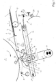
- FIG. 1 shows a belt table 1 with conveyor belts 3 rotating in the sheet transport direction 2.
- a feed table 4 with front marks 5 is assigned to the belt table 1.
- a sheet 6 to be aligned and a subsequent sheet 7 are shown on the belt table 1 / feed table 4.
- the feed table 4 is followed by a pre-gripper 8 and a cylinder 9, which has a sheet holding system 33.
- the pre-gripper 8 consists of rocking levers 11 pivotably mounted in frame points 10 and a gripper system 12.
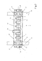
- the gripper system 12 has gripper fingers 14 clamped on a gripper shaft 13, which correspond to a gripper bar 15.
- the gripper shaft 13 is rotatably received in two bearing bodies 16 and can be rotated by means of a roller lever 23 which engages on the gripper shaft 13 and which corresponds to a link (not shown).
- the bearing body 16 are connected to one another by a box section 22.
- the gripper bar 15 is connected to the box section 22 and the bearing bodies 16.
- the bearing bodies 16 are mounted on guide rails 19 so as to be displaceable with the aid of two upper guide rollers 17 and a lower guide roller 18.
- An engagement member 20 is provided on the bearing bodies 16, which engages in a guide groove 21 provided in the rocker arms 11 and extending in the radial direction.
- the guide rails 19 are pivotally received in a bearing point 24, while an actuating device 25 engages at the opposite end facing the feed table 4.
- the actuating device 25 is designed as a cam mechanism, the roller lever 26 of which is held in engagement with a cam body 29 by means of a compression spring 27 via a cam roller 28.
- the roller lever 26 is mounted in a frame point 32 and is designed as a ternary link which, at its free end, engages with a driven member 30 in a groove 31 arranged in the guide rails 19.
- the guide rails 19 are mounted in the area of the cylinder 9 in the bearing point 24 and in the area of the feed table 4 the actuating device 25 acting on the guide rails 19 is provided. It is also possible to provide the actuating device 25 in the area of the cylinder 9 and the bearing point 24 in the area of the feed table 4.
- the sheet material to be processed is from a sheet feeder, not shown isolated and fed to the belt table 1 and from there onto the feed table 4 and with the front edge against the front marks located in a position on the feed table 4 5 transported. Accordingly, the sheet 6 to be aligned in Fig. 1 was after the Aligned leading edge. After aligning to the front edge, the one to be aligned Sheet 6 from the gripper system guided into a transfer position on the feed table 4 12 detected and after leading the front marks 5 in a position under the feed table 4 transported to the transfer position. The transport to be aligned is carried out Arc 6 on a straight path 34. In Fig. 1, the gripper system 12 is symbolic the way to the transfer position shown on the cylinder 9.
- the gripper system 12 is driven by a drive, not shown, which provides the rocker arms 11 with a periodic pivoting movement. Due to the active pairing of the engagement member 20 / guide groove 21, the bearing bodies 16 are displaced on the guide rails 19, and thus a movement of the gripper system 12 along the straight path 34 is realized.
- the transfer position is reached, in FIG. 1 the pre-gripper 8 is shown in this position, the sheet 6 to be aligned is transferred from the gripper system 12 to the sheet holding system 33 and the gripper system 12 is controlled beyond this position into a reversing position in which the direction of movement of the Rocker arm 11 is reversed. This position is symbolically represented in FIG. 1 by the gripper system 12.
- the guide rails 19 are given clockwise by the adjusting device 25 around the bearing point 24, so that the gripper system 12 follows a path 35 back to the feed table 4, which is at a distance below the rectilinear path 34 is provided. In Figure 1, this is symbolically represented by a dashed gripper system 12. Before the feed table 4 is reached, the guide rails 19 are pivoted back by the actuating device 25. The gripper system 12 is thus ready to take over the following sheet 7.
- the actuating device 25 is designed as a cam mechanism, to impose a law of motion on the cam body 29, so that the translational movement of the gripper system 12 during the movement back to the feed table 4 and the swiveling movement initiated by the cam body 29 overlap and thus that Gripper system 12 follows an arbitrarily designed path below the straight path 34.
- a feed table 4 with front marks 5 was provided for alignment with the front edge. It is also possible, instead of providing the front marks 5 on the feed table 4, assigning them to the gripper system 12 and aligning the sheets in the gripper system according to the front edge and, if appropriate, to the side edge, by displacing the gripper system 12 transversely to the sheet transport direction.
Landscapes
- Feeding Of Articles By Means Other Than Belts Or Rollers (AREA)
- Discharge By Other Means (AREA)
Abstract
Description
- Fig. 1
- eine schematische Darstellung eines Vorgreifers in Seitenansicht,
- Fig. 2
- eine Draufsicht auf einen Vorgreifer.
Die Führungsschienen 19 sind in einem Lagerpunkt 24 schwenkbar aufgenommen, während am gegenüberliegenden, dem Anlegtisch 4 zugewandten Ende eine Stelleinrichtung 25 angreift. Im Ausführungsbeispiel ist die Stelleinrichtung 25 als Kurvengetriebe ausgebildet, dessen Rollenhebel 26 mittels einer Druckfeder 27 über eine Kurvenrolle 28 in Eingriff mit einem Kurvenkörper 29 gehalten wird. Der Rollenhebel 26 ist in einem Gestellpunkt 32 gelagert und als ternäres Glied ausgebildet, der an seinem freien Ende mit einem Abtriebsglied 30 in eine in den Führungsschienen 19 angeordnete Nut 31 eingreift.
Im Ausführungsbeispiel sind die Führungsschienen 19 im Bereich des Zylinders 9 im Lagerpunkt 24 gelagert und im Bereich des Anlegtischs 4 ist die an den Führungsschienen 19 angreifende Stelleinrichtung 25 vorgesehen. Es ist auch möglich, die Stelleinrichtung 25 im Bereich des Zylinders 9 und den Lagerpunkt 24 im Bereich des Anlegtischs 4 vorzusehen.
Bei Erreichen der Übergabeposition, in Fig. 1 ist in dieser Position der Vorgreifer 8 dargestellt, wird der auszurichtende Bogen 6 von dem Greifersystem 12 an das Bogenhaltesystem 33 übergeben und das Greifersystem 12 über diese Position hinaus in eine Umkehrposition gesteuert, in der die Bewegungsrichtung der Schwinghebel 11 umgesteuert wird. Symbolhaft ist diese Position in Fig. 1 durch das Greifersystem 12 dargestellt. Vor dem Zurückführen des Greifersystems 12 an den Anlegtisch 4 zur Übernahme des Folgebogens 7 werden die Führungsschienen 19 durch die Stelleinrichtung 25 in Uhrzeigersinn um den Lagerpunkt 24 geschenkt, so dass das Greifersystem 12 zurück zum Anlegtisch 4 einer Bahn 35 folgt, die in einem Abstand unterhalb der geradlinigen Bahn 34 vorgesehen ist. In Figur 1 ist das durch ein gestricheltes Greifersystem 12 symbolhaft dargestellt. Vor Erreichen des Anlegtischs 4 werden durch die Stelleinrichtung 25 die Führungsschienen 19 zurückgeschwenkt. Damit ist das Greifersystem 12 bereit zur Übernahme des Folgebogens 7.
Es ist auch möglich, wenn z.B. die Stelleinrichtung 25 als Kurvengetriebe ausgebildet ist, dem Kurvenkörper 29 ein Bewegungsgesetz aufzuprägen, so dass sich die translatorische Bewegung des Greifersystems 12 bei der Bewegung zurück zum Anlegtisch 4 und die durch den Kurvenkörper 29 initiierte Schwenkbewegung überlagern und damit das Greifersystem 12 einer beliebig gestalteten Bahn unterhalb der geradlinigen Bahn 34 folgt.
Im Ausführungsbeispiel wurde ein Anlegtisch 4 mit Vordermarken 5 zum Ausrichten nach der Vorderkante vorgesehen. Es ist auch möglich, statt die Vordermarken 5 am Anlegtisch 4 vorzusehen, diese dem Greifersystem 12 zuzuordnen und die Bogen im Greifersystem nach der Vorderkante und ggf. nach der Seitenkante auszurichten, indem das Greifersystem 12 quer zur Bogentransportrichtung verschoben wird.
- 1
- Bändertisch
- 2
- Bogentransportrichtung
- 3
- Transportband
- 4
- Anlegtisch
- 5
- Vordermarke
- 6
- auszurichtender Bogen
- 7
- Folgebogen
- 8
- Vorgreifer
- 9
- Zylinder
- 10
- Gestellpunkt
- 11
- Schwinghebel
- 12
- Greifersystem
- 13
- Greiferwelle
- 14
- Greiferfinger
- 15
- Greiferaufschlagleiste
- 16
- Lagerkörper
- 17
- obere Führungsrolle
- 18
- untere Führungsrolle
- 19
- Führungsschiene
- 20
- Eingriffsglied
- 21
- Führungsnut
- 22
- Kastenprofil
- 23
- Rollenhebel
- 24
- Lagerpunkt
- 25
- Stelleinrichtung
- 26
- Rollenhebel
- 27
- Druckfeder
- 28
- Kurvenrolle
- 29
- Kurvenkörper
- 30
- Abtriebsglied
- 31
- Nut
- 32
- Gestellpunkt
- 33
- Bogenhaltesystem
- 34
- geradlinige Bahn
- 35
- Bahn
Claims (7)
- Antrieb eines Vorgreifers mit einem Greifersystem zum Transport von Bogen von einem Anlegtisch zu einem Bogenhaltesystem eines Zylinders, wobei das Greifersystem bei seiner Bewegung eine geradlinige Bahn beschreibt, dadurch gekennzeichnet, dass das Greifersystem (12) auf seinem Weg zurück zum Anlegtisch (4) einer Bahn (35) folgt, die in einem Abstand unterhalb der geradlinigen Bahn (34) vorgesehen ist.
- Antrieb nach Anspruch 1, dadurch gekennzeichnet, dass die Bahn (35) als Gerade ausgebildet ist.
- Antrieb nach Anspruch 1, dadurch gekennzeichnet, dass die Bahn (35) einen beliebigen Verlauf hat.
- Antrieb nach Anspruch 1, dadurch gekennzeichnet, dass das Greifersystem (12) auf Führungsschienen (19) verschiebbar gelagert ist, die sich mindestens vom Anlegtisch (4) bis in den Bereich des Zylinders (9) erstrecken.
- Antrieb nach Anspruch 1 und 4, dadurch gekennzeichnet, dass die Führungsschienen (19) in einem Lagerpunkt (24) gelagert sind und beabstandet dazu eine an den Führungsschienen (19) angreifende Stelleinrichtung (25) zum Schwenken der Führungsschienen (19) um den Lagerpunkt (24) vorgesehen ist.
- Antrieb nach Anspruch 1 und 4, dadurch gekennzeichnet, dass das Verschieben mittels periodisch angetriebener Schwinghebel (11) erfolgt.
- Antrieb nach Anspruch 1, 4 und 6, dadurch gekennzeichnet, dass ein mit dem Greifersystem (12) verbundenes Eingriffsglied (20) in eine radial im Schwinghebel (11) angeordnete Führungsnut (21) eingreift.
Applications Claiming Priority (2)
| Application Number | Priority Date | Filing Date | Title |
|---|---|---|---|
| DE10218172 | 2002-04-24 | ||
| DE2002118172 DE10218172A1 (de) | 2002-04-24 | 2002-04-24 | Antrieb eines Vorgreifers |
Publications (3)
| Publication Number | Publication Date |
|---|---|
| EP1356932A2 true EP1356932A2 (de) | 2003-10-29 |
| EP1356932A3 EP1356932A3 (de) | 2004-07-14 |
| EP1356932B1 EP1356932B1 (de) | 2006-02-22 |
Family
ID=28685262
Family Applications (1)
| Application Number | Title | Priority Date | Filing Date |
|---|---|---|---|
| EP20030006276 Expired - Lifetime EP1356932B1 (de) | 2002-04-24 | 2003-03-21 | Antrieb eines Vorgreifers |
Country Status (2)
| Country | Link |
|---|---|
| EP (1) | EP1356932B1 (de) |
| DE (2) | DE10218172A1 (de) |
Families Citing this family (2)
| Publication number | Priority date | Publication date | Assignee | Title |
|---|---|---|---|---|
| DE102007005016A1 (de) | 2006-02-27 | 2007-08-30 | Heidelberger Druckmaschinen Ag | Vorrichtung zum Transport von Bogen mittels einer Greifereinrichtung |
| CN118107262A (zh) * | 2024-03-21 | 2024-05-31 | 瑞安市博盛丝网印刷机械厂 | 一种全自动网板印刷机 |
Citations (1)
| Publication number | Priority date | Publication date | Assignee | Title |
|---|---|---|---|---|
| DE10013006A1 (de) | 2000-03-16 | 2001-09-27 | Roland Man Druckmasch | Vorrichtung für den Antrieb eines Vorgreifers |
Family Cites Families (8)
| Publication number | Priority date | Publication date | Assignee | Title |
|---|---|---|---|---|
| DE1126411B (de) * | 1961-01-28 | 1962-03-29 | Maschf Augsburg Nuernberg Ag | Bogenanlegevorrichtung |
| FR1312813A (fr) * | 1962-01-26 | 1962-12-21 | Maschf Augsburg Nuernberg Ag | Margeur |
| DE2156577B2 (de) * | 1971-11-15 | 1974-07-04 | Roland Offsetmaschinenfabrik Faber & Schleicher Ag, 6050 Offenbach | Vorgreiferschwinganlage |
| DD142694A1 (de) * | 1979-04-02 | 1980-07-09 | Guenter Weisbach | Bogenrotationsdruckmaschine mit einem von unten arbeitenden vorgreifer |
| DD142869A1 (de) * | 1979-04-02 | 1980-07-16 | Guenter Weisbach | Schwingender,von unten arbeitender vorgreifer |
| DE19543381C2 (de) * | 1995-11-21 | 1999-06-10 | Heidelberger Druckmasch Ag | Greifersteuerung für einen zyklisch schwingend angetriebenen Vorgreifer zum Einzelbogentransport in einer Bogendruckmaschine |
| DE19831976B4 (de) * | 1998-07-16 | 2010-07-29 | Heidelberger Druckmaschinen Ag | Vorrichtung zum Zuführen von Bogen zu einer Bogen verarbeitenden Maschine |
| DE10013611B4 (de) * | 2000-03-18 | 2006-07-06 | Koenig & Bauer Ag | Vorgreiferantrieb |
-
2002
- 2002-04-24 DE DE2002118172 patent/DE10218172A1/de not_active Withdrawn
-
2003
- 2003-03-21 EP EP20030006276 patent/EP1356932B1/de not_active Expired - Lifetime
- 2003-03-21 DE DE50302448T patent/DE50302448D1/de not_active Expired - Lifetime
Patent Citations (1)
| Publication number | Priority date | Publication date | Assignee | Title |
|---|---|---|---|---|
| DE10013006A1 (de) | 2000-03-16 | 2001-09-27 | Roland Man Druckmasch | Vorrichtung für den Antrieb eines Vorgreifers |
Also Published As
| Publication number | Publication date |
|---|---|
| EP1356932A3 (de) | 2004-07-14 |
| DE50302448D1 (de) | 2006-04-27 |
| DE10218172A1 (de) | 2003-11-13 |
| EP1356932B1 (de) | 2006-02-22 |
Similar Documents
| Publication | Publication Date | Title |
|---|---|---|
| EP0769376B1 (de) | Bogendruckmaschine | |
| DE102017111309A1 (de) | Bogenübernahme in Anlegeeinheit | |
| EP3248918B1 (de) | Bogenübernahme in anlegeeinheit | |
| DD142694A1 (de) | Bogenrotationsdruckmaschine mit einem von unten arbeitenden vorgreifer | |
| DE19600793C2 (de) | Vorrichtung zum Ausrichten von Bogen auf dem Anlegetisch einer Bogendruckmaschine | |
| EP0372237B1 (de) | Vorrichtung zur Passerkorrektur der Bogenaufdrucke in einer Bogenrotationsdruckmaschine | |
| DE19901699A1 (de) | Verfahren und eine Vorrichtung zur Durchführung des Verfahrens zur Beseitigung von rhythmischen Passerfehlern in Rotationsdruckmaschinen | |
| EP1356932B1 (de) | Antrieb eines Vorgreifers | |
| DE4012497C2 (de) | ||
| EP1356931B1 (de) | Vorgreifer mit einem Greifersystem | |
| EP1136262B1 (de) | Vorrichtung für den Antrieb eines Vorgreifers | |
| DD143152A1 (de) | Greifersteuerung an zylindern von bogenverarbeitenden maschinen,insbesondere druckmaschinen | |
| EP1310443A2 (de) | Bogenanleger | |
| DE10216758A1 (de) | Verfahren zum Ausrichten von Bogen nach der Seitenkante | |
| EP1357070B1 (de) | Einrichtung zum Ausrichten von Bogen | |
| CH615882A5 (de) | ||
| DE102009001190B4 (de) | Bogenverarbeitende Maschine mit einem Anlegetisch | |
| DE10233786A1 (de) | Flächige Bedruckstoffe verarbeitende Maschine mit einem Hilfsstapelträger | |
| DE10143098B4 (de) | Verfahren und Vorrichtung zum Führen und Übergeben eines Bogens in einer Druckmaschine | |
| DE19617542A1 (de) | Bogenwendegreifersystem in Wendetrommeln von Druckmaschinen | |
| DE102005029972A1 (de) | Anlegmarken | |
| DE102004060719A1 (de) | Bogendruckmaschine | |
| DE10355459A1 (de) | Anlegtisch | |
| DE10355515A1 (de) | Rotierender Vorgreifer | |
| EP1935817A2 (de) | Leitvorrichtung zur Bogenzufuhr an einer Druckmaschine |
Legal Events
| Date | Code | Title | Description |
|---|---|---|---|
| PUAI | Public reference made under article 153(3) epc to a published international application that has entered the european phase |
Free format text: ORIGINAL CODE: 0009012 |
|
| AK | Designated contracting states |
Kind code of ref document: A2 Designated state(s): AT BE BG CH CY CZ DE DK EE ES FI FR GB GR HU IE IT LI LU MC NL PT RO SE SI SK TR |
|
| AX | Request for extension of the european patent |
Extension state: AL LT LV MK |
|
| PUAL | Search report despatched |
Free format text: ORIGINAL CODE: 0009013 |
|
| AK | Designated contracting states |
Kind code of ref document: A3 Designated state(s): AT BE BG CH CY CZ DE DK EE ES FI FR GB GR HU IE IT LI LU MC NL PT RO SE SI SK TR |
|
| AX | Request for extension of the european patent |
Extension state: AL LT LV MK |
|
| 17P | Request for examination filed |
Effective date: 20040607 |
|
| 17Q | First examination report despatched |
Effective date: 20041029 |
|
| AKX | Designation fees paid |
Designated state(s): DE FR GB |
|
| GRAP | Despatch of communication of intention to grant a patent |
Free format text: ORIGINAL CODE: EPIDOSNIGR1 |
|
| GRAS | Grant fee paid |
Free format text: ORIGINAL CODE: EPIDOSNIGR3 |
|
| GRAA | (expected) grant |
Free format text: ORIGINAL CODE: 0009210 |
|
| AK | Designated contracting states |
Kind code of ref document: B1 Designated state(s): DE FR GB |
|
| REG | Reference to a national code |
Ref country code: GB Ref legal event code: FG4D Free format text: NOT ENGLISH |
|
| REF | Corresponds to: |
Ref document number: 50302448 Country of ref document: DE Date of ref document: 20060427 Kind code of ref document: P |
|
| GBT | Gb: translation of ep patent filed (gb section 77(6)(a)/1977) |
Effective date: 20060526 |
|
| ET | Fr: translation filed | ||
| PLBE | No opposition filed within time limit |
Free format text: ORIGINAL CODE: 0009261 |
|
| STAA | Information on the status of an ep patent application or granted ep patent |
Free format text: STATUS: NO OPPOSITION FILED WITHIN TIME LIMIT |
|
| 26N | No opposition filed |
Effective date: 20061123 |
|
| PGFP | Annual fee paid to national office [announced via postgrant information from national office to epo] |
Ref country code: FR Payment date: 20130408 Year of fee payment: 11 Ref country code: GB Payment date: 20130321 Year of fee payment: 11 |
|
| PGFP | Annual fee paid to national office [announced via postgrant information from national office to epo] |
Ref country code: DE Payment date: 20130330 Year of fee payment: 11 |
|
| REG | Reference to a national code |
Ref country code: DE Ref legal event code: R119 Ref document number: 50302448 Country of ref document: DE |
|
| GBPC | Gb: european patent ceased through non-payment of renewal fee |
Effective date: 20140321 |
|
| REG | Reference to a national code |
Ref country code: FR Ref legal event code: ST Effective date: 20141128 |
|
| REG | Reference to a national code |
Ref country code: DE Ref legal event code: R119 Ref document number: 50302448 Country of ref document: DE Effective date: 20141001 |
|
| PG25 | Lapsed in a contracting state [announced via postgrant information from national office to epo] |
Ref country code: FR Free format text: LAPSE BECAUSE OF NON-PAYMENT OF DUE FEES Effective date: 20140331 Ref country code: GB Free format text: LAPSE BECAUSE OF NON-PAYMENT OF DUE FEES Effective date: 20140321 Ref country code: DE Free format text: LAPSE BECAUSE OF NON-PAYMENT OF DUE FEES Effective date: 20141001 |