EP1352604A1 - Mophalter - Google Patents
Mophalter Download PDFInfo
- Publication number
- EP1352604A1 EP1352604A1 EP03405243A EP03405243A EP1352604A1 EP 1352604 A1 EP1352604 A1 EP 1352604A1 EP 03405243 A EP03405243 A EP 03405243A EP 03405243 A EP03405243 A EP 03405243A EP 1352604 A1 EP1352604 A1 EP 1352604A1
- Authority
- EP
- European Patent Office
- Prior art keywords
- base plate
- wings
- bolt
- holder according
- holder
- Prior art date
- Legal status (The legal status is an assumption and is not a legal conclusion. Google has not performed a legal analysis and makes no representation as to the accuracy of the status listed.)
- Withdrawn
Links
Images


Classifications
-
- A—HUMAN NECESSITIES
- A47—FURNITURE; DOMESTIC ARTICLES OR APPLIANCES; COFFEE MILLS; SPICE MILLS; SUCTION CLEANERS IN GENERAL
- A47L—DOMESTIC WASHING OR CLEANING; SUCTION CLEANERS IN GENERAL
- A47L13/00—Implements for cleaning floors, carpets, furniture, walls, or wall coverings
- A47L13/10—Scrubbing; Scouring; Cleaning; Polishing
- A47L13/20—Mops
- A47L13/24—Frames for mops; Mop heads
- A47L13/254—Plate frames
- A47L13/258—Plate frames of adjustable or foldable type
Definitions
- the invention relates to a holder according to the preamble of patent claim 1.
- Holders with two swiveling wings allow the free ones to be looped in Wing ends in two opposite pockets, which on one Mop cover can be formed.
- the distance between the wing ends is increased, whereby the mop cover is stretched on the holder.
- the free ends of the wings can only be retracted if the two collapsible wings can be pivoted against each other and so the Distance between their free ends is reduced.
- US 5,926,896 discloses a holder for releasably attaching a pug.
- the Holder has two plates, which are pivotably arranged on a support, on the support outer ends of the mop can be attached.
- the swiveling plates are by means of a locking device arranged on the support in a coplanar position ascertainable.
- the locking device has an elongated, rounded bolt, which is slidably guided in a guide sleeve.
- the guide pin is biased by a spring and strikes in the working position of the holder a stop at which on a first of the two pivotable plates is provided.
- the bolt can be released using an actuator so that the plates can be swiveled.
- the bolt moves in Direction of spring force from a retracted stop position in Spring force direction in a partially relaxed release position. As soon as one wing is partially pivoted, the bolt can move into the release position, in which is also the second wing released.
- the actuator consists of a pedal that can be pivoted by means of a hinge is attached to the first plate.
- a leaf spring provided on the pedal serves to to create a preload between the first plate and the support. At the Depressing the pedal can deflect the bolt upwards, and that Leaf spring forces the first plate to pivot clockwise and thus a release of the first wing.
- this is carried out by a holder according to the characteristics of the Claim 1 realized.
- the Actuator Through direct interaction of the Actuator with the bolt can move when actuated of the bolt against the force of the first spring means in a release position so that the wings of the holder are pivoted into the folded position can.
- the bolt is made by Actuator directly and against the spring force in the release position postponed.
- the holder By providing a base plate, the holder can essentially be formed symmetrically, which advantages when inserting the wing ends in the Brings pockets of a mop cover with it.
- the holder according to the invention also has the advantage that it is inexpensive to manufacture.
- the actuating member and the latch advantageously point to one another interacting backdrop areas.
- the backdrop surfaces have the advantage that the displacement directions of the actuator and the latch can be different.
- Appropriately are on the base plate at least two spaced guides for guiding the Riegel trained. These ensure that the bolt is properly guided.
- the bolt is flat and guided on opposite sides of the base plate.
- the guides on the opposite sides of the base plate can be continuous or interrupted. If on opposite sides the base plate at least two spaced guides are provided, this has the advantage that the bolt with appropriate Execution can be inserted from below into the guideway.
- the bolt is in the preferably hollow base plate or added to the bottom of the Base plate arranged.
- the base plate can be open from below, respectively. have a cavity for receiving the bolt.
- the wings can have latching means, which correspond with corresponding Interactively engage recesses on the bolt.
- the locking means pegs which in the clamping position corresponding projections or recesses on the holder form-fitting can work together.
- Per wing are preferably transverse to the longitudinal extent the holder is provided with two latching means spaced apart from one another. This has the advantage that the wing and base plate are practical in the clamping position are fixed to each other without play.
- the base plate advantageously has a frame part and one relative to the base plate sliding latch.
- This embodiment has the advantage that Moving the latch both wings can be released at the same time.
- the movable latch is between a release position and a locking position displaceable.
- First spring means are advantageously present, which lock the bolt preload the locking position. In the locking position of the bolt and The clamping position of the wings are firmly connected to the base plate.
- a release device is advantageous.
- the actuating member is advantageously an actuating pin, which is movable vertically or at an angle to the direction of displacement of the bolt.
- the bolt itself is preferably movable in the longitudinal direction of the tenter.
- the actuating pin and bolt advantageously act like a pillow over sliding surfaces together.
- the two wings are an advantage essentially the same, preferably identical. This has the advantage that the holder is in the folded position with respect to a vertical central plane is symmetrical. By an identical formation of the wings, the Production costs can be kept low. For plastic wings so that molding costs are saved.
- the wings can be on a common axis or preferably about two spaced axes be pivotable. These are advantageously directed parallel to one another.
- Means are advantageously provided to ensure that in the folded position Distance between the wings at their articulation point on the base plate is smaller than at their free ends. These funds can be obtained through at least one Swinging movement between base plate and sash limiting stop be educated. But it can, for example, also act between the wings Spring may be provided, which limits the pivoting movement. At this Embodiment, if necessary, the free ends of the wings against the compress the acting spring force even closer. Seat belts can also be used be present between the base plate and the wings, which the wings in the Hold the folding position at a certain angle.
- the ones described above Embodiments have the advantage that the articulated on the base plate Wings are oriented at an acute angle to each other in the folded position.
- a rolling means is advantageously present at the free end of a wing.
- the frictional resistance of the wing tips on the ground can be greatly reduced become.
- the base plate and / or the articulation points of the wings are preferably such formed that the unlocked wings to each other when the holder is raised Assume the fold-open position downwards in a V-shape.
- the wing is advantageously designed as a stop which is connected to the base plate can interact and the opening angle between the base plate and sash limited to an angle of ⁇ 90 °, preferably ⁇ 85 ° in the folded position.
- This allows a mop cover to tie with a strap to the holder.
- the straps are there expediently from two pieces of belt, one end of the piece of belt opposite sides of the mop cover are sewn on.
- the others Belt piece ends can through the loop devices on the wing looped and releasably connectable. With belts running through the mop cover remains after the free wing ends have run out with the belts hanging on the wings. Because of the equally long wings, the mop cover is open holder folded in the middle and can be wrung into a ring be given without having to be removed from the holder.
- the Infeed device is advantageous through at least one slot, preferably two spaced apart slots are formed, which are spaced apart the distal ends of the wings are present.
- the wings are advantageous in the tensioned position in the direction of the folded position biased.
- the jump through the provided spring means Sash automatically out of the cocking position as soon as the latch in the release position brought.
- the second spring means can be on the latch or on the wings be arranged or formed.
- This holder has the advantage that the wings jump out of the cocking position as soon as the Lanyards are released. Further advantageous embodiments are in the Subclaims defined.
- a holder according to the preamble of claim 26 is thereby characterizes that at the free (distal) ends of the wing rollers or lubricants are provided.
- This holder has the advantage that the wings automatically move into the Spread the clamping position when they are at an angle to the vertical Wings are placed on the floor. Further advantageous embodiments are defined in the subclaims.
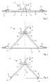
- the holder shown in Figures 1 and 2 consists essentially of three articulated interacting parts, namely a base plate 15 and two on the Base plate 15 hinged wings 19 and 20.
- the wings 19, 20 are two in Distance pivot axes 21,23 from an extended clamping position in a downward V-shaped foldable position.
- On the base plate 15 is a device 18 for articulating a stem, preferably in Shape of a universal joint, provided.
- the universal joint is with one Connection pin 17 equipped, on which a handle can be attached.
- a locking mechanism is used to keep the wings 19, 20 shown in FIG. 1 To connect the clamping position with the base plate 15 so that the wings 19, 20 in the stretched clamping position determined and not pivotable about the axes 21,23 are.
- the locking mechanism preferably consists of a movable bolt, which can be released with a release device 24 arranged on the base plate 15 is.
- FIGS Latch 43 arranged on the underside of the base plate.
- the base plate 15 can partially hollow for this purpose. be designed as a shell open at the bottom.
- latching means 41 (FIGS. 6 and 7) at a distance from the Swivel axes 21,23 formed.
- the locking means 41 are by at least one, preferably two pins 41 arranged at a distance from one another.
- the Bolt 43 is preferably flat and received flush in the base plate. He can have roughly the same dimensions as the base plate.
- the recesses 45 can one Have paragraph or an undercut 48, on which a pin 41 engage can.
- Two pegs 41 are at a distance from the longitudinal central axis on the wings arranged.
- the bolt 43 can have the shape of a double T (FIG. 12), wherein the recesses 45 are provided in the terminal head parts of the bolt 43 are.
- the bolt 43 can be moved relative to and parallel to the base plate 15.
- Spring means 47 which act between the base plate 15 and the bolt 43 hold the bolt 43 in the locked position.
- the release device respectively. includes the actuator 24 an actuating pin 55 which is movable perpendicular to the base plate 15.
- the Actuating pin 55 is arranged in an opening 76 in base plate 15.
- a feather 56 holds the actuating pin 55 in the starting position (FIG. 8).
- the spring 56 acts between the actuator head 54 and the base plate 15.
- the actuator pin 55 can - as will be explained in more detail below - in this way with the bolt 43 cooperate that the bolt 43 by advancing the actuating pin 55 in the Release position is displaceable. In the release position of the bolt 43, the pins arrive 41 from the engagement of the recesses 45, so that the wings 19, 20 from the Clamping position are pivotable.
- Figures 6 and 7 show a wing 19, 20 in more detail.
- the round holes 40 are in projections 39 intended.
- the projections 39 are in a preferred embodiment as Stops 26 formed, which in cooperation with the base plate 15 Limit the spreading angle of the wings 19.20.
- the spreading or Opening angle between base plate 15 and sash 19.20 maximum about 85 ° (s. Fig. 5).
- rollers 31 are provided at the opposite free (distal) end 27, 29 of the wings 19, 20 at the opposite free (distal) end 27, 29 of the wings 19, 20 there are two free rotatable rollers 31 are provided.
- the rollers 31 have the purpose of sliding the Ends 27, 29 via the mop cover 13 when the wings 19, 20 are inserted into the to facilitate opposing pockets 51, 52 of a mop cover.
- a recess 35 in the wings 19, 20 is arranged.
- a belt reel 37 is arranged between belt reel 37 and The edges of the recess 35 are slots 38, 38 'through which one Straps 33 of a mop cover can be looped.
- the straps 33 will preferably looped through the slots 38, 38 'such that the straps 33 are underneath the rolling means 31 extends.
- the rollers 31 and the belt roller 33 are each on one Axle bolt mounted, which from the bottom into a on the wing 19.20 trained axle bearing can be snapped.
- each pin 41 is symmetrical, so that it from both sides can work here equally with the bolt 43. Thanks to the symmetrical design of the peg can be the same wing 19.20 on each side of the holding part 15 are used.
- a link surface 49 is formed in the bolt 43, which can cooperate with the lower end of the actuating pin 55.
- the Actuating pin 55 has a head 54 at the upper end and one at the other end Sliding surface 57.
- the sliding surface 57 interacts with the link surface 49 in such a way that that when pushing the actuating pin 55 of the bolt 43 against the Spring force of the spring means 47 is moved into the release position.
- the Undercuts 46 come out of the engagement of the Recesses 45 so that the wings 19, 20 can be pivoted.
- the actuating pin 55 can be biased with a spring 56, as shown in FIG. in principle the spring means 47 acting on the bolt 43 can be dimensioned such that this both the bolt 43 and the actuating pin 55 in the starting position able to push back, so that an additional spring 56 is dispensed with can.
- the spring means 59 are preferably as an elastic pin protruding from the surface of the bolt 43 or tongues 59 formed, which in the tensioned position of the holder Preload between the base plate 15 and the wings 19, 20. As soon as the bolt 43 reaches the release position, the wings 19, 20 by the acting Spring force partially pivoted.
- the spring means 59 are integral with the bolt 43 trained. Counter-forms to the spring means can also be provided in the wings 19, 20 59 be formed, which cause the spring means only at its extreme Press the end onto the top of the wings 19, 20.
- 1 to 3 and 5 to 12 are the Pivot axes 21, 23 at a distance from one another and also at a distance from the underside arranged the base plate.
- the latter feature allows the wings to be flat train. In the tensioned position, the wings thus extend in one common plane on both sides of the swivel axes.
- the style attachment device is midway between the two Swivel axes 21, 23 are provided. By trained as stops 26 proximal ends of the wings 19, 20 remain in place when the holder 11 is raised an angle to the base plate 15.
- the exemplary embodiment according to FIG. 4 differs from the others Embodiments in that the wings 19, 20 around a common Pivot axis 22 are pivotable. They thus form in the folded position isosceles triangle.
- the holder 11 according to the invention can be used particularly advantageously in Connection with a mop cover 13, which is a band or a on the top Has straps 33 for connection to the holder 11.
- the mop cover 13 will Use attached to the holder 11 by the preferably two-part straps 33 through the spaces 38, 38 'are looped and the ends of the two belt parts e.g. be connected by means of a Velcro fastener.
- the wings 19, 20 are removed from the Locking released by the user releasing the device 24 by means of the foot pushes down. As a result, the bolt 43 is moved and the release position emotional. In this position, the spring means 59 press the wings 19, 20 and Base plate 15 apart.
- the folds Mop cover 13 in the middle. Hanging on the wings 19, 20, the mop cover in Rinse water swung and then wrung out in a ring without that he would have to be held in his hands. After wringing out the mop cover 13 is put back on the floor. In doing so he interprets himself, and the distal ends of the wings 19, 20 can be placed on the mop cover back become.
- the base plate 15 shown in FIGS. 10 to 12 essentially corresponds the base plate according to Figures 8 and 9. However, there are further details and alternative embodiments are shown.
- the base plate 15 has one cavity 71 open at the bottom, in which the bolt 43 is inserted.
- the cavity 71 has Areas with different depths.
- the end regions 73, 75 are formed deeper than the central region 77.
- Device 18 for attaching a stem is articulated. In the central area 77 acts the underside of the base plate 15 with the stops 26 of the wing 19.20 together.
- One end region 75 of the cavity 71 has in the longitudinal direction of the stenter a larger dimension than the other end region 73.
- a guide opening 76 in which the actuating pin 55 is guided.
- the central area 77 are on the Opposite sides of the base plate 15, two webs 62 are arranged.
- the bridges 62 each have two round holes 64 in which the axle bolts 61, 63 for fastening the Wings are stored.
- the axle bolts 61, 63 are only on one side in the web 62 stored, on the other hand they are cantilevered in the round holes 40 Grip wing 19.20.
- the two axle bolts arranged in the same web 62 are in one piece with a connecting the two axle bolts 61,63 Connection part made of plastic.
- the wings are e.g. brought into the tensioned position, and the Axle bolts 61, 63 from the outside into the round holes 40 and 64 put into it.
- the bolt has an extending in the direction of movement Bolt 83, which through an opening 84 in the wall of the base plate 15th passes through and in a accommodated in the opening 84 or Guide part 85 is mounted (Fig. 12).
- the bearing part 85 has a diameter 87, which in its width corresponds to the cross section of the bolt 83.
- the bolt 83 is passed through the opening 84 is inserted in the base plate 15.
- the latch 43 is then in the Holding part 16 inserted. Areas are left on the bolt 43, which allow the Bolt 43 in an extreme position beyond the release position next to the tabs 81 in to insert the cavity 71.
- the spring 47 is through the opening 84 on the bolt 83rd attached.
- the bearing part 85 By inserting the bearing part 85 into the opening 84, the spring 47 biased.
- the bearing part 85 snaps into the opening 84 so that it is the Transfers spring force to the edge of the base plate 15.
- the actuating pin 55 Before inserting the bolt into the cavity 71, the actuating pin 55 must be in the square guide opening 76 may be inserted.
- the actuating pin has Projections 88, which abut the edge of the guide opening 76, so that this after cannot slide out of the guide opening at the top. From above is for security of the actuating pin 55, a head 54 is connected to the actuating pin.
- the Actuating pin 55 has a bevelled sliding surface 49, which with a rectified backdrop surface 49 cooperates on the bolt.
- the bolt according to FIG. 12 also has the paragraphs 48, the bolt 83 and the spring means 59 still slide ribs 89, which cooperate with the inside of the cavity 71. Because the inside of the Cavity 71 is stepped, the sliding ribs are also of different heights.
- the holder can also be designed as a frame construction.
- the holder is basically made of metal, is plastic, e.g. Polyamide, as Manufacturing material preferred.
- plastic e.g. Polyamide
- the plastic parts preferably manufactured by injection molding.
Landscapes
- Cleaning Implements For Floors, Carpets, Furniture, Walls, And The Like (AREA)
Abstract
Description
- Fig. 1
- ein erstes Ausführungsbeispiel eines erfindungsgemässen Halters in Spannstellung mit zwei an einer Grundplatte angeordneten, verschwenkbaren Flügeln und einem aufgespannten Wischbezug;
- Fig. 2
- den Halter mit Wischbezug nach Figur 1 mit verschwenkten Flügeln (Faltstellung);
- Fig. 3
- den Halter wie in Figur 2, jedoch mit Abrollmitteln an den Flügelenden;
- Fig. 4
- ein zweites Ausführungsbeispiel eines Halters mit einer gemeinsamen Achse für beide Flügel;
- Fig. 5
- den Halter nach Figur 3 mit Einschlaufmitteln für eine Wischbezuggurte und einem Wischbezug mit einer solchen Gurte;
- Fig. 6
- eine Draufsicht auf einen Flügel des Halters gemäss Figur 5;
- Fig. 7
- einen Längsschnitt durch den Flügel gemäss Figur 6;
- Fig. 8
- einen Längsschnitt durch eine Grundplatte;
- Fig. 9
- eine Untersicht der Grundplatte nach Figur 8;
- Fig. 10
- eine Untersicht einer bevorzugter Ausführungsform einer Grundplatte mit Riegel,
- Fig. 11
- eine Untersicht der Grundplatte gemäss Fig. 10, ohne Riegel,
- Fig. 12
- eine Aufsicht auf den Riegel gemäss Fig. 10.
- 11
- Halter
- 13
- Wischbezug
- 15
- Grundplatte
- 17
- Verbindungszapfen
- 18
- Vorrichtung zum Anbringen oder Ankoppeln eines Stiels
- 19,20
- Flügel
- 21,23
- Schwenkachsen der Flügel 19,20
- 22
- gemeinsame Schwenkachse beider Flügel 19,20
- 24
- Lösevorrichtung
- 26
- Anschlag der Vorsprünge 39
- 27/29
- distales Ende der Bügel 19,20
- 31
- Rolle/ Abrollmittel
- 33
- Gurte eines Wischbezugs
- 35
- Ausnehmung für Gurtrolle 37
- 37
- Gurtrolle
- 38,38'
- Schlitze zwischen Rändern der Ausnehmung 35 und der Rolle 37
- 39
- Vorsprünge der Flügel 19,20
- 40
- Rundlöcher für Aufnahme der Achsstifte 21
- 41
- Einrastmittel (Zapfen)
- 43
- Riegel
- 45
- Ausnehmungen resp. Aussparungen im Riegel 43 für die Einrastmittel 41
- 46
- Hinterschneidung des Zapfens 41
- 47
- erste Federmittel, welches Riegel 43 in die Arretierstellung vorspannt
- 48
- Absatz der Aussparung 45 am Riegel 43
- 49
- Kulissenfläche
- 51,52
- Taschen des Wischbezugs 13
- 54
- Kopf der Lösevorrichtung 24
- 55
- Betätigungsstift
- 56
- Feder des Betätigungsstifts 55
- 57
- Gleitfläche am Betätigungsstift 55
- 58
- Gleitfläche an den Zapfen 41
- 59
- zweite Federmittel, die die Flügel 19,20 in Richtung Faltstellung vorspannen
- 60
- Pfeil in Richtung Lösestellung des Riegels 43
- 61,63
- Achsbolzen zur Befestigung der Flügel 19,20
- 62
- Stege
- 64
- Rundlöcher in den Stegen 62
- 65
- Zwischenraum
- 66
- Mittelteil des Riegels 43
- 71
- Kavität der Grundplatte 15
- 73,75,77
- Bereiche der Kavität 71
- 76
- Führungsöffnung für Betätigungsstift 55
- 81
- Laschen
- 83
- Bolzen am Riegel 43
- 84
- grössere Öffnung zur Aufnahme des Lagerteils 85
- 85
- Lagerteil für Bolzen 83
- 87
- kleinere Öffnung im Lagerteil zur Aufnahme des Bolzens 83
- 89
- Gleitrippen am Riegel 43
Claims (28)
- Halter (11) mit einem länglichen Spannrahmen (15,19,20) für die Aufnahme eines Wischbezugs (13), mitdadurch gekennzeichnet, dass das Betätigungsorgan (55) direkt mit dem Riegel (43) zusammenwirkt derart, dass bei der Betätigung des Betätigungsorgans (55) eine Verschiebung des Riegels (43) entgegen der Kraft der ersten Federmittel (47) in eine Lösestellung bewirkt ist.einer Grundplatte (15)wenigstens zwei relativ zueinander verschwenkbaren Flügeln (19,20), welche an der Grundplatte (15) angelenkt und um eine Achse quer zur Längserstreckung des Spannrahmens (15,19,20) zwischen einer Spannstellung und einer Faltstellung verschwenkbar sind,einem relativ zur Grundplatte (15) in einer Verschieberichtung verschiebbaren Riegel (43) zur Feststellung der Flügel (19,20) an der Grundplatte (15) in der Spannstellung;zwischen der Grundplatte (15) und dem Riegel (43) wirkenden ersten Federmitteln (47) zum Vorspannen des Riegels (43) in eine Arretierstellung; undeiner an der Grundplatte (15) vorgesehenen Lösevorrichtung in Gestalt eines beweglichen Betätigungsorgans (55) zum Öffnen des Spannrahmens, sowie gegebenenfallseiner am Halter (11) vorgesehenen Vorrichtung (17) für die vorzugsweise gelenkige Anbringung eines Stiels am Spannrahmen (15,19,20),
- Halter nach Anspruch 1, dadurch gekennzeichnet, dass das Betätigungsorgan (55) und der Riegel (43) miteinander zusammenwirkende Kulissenflächen (56,57) aufweisen.
- Halter nach Anspruch 1 oder 2, dadurch gekennzeichnet, dass an der Grundplatte (15) mindestens zwei in Abstand voneinander angeordnete Führungen (81) zur Führung des Riegels (43) ausgebildet sind.
- Halter nach einem der Ansprüche 1 bis 3, dadurch gekennzeichnet, dass der Riegel (43) flach und an gegenüberliegenden Seiten an der Grundplatte (15) geführt ist.
- Halter nach einem der Ansprüche 1 bis 4, dadurch gekennzeichnet, dass der Riegel (43,41) und die Flügel (19,20) in der Arretierstellung formschlüssig zusammenwirken.
- Halter nach einem der Ansprüche1 bis 5, dadurch gekennzeichnet, dass die Flügel (19,20) Einrastmittel (41) aufweisen, welche mit entsprechenden Ausnehmungen (48) am Riegel (43) formschlüssig zusammenwirken können.
- Halter nach Anspruch 6, dadurch gekennzeichnet, dass an jedem Flügel (19,20) quer zur Längserstreckung des Halters zwei in Abstand voneinander angeordnete Einrastmittel (41) vorgesehen sind.
- Halter nach einem der Ansprüche 1 bis 7, dadurch gekennzeichnet, dass die Grundplatte (15) als nach unten offene Schale oder Rahmenteil (16)ausgebildet ist, in welchem der Riegel (43) zwischen einer Arretierstellung und einer Löseposition verschiebbar angeordnet ist.
- Halter nach einem der Ansprüche 1 bis 8, dadurch gekennzeichnet, dass zwischen der Grundplatte (15) und dem Riegel (43) wirkende erste Federmittel (47) vorgesehen sind, mit denen der Riegel (43) in die Arretierstellung vorgespannt ist.
- Halter nach Anspruch 9, dadurch gekennzeichnet, dass bei Betätigung des Betätigungsorgans (55) eine Verschiebung des Riegels (43) parallel zur Oberseite der Grundplatte (11) in Richtung der Längserstreckung des Spannrahmens (19,15,20), bewirkt ist.
- Halter nach Anspruch 10, dadurch gekennzeichnet, dass das Betätigungsorgan (55) im wesentlichen senkrecht zur Oberseite der Grundplatte (15) beweglich ist.
- Halter nach einem der Ansprüche 1 bis 13, dadurch gekennzeichnet, dass die Flügel (19,20) um zwei in Abstand voneinander angeordnete Schwenkachsen (21,23) an der Grundplatte (15) angelenkt sind.
- Halter nach einem der Ansprüche 1 bis 14, dadurch gekennzeichnet, dass zwischen der Grundplatte (15) und wenigstens einem Flügel (19,20) wirkende zweite Federmittel (59) vorgesehen sind, um die Flügel (19,20) in der Spannstellung in Richtung Faltstellung vorzuspannen.
- Halter nach Anspruch 13, dadurch gekennzeichnet, dass die zweiten Federmittel (59) am Riegel (43) angeordnet oder vorgesehen sind und zumindest in der Löseposition eine Kraft auf die Flügel (19,20) ausüben.
- Halter nach einem der Ansprüche 1 bis 14, dadurch gekennzeichnet, dass die beiden Flügel (19,20) im Wesentlichen gleich, vorzugsweise identisch, ausgebildet sind.
- Halter nach einem der Ansprüche 1 bis 15, dadurch gekennzeichnet, dass die Vorrichtung (18) für die Anbringung eines Stiels ein Kreuzgelenk mit Verbindungszapfen (17) ist.
- Halter nach einem der Ansprüche 1 bis 16, dadurch gekennzeichnet, dass die Vorrichtung (18) für die Anbringung eines Stiels oberhalb der gemeinsamen Schwenkachse (22) der beiden Flügel (19,20) oder im Falle von zwei in Abstand zueinander angeordneten Schwenkachsen (21,23) oberhalb und symmetrisch zu den Schwenkachsen (21,23) der beiden Flügel (19,20) angeordnet ist.
- Halter nach einem der Ansprüche 1 bis 17, dadurch gekennzeichnet, dass Mittel (26) vorgesehen sind, die gewährleisten, dass der Abstand zwischen den Flügeln (19,20) in der Faltstellung an deren Anlenkstelle (21,23) an der Grundplatte(15) kleiner ist als an deren freien Enden (27,29).
- Halter nach einem der Ansprüche 1 bis 17, dadurch gekennzeichnet, dass am proximalen Ende der Flügel (19,20) ein Anschlag (26) ausgebildet ist, welcher mit der Grundplatte (15) zusammenwirken kann und den Öffnungswinkel zwischen Grundplatte (15) und Flügel (19,20) in der Faltstellung auf einen Winkel < 90°, vorzugsweise < 85° begrenzt.
- Halter nach einem der Ansprüche 1 bis 19, dadurch gekennzeichnet, dass am freien (distalen) Ende (27,29) eines Flügels (19,20) Abrollmittel (31) vorhanden sind.
- Halter nach einem der Ansprüche 1 bis 13, weiter gekennzeichnet durch eine Einschlaufvorrichtung (35,37) an den Flügeln (19,20) zum Einschlaufen einer Gurte (33) eines Wischbezuges (13).
- Halter nach Anspruch 27, dadurch gekennzeichnet, dass die Einschlaufvorrichtung (35,37) durch mindestens einen Schlitz (38) gebildet ist, welcher in Abstand zu den proximalen Ende der Flügel (19,20) vorgesehen ist.
- Halter nach einem der Ansprüche 1 bis 24, dadurch gekennzeichnet, dass die Grundplatte (15) an gegenüberliegenden Seiten gegeneinander orientierte Führungslaschen (81) für den Riegel (43) aufweist.
- Halter (11) mit einem länglichen Spannrahmen (15,19,20) für die Aufnahme eines Wischbezugs (13), mit wenigstens zwei relativ zueinander verschwenkbaren Flügeln (19,20), welche an einer Grundplatte (15) angelenkt und um eine Achse quer zur Längserstreckung des Spannrahmens (15,19,20) zwischen einer Spannstellung und einer Faltstellung verschwenkbar und in der Spannstellung mittels Arretiermitteln feststellbar sind, und einer am Halter vorgesehenen Vorrichtung (17) für die vorzugsweise gelenkige Anbringung eines Stiels am Spannrahmen (15,19,20),
dadurch gekennzeichnet, dass an der Grundplatte (15) oder am Riegel (43) Federmittel (43,41) vorgesehen sind, welche in der Spannstellung eine in Richtung Faltstellung wirkende Vorspannung zwischen der Grundplatte (15) und den Flügeln (19,20) bewirken. - Halter nach Anspruch 24, weiter gekennzeichnet durch einen der Ansprüche 2 bis 23.
- Halter (11) mit einem länglichen Spannrahmen (15,19,20) für die Aufnahme eines Wischbezugs (13), mit wenigstens zwei relativ zueinander verschwenkbaren Flügeln (19,20), welche Flügel (19,20) zwischen einer Spannstellung und einer Faltstellung verschwenkbar und in der Spannstellung feststellbar sind, und einer am Halter vorgesehenen Vorrichtung (17) für die vorzugsweise gelenkige Anbringung eines Stiels am Spannrahmen (15,19,20),
dadurch gekennzeichnet, dass an den freien (distalen) Enden der Flügel (19,20) Rollen oder Gleitmittel vorgesehen sind. - Halter nach Anspruch 26, weiter gekennzeichnet durch ein an der Grundplatte (15) angeordnetes Betätigungsorgan, bei dessen Betätigung eine Verschiebung des Riegels (43) von der Arretierstellung in die Lösestellung bewirkbar ist.
- Halter nach Anspruch 26 oder 27, weiter gekennzeichnet durch einen der Ansprüche 2 bis 23.
Applications Claiming Priority (2)
| Application Number | Priority Date | Filing Date | Title |
|---|---|---|---|
| CH5952002 | 2002-04-09 | ||
| CH5952002 | 2002-04-09 |
Publications (1)
| Publication Number | Publication Date |
|---|---|
| EP1352604A1 true EP1352604A1 (de) | 2003-10-15 |
Family
ID=28048298
Family Applications (1)
| Application Number | Title | Priority Date | Filing Date |
|---|---|---|---|
| EP03405243A Withdrawn EP1352604A1 (de) | 2002-04-09 | 2003-04-09 | Mophalter |
Country Status (1)
| Country | Link |
|---|---|
| EP (1) | EP1352604A1 (de) |
Cited By (4)
| Publication number | Priority date | Publication date | Assignee | Title |
|---|---|---|---|---|
| WO2008028749A1 (de) * | 2006-09-05 | 2008-03-13 | BSH Bosch und Siemens Hausgeräte GmbH | Bodendüse für hartböden |
| ITPD20110259A1 (it) * | 2011-08-03 | 2013-02-04 | T T S S R L Tecno Trolley System | Cinematismo di blocco e di sblocco di una base per mop |
| EP3967205A2 (de) | 2020-09-15 | 2022-03-16 | Eyco Direkt Anstalt | Eimer mit einer auf den eimer aufsetzbaren auswringvorrichtung |
| EP3967203A2 (de) | 2020-09-15 | 2022-03-16 | Eyco Direkt Anstalt | Bodenwischgerät und bodenwischsystem |
Citations (4)
| Publication number | Priority date | Publication date | Assignee | Title |
|---|---|---|---|---|
| DE3808310A1 (de) * | 1988-03-12 | 1989-09-21 | Jost Mueller | Mophalter |
| DE29519320U1 (de) * | 1995-01-26 | 1996-01-25 | Cervellin Sergio | Wischgerät |
| US5926896A (en) * | 1997-11-25 | 1999-07-27 | Rubbermaid Commercial Products Llc | Collapsible cleaning implement |
| EP1147735A2 (de) * | 2000-04-17 | 2001-10-24 | Rafael Castaner, S.L. | Faltbares Reinigungsgerät |
-
2003
- 2003-04-09 EP EP03405243A patent/EP1352604A1/de not_active Withdrawn
Patent Citations (4)
| Publication number | Priority date | Publication date | Assignee | Title |
|---|---|---|---|---|
| DE3808310A1 (de) * | 1988-03-12 | 1989-09-21 | Jost Mueller | Mophalter |
| DE29519320U1 (de) * | 1995-01-26 | 1996-01-25 | Cervellin Sergio | Wischgerät |
| US5926896A (en) * | 1997-11-25 | 1999-07-27 | Rubbermaid Commercial Products Llc | Collapsible cleaning implement |
| EP1147735A2 (de) * | 2000-04-17 | 2001-10-24 | Rafael Castaner, S.L. | Faltbares Reinigungsgerät |
Cited By (7)
| Publication number | Priority date | Publication date | Assignee | Title |
|---|---|---|---|---|
| WO2008028749A1 (de) * | 2006-09-05 | 2008-03-13 | BSH Bosch und Siemens Hausgeräte GmbH | Bodendüse für hartböden |
| ITPD20110259A1 (it) * | 2011-08-03 | 2013-02-04 | T T S S R L Tecno Trolley System | Cinematismo di blocco e di sblocco di una base per mop |
| WO2013018022A1 (en) * | 2011-08-03 | 2013-02-07 | T.T.S. S.R.L. | Locking and unlocking kinetic motion of a mop base |
| CN103813743A (zh) * | 2011-08-03 | 2014-05-21 | Tts手推车装置有限公司 | 拖布基座的锁定和解锁运动学系统 |
| CN103813743B (zh) * | 2011-08-03 | 2016-08-17 | Tts手推车装置有限公司 | 拖布基座的锁定和解锁运动学系统 |
| EP3967205A2 (de) | 2020-09-15 | 2022-03-16 | Eyco Direkt Anstalt | Eimer mit einer auf den eimer aufsetzbaren auswringvorrichtung |
| EP3967203A2 (de) | 2020-09-15 | 2022-03-16 | Eyco Direkt Anstalt | Bodenwischgerät und bodenwischsystem |
Similar Documents
| Publication | Publication Date | Title |
|---|---|---|
| DE3720564C2 (de) | ||
| DE2942806A1 (de) | Vorrichtung zum festhalten eines skistiefelendes auf einem ski, insbesondere bindung fuer einen langlaufski | |
| DE3442780A1 (de) | Alpiner skischuh | |
| DE8618392U1 (de) | Gliederverschluß für Sportartikel, insbesondere für Sportschuhe | |
| DE7804494U1 (de) | Spannschnalle | |
| DE2707626A1 (de) | Langlaufbindung | |
| EP0123820A2 (de) | Vorrichtung zur Längsverstellung von Skibindungen | |
| DE19714861C1 (de) | Spannvorrichtung | |
| EP1352604A1 (de) | Mophalter | |
| DE3151585C2 (de) | ||
| DE4403550C1 (de) | Reinigungsgerät | |
| DE4239317C1 (de) | Tuchhalter | |
| EP1188406B1 (de) | Wischer | |
| DE2308896A1 (de) | Ausloesebindung mit sohlenplatte | |
| DE102010014054A1 (de) | Öffnungshilfe für Energieführungsketten | |
| CH653560A5 (de) | Mit einer skibremse kombinierter fersenhalter. | |
| DE1941025A1 (de) | Skistiefelverschluss | |
| DE202005019125U1 (de) | Künstliches Kniegelenk mit minimalem Kniewinkel | |
| DE19541700C2 (de) | Scharnier | |
| DE2613580A1 (de) | Griff fuer skistock | |
| DE4434065C1 (de) | Reinigungseinrichtung | |
| DE4022326C2 (de) | Vorrichtung für das Naß- oder Feuchtwischen von Fußböden | |
| DE2709955C3 (de) | Formschlüssige Verriegelung für Schließen, Verschlüsse o.dgl., beispielsweise für Schmuckwaren, Uhrarmbänder etc | |
| EP3967203B1 (de) | Bodenwischgerät und bodenwischsystem | |
| DE60200066T2 (de) | Faltverschluss für Armband |
Legal Events
| Date | Code | Title | Description |
|---|---|---|---|
| PUAI | Public reference made under article 153(3) epc to a published international application that has entered the european phase |
Free format text: ORIGINAL CODE: 0009012 |
|
| AK | Designated contracting states |
Kind code of ref document: A1 Designated state(s): AT BE BG CH CY CZ DE DK EE ES FI FR GB GR HU IE IT LI LU MC NL PT RO SE SI SK TR |
|
| AX | Request for extension of the european patent |
Extension state: AL LT LV MK |
|
| 17P | Request for examination filed |
Effective date: 20030830 |
|
| AKX | Designation fees paid |
Designated state(s): AT BE BG CH CY CZ DE DK EE ES FI FR GB GR HU IE IT LI LU MC NL PT RO SE SI SK TR |
|
| 17Q | First examination report despatched |
Effective date: 20050330 |
|
| GRAP | Despatch of communication of intention to grant a patent |
Free format text: ORIGINAL CODE: EPIDOSNIGR1 |
|
| RAP1 | Party data changed (applicant data changed or rights of an application transferred) |
Owner name: HANS RAAB UMWELTSTIFTUNG |
|
| STAA | Information on the status of an ep patent application or granted ep patent |
Free format text: STATUS: THE APPLICATION IS DEEMED TO BE WITHDRAWN |
|
| 18D | Application deemed to be withdrawn |
Effective date: 20070426 |