EP1352604A1 - Mop frame - Google Patents
Mop frame Download PDFInfo
- Publication number
- EP1352604A1 EP1352604A1 EP03405243A EP03405243A EP1352604A1 EP 1352604 A1 EP1352604 A1 EP 1352604A1 EP 03405243 A EP03405243 A EP 03405243A EP 03405243 A EP03405243 A EP 03405243A EP 1352604 A1 EP1352604 A1 EP 1352604A1
- Authority
- EP
- European Patent Office
- Prior art keywords
- base plate
- wings
- bolt
- holder according
- holder
- Prior art date
- Legal status (The legal status is an assumption and is not a legal conclusion. Google has not performed a legal analysis and makes no representation as to the accuracy of the status listed.)
- Withdrawn
Links
Images


Classifications
-
- A—HUMAN NECESSITIES
- A47—FURNITURE; DOMESTIC ARTICLES OR APPLIANCES; COFFEE MILLS; SPICE MILLS; SUCTION CLEANERS IN GENERAL
- A47L—DOMESTIC WASHING OR CLEANING; SUCTION CLEANERS IN GENERAL
- A47L13/00—Implements for cleaning floors, carpets, furniture, walls, or wall coverings
- A47L13/10—Scrubbing; Scouring; Cleaning; Polishing
- A47L13/20—Mops
- A47L13/24—Frames for mops; Mop heads
- A47L13/254—Plate frames
- A47L13/258—Plate frames of adjustable or foldable type
Definitions
- the invention relates to a holder according to the preamble of patent claim 1.
- Holders with two swiveling wings allow the free ones to be looped in Wing ends in two opposite pockets, which on one Mop cover can be formed.
- the distance between the wing ends is increased, whereby the mop cover is stretched on the holder.
- the free ends of the wings can only be retracted if the two collapsible wings can be pivoted against each other and so the Distance between their free ends is reduced.
- US 5,926,896 discloses a holder for releasably attaching a pug.
- the Holder has two plates, which are pivotably arranged on a support, on the support outer ends of the mop can be attached.
- the swiveling plates are by means of a locking device arranged on the support in a coplanar position ascertainable.
- the locking device has an elongated, rounded bolt, which is slidably guided in a guide sleeve.
- the guide pin is biased by a spring and strikes in the working position of the holder a stop at which on a first of the two pivotable plates is provided.
- the bolt can be released using an actuator so that the plates can be swiveled.
- the bolt moves in Direction of spring force from a retracted stop position in Spring force direction in a partially relaxed release position. As soon as one wing is partially pivoted, the bolt can move into the release position, in which is also the second wing released.
- the actuator consists of a pedal that can be pivoted by means of a hinge is attached to the first plate.
- a leaf spring provided on the pedal serves to to create a preload between the first plate and the support. At the Depressing the pedal can deflect the bolt upwards, and that Leaf spring forces the first plate to pivot clockwise and thus a release of the first wing.
- this is carried out by a holder according to the characteristics of the Claim 1 realized.
- the Actuator Through direct interaction of the Actuator with the bolt can move when actuated of the bolt against the force of the first spring means in a release position so that the wings of the holder are pivoted into the folded position can.
- the bolt is made by Actuator directly and against the spring force in the release position postponed.
- the holder By providing a base plate, the holder can essentially be formed symmetrically, which advantages when inserting the wing ends in the Brings pockets of a mop cover with it.
- the holder according to the invention also has the advantage that it is inexpensive to manufacture.
- the actuating member and the latch advantageously point to one another interacting backdrop areas.
- the backdrop surfaces have the advantage that the displacement directions of the actuator and the latch can be different.
- Appropriately are on the base plate at least two spaced guides for guiding the Riegel trained. These ensure that the bolt is properly guided.
- the bolt is flat and guided on opposite sides of the base plate.
- the guides on the opposite sides of the base plate can be continuous or interrupted. If on opposite sides the base plate at least two spaced guides are provided, this has the advantage that the bolt with appropriate Execution can be inserted from below into the guideway.
- the bolt is in the preferably hollow base plate or added to the bottom of the Base plate arranged.
- the base plate can be open from below, respectively. have a cavity for receiving the bolt.
- the wings can have latching means, which correspond with corresponding Interactively engage recesses on the bolt.
- the locking means pegs which in the clamping position corresponding projections or recesses on the holder form-fitting can work together.
- Per wing are preferably transverse to the longitudinal extent the holder is provided with two latching means spaced apart from one another. This has the advantage that the wing and base plate are practical in the clamping position are fixed to each other without play.
- the base plate advantageously has a frame part and one relative to the base plate sliding latch.
- This embodiment has the advantage that Moving the latch both wings can be released at the same time.
- the movable latch is between a release position and a locking position displaceable.
- First spring means are advantageously present, which lock the bolt preload the locking position. In the locking position of the bolt and The clamping position of the wings are firmly connected to the base plate.
- a release device is advantageous.
- the actuating member is advantageously an actuating pin, which is movable vertically or at an angle to the direction of displacement of the bolt.
- the bolt itself is preferably movable in the longitudinal direction of the tenter.
- the actuating pin and bolt advantageously act like a pillow over sliding surfaces together.
- the two wings are an advantage essentially the same, preferably identical. This has the advantage that the holder is in the folded position with respect to a vertical central plane is symmetrical. By an identical formation of the wings, the Production costs can be kept low. For plastic wings so that molding costs are saved.
- the wings can be on a common axis or preferably about two spaced axes be pivotable. These are advantageously directed parallel to one another.
- Means are advantageously provided to ensure that in the folded position Distance between the wings at their articulation point on the base plate is smaller than at their free ends. These funds can be obtained through at least one Swinging movement between base plate and sash limiting stop be educated. But it can, for example, also act between the wings Spring may be provided, which limits the pivoting movement. At this Embodiment, if necessary, the free ends of the wings against the compress the acting spring force even closer. Seat belts can also be used be present between the base plate and the wings, which the wings in the Hold the folding position at a certain angle.
- the ones described above Embodiments have the advantage that the articulated on the base plate Wings are oriented at an acute angle to each other in the folded position.
- a rolling means is advantageously present at the free end of a wing.
- the frictional resistance of the wing tips on the ground can be greatly reduced become.
- the base plate and / or the articulation points of the wings are preferably such formed that the unlocked wings to each other when the holder is raised Assume the fold-open position downwards in a V-shape.
- the wing is advantageously designed as a stop which is connected to the base plate can interact and the opening angle between the base plate and sash limited to an angle of ⁇ 90 °, preferably ⁇ 85 ° in the folded position.
- This allows a mop cover to tie with a strap to the holder.
- the straps are there expediently from two pieces of belt, one end of the piece of belt opposite sides of the mop cover are sewn on.
- the others Belt piece ends can through the loop devices on the wing looped and releasably connectable. With belts running through the mop cover remains after the free wing ends have run out with the belts hanging on the wings. Because of the equally long wings, the mop cover is open holder folded in the middle and can be wrung into a ring be given without having to be removed from the holder.
- the Infeed device is advantageous through at least one slot, preferably two spaced apart slots are formed, which are spaced apart the distal ends of the wings are present.
- the wings are advantageous in the tensioned position in the direction of the folded position biased.
- the jump through the provided spring means Sash automatically out of the cocking position as soon as the latch in the release position brought.
- the second spring means can be on the latch or on the wings be arranged or formed.
- This holder has the advantage that the wings jump out of the cocking position as soon as the Lanyards are released. Further advantageous embodiments are in the Subclaims defined.
- a holder according to the preamble of claim 26 is thereby characterizes that at the free (distal) ends of the wing rollers or lubricants are provided.
- This holder has the advantage that the wings automatically move into the Spread the clamping position when they are at an angle to the vertical Wings are placed on the floor. Further advantageous embodiments are defined in the subclaims.
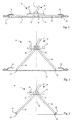
- the holder shown in Figures 1 and 2 consists essentially of three articulated interacting parts, namely a base plate 15 and two on the Base plate 15 hinged wings 19 and 20.
- the wings 19, 20 are two in Distance pivot axes 21,23 from an extended clamping position in a downward V-shaped foldable position.
- On the base plate 15 is a device 18 for articulating a stem, preferably in Shape of a universal joint, provided.
- the universal joint is with one Connection pin 17 equipped, on which a handle can be attached.
- a locking mechanism is used to keep the wings 19, 20 shown in FIG. 1 To connect the clamping position with the base plate 15 so that the wings 19, 20 in the stretched clamping position determined and not pivotable about the axes 21,23 are.
- the locking mechanism preferably consists of a movable bolt, which can be released with a release device 24 arranged on the base plate 15 is.
- FIGS Latch 43 arranged on the underside of the base plate.
- the base plate 15 can partially hollow for this purpose. be designed as a shell open at the bottom.
- latching means 41 (FIGS. 6 and 7) at a distance from the Swivel axes 21,23 formed.
- the locking means 41 are by at least one, preferably two pins 41 arranged at a distance from one another.
- the Bolt 43 is preferably flat and received flush in the base plate. He can have roughly the same dimensions as the base plate.
- the recesses 45 can one Have paragraph or an undercut 48, on which a pin 41 engage can.
- Two pegs 41 are at a distance from the longitudinal central axis on the wings arranged.
- the bolt 43 can have the shape of a double T (FIG. 12), wherein the recesses 45 are provided in the terminal head parts of the bolt 43 are.
- the bolt 43 can be moved relative to and parallel to the base plate 15.
- Spring means 47 which act between the base plate 15 and the bolt 43 hold the bolt 43 in the locked position.
- the release device respectively. includes the actuator 24 an actuating pin 55 which is movable perpendicular to the base plate 15.
- the Actuating pin 55 is arranged in an opening 76 in base plate 15.
- a feather 56 holds the actuating pin 55 in the starting position (FIG. 8).
- the spring 56 acts between the actuator head 54 and the base plate 15.
- the actuator pin 55 can - as will be explained in more detail below - in this way with the bolt 43 cooperate that the bolt 43 by advancing the actuating pin 55 in the Release position is displaceable. In the release position of the bolt 43, the pins arrive 41 from the engagement of the recesses 45, so that the wings 19, 20 from the Clamping position are pivotable.
- Figures 6 and 7 show a wing 19, 20 in more detail.
- the round holes 40 are in projections 39 intended.
- the projections 39 are in a preferred embodiment as Stops 26 formed, which in cooperation with the base plate 15 Limit the spreading angle of the wings 19.20.
- the spreading or Opening angle between base plate 15 and sash 19.20 maximum about 85 ° (s. Fig. 5).
- rollers 31 are provided at the opposite free (distal) end 27, 29 of the wings 19, 20 at the opposite free (distal) end 27, 29 of the wings 19, 20 there are two free rotatable rollers 31 are provided.
- the rollers 31 have the purpose of sliding the Ends 27, 29 via the mop cover 13 when the wings 19, 20 are inserted into the to facilitate opposing pockets 51, 52 of a mop cover.
- a recess 35 in the wings 19, 20 is arranged.
- a belt reel 37 is arranged between belt reel 37 and The edges of the recess 35 are slots 38, 38 'through which one Straps 33 of a mop cover can be looped.
- the straps 33 will preferably looped through the slots 38, 38 'such that the straps 33 are underneath the rolling means 31 extends.
- the rollers 31 and the belt roller 33 are each on one Axle bolt mounted, which from the bottom into a on the wing 19.20 trained axle bearing can be snapped.
- each pin 41 is symmetrical, so that it from both sides can work here equally with the bolt 43. Thanks to the symmetrical design of the peg can be the same wing 19.20 on each side of the holding part 15 are used.
- a link surface 49 is formed in the bolt 43, which can cooperate with the lower end of the actuating pin 55.
- the Actuating pin 55 has a head 54 at the upper end and one at the other end Sliding surface 57.
- the sliding surface 57 interacts with the link surface 49 in such a way that that when pushing the actuating pin 55 of the bolt 43 against the Spring force of the spring means 47 is moved into the release position.
- the Undercuts 46 come out of the engagement of the Recesses 45 so that the wings 19, 20 can be pivoted.
- the actuating pin 55 can be biased with a spring 56, as shown in FIG. in principle the spring means 47 acting on the bolt 43 can be dimensioned such that this both the bolt 43 and the actuating pin 55 in the starting position able to push back, so that an additional spring 56 is dispensed with can.
- the spring means 59 are preferably as an elastic pin protruding from the surface of the bolt 43 or tongues 59 formed, which in the tensioned position of the holder Preload between the base plate 15 and the wings 19, 20. As soon as the bolt 43 reaches the release position, the wings 19, 20 by the acting Spring force partially pivoted.
- the spring means 59 are integral with the bolt 43 trained. Counter-forms to the spring means can also be provided in the wings 19, 20 59 be formed, which cause the spring means only at its extreme Press the end onto the top of the wings 19, 20.
- 1 to 3 and 5 to 12 are the Pivot axes 21, 23 at a distance from one another and also at a distance from the underside arranged the base plate.
- the latter feature allows the wings to be flat train. In the tensioned position, the wings thus extend in one common plane on both sides of the swivel axes.
- the style attachment device is midway between the two Swivel axes 21, 23 are provided. By trained as stops 26 proximal ends of the wings 19, 20 remain in place when the holder 11 is raised an angle to the base plate 15.
- the exemplary embodiment according to FIG. 4 differs from the others Embodiments in that the wings 19, 20 around a common Pivot axis 22 are pivotable. They thus form in the folded position isosceles triangle.
- the holder 11 according to the invention can be used particularly advantageously in Connection with a mop cover 13, which is a band or a on the top Has straps 33 for connection to the holder 11.
- the mop cover 13 will Use attached to the holder 11 by the preferably two-part straps 33 through the spaces 38, 38 'are looped and the ends of the two belt parts e.g. be connected by means of a Velcro fastener.
- the wings 19, 20 are removed from the Locking released by the user releasing the device 24 by means of the foot pushes down. As a result, the bolt 43 is moved and the release position emotional. In this position, the spring means 59 press the wings 19, 20 and Base plate 15 apart.
- the folds Mop cover 13 in the middle. Hanging on the wings 19, 20, the mop cover in Rinse water swung and then wrung out in a ring without that he would have to be held in his hands. After wringing out the mop cover 13 is put back on the floor. In doing so he interprets himself, and the distal ends of the wings 19, 20 can be placed on the mop cover back become.
- the base plate 15 shown in FIGS. 10 to 12 essentially corresponds the base plate according to Figures 8 and 9. However, there are further details and alternative embodiments are shown.
- the base plate 15 has one cavity 71 open at the bottom, in which the bolt 43 is inserted.
- the cavity 71 has Areas with different depths.
- the end regions 73, 75 are formed deeper than the central region 77.
- Device 18 for attaching a stem is articulated. In the central area 77 acts the underside of the base plate 15 with the stops 26 of the wing 19.20 together.
- One end region 75 of the cavity 71 has in the longitudinal direction of the stenter a larger dimension than the other end region 73.
- a guide opening 76 in which the actuating pin 55 is guided.
- the central area 77 are on the Opposite sides of the base plate 15, two webs 62 are arranged.
- the bridges 62 each have two round holes 64 in which the axle bolts 61, 63 for fastening the Wings are stored.
- the axle bolts 61, 63 are only on one side in the web 62 stored, on the other hand they are cantilevered in the round holes 40 Grip wing 19.20.
- the two axle bolts arranged in the same web 62 are in one piece with a connecting the two axle bolts 61,63 Connection part made of plastic.
- the wings are e.g. brought into the tensioned position, and the Axle bolts 61, 63 from the outside into the round holes 40 and 64 put into it.
- the bolt has an extending in the direction of movement Bolt 83, which through an opening 84 in the wall of the base plate 15th passes through and in a accommodated in the opening 84 or Guide part 85 is mounted (Fig. 12).
- the bearing part 85 has a diameter 87, which in its width corresponds to the cross section of the bolt 83.
- the bolt 83 is passed through the opening 84 is inserted in the base plate 15.
- the latch 43 is then in the Holding part 16 inserted. Areas are left on the bolt 43, which allow the Bolt 43 in an extreme position beyond the release position next to the tabs 81 in to insert the cavity 71.
- the spring 47 is through the opening 84 on the bolt 83rd attached.
- the bearing part 85 By inserting the bearing part 85 into the opening 84, the spring 47 biased.
- the bearing part 85 snaps into the opening 84 so that it is the Transfers spring force to the edge of the base plate 15.
- the actuating pin 55 Before inserting the bolt into the cavity 71, the actuating pin 55 must be in the square guide opening 76 may be inserted.
- the actuating pin has Projections 88, which abut the edge of the guide opening 76, so that this after cannot slide out of the guide opening at the top. From above is for security of the actuating pin 55, a head 54 is connected to the actuating pin.
- the Actuating pin 55 has a bevelled sliding surface 49, which with a rectified backdrop surface 49 cooperates on the bolt.
- the bolt according to FIG. 12 also has the paragraphs 48, the bolt 83 and the spring means 59 still slide ribs 89, which cooperate with the inside of the cavity 71. Because the inside of the Cavity 71 is stepped, the sliding ribs are also of different heights.
- the holder can also be designed as a frame construction.
- the holder is basically made of metal, is plastic, e.g. Polyamide, as Manufacturing material preferred.
- plastic e.g. Polyamide
- the plastic parts preferably manufactured by injection molding.
Abstract
Description
Die Erfindung betrifft einen Halter gemäss Oberbegriff des Patentanspruchs 1.The invention relates to a holder according to the preamble of patent claim 1.
Halter mit zwei verschwenkbaren Flügeln ermöglichen das Einschlaufen der freien Flügelenden in zwei gegenüberliegende Einschlauftaschen, welche an einem Wischbezug ausgebildet sein können. Beim Verschwenken der Flügel in eine gestreckte Spannstellung wird der Abstand zwischen den Flügelenden vergrössert, wodurch der Wischbezug am Halter aufgespannt wird. Aus den Einschlauftaschen können die freien Enden der Flügel nur dann zurückgezogen werden, wenn die beiden zusammenklappbaren Flügel gegeneinander verschwenkt werden und so der Abstand zwischen deren freien Enden verkleinert wird.Holders with two swiveling wings allow the free ones to be looped in Wing ends in two opposite pockets, which on one Mop cover can be formed. When swinging the wings into one stretched clamping position the distance between the wing ends is increased, whereby the mop cover is stretched on the holder. From the pockets the free ends of the wings can only be retracted if the two collapsible wings can be pivoted against each other and so the Distance between their free ends is reduced.
Die US 5,926,896 offenbart einen Halter zum lösbaren Befestigen eines Mops. Der Halter besitzt zwei schwenkbar an einem Support angeordnete Platten, an deren äusseren Enden der Mop befestigbar ist. Die verschwenkbaren Platten sind mittels einer am Support angeordneten Arretiereinrichtung in einer koplanaren Lage feststellbar. Die Arretiereinrichtung besitzt einen länglichen, rundlichen Bolzen, welcher in einer Führungshülse verschiebbar geführt ist. Der Führungsbolzen ist mittels einer Feder vorgespannt und schlägt in der Arbeitsstellung des Halters an einem Stopp an, welcher an einer ersten der beiden verschwenkbaren Platten vorgesehen ist. Der Bolzen kann mittels eines Aktuators freigegeben werden, sodass die Platten verschwenkt werden können. Dabei verschiebt sich der Bolzen in Richtung der Federkraft von einer zurückgezogenen Anschlagstellung in Federkraftrichtung in eine teilweise entspannte Lösestellung. Sobald der eine Flügel teilweise verschwenkt ist, kann sich der Bolzen in die Lösestellung verschieben, in welcher auch der zweite Flügel freigegeben ist.US 5,926,896 discloses a holder for releasably attaching a pug. The Holder has two plates, which are pivotably arranged on a support, on the support outer ends of the mop can be attached. The swiveling plates are by means of a locking device arranged on the support in a coplanar position ascertainable. The locking device has an elongated, rounded bolt, which is slidably guided in a guide sleeve. The guide pin is biased by a spring and strikes in the working position of the holder a stop at which on a first of the two pivotable plates is provided. The bolt can be released using an actuator so that the plates can be swiveled. The bolt moves in Direction of spring force from a retracted stop position in Spring force direction in a partially relaxed release position. As soon as one wing is partially pivoted, the bolt can move into the release position, in which is also the second wing released.
Der Aktuator besteht aus einem Pedal, welches mittels eines Scharniers schwenkbar an der ersten Platte befestigt ist. Eine am Pedal vorgesehene Blattfeder dient dazu, eine Vorspannung zwischen der ersten Platte und dem Support zu erzeugen. Beim Niederdrücken des Pedals kann der Bolzen nach oben ausweichen, und die Blattfeder erzwingt ein Verschwenken der ersten Platte im Uhrzeigersinn und damit eine Freigabe des ersten Flügels.The actuator consists of a pedal that can be pivoted by means of a hinge is attached to the first plate. A leaf spring provided on the pedal serves to to create a preload between the first plate and the support. At the Depressing the pedal can deflect the bolt upwards, and that Leaf spring forces the first plate to pivot clockwise and thus a release of the first wing.
Es ist Aufgabe der Erfindung einen Halter für Wischbezüge zu schaffen, welcher einfach und kostengünstig in der Herstellung ist. Ein weiteres Ziel ist es, einen Halber bereitzustellen, mit welchem ein Wischbezug rasch aufgespannt werden kann. Der Wischbezug sollte zum Aufspannen nicht in die Hände genommen werden müssen. Ein weiteres Ziel ist es, einen Halter zur Verfügung zu stellen, welcher erlaubt, einen Wischbezug auszuwringen, ohne diesen vom Halter zu nehmen.It is an object of the invention to provide a holder for mop covers, which is simple and inexpensive to manufacture. Another goal is to get one For the sake of providing, with which a mop cover can be quickly opened can. The mop cover should not be held in your hands when opening Need to become. Another goal is to provide a holder which allows you to wring out a mop cover without closing it from the holder to take.
Erfindungsgemäss wird dies durch einen Halter gemäss Kennzeichen des Patentanspruchs 1 realisiert. Durch direktes Zusammenwirken des Betätigungsorgans mit dem Riegel kann bei dessen Betätigung eine Verschiebung des Riegels entgegen der Kraft der ersten Federmittel in eine Löseposition bewirkt werden, sodass die Flügel des Halters in die Faltstellung verschwenkt werden können. Im Unterschied zur US 5,926,896 wird der Riegel durch das Betätigungsorgan direkt und entgegen der Federkraft in die Löseposition verschoben.According to the invention, this is carried out by a holder according to the characteristics of the Claim 1 realized. Through direct interaction of the Actuator with the bolt can move when actuated of the bolt against the force of the first spring means in a release position so that the wings of the holder are pivoted into the folded position can. In contrast to US 5,926,896, the bolt is made by Actuator directly and against the spring force in the release position postponed.
Durch das Vorsehen einer Grundplatte kann der Halter im wesentlichen symmetrisch ausgebildet sein, was Vorteile beim Einführen der Flügelenden in die Taschen eines Wischbezugs mit sich bringt. Der erfindungsgemässe Halter hat auch den Vorteil, dass er kostengünstig herstellbar ist.By providing a base plate, the holder can essentially be formed symmetrically, which advantages when inserting the wing ends in the Brings pockets of a mop cover with it. The holder according to the invention also has the advantage that it is inexpensive to manufacture.
Vorteilhaft weisen das Betätigungsorgan und der Riegel miteinander zusammenwirkende Kulissenflächen auf. Die Kulissenflächen haben den Vorteil, dass die Verschieberichtungen des Betätigungsorgans und des Riegels unterschiedlich sein können. Zweckmässigerweise sind an der Grundplatte mindestens zwei in Abstand voneinander angeordnete Führungen zur Führung des Riegels ausgebildet. Diese sorgen für eine gute Führung des Riegels. Vorzugsweise ist der Riegel flach und an gegenüberliegenden Seiten an der Grundplatte geführt. Die an den gegenüberliegenden Seiten der Grundplatte vorhandenen Führungen können durchgehend oder unterbrochen sein. Wenn an gegenüberliegenden Seiten der Grundplatte mindestens zwei in Abstand voneinander angeordnete Führungen vorgesehen sind, so hat dies den Vorteil, dass der Riegel bei entsprechender Ausführung von unten her in die Führungsbahn eingeführt werden kann.The actuating member and the latch advantageously point to one another interacting backdrop areas. The backdrop surfaces have the advantage that the displacement directions of the actuator and the latch can be different. Appropriately are on the base plate at least two spaced guides for guiding the Riegel trained. These ensure that the bolt is properly guided. Preferably the bolt is flat and guided on opposite sides of the base plate. The guides on the opposite sides of the base plate can be continuous or interrupted. If on opposite sides the base plate at least two spaced guides are provided, this has the advantage that the bolt with appropriate Execution can be inserted from below into the guideway.
Gemäss einer besonders bevorzugten Ausführungsform ist der Riegel in der vorzugsweise hohlen Grundplatte aufgenommen oder an der Unterseite der Grundplatte angeordnet. Die Grundplatte kann von unten her offen ausgebildet sein, resp. eine Kavität zur Aufnahme des Riegels aufweisen. Vorteilhaft wirken der Riegel und die Flügel in der Arretierstellung formschlüssig zusammen. Zu diesem Zweck können die Flügel Einrastmittel aufweisen, welche mit entsprechenden Aussparungen am Riegel formschlüssig zusammenwirken. In einer bevorzugten Ausführungsform sind die Einrastmittel Zapfen, welche in der Spannstellung mit entsprechenden Vorsprüngen oder Ausnehmungen am Halter formschlüssig zusammenwirken können. Vorzugsweise sind pro Flügel quer zur Längserstreckung des Halters zwei in Abstand voneinander angeordnete Einrastmittel vorgesehen. Dies hat den Vorteil, dass Flügel und Grundplatte in der Spannstellung praktisch spielfrei zueinander fixiert sind.According to a particularly preferred embodiment, the bolt is in the preferably hollow base plate or added to the bottom of the Base plate arranged. The base plate can be open from below, respectively. have a cavity for receiving the bolt. The have an advantageous effect Bolts and the wings in the locking position form-fit together. To this For this purpose, the wings can have latching means, which correspond with corresponding Interactively engage recesses on the bolt. In a preferred one Embodiment are the locking means pegs, which in the clamping position corresponding projections or recesses on the holder form-fitting can work together. Per wing are preferably transverse to the longitudinal extent the holder is provided with two latching means spaced apart from one another. This has the advantage that the wing and base plate are practical in the clamping position are fixed to each other without play.
Vorteilhaft weist die Grundplatte ein Rahmenteil und einen relativ zur Grundplatte verschiebbaren Riegel auf. Diese Ausführungsform hat den Vorteil, dass durch Verschieben des Riegels beide Flügel gleichzeitig gelöst werden können. Der bewegliche Riegel ist zwischen einer Löseposition und einer Arretierstellung verschiebbar. Vorzugsweise sind an beiden Flügeln Einrastmittel vorhanden, welche mit dem Riegel zusammenwirken können. Durch ein Verschieben des Riegels wird eine daran ausgebildete Einrastkante verschoben, an welcher in der Arretierstellung des Riegels die Einrastmittel einrasten, sodass ein Verschwenken der Flügel verunmöglicht ist. Vorteilhaft sind erste Federmittel vorhanden, welche den Riegel in die Arretierstellungvorspannen. In der Arretierstellung des Riegels und Spannstellung der Flügel sind letztere fest mit der Grundplatte verbunden.The base plate advantageously has a frame part and one relative to the base plate sliding latch. This embodiment has the advantage that Moving the latch both wings can be released at the same time. The movable latch is between a release position and a locking position displaceable. There are preferably latching means on both wings, which can interact with the bolt. By moving the latch a snap-in edge formed thereon, on which in the locking position of the bolt engage the locking means, so that the wing can pivot is impossible. First spring means are advantageously present, which lock the bolt preload the locking position. In the locking position of the bolt and The clamping position of the wings are firmly connected to the base plate.
Um den Riegel zum Ausklinken der Einrastmittel in eine Löseposition zu verschieben, ist vorteilhaft eine Lösevorrichtung resp. ein Betätigungsorgan vorhanden. Vorteilhaft ist das Betätigungsorgan ein Betätigungsstift, welcher senkrecht oder in einem Winkel zur Verschieberichtung des Riegels beweglich ist. Der Riegel selbst ist vorzugsweise in Längsrichtung des Spannrahmens beweglich. Vorteilhaft wirken Betätigungsstift und Riegel über Gleitflächen kullissenartig zusammen.To release the latch in a release position move, a release device is advantageous. an actuator available. The actuating member is advantageously an actuating pin, which is movable vertically or at an angle to the direction of displacement of the bolt. The bolt itself is preferably movable in the longitudinal direction of the tenter. The actuating pin and bolt advantageously act like a pillow over sliding surfaces together.
Wenn auch nicht zwingend erforderlich, so sind die beiden Flügel doch mit Vorteil im Wesentlichen gleich, vorzugsweise identisch, ausgebildet. Dies hat den Vorteil, dass der Halter in der Faltstellung bezüglich einer vertikalen Mittelebene symmetrisch ist. Durch eine identische Ausbildung der Flügel können die Produktionskosten niedrig gehalten werden. Bei Flügeln aus Kunststoff können damit Formkosten gespart werden. Die Flügel können um eine gemeinsame Achse oder vorzugsweise um zwei in Abstand zueinander angeordnete Achsen verschwenkbar sein. Diese sind vorteilhaft parallel zueinander gerichtet.Although not absolutely necessary, the two wings are an advantage essentially the same, preferably identical. This has the advantage that the holder is in the folded position with respect to a vertical central plane is symmetrical. By an identical formation of the wings, the Production costs can be kept low. For plastic wings so that molding costs are saved. The wings can be on a common axis or preferably about two spaced axes be pivotable. These are advantageously directed parallel to one another.
Vorteilhaft sind Mittel vorgesehen, die gewährleisten, dass in der Faltstellung der Abstand zwischen den Flügeln an deren Anlenkstelle an der Grundplatte kleiner ist als an deren freien Enden. Diese Mittel können durch wenigstens einen die Schwenkbewegung zwischen Grundplatte und Flügel begrenzenden Anschlag gebildet sein. Es kann aber beispielsweise auch eine zwischen den Flügeln wirkende Feder vorgesehen sein, welche die Schwenkbewegung begrenzt. Bei dieser Ausführungsform lassen sich bei Bedarf die freien Enden der Flügel entgegen der wirkenden Federkraft noch näher zusammendrücken. Es können auch Haltegurten zwischen Grundplatte und den Flügeln vorhanden sein, welche die Flügel in der Faltstellung in einem bestimmten Winkel halten. Die oben beschriebenen Ausführungsformen haben den Vorteil, dass die an der Grundplatte angelenkten Flügel in der Faltstellung in einem spitzen Winkel zueinander orientiert sind. Wird der Halter in Faltstellung auf den Wischbezug abgestellt, so spreizen sich die Flügel praktisch selbsttätig unter der Wirkung des Eigengewichts des Halters. Nötigenfalls kann das Verschwenken der Flügel durch Druck auf die Grundplatte unterstützt werden. Vorteilhaft ist am freien Ende eines Flügels ein Abrollmittel vorhanden. Durch das Vorsehen wenigstens eines Abrollmittels, z.B. einer Rolle, Gleitkufe etc., kann der Reibwiderstand der Flügelenden auf dem Untergrund stark reduziert werden.Means are advantageously provided to ensure that in the folded position Distance between the wings at their articulation point on the base plate is smaller than at their free ends. These funds can be obtained through at least one Swinging movement between base plate and sash limiting stop be educated. But it can, for example, also act between the wings Spring may be provided, which limits the pivoting movement. At this Embodiment, if necessary, the free ends of the wings against the compress the acting spring force even closer. Seat belts can also be used be present between the base plate and the wings, which the wings in the Hold the folding position at a certain angle. The ones described above Embodiments have the advantage that the articulated on the base plate Wings are oriented at an acute angle to each other in the folded position. Becomes If the holder is placed in the folded position on the mop cover, the wings will spread practically automatically under the effect of the weight of the holder. If necessary, can support the pivoting of the wings by pressing on the base plate become. A rolling means is advantageously present at the free end of a wing. By providing at least one rolling means, e.g. a roller, skid etc., the frictional resistance of the wing tips on the ground can be greatly reduced become.
Die Grundplatte und/oder die Anlenkstellen der Flügel sind vorzugsweise derart ausgebildet, dass die entriegelten Flügel bei angehobenem Halter zueinander eine nach unten V-förmig geöffnete Faltstellung einnehmen. Am proximalen Ende der Flügel ist dazu vorteilhaft ein Anschlag ausgebildet ist, welcher mit der Grundplatte zusammenwirken kann und den Öffnungswinkel zwischen Grundplatte und Flügel in der Faltstellung auf einen Winkel < 90°, vorzugsweise < 85° begrenzt.The base plate and / or the articulation points of the wings are preferably such formed that the unlocked wings to each other when the holder is raised Assume the fold-open position downwards in a V-shape. At the proximal end of the For this purpose, the wing is advantageously designed as a stop which is connected to the base plate can interact and the opening angle between the base plate and sash limited to an angle of <90 °, preferably <85 ° in the folded position.
Vorteilhaft ist zum Einschlaufen einer Gurte eines Wischbezuges eine Einschlaufvorrichtung an den Flügeln vorhanden. Dies erlaubt, einen Wischbezug mit einer Gurte an den Halter zu binden. Die Gurte besteht dabei zweckmässigerweise aus zwei Gurtstücken, deren eine Gurtstückenenden an gegenüberliegenden Seiten des Wischbezugs angenäht sind. Die anderen Gurtstückenenden können durch die Einschlaufvorrichtungen an den Flügel geschlauft und lösbar miteinander verbindbar sein. Bei durchgeschlauften Gurten bleibt der Wischbezug nach dem Ausschlaufen der freien Flügelenden mit der Gurte an den Flügeln hängen. Wegen der gleich langen Flügel wird der Wischbezug bei geöffnetem Halter in der Mitte gefaltet und kann so in eine Wringe zum Auswringen gegeben werden, ohne dass er dazu vom Halter genommen werden müsste. Die Einschlaufvorrichtung ist vorteilhaft durch mindestens einen Schlitz, vorzugsweise zwei in Abstand voneinander angeordnete Schlitze gebildet, welche in Abstand zu den distalen Enden der Flügel vorhanden sind. One is advantageous for looping in a belt of a mop cover Loop device on the wings. This allows a mop cover to tie with a strap to the holder. The straps are there expediently from two pieces of belt, one end of the piece of belt opposite sides of the mop cover are sewn on. The others Belt piece ends can through the loop devices on the wing looped and releasably connectable. With belts running through the mop cover remains after the free wing ends have run out with the belts hanging on the wings. Because of the equally long wings, the mop cover is open holder folded in the middle and can be wrung into a ring be given without having to be removed from the holder. The Infeed device is advantageous through at least one slot, preferably two spaced apart slots are formed, which are spaced apart the distal ends of the wings are present.
Vorteilhaft sind die Flügel in der Spannstellung in Richtung Faltstellung vorgespannt. In einer vorteilhaften Ausführungsform sind zweite Federmittel zwischen der Grundplatte und wenigstens einem Flügel vorhanden, um den gelösten Flüge, d.h. wenn der Riegel sich in der Lösestellung befindet, aus der Spannstellung zu verschwenken. Durch die vorgesehenen Federmittel springen die Flügel selbsttätig aus der Spannstellung, sobald der Riegel in die Löseposition gebracht ist. Die zweiten Federmittel können am Riegel oder an den Flügeln angeordnet oder ausgebildet sein.The wings are advantageous in the tensioned position in the direction of the folded position biased. In an advantageous embodiment there are second spring means between the base plate and at least one wing to the solved flights, i.e. when the latch is in the release position, from the Swivel the clamping position. The jump through the provided spring means Sash automatically out of the cocking position as soon as the latch in the release position brought. The second spring means can be on the latch or on the wings be arranged or formed.
Gemäss einem anderen unabhängigen Aspekt der vorliegenden Erfindung ist auch
ein Halter gemäss Oberbegriff von Anspruch 24 beansprucht, welcher dadurch
charakterisiert ist, dass dass an der Grundplatte oder am Riegel Federmittel
vorgesehen sind, welche in der Spannstellung eine in Richtung Faltstellung wirkende
Vorspannung zwischen der Grundplatte und den Flügeln bewirken.. Dieser Halter
hat den Vorteil, dass die Flügel sofort aus der Spannstellung springen, sobald die
Verbindungsmittel gelöst sind. Weitere vorteilhafte Ausführungsformen sind in den
Unteransprüche definiert.According to another independent aspect of the present invention
claimed a holder according to the preamble of
Gemäss einem weiteren unabhängigen Aspekt der vorliegenden Erfindung ist ein
erfindungsgemässer Halter gemäss Oberbegriff von Anspruch 26 ist dadurch
charakterisiert, dass an den freien (distalen) Enden der Flügel Rollen oder Gleitmittel
vorgesehen sind. Dieser Halter hat den Vorteil, dass die Flügel sich selbsttätig in die
Spannstellung spreizen, wenn die in einem Winkel zur Vertikalen sich befindlichen
Flügel auf den Boden abgestellt werden. Weitere vorteilhafte Ausführungsformen
sind in den Unteransprüchen definiert.According to a further independent aspect of the present invention, a
holder according to the preamble of
Anhand der Figuren sind verschiedene Ausführungsbeispiele der Erfindung näher beschrieben. Diese zeigen schematisch:
- Fig. 1
- ein erstes Ausführungsbeispiel eines erfindungsgemässen Halters in Spannstellung mit zwei an einer Grundplatte angeordneten, verschwenkbaren Flügeln und einem aufgespannten Wischbezug;
- Fig. 2
- den Halter mit Wischbezug nach Figur 1 mit verschwenkten Flügeln (Faltstellung);
- Fig. 3
- den Halter wie in Figur 2, jedoch mit Abrollmitteln an den Flügelenden;
- Fig. 4
- ein zweites Ausführungsbeispiel eines Halters mit einer gemeinsamen Achse für beide Flügel;
- Fig. 5
- den Halter nach Figur 3 mit Einschlaufmitteln für eine Wischbezuggurte und einem Wischbezug mit einer solchen Gurte;
- Fig. 6
- eine Draufsicht auf einen Flügel des Halters gemäss Figur 5;
- Fig. 7
- einen Längsschnitt durch den Flügel gemäss Figur 6;
- Fig. 8
- einen Längsschnitt durch eine Grundplatte;
- Fig. 9
- eine Untersicht der Grundplatte nach Figur 8;
- Fig. 10
- eine Untersicht einer bevorzugter Ausführungsform einer Grundplatte mit Riegel,
- Fig. 11
- eine Untersicht der Grundplatte gemäss Fig. 10, ohne Riegel,
- Fig. 12
- eine Aufsicht auf den Riegel gemäss Fig. 10.
- Fig. 1
- a first embodiment of a holder according to the invention in the clamping position with two pivotable wings arranged on a base plate and a stretched mop cover;
- Fig. 2
- the holder with mop cover according to Figure 1 with pivoted wings (folded position);
- Fig. 3
- the holder as in Figure 2, but with rolling means at the wing ends;
- Fig. 4
- a second embodiment of a holder with a common axis for both wings;
- Fig. 5
- the holder of Figure 3 with loop means for a mop cover straps and a mop cover with such straps;
- Fig. 6
- a plan view of a wing of the holder according to Figure 5;
- Fig. 7
- a longitudinal section through the wing according to Figure 6;
- Fig. 8
- a longitudinal section through a base plate;
- Fig. 9
- a bottom view of the base plate of Figure 8;
- Fig. 10
- a bottom view of a preferred embodiment of a base plate with latch,
- Fig. 11
- 10 a bottom view of the base plate according to FIG. 10, without latch,
- Fig. 12
- a top view of the bolt according to FIG. 10.
Der in den Figuren 1 und 2 gezeigte Halter besteht im Wesentlichen aus drei
gelenkig zusammenwirkenden Teilen, nämlich einer Grundplatte 15 und zwei an der
Grundplatte 15 angelenkten Flügeln 19 und 20. Die Flügel 19, 20 sind um zwei in
Abstand angeordnete Schwenkachsen 21,23 von einer gestreckten Spannstellung in
eine nach unten V-förmig offene Faltstellung verschwenkbar. Auf der Grundplatte 15
ist eine Vorrichtung 18 zur gelenkigen Anbringung eines Stiels, vorzugsweise in
Gestalt eines Kreuzgelenks, vorgesehen. Das Kreuzgelenk ist mit einem
Verbindungszapfen 17 ausgerüstet, an welchem ein Stiel befestigbar ist.The holder shown in Figures 1 and 2 consists essentially of three
articulated interacting parts, namely a
Eine Arretiermechanik dient dazu, die Flügel 19,20 in der in Fig. 1 dargestellten
Spannstellung mit der Grundplatte 15 zu verbinden, sodass die Flügel 19,20 in der
gestreckten Spannstellung festgestellt und nicht um die Achsen 21,23 verschwenkbar
sind. Die Arretiermechanik besteht vorzugsweise aus einem beweglichen Riegel,
welcher mit einer auf der Grundplatte 15 angeordneten Lösevorrichtung 24 lösbar
ist. Gemäss den in den Figuren 8 bis 12 gezeigten Ausführungsbeispielen ist der
Riegel 43 an der Unterseite der Grundplatte angeordnet. Die Grundplatte 15 kann zu
diesem Zweck teilweise hohl resp. als nach unten offene Schale ausgebildet sein. An
der Oberseite der Flügel 19,20 sind Einrastmittel 41 (Fig. 6 und 7) in Abstand zu den
Schwenkachsen 21,23 ausgebildet. Die Einrastmittel 41 sind durch wenigstens einen,
vorzugsweise zwei in Abstand voneinander angeordnete Zapfen 41 gebildet. Der
Riegel 43 ist vorzugsweise flach und in der Grundplatte bündig aufgenommen. Er
kann in etwa die gleichen Dimensionen wie die Grundplatte haben. Im Riegel 43 sind
mit den Zapfen 41 formschlüssig zusammenwirkende Aussparungen 45 ausgebildet,
in welchen die Zapfen 41 einrasten können. Die Aussparungen 45 können einen
Absatz oder eine Hinterschneidung 48 aufweisen, an welcher ein Zapfen 41 einrasten
kann. Je zwei Zapfen 41 sind in Abstand von der Längsmittelachse auf den Flügeln
angeordnet. Der Riegel 43 kann die Gestalt eines Doppel-T's haben (Fig. 12), wobei
die Aussparungen 45 in den endständigen Kopfteilen des Riegels 43 vorgesehen
sind.A locking mechanism is used to keep the
Der Riegel 43 ist relativ und parallel zur Grundplatte 15 verschiebbar. Federmittel 47,
welche zwischen der Grundplatte 15 und dem Riegel 43 wirken, halten den Riegel 43
in der Arretierstellung. Die Lösevorrichtung resp. das Betätigungsorgan 24 umfasst
einen Betätigungsstift 55, welcher senkrecht zur Grundplatte 15 beweglich ist. Der
Betätigungsstift 55 ist in einer Öffnung 76 der Grundplatte 15 angeordnet. Eine Feder
56 hält den Betätigungsstift 55 in der Ausgangsposition (Fig. 8). Die Feder 56 wirkt
zwischen dem Betätigungskopf 54 und der Grundplatte 15. Der Betätigungsstift 55
kann - wie weiter unten noch näher erklärt wird - derart mit dem Riegel 43
zusammenwirken, dass der Riegel 43 durch Vorschub des Betätigungsstifts 55 in die
Lösestellung verschiebbar ist. In der Lösestellung des Riegels 43 gelangen die Zapfen
41 aus dem Eingriff der Ausnehmungen 45, sodass die Flügel 19,20 aus der
Spannstellung verschwenkbar sind.The
Die Figuren 6 und 7 zeigen einen Flügel 19,20 näher im Detail. Am proximalen Ende
des Flügels sind zwei als Achslager dienende Rundlöcher 40 für die Aufnahme je
eines Achsstifts 61,63 ausgebildet. Die Rundlöcher 40 sind in Vorsprüngen 39
vorgesehen. Die Vorsprünge 39 sind in einer bevorzugten Ausführungsform als
Anschläge 26 ausgebildet, welche im Zusammenwirken mit der Grundplatte 15 den
Spreizwinkel der Flügel 19,20 begrenzen. Vorzugsweise ist der Spreiz- oder
Öffnungswinkel zwischen Grundplatte 15 und Flügel 19,20 maximal ungefähr 85° (s.
Fig. 5).Figures 6 and 7 show a
Am gegenüberliegenden freien (distalen) Ende 27,29 der Flügel 19,20 sind zwei frei
drehbare Rollen 31 vorgesehen. Die Rollen 31 haben den Zweck, das Gleiten der
Enden 27,29 über den Wischbezug 13 beim Einführen der Flügel 19,20 in die
einander gegenüberliegenden Taschen 51,52 eines Wischbezugs zu erleichtern.
Anschliessend an die Rollmittel 31 sind in den Flügeln 19,20 je eine Ausnehmung 35
vorgesehen, in welcher eine Gurtrolle 37 angeordnet ist. Zwischen Gurtrolle 37 und
den Rändern der Ausnehmung 35 sind Schlitze 38,38' vorhanden, durch welche eine
Gurte 33 eines Wischbezugs geschlauft werden kann. Die Gurte 33 wird
vorzugsweise so durch die Schlitze 38,38' geschlauft, dass sich die Gurte 33 unter
dem Rollmittel 31 erstreckt. Die Rollen 31 und die Gurtrolle 33 sind je auf einem
Achsbolzen gelagert, welcher von der Unterseite her in ein am Flügel 19,20
ausgebildetes Achslager einschnappbar ist.At the opposite free (distal)
Auf der Oberseite der Flügel 19,20 sind vorzugsweise zwei als Zapfen 41
ausgebildete Einrastmittel vorgesehen. Die Zapfen 41 wirken mit dem Riegel 43 (Fig.
8 und 9) der Grundplatte 15 zusammen. Die Zapfen 41 haben Hinterschneidungen
46, welche in den entsprechenden Aussparungen 45 im Riegel 43 einrasten können.
Die Aussparungen 45 können dazu, wie in Fig. 8 dargestellt, eine Hinterschneidung
48 haben. Jeder Zapfen 41 ist symmetrisch ausgebildet, so dass er von beiden Seiten
her gleichermassen mit dem Riegel 43 zusammenwirken kann. Dank der
symmetrischen Ausbildung der Zapfen kann der gleiche Flügel 19,20 auf jeder Seite
des Halteteils 15 eingesetzt werden. On the top of the
An der Grundplatte 15 sind Stege 62 mit Rundlöchern 64 zur Aufnahme von
Achsbolzen 61,63 vorgesehen. Beim zusammengesetzten Halter 11 erstrecken sich die
Achsbolzen 61,63 durch die als Achslager dienenden Rundlöcher 40 der Flügel 19,20.
Zwischen den gegenüberliegenden Stegen 62 ist ein Zwischenraum 65 vorhanden, in
welchem sich das Mittelteil 66 des vorzugsweise einstückigen Riegels 43 erstrecken
kann.On the
Im Bereich des Betätigungstifts 55 ist im Riegel 43 eine Kulissenfläche 49 ausgebildet,
welche mit dem unteren Ende des Betätigungsstifts 55 zusammenwirken kann. Der
Betätigungsstift 55 besitzt am oberen Ende einen Kopf 54 und am anderen Ende eine
Gleitfläche 57. Die Gleitfläche 57 wirkt mit der Kulissenfläche 49 derart zusammen,
dass beim Nachuntendrücken des Betätigungsstifts 55 der Riegel 43 entgegen der
Federkraft der Federmittel 47 in die Lösestellung verschoben wird. In der
Lösestellung gelangen die Hinterschneidungen 46 aus dem Eingriff der
Ausnehmungen 45, sodass die Flügel 19,20 verschwenkbar sind. Der Betätigungsstift
55 kann wie in Figur 6 dargestellt mit einer Feder 56 vorgespannt sein. Grundsätzlich
kann das auf den Riegel 43 wirkende Federmittel 47 so dimensioniert sein, dass
dieses sowohl den Riegel 43 als auch den Betätigungsstift 55 in die Ausgangsstellung
zurückzuschieben vermag, sodass auf eine zusätzliche Feder 56 verzichtet werden
kann.In the area of the
Analog zum Betätigungsstift 55 ist auch an den Zapfen 41 eine Gleitfläche 58
ausgebildet. Die Gleitfläche 58 kann mit den Rändern der Ausnehmungen 45 derart
zusammenwirken, dass beim Verspreizen der Flügel 19,20, z.B. durch eine senkrecht
von oben auf den Halter wirkende Kraft, der Riegel 43 in Richtung des Pfeils 60
zurückgestossen wird. Sobald die Hinterschneidungen 46 des Zapfens 45 in Eingriff
mit den Absätzen 48 gelangen, schnappt der durch die Federmittel 47 vorgespannte
Riegel 43 selbsttätig in die Arretierposition.Analogous to the
Damit die Flügel 19,20 beim Betätigen des Betätigungshebels 24 selbsttätig teilweise
in die Faltstellung springen, sind zwischen der Grundplatte 15 resp. dem Riegel 43
und den Flügeln 19,20 wirkende Federmittel 59 vorgesehen. Die Federmittel 59 sind
vorzugsweise als elastische, aus der Oberfläche des Riegels 43 herausragende Zapfen
oder Zungen 59 ausgebildet, welche in der Spannstellung des Halters eine
Vorspannung zwischen der Grundplatte 15 und den Flügeln 19,20 bewirken. Sobald
der Riegel 43 die Lösestellung erreicht, werden die Flügel 19,20 durch die wirkende
Federkraft teilweise verschwenkt. Die Federmittel 59 sind einstückig mit dem Riegel
43 ausgebildet. In den Flügeln 19,20 können auch Gegenformen zu den Federmitteln
59 ausgebildet sein, die bewirken, dass die Federmittel lediglich an ihrem äussersten
Ende auf die Oberseite der Flügel 19,20 pressen.So that the
In den Ausführungsbeispielen gemäss Fig. 1 bis 3 und 5 bis 12 sind die Schwenkachsen 21,23 in Abstand voneinander und auch in Abstand zur Unterseite der Grundplatte angeordnet. Durch letzteres Merkmal ist es möglich, die Flügel flach auszubilden. In der Spannstellung erstrecken sich somit die Flügel in einer gemeinsamen Ebene zu beiden Seiten der Schwenkachsen.1 to 3 and 5 to 12 are the Pivot axes 21, 23 at a distance from one another and also at a distance from the underside arranged the base plate. The latter feature allows the wings to be flat train. In the tensioned position, the wings thus extend in one common plane on both sides of the swivel axes.
Die Vorrichtung zum Anbringen eines Stils ist in der Mitte zwischen den beiden
Schwenkachsen 21,23 vorgesehen. Durch die als Anschläge 26 ausgebildeten
proximalen Enden der Flügel 19,20 verharren diese bei angehobenem Halter 11 in
einem Winkel zur Grundplatte 15.The style attachment device is midway between the two
Swivel axes 21, 23 are provided. By trained as
Das Ausführungsbeispiel gemäss Figur 4 unterscheidet sich von den anderen
Ausführungsbeispielen dadurch, dass die Flügel 19,20 um eine gemeinsame
Schwenkachse 22 verschwenkbar sind. Sie bilden somit in der Faltstellung ein
gleichschenkliges Dreieck.The exemplary embodiment according to FIG. 4 differs from the others
Embodiments in that the
Der erfindungsgemässe Halter 11 kann besonders vorteilhaft eingesetzt werden in
Verbindung mit einem Wischbezug 13, welcher an der Oberseite ein Band oder eine
Gurte 33 zur Verbindung mit dem Halter 11 aufweist. Der Wischbezug 13 wird beim
Gebrauch am Halter 11 befestigt, indem die vorzugsweise zweiteilige Gurte 33 durch
die Zwischenräume 38,38' geschlauft wird und die Enden der beiden Gurtenteile z.B.
mittels eines Klettenverschlusses verbunden werden.The
Zum Spülen eines verschmutzten Wischbezugs werden die Flügel 19,20 aus der
Arretierung gelöst, indem der Benutzer die Lösevorrichtung 24 mittels des Fusses
nach unten drückt. Dadurch wird der Riegel 43 verschoben und die Lösestellung
bewegt. In dieser Position drücken die Federmittel 59 die Flügel 19,20 und die
Grundplatte 15 auseinander. Beim Anheben des Halters 11 faltet sich der
Wischbezug 13 in der Mitte. An den Flügeln 19,20 hängend kann der Wischbezug im
Spülwasser geschwenkt und danach in einer Wringe ausgewrungen werden, ohne
dass er dazu in die Hände genommen werden müsste. Nach dem Auswringen wird
der Wischbezug 13 wieder auf den Boden gelegt. Dabei legt er sich aus, und die
distalen Enden der Flügel 19,20 können auf dem Wischbezugrücken abgelegt
werden. Da die Flügel 19,20 bereits teilweise gespreizt sind, verschwenken sich diese
aufgrund des Eigengewichts des Halters und des geringen Reibwiderstands der
freien Bügelenden 27,29 fast selbsttätig. Dabei schieben sich die freien Enden 27,29 in
die Taschen 51,52 des Wischbezugs. Durch einen leichten Druck auf die Grundplatte
15 schnappen die Zapfen 41 in den Aussparungen 35 ein.To rinse a dirty mop cover, the
Die in den Figuren 10 bis 12 dargestellte Grundplatte 15 entspricht im Wesentlichen
der Grundplatte gemäss den Figuren 8 und 9. Es sind jedoch weitere Einzelheiten
und alternative Ausführungsformen dargestellt. Die Grundplatte 15 besitzt eine
unten offene Kavität 71, in der der Riegel 43 eingelegt ist. Die Kavität 71 besitzt
Bereiche mit unterschiedlicher Tiefe. Die Endbereiche 73,75 sind tiefer ausgebildet als
der Mittelbereich 77. Auf der Oberseite der Grundplatte 15 ist im Mittelbereich 77 die
Vorrichtung 18 zum Anbringen eines Stiels angelenkt ist. Im Mittelbereich 77 wirkt
die Unterseite der Grundplatte 15 mit den Anschlägen 26 der Flügel 19,20
zusammen.The
Der eine Endbereich 75 der Kavität 71 besitzt in Längsrichtung des Spannrahmens
eine grössere Abmessung als der andere Endbereich 73. Im grösseren Endbereich 75
ist in der Oberseite der Grundplatte 15 eine Führungsöffnung 76 ausgebildet, in der
der Betätigungsstift 55 geführt ist. Im Mittelbereich 77 sind auf den
gegenüberliegenden Seiten der Grundplatte 15 zwei Stege 62 angeordnet. Die Stege
62 besitzen je zwei Rundlöcher 64, in denen die Achsbolzen 61,63 zur Befestigung der
Flügel gelagert sind. Die Achsbolzen 61,63 sind lediglich auf einer Seite im Steg 62
gelagert, auf der anderen Seite sind sie auskragend, um in die Rundlöcher 40 am
Flügel 19,20 zu greifen. Die beiden im gleichen Steg 62 angeordneten Achsbolzen
sind einstückig mit einem die beiden Achsbolzen 61,63 verbindenden
Verbindungsteil aus Kunststoff hergestellt. Zum Anlenken der Flügel 19,20 an die
Grundplatte 15 werden die Flügel z.B. in die Spannstellung gebracht, und die
Achsbolzen 61,63 von der Aussenseite her in die Rundlöcher 40 und 64
hineingesteckt.One
Am Öffnungsrand der Kavität 71 sind weiter vier Laschen 81 angeordnet, die in die
Öffnung der Kavität 71 hineinreichen und als Führungen für den Riegel 43 dienen.
Der Riegel 43 ist zwischen den Laschen 81 und der Oberseite der Grundplatte 15
angeordnet. Der Riegel besitzt einen sich in Bewegungsrichtung erstreckenden
Bolzen 83, der durch eine Öffnung 84 in der Wandung der Grundplatte 15
hindurchreicht und in einem in der Öffnung 84 aufgenommenen Lager- oder
Führungsteil 85 gelagert ist (Fig. 12). Das Lagerteil 85 besitzt einen Durchmesser 87,
welcher in seiner Weite dem Querschnitt des Bolzens 83.At the opening edge of the
Zum Einführen des Riegels 43 in die hohle Grundplatte 15 wird der Bolzen 83 durch
die Öffnung 84 in der Grundplatte 15 gesteckt. Der Riegel 43 wird dann in das
Halteteil 16 eingelegt. Am Riegel 43 sind Bereiche ausgespart, die erlauben, den
Riegel 43 in einer Extremstellung jenseits der Lösestellung neben den Laschen 81 in
die Kavität 71 einzulegen. Durch Verschieben des Riegels 43 aus der Extremstellung
gelangen seine Rändern hinter die als Führungen für den Riegel 43 dienenden
Laschen 81. Nun wird die Feder 47 durch die Öffnung 84 auf den Bolzen 83
aufgesteckt. Durch Einstecken des Lagerteils 85 in die Öffnung 84 wird die Feder 47
vorgespannt. Das Lagerteil 85 schnappt in der Öffnung 84 ein, so dass es die
Federkraft auf den Rand der Grundplatte 15 überträgt.To insert the
Vor dem Einlegen des Riegels in die Kavität 71 muss der Betätigungsstift 55 in die
viereckige Führungsöffnung 76 eingeführt sein. Der Betätigungsstift besitzt
Vorsprünge 88, die am Rand der Führungsöffnung 76 anstehen, so dass dieser nach
oben nicht aus der Führungsöffnung hinausgleiten kann. Von oben ist zur Sicherung
des Betätigungsstifts 55 ein Kopf 54 mit dem Betätigungsstift verbunden. Der
Betätigungsstift 55 besitzt eine abgeschrägte Gleitfläche 49, welche mit einer
gleichgerichteten Kulissenfläche 49 am Riegel zusammenwirkt.Before inserting the bolt into the
Der Riegel gemäss Figur 12 besitzt neben den beschriebenen Ausnehmungen 45 mit
den Absätzen 48, dem Bolzen 83 und den Federmitteln 59 noch Gleitrippen 89,
welche mit der Innenseite der Kavität 71 zusammenwirken. Da die Innenseite der
Kavität 71 abgestuft ist, sind auch die Gleitrippen unterschiedlich hoch ausgebildet.In addition to the
Der Halter kann auch als Rahmenkonstruktion ausgebildet sein. Obwohl der Halter grundsätzlich aus Metall hergestellt sein, ist Kunststoff, z.B. Polyamid, als Herstellungsmaterial bevorzugt. Im Falle von Kunststoff sind die Kunststoffteile vorzugsweise im Spritzgussverfahren hergestellt. The holder can also be designed as a frame construction. Although the holder is basically made of metal, is plastic, e.g. Polyamide, as Manufacturing material preferred. In the case of plastic, the plastic parts preferably manufactured by injection molding.
- 1111
- Halterholder
- 1313
- WischbezugWischbezug
- 1515
- Grundplattebaseplate
- 1717
- Verbindungszapfenconnecting pins
- 1818
- Vorrichtung zum Anbringen oder Ankoppeln eines StielsDevice for attaching or coupling a stem
- 19,2019.20
- Flügelwing
- 21,2321.23
- Schwenkachsen der Flügel 19,20Swing axes of the wings 19.20
- 2222
- gemeinsame Schwenkachse beider Flügel 19,20common pivot axis of both wings 19.20
- 2424
- Lösevorrichtungrelease device
- 2626
- Anschlag der Vorsprünge 39The projections stop 39
- 27/2927/29
- distales Ende der Bügel 19,20distal end of the bracket 19.20
- 3131
- Rolle/ AbrollmittelRoll / unrolling agent
- 3333
- Gurte eines WischbezugsStraps of a mop cover
- 3535
-
Ausnehmung für Gurtrolle 37Cutout for
belt reel 37 - 3737
- Gurtrollebelt roller
- 38,38'38.38 '
-
Schlitze zwischen Rändern der Ausnehmung 35 und der Rolle 37Slits between edges of the
recess 35 and theroller 37 - 3939
- Vorsprünge der Flügel 19,20Projections of the wings 19.20
- 4040
- Rundlöcher für Aufnahme der Achsstifte 21Round holes for receiving the axle pins 21
- 4141
- Einrastmittel (Zapfen)Locking means (pin)
- 4343
- Riegelbars
- 4545
-
Ausnehmungen resp. Aussparungen im Riegel 43 für die Einrastmittel 41Recesses resp. Cutouts in the
bolt 43 for the latching means 41 - 4646
-
Hinterschneidung des Zapfens 41Undercut of the
pin 41 - 4747
-
erste Federmittel, welches Riegel 43 in die Arretierstellung vorspanntfirst spring means, which
biases bolt 43 in the locking position - 4848
-
Absatz der Aussparung 45 am Riegel 43Heel of the
recess 45 on thebolt 43 - 4949
- Kulissenflächesliding-surface
- 51,5251.52
- Taschen des Wischbezugs 13Mop cover pockets 13
- 5454
-
Kopf der Lösevorrichtung 24Head of the
release device 24 - 5555
- Betätigungsstift actuating pin
- 5656
-
Feder des Betätigungsstifts 55
Actuator pin spring 55 - 5757
-
Gleitfläche am Betätigungsstift 55Sliding surface on the
actuating pin 55 - 5858
-
Gleitfläche an den Zapfen 41Sliding surface on the
pin 41 - 5959
- zweite Federmittel, die die Flügel 19,20 in Richtung Faltstellung vorspannensecond spring means that the wings 19.20 in the direction of the folded position bias
- 6060
-
Pfeil in Richtung Lösestellung des Riegels 43Arrow in the direction of release of
bolt 43 - 61,6361.63
- Achsbolzen zur Befestigung der Flügel 19,20Axle bolts for fastening the wings 19.20
- 6262
- StegeStege
- 6464
-
Rundlöcher in den Stegen 62Round holes in the
webs 62 - 6565
- Zwischenraumgap
- 6666
-
Mittelteil des Riegels 43Middle part of
bolt 43 - 7171
-
Kavität der Grundplatte 15Cavity of the
base plate 15 - 73,75,7773,75,77
-
Bereiche der Kavität 71Areas of the
cavity 71 - 7676
-
Führungsöffnung für Betätigungsstift 55Guide opening for actuating
pin 55 - 8181
- Laschentabs
- 8383
-
Bolzen am Riegel 43Bolt on
bolt 43 - 8484
-
grössere Öffnung zur Aufnahme des Lagerteils 85larger opening for receiving the bearing
part 85 - 8585
-
Lagerteil für Bolzen 83Bearing part for
bolt 83 - 8787
-
kleinere Öffnung im Lagerteil zur Aufnahme des Bolzens 83smaller opening in the bearing part for receiving the
bolt 83 - 8989
-
Gleitrippen am Riegel 43Slide ribs on
bolt 43
Claims (28)
dadurch gekennzeichnet, dass an der Grundplatte (15) oder am Riegel (43) Federmittel (43,41) vorgesehen sind, welche in der Spannstellung eine in Richtung Faltstellung wirkende Vorspannung zwischen der Grundplatte (15) und den Flügeln (19,20) bewirken.Holder (11) with an elongated clamping frame (15, 19, 20) for receiving a mop cover (13), with at least two wings (19, 20) which can be pivoted relative to one another and which are articulated on a base plate (15) and transversely about an axis for the longitudinal extension of the clamping frame (15, 19, 20) between a clamping position and a folding position and can be locked in the clamping position by means of locking means, and a device (17) provided on the holder for the preferably articulated attachment of a handle to the clamping frame (15, 19, 20)
characterized in that spring means (43, 41) are provided on the base plate (15) or on the latch (43), which in the tensioned position cause a bias between the base plate (15) and the wings (19, 20) in the direction of the folded position ,
dadurch gekennzeichnet, dass an den freien (distalen) Enden der Flügel (19,20) Rollen oder Gleitmittel vorgesehen sind.Holder (11) with an elongated clamping frame (15, 19, 20) for receiving a mop cover (13), with at least two wings (19, 20) which can be pivoted relative to one another, which wings (19, 20) between a clamping position and a folding position are pivotable and lockable in the clamping position, and a device (17) provided on the holder for the preferably articulated attachment of a handle to the clamping frame (15, 19, 20),
characterized in that rollers or lubricants are provided on the free (distal) ends of the wings (19, 20).
Applications Claiming Priority (2)
| Application Number | Priority Date | Filing Date | Title |
|---|---|---|---|
| CH5952002 | 2002-04-09 | ||
| CH5952002 | 2002-04-09 |
Publications (1)
| Publication Number | Publication Date |
|---|---|
| EP1352604A1 true EP1352604A1 (en) | 2003-10-15 |
Family
ID=28048298
Family Applications (1)
| Application Number | Title | Priority Date | Filing Date |
|---|---|---|---|
| EP03405243A Withdrawn EP1352604A1 (en) | 2002-04-09 | 2003-04-09 | Mop frame |
Country Status (1)
| Country | Link |
|---|---|
| EP (1) | EP1352604A1 (en) |
Cited By (4)
| Publication number | Priority date | Publication date | Assignee | Title |
|---|---|---|---|---|
| WO2008028749A1 (en) * | 2006-09-05 | 2008-03-13 | BSH Bosch und Siemens Hausgeräte GmbH | Hard floor nozzle |
| ITPD20110259A1 (en) * | 2011-08-03 | 2013-02-04 | T T S S R L Tecno Trolley System | KINEMATISM OF BLOCKING AND RELEASING A BASE FOR MOP |
| EP3967205A2 (en) | 2020-09-15 | 2022-03-16 | Eyco Direkt Anstalt | Bucket with wringing device attached to the bucket |
| EP3967203A2 (en) | 2020-09-15 | 2022-03-16 | Eyco Direkt Anstalt | Mopping device and mopping system |
Citations (4)
| Publication number | Priority date | Publication date | Assignee | Title |
|---|---|---|---|---|
| DE3808310A1 (en) * | 1988-03-12 | 1989-09-21 | Jost Mueller | Mop holder |
| DE29519320U1 (en) * | 1995-01-26 | 1996-01-25 | Cervellin Sergio | Mopping device |
| US5926896A (en) * | 1997-11-25 | 1999-07-27 | Rubbermaid Commercial Products Llc | Collapsible cleaning implement |
| EP1147735A2 (en) * | 2000-04-17 | 2001-10-24 | Rafael Castaner, S.L. | Folding utensil for cleaning |
-
2003
- 2003-04-09 EP EP03405243A patent/EP1352604A1/en not_active Withdrawn
Patent Citations (4)
| Publication number | Priority date | Publication date | Assignee | Title |
|---|---|---|---|---|
| DE3808310A1 (en) * | 1988-03-12 | 1989-09-21 | Jost Mueller | Mop holder |
| DE29519320U1 (en) * | 1995-01-26 | 1996-01-25 | Cervellin Sergio | Mopping device |
| US5926896A (en) * | 1997-11-25 | 1999-07-27 | Rubbermaid Commercial Products Llc | Collapsible cleaning implement |
| EP1147735A2 (en) * | 2000-04-17 | 2001-10-24 | Rafael Castaner, S.L. | Folding utensil for cleaning |
Cited By (7)
| Publication number | Priority date | Publication date | Assignee | Title |
|---|---|---|---|---|
| WO2008028749A1 (en) * | 2006-09-05 | 2008-03-13 | BSH Bosch und Siemens Hausgeräte GmbH | Hard floor nozzle |
| ITPD20110259A1 (en) * | 2011-08-03 | 2013-02-04 | T T S S R L Tecno Trolley System | KINEMATISM OF BLOCKING AND RELEASING A BASE FOR MOP |
| WO2013018022A1 (en) * | 2011-08-03 | 2013-02-07 | T.T.S. S.R.L. | Locking and unlocking kinetic motion of a mop base |
| CN103813743A (en) * | 2011-08-03 | 2014-05-21 | Tts手推车装置有限公司 | Locking and unlocking kinematic system of mop base |
| CN103813743B (en) * | 2011-08-03 | 2016-08-17 | Tts手推车装置有限公司 | The locking of mop pedestal and unblock kinematics system |
| EP3967205A2 (en) | 2020-09-15 | 2022-03-16 | Eyco Direkt Anstalt | Bucket with wringing device attached to the bucket |
| EP3967203A2 (en) | 2020-09-15 | 2022-03-16 | Eyco Direkt Anstalt | Mopping device and mopping system |
Similar Documents
| Publication | Publication Date | Title |
|---|---|---|
| DE3720564C2 (en) | ||
| DE2942806A1 (en) | DEVICE FOR HOLDING A SKI BOOTS ON A SKI, IN PARTICULAR BINDING FOR A CROSS-COUNTRY SKI | |
| DE3442780A1 (en) | ALPINE SKI SHOE | |
| DE8618392U1 (en) | Link fasteners for sporting articles, in particular for sports shoes | |
| DE7804494U1 (en) | Buckle | |
| DE2707626A1 (en) | CROSS-COUNTRY BINDING | |
| EP0123820A2 (en) | Device for the longitudinal adjustment of a ski binding | |
| DE19714861C1 (en) | Clamping device for connecting workpiece to workbench | |
| EP1352604A1 (en) | Mop frame | |
| DE3151585C2 (en) | ||
| DE4403550C1 (en) | Cleaning appts. for hard and carpeted floors | |
| DE4239317C1 (en) | Cloth holder | |
| EP1188406B1 (en) | Mop | |
| DE2308896A1 (en) | RELEASE BINDING WITH SOLE PLATE | |
| DE102010014054A1 (en) | Opening aid for cable drag chains | |
| CH653560A5 (en) | HEEL HOLDER COMBINED WITH A SKI BRAKE. | |
| DE1941025A1 (en) | Ski boot closure | |
| DE202005019125U1 (en) | Artificial knee joint with minimal knee angle | |
| DE19541700C2 (en) | hinge | |
| DE2613580A1 (en) | Plastics handle for ski stick for gripping and support - with groove contg. clamp for attaching loop, forming handle fracture point | |
| DE4434065C1 (en) | Cleaning facility | |
| DE4022326C2 (en) | Device for wet or wet wiping of floors | |
| DE2709955C3 (en) | Positive locking for closing, closures or the like., For example for jewelry, watch straps, etc. | |
| EP3967203B1 (en) | Mopping device and mopping system | |
| DE60200066T2 (en) | Folding clasp for bracelet |
Legal Events
| Date | Code | Title | Description |
|---|---|---|---|
| PUAI | Public reference made under article 153(3) epc to a published international application that has entered the european phase |
Free format text: ORIGINAL CODE: 0009012 |
|
| AK | Designated contracting states |
Kind code of ref document: A1 Designated state(s): AT BE BG CH CY CZ DE DK EE ES FI FR GB GR HU IE IT LI LU MC NL PT RO SE SI SK TR |
|
| AX | Request for extension of the european patent |
Extension state: AL LT LV MK |
|
| 17P | Request for examination filed |
Effective date: 20030830 |
|
| AKX | Designation fees paid |
Designated state(s): AT BE BG CH CY CZ DE DK EE ES FI FR GB GR HU IE IT LI LU MC NL PT RO SE SI SK TR |
|
| 17Q | First examination report despatched |
Effective date: 20050330 |
|
| GRAP | Despatch of communication of intention to grant a patent |
Free format text: ORIGINAL CODE: EPIDOSNIGR1 |
|
| RAP1 | Party data changed (applicant data changed or rights of an application transferred) |
Owner name: HANS RAAB UMWELTSTIFTUNG |
|
| STAA | Information on the status of an ep patent application or granted ep patent |
Free format text: STATUS: THE APPLICATION IS DEEMED TO BE WITHDRAWN |
|
| 18D | Application deemed to be withdrawn |
Effective date: 20070426 |