EP1349490B1 - Fluorescence-mediated molecular tomography - Google Patents
Fluorescence-mediated molecular tomography Download PDFInfo
- Publication number
- EP1349490B1 EP1349490B1 EP01989794A EP01989794A EP1349490B1 EP 1349490 B1 EP1349490 B1 EP 1349490B1 EP 01989794 A EP01989794 A EP 01989794A EP 01989794 A EP01989794 A EP 01989794A EP 1349490 B1 EP1349490 B1 EP 1349490B1
- Authority
- EP
- European Patent Office
- Prior art keywords
- light
- signal
- fluorescent
- fluorescence
- intrinsic
- Prior art date
- Legal status (The legal status is an assumption and is not a legal conclusion. Google has not performed a legal analysis and makes no representation as to the accuracy of the status listed.)
- Revoked
Links
Images


Classifications
-
- A—HUMAN NECESSITIES
- A61—MEDICAL OR VETERINARY SCIENCE; HYGIENE
- A61B—DIAGNOSIS; SURGERY; IDENTIFICATION
- A61B5/00—Measuring for diagnostic purposes; Identification of persons
- A61B5/0059—Measuring for diagnostic purposes; Identification of persons using light, e.g. diagnosis by transillumination, diascopy, fluorescence
- A61B5/0073—Measuring for diagnostic purposes; Identification of persons using light, e.g. diagnosis by transillumination, diascopy, fluorescence by tomography, i.e. reconstruction of 3D images from 2D projections
-
- A—HUMAN NECESSITIES
- A61—MEDICAL OR VETERINARY SCIENCE; HYGIENE
- A61K—PREPARATIONS FOR MEDICAL, DENTAL OR TOILETRY PURPOSES
- A61K49/00—Preparations for testing in vivo
- A61K49/06—Nuclear magnetic resonance [NMR] contrast preparations; Magnetic resonance imaging [MRI] contrast preparations
- A61K49/08—Nuclear magnetic resonance [NMR] contrast preparations; Magnetic resonance imaging [MRI] contrast preparations characterised by the carrier
- A61K49/10—Organic compounds
- A61K49/12—Macromolecular compounds
- A61K49/126—Linear polymers, e.g. dextran, inulin, PEG
-
- G—PHYSICS
- G01—MEASURING; TESTING
- G01N—INVESTIGATING OR ANALYSING MATERIALS BY DETERMINING THEIR CHEMICAL OR PHYSICAL PROPERTIES
- G01N21/00—Investigating or analysing materials by the use of optical means, i.e. using sub-millimetre waves, infrared, visible or ultraviolet light
- G01N21/17—Systems in which incident light is modified in accordance with the properties of the material investigated
- G01N21/47—Scattering, i.e. diffuse reflection
- G01N21/4795—Scattering, i.e. diffuse reflection spatially resolved investigating of object in scattering medium
-
- G—PHYSICS
- G01—MEASURING; TESTING
- G01N—INVESTIGATING OR ANALYSING MATERIALS BY DETERMINING THEIR CHEMICAL OR PHYSICAL PROPERTIES
- G01N21/00—Investigating or analysing materials by the use of optical means, i.e. using sub-millimetre waves, infrared, visible or ultraviolet light
- G01N21/62—Systems in which the material investigated is excited whereby it emits light or causes a change in wavelength of the incident light
- G01N21/63—Systems in which the material investigated is excited whereby it emits light or causes a change in wavelength of the incident light optically excited
- G01N21/64—Fluorescence; Phosphorescence
- G01N21/6428—Measuring fluorescence of fluorescent products of reactions or of fluorochrome labelled reactive substances, e.g. measuring quenching effects, using measuring "optrodes"
-
- A—HUMAN NECESSITIES
- A61—MEDICAL OR VETERINARY SCIENCE; HYGIENE
- A61B—DIAGNOSIS; SURGERY; IDENTIFICATION
- A61B2503/00—Evaluating a particular growth phase or type of persons or animals
- A61B2503/40—Animals
-
- A—HUMAN NECESSITIES
- A61—MEDICAL OR VETERINARY SCIENCE; HYGIENE
- A61B—DIAGNOSIS; SURGERY; IDENTIFICATION
- A61B2560/00—Constructional details of operational features of apparatus; Accessories for medical measuring apparatus
- A61B2560/02—Operational features
- A61B2560/0223—Operational features of calibration, e.g. protocols for calibrating sensors
-
- A—HUMAN NECESSITIES
- A61—MEDICAL OR VETERINARY SCIENCE; HYGIENE
- A61B—DIAGNOSIS; SURGERY; IDENTIFICATION
- A61B6/00—Apparatus or devices for radiation diagnosis; Apparatus or devices for radiation diagnosis combined with radiation therapy equipment
- A61B6/50—Apparatus or devices for radiation diagnosis; Apparatus or devices for radiation diagnosis combined with radiation therapy equipment specially adapted for specific body parts; specially adapted for specific clinical applications
- A61B6/508—Apparatus or devices for radiation diagnosis; Apparatus or devices for radiation diagnosis combined with radiation therapy equipment specially adapted for specific body parts; specially adapted for specific clinical applications for non-human patients
-
- G—PHYSICS
- G01—MEASURING; TESTING
- G01N—INVESTIGATING OR ANALYSING MATERIALS BY DETERMINING THEIR CHEMICAL OR PHYSICAL PROPERTIES
- G01N21/00—Investigating or analysing materials by the use of optical means, i.e. using sub-millimetre waves, infrared, visible or ultraviolet light
- G01N21/62—Systems in which the material investigated is excited whereby it emits light or causes a change in wavelength of the incident light
- G01N21/63—Systems in which the material investigated is excited whereby it emits light or causes a change in wavelength of the incident light optically excited
- G01N21/64—Fluorescence; Phosphorescence
- G01N21/645—Specially adapted constructive features of fluorimeters
- G01N2021/6484—Optical fibres
Definitions
- This invention relates to extracting quantitative, three-dimensional molecular information from living mammals and patients using fluorochromes and new optical tomographic imaging methods.
- Molecular imaging can be broadly defined as the characterization and measurement of biological processes at the cellular and molecular level in mammals and human patients.
- diagnostic imaging for example, magnetic resonance (MR), computed tomography (CT), and ultrasound (US) imaging
- MR magnetic resonance
- CT computed tomography
- US ultrasound
- molecular imaging analyses molecular abnormalities that are the basis of disease, rather than imaging the end-effects of these molecular alterations.
- Specific imaging of molecular targets allows earlier detection and characterization of disease, as well as earlier and direct molecular assessment of treatment efficacy.
- Molecular imaging can theoretically be performed with different imaging technologies, up to now preferably with nuclear imaging technologies, e.g., PET and SPECT imaging) which have high sensitivity of probe detection.
- the IV administered imaging probes typically recognize a given target.
- fluorescent probes for target recognition.
- enzyme activatable fluorochrome probes are described in Weissleder et al., U.S. Patent No. 6,083,486
- fluorescent molecular beacons that become fluorescent after DNA hybridization are described in Tyagi et al., Nat. Biotechnol., 16:49-53, 1998 .
- Fluorescence activatable probes have been used in tissue culture and histologic sections and detected using fluorescence microscopy. When administered in vivo, fluorescence activatable probes have been detected by surface-weighted reflectance imaging ( Weissleder et al., Nat.
- NIR near infrared
- Imaging with near infrared (near-IR or NIR) light has been in the frontier of research for resolving and quantifying tissue function.
- Light offers unique contrast mechanisms that can be based on absorption, e.g., probing of hemoglobin concentration or blood saturation, and/or fluorescence, e.g., probing for weak auto-fluorescence, or exogenously administered fluorescent probes ( Neri et al., Nat. Biotech., 15:1271-1275, 1997 ; Ballou et al., Cancer Immunol.
- the invention is based on the discovery that in vivo fluorochrome signals from a variety of molecular probes, such as specific targeted molecular probes, e.g., probes targeted for specific enzyme activities or DNA sequences, can be localized in three dimensions in deep tissues and can be quantitated with high sensitivity using a specially designed imaging system for this purpose and relying on self-calibrated image reconstruction and new algorithms to extract molecular maps.
- specific targeted molecular probes e.g., probes targeted for specific enzyme activities or DNA sequences
- the invention features a fluorescence-mediated molecular tomography (FMT) imaging system that includes a light source (e.g., an NIR or visible light source) to provide incident light; a multipoint incident illumination array to direct light into an object, e.g., an animal or human patient, from two or more separate excitation points; multiple optic fibers to transmit light from the light source to each point in the multipoint incident illumination array; a multipoint detection array to collect light, e.g., fluorescent light, emitted from the object from two or more separate collection points; a two-dimensional emitted light array to transmit light emitted from the object to a detector; multiple optic fibers to transmit light from each collection point to a corresponding point on the two-dimensional emitted light array; and a detector to detect and convert light emitted from each point of the two-dimensional emitted light array into a digital signal corresponding to the light emitted from the object.
- a light source e.g., an NIR or visible light source
- the emitted light can be continuous wave (CW) light, time-resolved (TR) light, intensity modulated (IM) light, or any combination of the above.
- CW continuous wave
- TR time-resolved
- IM intensity modulated
- the system can further include a processor that processes the digital signal produced by the detector to provide an image on an output device.
- the output device can provide multiple images simultaneously.
- the processor can be programmed to process the digital signal by any one or combinations of: i) generating a corrected fluorescence measurement by subtracting a background signal and filter bleed-through signal from collected fluorescence measurements; ii) generating a corrected intrinsic signal measurement by subtracting a background ambient light signal from collected intrinsic signal measurements; iii) generating a self-calibrated fluorescence measurement by dividing the corrected fluorescence measurement by the corrected intrinsic measurement; iv) generating a corrected background-medium diffuse signal by subtracting the collected background ambient light signal from a collected diffuse signal; and v) generating a self-calibrated intrinsic measurement by dividing the corrected intrinsic signal measurement by the corrected background-medium diffuse signal.
- the measurement M3 can be experimentally obtained using calibration media or can be estimated or calculated based on the field M2.
- the factor q1(r) can be determined experimentally by flat field measurements or calculated based of filter specifications.
- the constant ct represents an image of the background dark noise measurement of the CCD camera.
- the imaging system can include more than 100 optic fibers to transmit light into the patient and/or from each collection point of the detection array, and the detector array can include at least 100 collection points.
- the two-dimensional emitted light array can transmit to the detector a two-dimensional pattern of multiple points of light corresponding to light emitted from the patient in three-dimensions, wherein the pattern varies over time at a rate corresponding to switching of illumination from one to another of the two or more excitation points.
- the two or more excitation points are illuminated by the light source one at a time.
- the NIR light directed into the object can be at a wavelength of from 550 to 950, e.g., 670 or 750 to 850, nanometers
- the detector can be a charge-coupled device (CCD) camera or can include photomultiplier tubes.
- CCD charge-coupled device
- the system can also include molecular probes, such as NIR fluorescent (NIRF) molecular probes, themselves.
- the probes can be activatable molecular probes.
- the invention also features a method for displaying i) a fluorochrome distribution and/or lifetime as resolved by vector U and/or ii) an optical molecular map corresponding to a ratio of a concentration of a molecular probe comprising a fluorophore administered to a patient to a concentration of an activated fluorophore corresponding to a specific target in the patient by: i) providing a first data set of fluorophore concentration based on intrinsic absorption; ii) providing a second data set of activated fluorophore concentration based on fluorescence; iii) dividing the first data set by the second data set on a point-by-point basis to provide a third data set; and iv) processing the third data set to provide an optical molecular map corresponding to a ratio of a concentration of a molecular probe comprising a fluorophore to a concentration of an activated fluorophore corresponding to a specific target in the patient.
- the invention features a method of obtaining a three-dimensional, quantitative, molecular tomographic image of a target region within a patient, by administering a near-infrared fluorescent (NIRF) molecular probe to the patient, wherein the molecular probe selectively accumulates within a target region in the patient; directing near-infrared light from multiple points into the patient; detecting fluorescent light emitted from the patient; and processing the detected light to provide a three-dimensional image that corresponds to the three-dimensional target region within the patient and to the quantity of molecular probe accumulated in the target region.
- NIRF near-infrared fluorescent
- the three-dimensional image can be visualized on a two-dimensional output device.
- the processing can include digitizing the fluorescent signal emitted from the patient, self-calibrating the digital signal by combining fluorescent and intrinsic signal measurements from the patient and background medium, and reconstructing a three-dimensional, quantitative image.
- the processing includes i) generating a corrected fluorescence measurement by subtracting a background signal and filter bleed-through signal from collected fluorescence measurements; ii) generating a corrected intrinsic signal measurement by subtracting a background ambient light signal from collected intrinsic signal measurements; iii) generating a self-calibrated fluorescence measurement by dividing the corrected fluorescence measurement by the corrected intrinsic measurement; iv) generating a corrected background-medium diffuse signal by subtracting the collected background ambient light signal from a collected diffuse signal; and v) generating a self-calibrated intrinsic measurement by dividing the corrected intrinsic signal measurement by the corrected background-medium diffuse signal.
- the processing can also include other steps described herein.
- the molecular probes can be administered systemically or locally by injecting a molecular probe, e.g., an activatable probe.
- the molecular probe can be locally injected into the target region or into a non-target region, for example, by intraperitoenal administration with systemic absorption and administration by an implanted slow-release compound or device such as a pump.
- the NIR light can be directed into the patient from separate points of light (e.g., 12, 24, 32, or more points) arranged in a fixed three-dimensional geometry, or with a multipoint incident illumination array comprising a belt having independent points of light (e.g., at least 12 or more points).
- the spatial localizations of the multipoint incident illumination array and the multipoint detector array can be determined by image co-registration.
- photon pulses are directed into the patient and the arrival of photons emitted from the patient is time-resolved using a separate array of photon detectors or time-gated intensified CCD camera (iCCD). Similar detection can be achieved using when using light of modulated intensity employing an iCCD camera and a demodulation arrangement directed onto the image intensifier in a manner similar to dynode demodulation techniques often applied to photo-multiplier tube demodulation.
- the emitted fluorescent light in these methods can be continuous wave (CW) light, time-resolved (TR) light, intensity modulated light or any combination of the above.
- the methods can be performed dynamically as function of time, and the image can be co-registered with an image obtained by magnetic resonance or computed tomography imaging.
- the multipoint incident illumination array (or detector array) can include a fiducial, and wherein the fiducial is used to determine the spatial localization of the array on the object.
- the invention also features a method of detecting a cellular abnormality in a patient by using molecular probes targeted to a particular cellular abnormality, e.g., associated with a disease such as cancer, a cardiovascular disease, AIDS, a neurodegenerative disease, an inflammatory disease, or an immunologic disease.
- the invention also features a method of assessing the effect of a compound on a specified molecular target by using a molecular probe that is activated by the molecular target, wherein the probe is contacted to the target, the target is imaged prior to and after contact with the molecular probe, and the corresponding images are compared, wherein a change in the molecular target indicates the compound is effective.
- the specified molecular target can be a protease
- the compound can be a protease inhibitor.
- a molecular probe is a probe that is targeted to a molecular structure, such as a cell-surface receptor or antigen, an enzyme within a cell, or a specific nucleic acid, e.g., DNA, to which the probe hybridizes.
- a fluorophore is an agent that fluoresces.
- a fluorochrome is an agent that fluoresces (e.g., a fluorophore) and has a color.
- the new methods and systems provide various advantages. For example, the new methods and systems provide for the first time the ability to detect a fluorochrome distribution in the absence of pre-calibration or otherwise correcting measurements in addition to a combination of measurements obtained during imaging of the object of interest. Furthermore, the new methods and systems enable the ability to image fluorescence activation, e.g., by enzyme activation, in deep tissue and to provide localization and quantitation in three dimensions. In addition, the new methods provide non-invasive, molecular imaging to provide information at subcellular levels.
- the new methods and systems can provide insight into specific molecular abnormalities that form the basis of many diseases, e.g., up-regulated proteases, other enzymes, cell surface receptors, cyclins, cytokines or growth factors in cancer.
- the new methods can be used to assess efficacy of novel targeted therapies at a molecular level, long before phenotypic changes occur. This, in turn, is expected to have an impact in drug development, drug testing, and choosing appropriate therapies and therapy changes in a given patient.
- the new molecular imaging/quantitation methods and systems potentially enable one to study the genesis of diseases in the intact microenvironment of living systems.
- the new methods of fluorescence-mediated molecular tomographic imaging are useful for testing novel drug delivery strategies.
- the imaging methods allow one to gain three-dimensional information that is much faster to obtain than is currently possible with time consuming and labor intensive conventional, basic science techniques.
- the new imaging systems and methods will have broad applications in a wide variety of novel biologic, immunologic, and molecular therapies designed to promote the control and eradication of numerous different diseases including cancer, cardiovascular, neurodegenerative, inflammatory, infectious, and other diseases. Furthermore, the described detection systems and methods will have broad applications for seamless disease detection and treatment in combined settings.
- This invention relates to extracting quantitative molecular information from living mammals and patients using fluorochromes, e.g., activatable fluorochromes, and a novel optical tomographic imaging method.
- This fluorescence-mediated molecular tomographic (FMT) imaging system is specifically designed to detect fluorescence, such as NIR fluorescence (NIRF), activation in deep tissues with high sensitivity, quantitatively and over time.
- NIRF NIR fluorescence
- High imaging accuracy and experimental simplicity are obtained because in one embodiment only measurements acquired during imaging of the tissue of interest are used to reconstruct the absolute optical properties associated with the fluorochrome distribution, e.g., fluorochrome concentration and/or lifetime.
- the system can use activatable NIRF molecular probes that are quenched and do not fluoresce until activated, or highly sensitive targeted NIRF molecular probes.
- the activatable molecular fluorochrome probes add molecular specificity and yield high fluorescence contrast, to allow early detection and molecular target assessment of cancers and other diseased tissue in vivo.
- the systems include various components for obtaining the image data and one or more processors that include new algorithms to process the data to provide high levels of information and resolution.
- the FMT imaging methods and systems enable extraction of molecular information from diseased tissue.
- the systems and methods can be used to detect many molecular aberrations, as they occur in cancer, cardiovascular disease, inflammation, immunological diseases, arthritis, cutaneous and ophthalmic diseases, and others.
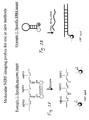
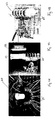
- FIGs. 1A and 1B show schematics of two probes designed to target a specific enzyme (1A) and a specific DNA sequence (1B). When the fluorochrome is released or spatially separated from its quencher, fluorescence can increase up to 1000 fold.
- a small molecule quencher e.g., DABCYL (a non-fluorescent chromophore that serves as a universal quencher for any fluorophore in a molecular beacon: 4-(4-dimethylaminophenylazo)-benzoic acid) or QSY-7) or by multiple fluorochromes (e.g., through energy resonance transfer).
- FIGs. 1A and 1B show schematics of two probes designed to target a specific enzyme (1A) and a specific DNA sequence (1B). When the fluorochrome is released or spatially separated from its quencher, fluorescence can increase up to 1000 fold.
- these probes can be used to extract molecular information from living organism.
- These activatable probes have four major advantages over other methods when single fluorochromes are attached to affinity molecules: (1) a single enzyme can cleave multiple fluorochromes, thus resulting in one form of signal amplification, (2) reduction of background "noise" by several orders of magnitude is possible, (3) very specific enzyme activities can potentially be interrogated, and (4) multiple probes can be arranged on delivery systems to simultaneously probe for a spectrum of enzymes.
- a panel of highly specific enzyme-sensitive molecular probes have been synthesized that target matrix metalloproteinase-2 (MMP-2), cathepsin B/H, cathepsin D, cathepsin K, PSA, and caspase-3), and which are capable of fluorescence activation at 600-900 nm.
- MMP-2 target matrix metalloproteinase-2
- cathepsin B/H cathepsin D
- cathepsin K cathepsin K
- PSA cathepsin K
- caspase-3 caspase-3
- Reporter fluorochromes Hundreds of optical probes have been developed for microscopy and photodynamic therapy. Of these, fluorescent probes (i.e., excitation at shorter wavelength and emission at longer wavelength) are ideally suited for studying biological phenomena, as has been done extensively in fluorescence microscopy. If fluorescent probes are to be used in living systems, the choice is generally limited to the near infrared spectrum (600-1000 nm) to maximize tissue penetration by minimizing absorption by physiologically abundant absorbers such as hemoglobin ( ⁇ 550 nm) or water (> 1200 nm). Ideally the fluorochromes are designed to emit at 800 ⁇ 50 nm.
- NIRF probes for in vivo use ideally should have the following properties: (1) narrow emission bandwidths, (2) high fluorescence efficiency (quantum yield), (3) biocompatibility, and (4) spectrally separated absorption and excitation.
- Target Substrates The release and or availability of individual fluorochromes is determined by interaction of a target substrate with its target.
- a target substrate can, for example, be a peptide sequence that is cleaved by enzymes (see Table 1 below), a phosphate group which is transferred by certain kinases, or a hybridizing DNA sequence recognizing a specific complementary DNA motif (see FIG. 1B ).
- Delivery Vehicle For a quenched probe to reach its intended target, it has to evade rapid clearance/elimination and overcome several structural barriers to delivery. These barriers include: (1) extravasation from vessels, (2) diffusion through tissue, and (3) cell membrane translocation in the case of intracellular enzymes (not required for secreted enzymes). These barriers to delivery are fairly well investigated, and delivery vehicles can be selected using standard techniques and information. Suitable vehicles to deliver fluorochromes and substrates to a target, e.g., a tumor, in the body can be selected from a group of polymers, including protected graft co-polymers ( Marecos et al., Bioconjug.
- PEG polyethylene glycol
- polaxamers polyethylene glycol
- Additional delivery vehicles include dendrimers, proteins, carbohydrates, lipid spheres (e.g., emulsions, liposomes, and lipid self-assemblies), nanoparticles, and other materials commonly used for parenteral drug delivery.
- enzyme activatable probes for use in the new methods can be prepared as follows (see, Weissleder et al., U.S. Patent No. 6,083,486 ; Weissleder et al., Nat. Biotechnol., 17:375-8, 1999 ).
- a protected graft copolymer (PGC) consisting of a poly-L-lysine (PL) backbone and methoxy poly-e-ethylene glycol (MPEG) side chains is first synthesized ( Bogdanov et al., J. Drug Targeting, 4:321-330, 1997 ).
- cathepsin D sensitive probes have been synthesized ( Tung et al., Cancer Res., 60: 4953-8, 2000 and Tung et al., Bioconj. Chem., 10:892-896, 1999 ). Briefly, PGC was reacted with large excess of iodoacetyl anhydride to convert all amino groups on the polylysine backbone into iodol groups.
- the cathepsin D specific peptide, GIC(Et)FFKK(Fitc)C was attached to the iodinated PGC through a thiol specific reaction.
- probes described above are specifically designed to become activated upon target interaction, e.g., target enzyme interaction.
- Alternative probes that can be used in the new detection methods include (1) probes that become deactivated (quenched) after target interaction, (2) probes that change their quantum yield upon target interaction, (3) probes that change their fluorescence lifetime after target interaction, (4) probes that change their fluorescence spectrum after target interaction, (5) wavelength shifting beacons ( Tyagi et al., Nat. Biotechnol., 18:1191-1196, 2000 ), (6) multicolor fluorescence probes ( Tyagi et al., Nat.
- probes that have high binding affinity to targets i.e., that remain within a target region while non-specific probes are cleared from the body.
- examples of the latter probes include receptor-targeted NIR fluorochromes ( Achilefu et al., Invest. Radiol., 35:479-485, 2000 ) or antibody-targeted NIR fluorochromes ( Ballou et al., Biotechnol. Prog., 13:649-658, 1997 ), (8) non-specific agents with compartmental distribution, (9) quantum dots, and/or (10) any fluorescent molecules with effects on fluorochromes.
- Another group of suitable fluorescent probes are long lifetime lanthanide metal-ligand probes that will allow the use of gated detection, and further increased sensitivity.
- the new systems can use a charge-coupled device (CCD) camera and lens system to obtain "tomographic measurements" from the periphery of a multipoint incident light array, such as a cylinder with numerous, spaced, light emitters, for three-dimensional optical scans. Improvements in NIR image quality are related to the number of sources and detectors used.
- CCD technology is that increasing the detector density does not require additions in the detection hardware, just additional optic fibers to create a bigger array.
- the tomographic methodology described herein is an improvement of the general category of tomography using diffracting sources (see, e.g., Kak and Slaney, "Principles of Computerized Tomographic Imaging,” IEEE Press, New York, 1988, pp. 208-218 ).
- the technique uses measurements of light at multiple projections to obtain information of the optical contrast inside turbid media such as tissue.
- diffraction tomography segments the volume under investigation into a number of discrete voxels, referred to as a "mesh.”
- the analysis is divided into two steps.
- the first step is the "forward problem," in which a diffusion equation is used to describe the photon propagation into an assumed medium, e.g., tissue, and is used to predict the field detected from this medium.
- the second step is the "inverse problem," in which the optical properties of each voxel of the assumed medium are updated to minimize the errors observed between the predicted and measured fields.
- the forward problem analytical and numerical solutions of the diffusion equation
- inverse problem direct inversion, ⁇ 2 - based fits, and algebraic reconstruction techniques.
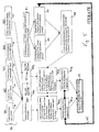
- a numerical solution of the forward problem is used to generate the prediction vectors for the fluorescence and intrinsic signal measurements (See also FIG. 5 ).
- Inversion is based on the relaxed algebraic reconstruction technique. Higher order solutions can be obtained if needed when a solution is fed back in the forward problem to produce more accurate forward propagation models, and this process can be repeated iteratively.
- the new FMT imaging systems use one or more laser sources to detect specific chromophores or fluorophores and the forward problem is calculated for the specific wavelength(s) used.
- Laser diodes can be used as light sources since they produce adequate power, are within FDA class I and class II limits, and are stable, wavelength-specific and economical. Light is directed to and from tissue using fiber guides, as this allows flexibility in the geometrical set-up. For optical coupling, the fibers have to be in contact with tissue. Alternatively, matching fluid is used to eliminate reflections due to air-silica-tissue index of refraction mismatch.
- the simplest is continuous wave (CW) imaging.
- This technique uses light of constant intensity and measures either (1) the signal due to a distribution of excited fluorophores or (2) the attenuation of light (due to tissue absorption and scattering) employing multiple source-detector pairs.
- the technique is technically relatively simple and usually offers the best signal-to-noise (SNR) characteristics.
- SNR signal-to-noise
- it is not best suited for imaging of intrinsic tissue contrast since it usually introduces significant cross-talk between the calculations and imaging of absorption and scattering coefficients.
- the background optical properties are known, the method is well-suited for imaging fluorophore concentration in the steady-state.
- IM intensity modulated
- the technique offers two pieces of information, i.e., intensity attenuation and phase shift per source-detector pair. Amplitude and phase are usually uncorrelated measurements and can more efficiently resolve the absorption and scattering coefficient of intrinsic contrast. In the fluorescence mode, the technique can image two sets of information, fluorophore concentration and fluorescence lifetime.
- the third approach uses short pulses of light injected into the tissue.
- the technique resolves the distribution of times that the detected photons travel into the medium for multiple source-detector pairs.
- the time-resolved method offers a CW component for direct comparison with the CW system, but also intensity attenuation and phase-shift measurements at multiple-frequencies (via the Fourier transform) that can image intrinsic absorption and scattering, and also fluorophore concentration and fluorescence lifetime.
- the bulk information is collected using economical, massively parallel CW measurements ( ⁇ 1000 channels) and highly specific information of absorption and scattering parameters are collected with a smaller array of time-domain source-detection channels ( ⁇ 50-100 channels).
- the time-domain information is used in three ways. The first is to independently quantify the average absorption and reduced scattering coefficient at the emission and excitation wavelength. The second is to implement time-domain measurements of intrinsic signal into the intrinsic reconstruction scheme by Fourier transforming the time-domain data, hence obtaining multiple-frequency readings.
- the third use of the time domain system is to implement time-domain measurements of fluorescent signal into the fluorescent reconstruction scheme by Fourier transforming the time-domain data, and obtain information of the fluorescence lifetime of the NIRF probe. Due to the equivalency of signals detected using pulsed light or intensity-modulated light at multiple frequencies via the Fourier transform, identical methods and systems can result when using intensity modulated light at multiple frequencies. A simplified approach is to use intensity modulated light at a few or a single frequency.
- the new imaging systems include an apparatus with various components used to generate digital signal data from analog fluorescence emitted from a patient or animal body, and a processor programmed with algorithms that can process the digital signal data into useful images that provide diagnostic and prognostic information.
- the systems can also obtain measurements of the incident light after it propagates through the tissue and obtain information on the intrinsic contrast of the body being imaged.
- Diffraction tomography differs from simple projection imaging in that it requires tissue transillumination at multiple projections. Therefore, the construction of an appropriate light guiding apparatus is fundamental to obtain molecular tomographic images using NIR light.
- the system features a multipoint incident illumination array and a multipoint detector array, both incorporated into a single cylinder, to be placed around the animal or patient body.
- a multipoint incident illumination array and a multipoint detector array both incorporated into a single cylinder, to be placed around the animal or patient body.
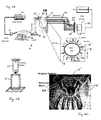
- FIG. 2A and FIG. 4 One such apparatus is shown in FIG. 2A and FIG. 4 .
- the two instruments can operate sequentially.
- System 10 includes a continuous wave (CW) laser source 12.
- the laser 12 uses constant intensity light. Two wavelengths obtained from two different lasers can be used for imaging the intrinsic contrast before the administration of the NIRF probe. For imaging the fluorochrome Cy 5.5, one wavelength is set to 673 nm (excitation wavelength) and the other to 694 nm (emission wavelength). Imaging at both wavelengths is necessary so that accurate forward models are created for the excitation field from the source to the fluorophore and for the emission field from the fluorophore to the detector. The other combination of wavelengths will target the fluorochrome ICG at 750 nm (excitation) and 800 nm (emission).
- the two wavelengths are time-shared since the measurements are not very demanding in terms of time efficiency and are coupled through an optical attenuator 14 to a 1 x 32 optical switch 16 (e.g., an optical switch from Dicon FiberOptics Irvine CA).
- the optical switch 16 directs light from laser 12 to any one of multiple (sixteen in this embodiment) source fibers 18. Alternatively, all fibers can be illuminated simultaneously, each at a different wavelength. The key is to be able to distinguish each point of illumination on the multipoint incident illumination array 20.
- the multipoint incident illumination array 20 is located within a resin cylinder 15 (also referred to herein as an "imaging chamber"), with several rings of multiple source fibers 18 connected around the cylinder.
- cylinder 15 has numerous holes drilled into it in a series of "rings” at different levels of the cylinder and perpendicular to the central axis. The holes can be equally spaced around the perimeter of the cylinder.
- the source fibers 18 pass through the holes in cylinder 15 and end flush with the inner wall.
- a multipoint detector array 21 is incorporated into the same cylinder 15, in the form of rings of detector fibers 22 interleaved (alternating) with the rings of the source fibers 18. Again, the cylinder has holes drilled for each detector fiber.
- Detector fibers 22 form the detector array 21 of cylinder 15, and, like the source fibers, end flush with the inner wall of the cylinder.
- three rings of twelve detection fibers each are interleaved with two rings of sixteen source fibers each, each ring at 3 mm from the next, thus covering a total cylinder height of 1.2 cm.
- Cylinder 15 (including multipoint incident illumination array 20 and multipoint detector array 21) can be filled with a liquid optical contact medium (e.g., Intralipid® or an emulsion of TiO 2 particles and appropriate amounts of an absorbing fluorophore or fluorochrome that simulate the optical properties of the tissue examined), which serves as the "coupling" fluid of diffuse photons from the surface of the animal body to the detection fibers.
- a liquid optical contact medium e.g., Intralipid® or an emulsion of TiO 2 particles and appropriate amounts of an absorbing fluorophore or fluorochrome that simulate the optical properties of the tissue examined
- the concentration of TiO 2 particles for the matching fluid and the resin cylinder will be such as to induce scattering properties comparable with the average reduced scattering coefficient of mice.
- Fluorescent light collected by multipoint detector array 21 is fed through detector fibers 22 to a two-dimensional emitted fluorescent light array 24.
- the two-dimensional array 21 transmits the analog fluorescent light emitted from the body through a long-pass filter 25 (depending on the fluorochrome used) and to a CCD camera 26.
- the long-pass filter 25 will be selected for the appropriate cut-off wavelength, similar as done for surface reflectance type on imaging systems ( Mahmood, Radiology, 213:866-870, 1999 ). To image intrinsic contrast the filter is removed.
- the CCD camera 26 is mounted on a breadboard, and a lens 27, or a system of macro lenses, images the two-dimensional emitted fluorescent light array onto the CCD camera.
- Optimum light attenuation will be set by the optical attenuator 14 so that measurements will not saturate the CCD camera.
- the useful dynamic range is approximately three to four orders of magnitude. This is also the dynamic range expected for measurements of diffuse light in small animals with body diameters of about 2-3 cm.
- the dynamic range expected for human patients may differ depending on the target organ. For example, for human breast imaging, at an approximate diameter of 8 cm, the dynamic range required is about 6-8 orders of magnitude.
- This dynamic range can be covered using CCD technology by rapidly acquiring multiple frames. With current CCD technology used at 10 frames per second, the dynamic range can be 6 orders of magnitude in one second of acquisition.
- higher dynamic range may be achieved with longer acquisition times or more time-efficiency by using programmable attenuators that selectively attenuate the higher signals with a known level of attenuation.
- a positional device 23 can be used for optimum placement of the animal in cylinder 15 as shown in FIG. 2B .
- the positional device in this embodiment is simply a cylinder that fits snuggly within cylinder 15.
- Three positional devices 23 (cylindrical inserts) have been constructed.
- the first insert is constructed of Lexan® (polycarbonate) or Plexiglas®, and the second is constructed of white Delrin®, Polypropylene, or Kel-F®. Both of these inserts have an outer diameter that exactly fits the inner diameter of cylinder 20, 21, and are 1mm in thickness.
- the third insert is constructed out of Mylar® film and Kel-F® film to produce an insert with a wall thickness of 0.1 mm diameter.
- FIG. 2C A detailed view of cylinder 15 (the imaging chamber), including both the multipoint detector array 21 and the multipoint incident illumination array 20, is shown in FIG. 2C .
- the source fibers 18 and detector fibers 22 are arranged so that measurements are obtained along the entire cylinder to allow for three-dimensional reconstructions. Source fibers 18 are interleaved between the detector fibers.
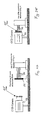
- FIGs. 2D and 2E illustrate two alternative fiber-coupling systems.
- FIG. 2D shows the system used in FIG. 2A , in that a separate two-dimensional emitted fluorescent light array 24 is used to collect the signals of all detector fibers 22 in one plane, which is imaged by CCD camera 26 through filter 25.
- FIG. 2E shows a simpler embodiment in which the detector fibers 22 are directly connected to filter 25, i.e., filter 25 serves as the two-dimensional array 24.
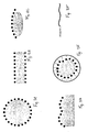
- FIG. 3A illustrates a top view of the cylindrical array described above.
- FIG. 3B shows a planar array used for reflectance and/or transmittance mode operation.
- the array is a portion of a cylinder, e.g., in the form of a curve with a set radius as shown in FIG. 3C .
- FIG. 3C shows a planar array used for reflectance and/or transmittance mode operation.
- FIG. 3D shows a schematic of a molded array, in which the ends of the light source fibers are arranged on a rigid substrate that conforms to a specific shape of a body, or are arranged on a substrate of bendable, elastic material, such as a plastic, rubber, or cloth that can secure the light emitting optic fibers, and that can be molded to conform to a body shape.
- FIG. 3E illustrates a belt-like, uneven array, in which the ends of the source fibers are arranged in a flexible belt that can be fastened around a patient or the limb of a patient as required. The exact positions of the light emitting points within this array can be determined and corrected for by concomitant CT, US, or MR imaging.
- the ends of the light source fibers are provided in a catheter-like device as shown in FIG. 3F .
- the ends of the detector fibers 22 can be interleaved with the ends of the source fibers 18 as in the cylinder 15 shown in FIG. 2A .
- the detector array can be separate and distinct from the incident illumination array, as long as the ends of the detector fibers are spaced in a specified geometry with respect to the ends of the source fibers.
- the preferred mode of use is with a separate detector array that positions the ends of the detector fibers on the outside of the body while the incident light array is positioned inside the body, e.g., to image the prostate gland, lungs, vasculature, or gastrointestinal tract.
- the apparatus 10 of FIG. 2A is used with a processor 11, e.g., located in a PC, as described in further detail below.
- a processor 11 generally includes an input/control device 60, a memory 62, and an output device 64.
- the processor 11 can be an electronic circuit comprising one or more components.
- the processor can be implemented in digital circuitry, analog circuitry, or both, it can be implemented in software, or may be an integrated state machine, or a hybrid thereof.
- Input/control device 60 can be a keyboard or other conventional device, and the output device 64 can be a cathode ray tube (CRT), other video display, printer, or other image display system.
- Memory 62 can be electronic (e.g., solid state), magnetic, or optical.
- the memory can be stored on an optical disk (e.g., a CD), an electromagnetic hard or floppy disk, or a combination thereof.
- a highly efficient photon collection apparatus of FIG. 2A can be built using the same or similar components as discussed above, but with the exception that dedicated detector fibers 22 are directly coupled to the CCD (as shown in FIG. 2E ), versus the lens system shown in FIGs. 2A and 2D . Overall, this system design should provide at least 300% improved photon counting efficiency. Higher efficiency CCD chips will further improve photon detection.
- the apparatus of FIG 2A can accommodate more source-detector pairs (for example 64 x 100) either by a lens-imaging system ( FIGs. 2A and 2D ) or by direct coupling (as shown in FIG. 2E ).
- the latter system could require a larger dimension chip CCD camera to accommodate the larger detector set.
- baseline measurements can be obtained from the tissue at the excitation wavelength and at the emission wavelength without using the filter. Fluorescence measurements can be performed at the emission wavelength after inserting the appropriate cut-off filter.
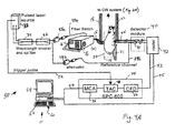
- FIG. 4A An add-on system that will significantly enhance the tomographic accuracy is shown in FIG. 4A .
- This is a time-resolved FMT imaging system 30.
- a 16 x 16 channel array is implemented together with CW measurements to yield superior reconstructions.
- the CW and TR system can be used independently but a benefit is achieved when the measurements obtained from both systems are combined in the same reconstruction scheme.
- system 30 includes a pulsed laser source 32, a wavelength coupler 34 and a wavelength splitter 36.
- Two sets of two pulsed laser diodes (pulse with ⁇ 70 picosecond, average power ⁇ 150 ⁇ W) are employed at the same wavelengths as the proposed CW system of FIG. 2A .
- the wavelengths are used time-multiplexed with 10 nm delays; they are detected simultaneously by the 16-channel single photon counting time-resolved system 44 (e.g., a SPC-600® from Pico-Quant, Berlin, Germany).
- the time-resolved system can share the same source fibers 18' as the CW system 18 (by connecting both CW and TR light sources to the optical switch) or use separate, dedicated source fibers.
- the time-resolved (TR) detection fibers 22' will be interlaced with the CW detector fibers 22.
- the TR acquisition will be obtained at different times than the CW acquisition to avoid cross-talk between the CW and TR systems.
- the relatively small source-detector array 18', 22' of the TR system (which can also be incorporated into cylinder 15) is capable of producing useful diffuse images.
- the two main contributions of the TR data will be (1) their simultaneous implementation is the inversions of Eq. 1 to obtain multi-frequency information in addition with the CW data offering a stand-alone CW-TR tomographer, but also (2) their use with the concurrent magnetic resonance (MR) information to obtain measurements of fluorescence concentration and lifetime from the tumor lesions as identified on the MR images.
- MR magnetic resonance
- the pulsed laser source 32 produces laser light that is coupled by wavelength coupler 34 and then split by splitter 36.
- the splitter directs ⁇ 99% of the laser light along path 39a into the optical switch 16 and 1% of the light along path 39b into the detector module 40 via the corresponding attenuators 38a and 38b.
- the light traveling along path 39b from attenuator 38b provides a "reference signal" that is used to monitor the system's temporal drifts and signal stability.
- the 99% part of the laser light on path 39a that is directed to the optical switch 16 is switched in the same manner as in the CW system to selected sixteen (or more, if needed) CW source fibers 18. There is no need to use two different switches and source fibers.
- Fibers 18 can be (but need not be) physically identical to fibers 18' and the only differentiation is made for ease of illustration to indicate their operation passing CW or TR signals.
- a 2-to-1 optical switch 16' e.g., provided within the Dicon switch 16, can select between the CW or TR source.
- an independent TR detector fiber array (sixteen fibers) is required to direct the collected photons at the time resolved detection system 44.
- Cylinder 15 is the same as in FIG. 2A . Fluorescent or intrinsic light emitted from the body is passed to the TR system as in FIG. 2A and to detector module 40. Fibers 22 indicate the detector fibers of the CW system shown on FIG 2A .
- Detector module 40 includes photomutiplier tubes (PMT) 41 that detect photons and convert single photons to electrical analog pulses. These analog pulses pass to router 42, which directs the pulses via path 43 to the SPC-600 board 44. Here the pulses are converted to digital values that indicate the time of arrival (TOA) of each coming pulse relative to the trigger pulse on path 52 coming from laser 32. Each collected pulse generates in router 42 a digital address, which uniquely marks the detection channel from which this photon was detected. This digital address is directed to the computer memory 62 via digital cable 45 and is used to store the TOA in the appropriate memory bin allocated for each individual channel. For the sixteen channels used in this embodiment, there are sixteen separate digital addresses corresponding to sixteen separate memory bins.
- PMT photomutiplier tubes
- constant fraction discriminator CFD 50 rejects pulses that have a very small amplitude and are probably due to photo-electronic noise
- the Time-to-Amplitude Converter (TAC) converts the time of pulse arrival to an analog amplitude value
- the Multi-Channel Analyzer (MCA) converts this analog amplitude to a digital value at high speed.
- the output 47 of system 44 is a digital value stored in the computer memory bin that corresponds to the address carried on cable 45.
- Time-resolved measurements can be used independently to obtain average background properties of the medium measured, an important input parameter for absorption, scattering, and fluorescence reconstructions.
- the combination of TR and CW measurements will produce more accurate forward problems for the intrinsic contrast and fluorescence reconstructions.
- the simultaneous use of CW and TR data will enhance the overall image quality and fidelity.
- Another alternative would be to use the time-resolved data to produce low-resolution images of background intrinsic contrast and use this information to create more accurate forward problems for the CW reconstructions for each animal.
- the CW and especially the TR information can further be combined with MR imaging data to produce accurate quantitative measures of fluorophore concentration and fluorescence lifetime measurements.
- Time-resolved or intensity-modulated methods would significantly open the spectrum to differentiate the fluorescence decay of existing and novel fluorochromes distributed in tissue.
- the cyanine fluorochromes that are described above typically have decay times ranging from 1 to 20 ns. While this timescale is useful for many biophysical measurements, there are numerous instances where longer decay times are desirable. For instance, one may wish to measure rotational motions of large proteins or membrane-bound proteins.
- One attractive feature is to combine molecular maps derived from FMT imaging with anatomical tomographic images, e.g., those derived from magnetic resonance (MR), X-ray computed tomography (CT), ultrasound (US) or even single photon emission tomography (SPECT) or positron emission tomography (PET) imaging.
- MR magnetic resonance
- CT X-ray computed tomography
- US ultrasound
- SPECT single photon emission tomography
- PET positron emission tomography
- DOT imaging absorption only
- MR imaging Ntziachristos et al., P.N.A.S., USA, 97:2767-72, 1999
- one of the examples in this application teaches how to combine FMT imaging with MRI.
- This combination with MRI will enable: (1) the validation of FMT imaging in vivo by direct comparison of the MR and optically acquired images, (2) a direct comparison of cancer appearance and detection limits based on the anatomical images obtained by T2-weighed MR images, the Gd-enhancement pattern, and molecular activity as resolved with optical imaging, and (3) the implementation of MR structural and functional information as a priori information in the optical inversion scheme to obtain highly accurate measures of localized fluorophore concentration and lifetime.
- the combination of MRI and FMT also improves quantitation accuracy of fluorophore concentration and lifetime. Overall, molecular probing will improve the detection accuracy and introduce the ability of molecular target assessment.
- non-magnetic fiber bundles can be used to transport excitation and emission light to and from exciter/detection systems to the patient.
- available commercial or custom-built MRI coils available in any MR facility can be used.
- the MR coils can be coupled to one of the geometries described in FIGs. 3A-3F depending on the application.
- MR or CT imaging itself can be used. Knowledge of the spatial location of source fiber ends and detector fiber ends on uneven surfaces improves optical reconstructions.
- the skin-coupled fibers as shown in, e.g., FIG.
- the arrays can be detected by imaging if the arrays are constructed of materials that are uniquely detectable, e.g., materials that include microreference phantoms filled with magnetic/x-ray absorbing compounds, certain chemicals, or plastics.
- materials that are uniquely detectable e.g., materials that include microreference phantoms filled with magnetic/x-ray absorbing compounds, certain chemicals, or plastics.
- small reference capillaries filled with water and CuSO 4 can be attached to the cylinder to appear as bright spots on the MR images.
- FIGs. 4C and 4D are representations of a magnetic resonance (MR) coil 65 used for co-registration purposes.
- Coil 65 is specially built to accommodate the animal insert 23 shown in FIG. 2B .
- Two implementations are considered.
- insert 23 containing the animal is removed from the imaging chamber 15 and positioned within MR coil 65.
- One or more specially designed glass capillaries 66 (1 mm glass tubes filled with water and copper sulfate) are attached to insert 23 and enable the MR and FMT images to be co-registered.
- Such a fiducial marker is visible as a bright circular spot on the left side of the MR image in FIG. 8A (discussed below).
- FIG. 4D shows a mouse positioned within positioning insert 23, within MRI coil 65.
- the second embodiment has the coil built directly around imaging chamber 15 of FIG. 2A so that concurrent MR and FMT examinations can be performed.
- the M3 measurement can be theoretically constructed or derived by means of the M2 measurement and therefore its acquisition be eliminated. Although subsets of the collected data can be used depending on the requirements of the application, the highest accuracy is obtained when the M1, M2, M4 sets are utilized for fluorochrome reconstructions and the M1, M2, M4, M5 sets are used for deriving optical maps.
- the fluorescence measurement M1 is obtained. This is a measurement where the source is scanned at multiple positions, and the detector acquires the light emitted from the tissue with the band-pass filter on, so that only the emission wavelength (fluorescence) is collected.
- the second measurement, M2 is made as in step 71, but without the band-pass filter to acquire the intrinsic signal from the tissue at each wavelength. If the fluorescence signal is very small compared to the intrinsic signal no filter is required.
- step 73 measurement M3 is made to acquire the amount of intrinsic light that passes through the fluorescence filter (high-pass filter) used in step 71.
- the tissue to be investigated is removed from the cylinder, and a measurement is made from the matching fluid with the fluorescence filter (band-pass filter) on. This measurement is also used to acquire the contribution of ambient light and other photonic and electronic noise on a per source basis.
- the factor q1(r) can be determined experimentally by flat field measurements or can be calculated based of filter specifications.
- Constant ct represents an image of the background dark noise measurement of the CCD camera.
- step 74 measurement M4 is obtained with all sources turned off to acquire only the ambient (background) light and CCD noise.
- measurement M5 is obtained without a filter and without tissue at the excitation and the emission wavelength using appropriate laser diodes. This measurement acquires the background signal.
- each of measurements M1, M2, M3, and M5 is a series of Ns images (where Ns is the number of sources used). M4 is a single image of background noise.
- each of M1, M2, M3, and M5 is a set Ns x Nd, where Nd is the number of detectors. For multispectral imaging the number of measurements acquired is multiplied by the corresponding number of wavelengths employed.
- the measurements M1-M5 are functions of the frequency. Therefore, CW and TR data (after Fourier transformation) are handled in exactly the same way.
- the rationale for this construction is that these composite measurement vectors are independent of instrumental gain variation, such as differences in the attenuation between different source or detector fibers and inhomogeneities within the CCD chip. Furthermore, these vectors subtract from the actual measurements systematic errors such as background noise (M4) or high-pass filter imperfectness (M3).
- M4 background noise
- M3 high-pass filter imperfectness
- measurement M5 could be substituted by measurement M2 at time 0, preferably before the NIRF probe has been administered to the animal. Therefore the fluorochrome absorption can be accurately monitored as a difference signal from intrinsic tissue absorption.
- CM composite measurements
- P forward predictor
- the P for fluorescence is constructed based on a modified Born prediction of the forward problem ( Ntziachristos V, Weissleder R, Opt. Lett., 26(12): 893-895, 2001 ).
- the medium is assumed to contain a weakly absorbing distribution of fluorophores.
- the fluorophores are excited by this photon distribution and act as a secondary point source of fluorescent light.
- the fluorophores as two-level quantum systems and saturation effects are ignored because of the small concentration of NIRF probes that are administered.
- ⁇ fl r ⁇ d ⁇ r ⁇ s ⁇ V ⁇ g fl ⁇ r ⁇ - r ⁇ d ⁇ ⁇ cN t r ⁇ 1 - i ⁇ ⁇ ⁇ 0 r ⁇ ⁇ r ⁇ s ⁇ d ⁇ r ⁇
- ⁇ fl ( r d , r s ) is the detected fluorescence fluence at position r d for a source at position r s
- ⁇ 0 ( r , r s ) is the established photon fluence in the homogeneous medium due to a source at position
- g fl ( r - r d ) is a function that describes the propagation of photons in the diffuse medium at the emission wavelength.
- the forward predictor P' is determined (in step 88) using the Rytov expansion in the frequency domain, as described, e.g., in O'Leary et al., Opt. Lett. 20:426-428, 1995 ; and Ntziachristos et al., Proc. Natl. Acad. Sci., USA, 97:2767-72 2000 .
- ⁇ 0 ( r , r s ) is the incident field from the source at position r s to position r
- o ( r ) is the vector of the unknown absorption and diffusion coefficients changes relative to the assumed homogeneous background medium.
- the functions g fl and ⁇ 0 are calculated by simulating photon propagation at the emission (step 82) and excitation (step 84) wavelengths for the specific imaging chamber geometry and diffusion theory. This can be achieved either analytically or numerically. To perform these simulations, knowledge of the tissue average optical properties in the wavelengths of interest are required. The optical properties can be obtained by fitting all the intrinsic contrast TR measurements to the diffusion model for the appropriate geometry. Analytically, standard methods can be applied (adapted for the cylindrical geometry) as described in Li et al., Appl. Opt., 36:2260-2272 (1997 ).
- U is the vector of unknown non-quenched (activated) fluorochrome concentration
- O the vector of unknown absorption and diffusion distributions.
- the absorption distribution can be converted to flurochrome concentration via the Beer-Lambert Law.
- the matrices P, P' are described in the previous section.
- steps 92a and 92b the functions F(U) and F'(O) are minimized to obtain the distribution and magnitude of U and O, respectively.
- the minimization is obtained using algebraic reconstruction techniques although any other minimization method can me used to find the solution of the constructed functions.
- the first step of the iterative process 95 assumes a homogeneous background with the average optical properties of the medium of investigation. Subsequent steps use images U and O as background maps in the creation of matrices P, P'. When iteration is used, the creation of P, P' using numerical solutions of the diffusion equation is necessary. Iteration is also necessary when the background distribution of the fluorochrome is comparable to the contrast obtained from localized areas of high accumulation such as the tumor. Iteration is typically stopped when each iteration step does not significantly change the calculated result.
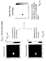
- the new systems and methods enable the quantitative, three-dimensional calculation of molecular and molecular-activation maps.
- the resolved image U contains the concentration of fluorescing or activated fluorochrome, whereas the absorption image contained in O is a quantitative representation of the total fluorochrome concentration (quenched and de-quenched).
- a molecular map is a representation of an endogenous process or molecule.
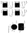
- FIG. 6A is an image of an absorption map, showing the concentration of a molecular probe sensitive to degradation by trypsin.
- the bright spot in FIG. 6A is a representation of the total amount of the probe, both the quenched and the unquenched fractions.
- FIG. 6B is the corresponding fluorescence map, which measures only the fraction of de-quenched (i.e., enzyme activated) trypsin sensitive probe.
- FIG. 6C provides the AR image, or "molecular map,” displaying the "fluorescence activation” as an image where the bright spot is directly proportional to the amount of added trypsin enzyme used in this experiment.
- phantom experiments were performed to verify the three-dimensional position and accuracy of measurements.
- the experimental set-up is illustrated in top view in FIG. 7A .
- a phantom 100 containing 3 capillary tubes (1 mm internal diameter) 103 was constructed using a triangular geometry and inserted into the optical chamber (15 in FIG. 2A ) containing a turbid medium 102 (0.5% Intralipid® in water).
- the capillaries 103 were separated 8 and 11 mm from each other as shown in FIG. 7A , and were coated with a black fluorochrome to maximize absorption.
- the capillaries were imaged three dimensionally.
- FIG. 7B depicts the reconstructed image 110 at a plane perpendicular to the longitudinal axis of the imaging chamber 15, at about the middle of the three-dimensional volume imaged.
- the high contrast allowed for high-resolution imaging of the three capillaries with high positional precision.
- the reconstruction mesh used was 0.8 x 0.8 x 2 mm 3 .
- the reconstruction used 24 sources x 36 detectors.
- FIGs. 8A and 8B In another experiment, quantitative, spatially localized information on fluorescence activation was obtained as a function of time.
- a 3mm tube 123 was immersed in a tissue-like fluid (Intralipid®) to form phantom 102.
- the tube contained 1.5 ⁇ M of a Cy5.5 probe, which was activated by the addition of the enzyme trypsin into the tube at time 0. Only a single plane was imaged in this experiment by sequentially illuminating each of twelve light emitting points in the direction of curved arrow 125.
- FIG. 8B illustrates the phantom in a three-quarter view.
- FIGs. 8C to 8F illustrate a series of axially reconstructed frames obtained at different time points.
- the frames show the probe activation as a function of time. For example, as shown in FIG. 8C , at 20 minutes after trypsin was added to the capillary, only ⁇ 20% of the probe had been activated. However, as shown in FIG. 8F , at 200 minutes after the enzyme was added, ⁇ 75% of the probe had been activated.
- Each frame was acquired by sequentially directing light in each one of twelve source fibers located on the same plane along the cylinder. For each source, the CCD acquired light from the detector fibers for 5 seconds. The total acquisition time per frame was therefore 1 minute (12 sources x 5 seconds each).
- FIGs. 9A-(C ) The tumors were cathepsin B rich HT1080 fibrosarcoma, which had been implanted into the mammary fat pad 7-10 days prior to the experiment.
- the animals received an IV injection of a cathepsin B sensitive imaging probe ( Weissleder et al., Nat. Biotechnol., 17:375-378, 1999 ) at 24 hours prior to the imaging experiments.
- the animals were anaesthetized with an intraperitoneal injection of 90 mg/kg ketamine and 9 mg/kg xylazine and were placed into the insert 23 shown in FIG. 2B .
- the insert and animal were placed into the imaging chamber 15 and measurements M1, M2, M3, and M4 were obtained.
- Fiducials as described herein
- the insert was subsequently placed in the MR coil and a set of axial T2-weighted imaged were obtained.
- the role of the fiducials was to identify on the MR images the position of selected source and detector fibers for later co-registration of the images.
- the fiducial (a glass capillary tube arranged longitudinally along the outside cylinder wall) shown on the slices of FIGs. 9A, 10A, and 11A as a bright spot on the left side of the image, for example, indicates the position of detectors 1, 13, and 25 on the corresponding slices.
- FIG. 9A The results show an MR image ( FIG. 9A ), a cathepsin B molecular map (FMT)( FIG. 9B ), and one of the MR slices fused with the FMT image to produce a combined MR/molecular map ( FIG. 9C ).
- the tumor demonstrates strong molecular activity of cathepsin B (fluorescence activation), corroborated by immunohistochemsitry and Western blotting.
- the co-registration of the fluorescent activation and T2 image are shown on the fused image in FIG. 9C .
- the remaining two rows of images are slices that show cathepsin B absence and/or presence in other tissues. Specifically, FIGs.
- FIGs. 10A and 10B show an MR image and FMT image at heart level, respectively. As expected, there is no cathepsin B activity in the lung and heart, and thus nothing lights up on the FMT image in FIG. 10B.
- FIGs. 11A and B show an MR image and FMT image at kidney level, respectively. The fluorochrome appearing in the kidney is likely excreted excess, and does not reflect cathespin activity.
- Example 3 To demonstrate the use of producing molecular maps we have used the set-up of Example 3, but acquired the full array of M1 through M5 measurements in CW mode. The optical properties of Intralipid® were independently measured with a time-resolved system. Then a fluorescence map ( FIG. 6B ) collected 50 minutes after trypsin activation and an absorption map ( FIG. 6A ) were constructed according to the algorithm described in the flowchart in FIG. 5 . The molecular map (AR image) calculated according to step 93 is shown in FIG. 6C and demonstrates 40% activation of the enzyme sensitive probe 50 minutes after activation.
- the probes are specific for cathepsin D, cathepsin K, the enzymatically active form of prostate specific antigen (PSA), and matrix metalloprotease-2, among other enzymes.
- the specificity of these probes was shown by incubation with purified or recombinant human enzymes and by measurement of fluorescence activation in a fluorometer.
- the NIR fluorophore Cy5.5 was used as a quenched reporter in all of these probes. Any of these probes can be used in animals and human patients as described herein to measure enzyme activity within deep tissues (both normal and diseased tissues).
- MMP-2 activity can be measured in tumors before and after treatment with an MMP-2 inhibitor (e.g., Prinomastat®, Agouron Pharmaceuticals, Inc., San Diego, CA).
- MMP-2 inhibitor e.g., Prinomastat®, Agouron Pharmaceuticals, Inc., San Diego, CA.
- Such measurements of molecular target assessment are useful for rapid drug efficacy screening in vivo in animal models.
- screening methods can be used to assess the efficacy of a particular therapy in a specific patient.
- the new FMT methods are expected to have broad clinical implications.
- One use is for early detection of disease at a stage when molecular abnormalities are present, but have not yet led to phenotypic abnormalities (e.g., mutations in cancers which have not yet produced a tumor mass).
- Another use is for molecular target assessment in diseased tissues (1) to determine if a given target is present in a patient (e.g., level of expression of a protease), (2) to determine whether an experimental drug has an effect on its intended molecular target in vivo, (3) to individualize and tailor treatments for a given patient, and (4) to optimize the dose of a given molecular drug for a given patient.
- the new FMT imaging methods are an adjunct to testing drug efficacy.
- Such measurements would also be of value in a clinical setting to determine the effects of enzyme inhibitor drugs, receptor blockers, and other molecular drugs.
- the methods could be used to monitor a wide variety of disease including cancer, cardiovascular disease, AIDS, infection, immunologic diseases, inflammation, dermatological and ophthalmic diseases, neurodegenerative disease and others.
- the new FMT methods can be performed with the concomitant use of multiple molecular probes (each with their own, specific excitation and emission wavelengths) to report multiple molecular abnormalities during the same FMT imaging acquisition.
- the described system can be adapted by adding one or more new laser sources to excite the additional fluorescent molecular probes. Imaging signals are collected through appropriate filter systems, making sure that there is not spectral overlap among the different channels. Image reconstruction, algorithms, and displays are similar to those for single wavelength imaging described herein.
- the TR system described herein can be modified by using one or more frequency domain sources, preferably at multiple frequencies.
- the theoretical formulation is written in the frequency domain so that the use of frequency technology is directly applied to the existing algorithms.
- the rationale behind using frequency domain technology is similar to TR technology in that it yields multi-frequency information that can differentiate absorption and scattering in intrinsic contrast mode and fluorophore concentration and life-time in fluorescence mode. If frequency technology is used, the instrument in FIG. 4A is substituted by sources modulated at one or several frequencies and detection channels that are responsible for signal demodulation, such as lock-in amplifiers or preferably quadrature demodulators, similar to the ones used for the detection of MR signals.
- the implementation of the composite measurements described above can be applied in several ways to obtain fluorescent and intrinsic contrast, and to construct the AR images.
- a general scheme of an animal injected with a NIRF molecular probe is considered in Eqs. 4 and 5, one can obtain measurements from an animal before injection of the NIRF probe and then obtain differential measurements of absorption and fluorescent contrast after NIRF probe injection.
- This technique has important applications in monitoring the kinetics of uptake and activation (as also demonstrated in Example 2).
- This approach also yields the most accurate results since differential measurements allow for the reconstruction of the fluorochrome/chromophore absorption independently of background absorption (since only the absorption change can be reconstructed). Therefore, more accurate AR maps can be produced as a function of time.
- An alternative implementation of composite measurements than the one used in Example 9 is to employ four or more wavelengths for each measurement set.
- N tissue chromophores N or more of these wavelengths are selected at a spectral region where the NIRF probe does not absorb. Therefore, true "intrinsic" contrast is obtained, i.e., contrast that is due only to the natural tissue chromophore concentrations.
- Using the spectral information of these chromophores one can calculate their absorption at the emission and excitation wavelengths of the NIRF probe. The other two wavelengths are used to construct absorption images at the excitation and emission wavelengths. Those latter images reconstruct absorption due to both the natural tissue chromophore concentration and the fluorochrome distribution. By subtracting the images obtained at the excitation or emission wavelength from the absorption images calculated only for the tissue natural chromophores, one can obtain the true fluorochrome/chromophore concentration.
- breast cancer detection can be achieved with a circular/cylindrical multipoint incident illumination array or with a compression/planar array.
- Brain measurements can be made with an elastic band of optical fibers attached to the skull or a planar/reflectance geometry could be applied. See FIGs. 3A-F for various arrays.
- the described FMT imaging methods can be conducted sequentially or simultaneously with MR or CT measurements, because the optical technology is compatible with other radiological modalities.
- CW measurements would be useful for the economical collection of large numbers of measurements.
- IM or TR as described above
- a clinical system can be built entirely based on CW technology.
- frequency-domain or time-domain technologies become cheaper, the whole system can be based only on frequency-domain or time-domain technologies.
- a subcategory of the general reconstruction scheme of molecular activation described is the use of simple transillumination of tissue for the detection of molecular events. This is a relaxation of the tomographic imaging to simple projection imaging, similar, but not same as the one described previously for reflectance imaging (Weissleder et al., U.S. Patent No. 6,083,486 ). Transillumination allows for measurements of absorbers of fluorochromes through the whole tissue, therefore it achieves penetration of several centimeters, in contrast to reflectance imaging, which can penetrate only for a few centimeters at the most. Transillumination of molecular events cannot resolve or quantify molecular activity in three dimensions, but can still be used to qualitatively monitor relative changes of molecular activation.
- the new systems and methods can be used to image endogenous fluorescence in an animal.
- a gene encoding a fluorescent protein such as green fluorescent protein or fluorescein
- a gene of interest can be included adjacent to a gene of interest that is to be expressed in an animal or human patient using standard gene therapy techniques.
- the expression of the gene of interest can be determined indirectly by imaging the fluorescent protein. If this protein is expressed, then the gene of interest has also been expressed.
Landscapes
- Health & Medical Sciences (AREA)
- Life Sciences & Earth Sciences (AREA)
- Physics & Mathematics (AREA)
- General Health & Medical Sciences (AREA)
- Chemical & Material Sciences (AREA)
- Immunology (AREA)
- Pathology (AREA)
- Nuclear Medicine, Radiotherapy & Molecular Imaging (AREA)
- Animal Behavior & Ethology (AREA)
- Public Health (AREA)
- Analytical Chemistry (AREA)
- General Physics & Mathematics (AREA)
- Optics & Photonics (AREA)
- Biochemistry (AREA)
- Radiology & Medical Imaging (AREA)
- Veterinary Medicine (AREA)
- Biophysics (AREA)
- Medical Informatics (AREA)
- Epidemiology (AREA)
- Medicinal Chemistry (AREA)
- Engineering & Computer Science (AREA)
- Biomedical Technology (AREA)
- Heart & Thoracic Surgery (AREA)
- Chemical Kinetics & Catalysis (AREA)
- Molecular Biology (AREA)
- Surgery (AREA)
- Investigating, Analyzing Materials By Fluorescence Or Luminescence (AREA)
- Compounds Of Unknown Constitution (AREA)
- Measurement Of The Respiration, Hearing Ability, Form, And Blood Characteristics Of Living Organisms (AREA)
- Investigating Or Analysing Materials By Optical Means (AREA)
- Luminescent Compositions (AREA)
- Polysaccharides And Polysaccharide Derivatives (AREA)
Priority Applications (2)
| Application Number | Priority Date | Filing Date | Title |
|---|---|---|---|
| EP08103270A EP1987764B1 (en) | 2000-11-27 | 2001-11-27 | Fluorescence-mediated molecular tomography |
| EP10179910.4A EP2319399B1 (en) | 2000-11-27 | 2001-11-27 | Fluorescence-mediated molecular tomography |
Applications Claiming Priority (3)
| Application Number | Priority Date | Filing Date | Title |
|---|---|---|---|
| US723033 | 2000-11-27 | ||
| US09/723,033 US6615063B1 (en) | 2000-11-27 | 2000-11-27 | Fluorescence-mediated molecular tomography |
| PCT/US2001/044764 WO2002041760A2 (en) | 2000-11-27 | 2001-11-27 | Fluorescence-mediated molecular tomography |
Related Child Applications (2)
| Application Number | Title | Priority Date | Filing Date |
|---|---|---|---|
| EP08103270A Division EP1987764B1 (en) | 2000-11-27 | 2001-11-27 | Fluorescence-mediated molecular tomography |
| EP10179910.4A Division EP2319399B1 (en) | 2000-11-27 | 2001-11-27 | Fluorescence-mediated molecular tomography |
Publications (3)
| Publication Number | Publication Date |
|---|---|
| EP1349490A2 EP1349490A2 (en) | 2003-10-08 |
| EP1349490A4 EP1349490A4 (en) | 2005-09-28 |
| EP1349490B1 true EP1349490B1 (en) | 2009-01-14 |
Family
ID=24904527
Family Applications (3)
| Application Number | Title | Priority Date | Filing Date |
|---|---|---|---|
| EP01989794A Revoked EP1349490B1 (en) | 2000-11-27 | 2001-11-27 | Fluorescence-mediated molecular tomography |
| EP08103270A Revoked EP1987764B1 (en) | 2000-11-27 | 2001-11-27 | Fluorescence-mediated molecular tomography |
| EP10179910.4A Expired - Lifetime EP2319399B1 (en) | 2000-11-27 | 2001-11-27 | Fluorescence-mediated molecular tomography |
Family Applications After (2)
| Application Number | Title | Priority Date | Filing Date |
|---|---|---|---|
| EP08103270A Revoked EP1987764B1 (en) | 2000-11-27 | 2001-11-27 | Fluorescence-mediated molecular tomography |
| EP10179910.4A Expired - Lifetime EP2319399B1 (en) | 2000-11-27 | 2001-11-27 | Fluorescence-mediated molecular tomography |
Country Status (8)
Families Citing this family (222)
| Publication number | Priority date | Publication date | Assignee | Title |
|---|---|---|---|---|
| US7328059B2 (en) | 1996-08-23 | 2008-02-05 | The Texas A & M University System | Imaging of light scattering tissues with fluorescent contrast agents |
| US7865230B1 (en) | 1997-02-07 | 2011-01-04 | Texas A&M University System | Method and system for detecting sentinel lymph nodes |
| US6592847B1 (en) * | 1998-05-14 | 2003-07-15 | The General Hospital Corporation | Intramolecularly-quenched near infrared flourescent probes |
| US7107116B2 (en) * | 1999-03-29 | 2006-09-12 | Genex Technologies, Inc. | Diffuse optical tomography system and method of use |
| US7054002B1 (en) | 1999-10-08 | 2006-05-30 | The Texas A&M University System | Characterization of luminescence in a scattering medium |
| US6614452B1 (en) * | 1999-11-15 | 2003-09-02 | Xenogen Corporation | Graphical user interface for in-vivo imaging |
| US7581191B2 (en) * | 1999-11-15 | 2009-08-25 | Xenogen Corporation | Graphical user interface for 3-D in-vivo imaging |
| US6775567B2 (en) | 2000-02-25 | 2004-08-10 | Xenogen Corporation | Imaging apparatus |
| US7383076B2 (en) * | 2000-11-27 | 2008-06-03 | The General Hospital Corporation | Fluorescence-mediated molecular tomography |
| US20030044353A1 (en) * | 2001-01-05 | 2003-03-06 | Ralph Weissleder | Activatable imaging probes |
| US7139598B2 (en) * | 2002-04-04 | 2006-11-21 | Veralight, Inc. | Determination of a measure of a glycation end-product or disease state using tissue fluorescence |
| US7403812B2 (en) * | 2001-05-17 | 2008-07-22 | Xenogen Corporation | Method and apparatus for determining target depth, brightness and size within a body region |
| US7116354B2 (en) * | 2001-06-20 | 2006-10-03 | Xenogen Corporation | Absolute intensity determination for a light source in low level light imaging systems |
| US6919919B2 (en) * | 2002-02-06 | 2005-07-19 | Xenogen Corporation | Light calibration device for use in low level light imaging systems |
| US7298415B2 (en) * | 2001-07-13 | 2007-11-20 | Xenogen Corporation | Structured light imaging apparatus |
| US7113217B2 (en) * | 2001-07-13 | 2006-09-26 | Xenogen Corporation | Multi-view imaging apparatus |
| CA2453585A1 (en) * | 2001-07-16 | 2003-01-30 | Art Advanced Research Technologies Inc. | Multi-wavelength imaging of highly turbid media |
| WO2003057175A2 (en) * | 2002-01-02 | 2003-07-17 | Visen Medical, Inc. | Amine functionalized superparamagnetic nanoparticles for the synthesis of bioconjugates and uses therefor |
| US7649185B2 (en) * | 2002-02-06 | 2010-01-19 | Xenogen Corporation | Fluorescent phantom device |
| US7629573B2 (en) * | 2002-02-06 | 2009-12-08 | Xenogen Corporation | Tissue phantom calibration device for low level light imaging systems |
| US7503323B2 (en) * | 2002-02-20 | 2009-03-17 | Xenogen Corporation | Multiple output anesthesia system |
| US6922246B2 (en) | 2002-02-22 | 2005-07-26 | Xenogen Corporation | Bottom fluorescence illumination assembly for an imaging apparatus |
| US7474398B2 (en) * | 2002-02-22 | 2009-01-06 | Xenogen Corporation | Illumination system for an imaging apparatus with low profile output device |
| US7474399B2 (en) * | 2002-02-22 | 2009-01-06 | Xenogen Corporation | Dual illumination system for an imaging apparatus and method |
| AU2003225763A1 (en) * | 2002-03-11 | 2003-09-29 | Visen Medical, Inc. | Optical imaging probes |
| EP1514093B1 (en) * | 2002-06-04 | 2021-04-28 | Visen Medical, Inc. | Imaging volumes with arbitrary geometries in non-contact tomography |
| US7218959B2 (en) * | 2002-06-05 | 2007-05-15 | Research Foundation Of City University | Hybrid-dual-fourier tomographic algorithm for a fast three-dimensionial optical image reconstruction in turbid media |
| US7599731B2 (en) * | 2002-07-16 | 2009-10-06 | Xenogen Corporation | Fluorescent light tomography |
| US7616985B2 (en) * | 2002-07-16 | 2009-11-10 | Xenogen Corporation | Method and apparatus for 3-D imaging of internal light sources |
| DE60319121T2 (de) * | 2002-09-18 | 2009-02-05 | The Trustees Of The University Of Pennsylvania | Zusammensetzungen, verfahren und kits zum nachweis eines antigens auf einer zelle und in einem biologischen gemisch |
| AU2003283106A1 (en) * | 2002-11-11 | 2004-06-03 | New Art Advanced Research Technologies Inc. | Method and apparatus for time resolved optical imaging of biological tissues as part of animals |
| US6992762B2 (en) * | 2002-11-11 | 2006-01-31 | Art Advanced Research Technologies Inc. | Method and apparatus for time resolved optical imaging of biological tissues as part of animals |
| DE10255013B4 (de) * | 2002-11-25 | 2004-12-09 | Siemens Ag | Verfahren und Vorrichtung zur Lokalisierung von Licht emittierenden Bereichen |
| EP1593095B1 (en) | 2003-02-05 | 2019-04-17 | The General Hospital Corporation | Method and system for free space optical tomography of diffuse media |
| US7720525B2 (en) * | 2003-03-12 | 2010-05-18 | New Art Advanced Research Technologies Inc. | Method and apparatus for combining continuous wave and time domain optical imaging |
| EP1470837A3 (en) * | 2003-04-23 | 2005-08-10 | John Tulip | Switched photodynamic therapy apparatus and method |
| WO2004113889A1 (en) * | 2003-06-20 | 2004-12-29 | The Texas A & M University System | Method and system for near-infrared fluorescence contrast-enhanced imaging with area illumination and area detection |
| US7190991B2 (en) * | 2003-07-01 | 2007-03-13 | Xenogen Corporation | Multi-mode internal imaging |
| US7960707B2 (en) * | 2003-10-31 | 2011-06-14 | New Art Advanced Research Technologies, Inc. | Time-domain method and apparatus for determining the depth and concentration of a fluorophore in a turbid medium |
| US7155274B1 (en) | 2003-11-21 | 2006-12-26 | Imaging Diagnostic Systems, Inc. | Optical computed tomography scanner for small laboratory animals |
| NO20035748D0 (no) * | 2003-12-19 | 2003-12-19 | Amersham Health As | Optisk avbildning av sårbar arteriosklerose |
| US7693318B1 (en) | 2004-01-12 | 2010-04-06 | Pme Ip Australia Pty Ltd | Method and apparatus for reconstruction of 3D image volumes from projection images |
| DE102004009657A1 (de) * | 2004-02-27 | 2005-06-09 | Siemens Ag | Vorrichtung für die optische Tomographie |
| DE102004009655A1 (de) * | 2004-02-27 | 2005-06-09 | Siemens Ag | Vorrichtung für die optische Tomographie |
| DE102004009656A1 (de) * | 2004-02-27 | 2005-06-09 | Siemens Ag | Vorrichtung für die optische Tomographie |
| EP1797818A3 (en) * | 2004-03-11 | 2008-02-13 | The General Hospital Corporation | Method and system for tomographic imaging using fluorescent proteins |
| WO2005089637A2 (en) | 2004-03-11 | 2005-09-29 | The General Hospital Corporation | Method and system for tomographic imaging using fluorescent proteins |
| DE102004015682B4 (de) * | 2004-03-26 | 2008-07-31 | Bundesrepublik Deutschland, vertr. d. d. Bundesministerium für Wirtschaft und Technologie, dieses vertr. d. d. Präsidenten der Physikalisch-Technischen Bundesanstalt | Verfahren und Gerät zur Detektion eines in den Körper eines Lebewesens injizierten Farbstoff-Bolus |
| ATE441459T1 (de) * | 2004-06-30 | 2009-09-15 | Univ Rochester | Fotodynamische therapie mit räumlich aufgelíster dualspektroskopieüberwachung |
| WO2006014736A2 (en) * | 2004-07-21 | 2006-02-09 | Barbour Randall L | Method and system for temporal spectral imaging |
| CA2581592C (en) | 2004-09-24 | 2014-04-15 | New Art Advanced Research Technologies Inc. | Method for fluorescence tomographic imaging |
| US8189002B1 (en) | 2004-10-29 | 2012-05-29 | PME IP Australia Pty, Ltd. | Method and apparatus for visualizing three-dimensional and higher-dimensional image data sets |
| US7778392B1 (en) | 2004-11-02 | 2010-08-17 | Pme Ip Australia Pty Ltd | Method of reconstructing computed tomography (CT) volumes suitable for execution on commodity central processing units (CPUs) and graphics processors, and apparatus operating in accord with those methods (rotational X-ray on GPUs) |
| EP1827238A4 (en) * | 2004-12-06 | 2009-04-22 | Cambridge Res & Instrmnt Inc | SYSTEMS AND METHOD FOR THE OPTICAL IMAGE DISPLAY AND MEASUREMENT IN VIVO |
| WO2006063246A1 (en) * | 2004-12-08 | 2006-06-15 | The General Hospital Corporation | System and method for normalized fluorescence or bioluminescence imaging |
| US7609884B1 (en) | 2004-12-23 | 2009-10-27 | Pme Ip Australia Pty Ltd | Mutual information based registration of 3D-image volumes on GPU using novel accelerated methods of histogram computation |
| DE102005013042A1 (de) | 2005-03-18 | 2006-09-28 | Siemens Ag | Einrichtung zur Erzeugung von 3D-Fluoreszenz-oder Lumineszenz-Scans |
| US7725169B2 (en) * | 2005-04-15 | 2010-05-25 | The Board Of Trustees Of The University Of Illinois | Contrast enhanced spectroscopic optical coherence tomography |
| US7623732B1 (en) | 2005-04-26 | 2009-11-24 | Mercury Computer Systems, Inc. | Method and apparatus for digital image filtering with discrete filter kernels using graphics hardware |
| US7962198B2 (en) * | 2005-04-27 | 2011-06-14 | The Trustees Of Dartmouth College | System and method for spectral-encoded high-rate hemodynamic tomography |
| US8044996B2 (en) * | 2005-05-11 | 2011-10-25 | Xenogen Corporation | Surface construction using combined photographic and structured light information |
| EP1743658A1 (en) * | 2005-07-14 | 2007-01-17 | Schering Aktiengesellschaft | Optical imaging of rheumatoid arthritis |
| EP1934202B1 (en) | 2005-09-02 | 2019-01-09 | Visen Medical, Inc. | Nicotinic acid and picolinic acid derived near-infrared fluorophores |
| US20090281383A1 (en) * | 2005-09-08 | 2009-11-12 | Rao Papineni | Apparatus and method for external fluorescence imaging of internal regions of interest in a small animal using an endoscope for internal illumination |
| US20100220836A1 (en) * | 2005-09-08 | 2010-09-02 | Feke Gilbert D | Apparatus and method for multi-modal imaging |
| US8050735B2 (en) * | 2005-09-08 | 2011-11-01 | Carestream Health, Inc. | Apparatus and method for multi-modal imaging |
| US8660631B2 (en) * | 2005-09-08 | 2014-02-25 | Bruker Biospin Corporation | Torsional support apparatus and method for craniocaudal rotation of animals |
| US8041409B2 (en) * | 2005-09-08 | 2011-10-18 | Carestream Health, Inc. | Method and apparatus for multi-modal imaging |
| US8203132B2 (en) * | 2005-09-08 | 2012-06-19 | Carestream Health, Inc. | Apparatus and method for imaging ionizing radiation |
| US8170302B1 (en) * | 2005-09-30 | 2012-05-01 | Ut-Battelle, Llc | System and method for generating motion corrected tomographic images |
| EP1948008A2 (en) * | 2005-11-10 | 2008-07-30 | Philips Intellectual Property & Standards GmbH | Absorption and scattering map reconstruction for optical fluorescence tomography |
| WO2007060585A2 (en) * | 2005-11-25 | 2007-05-31 | Philips Intellectual Property & Standards Gmbh | Optical fluorescence tomography |
| WO2007136413A2 (en) | 2005-12-22 | 2007-11-29 | Visen Medical, Inc. | Biocompatible fluorescent metal oxide nanoparticles |
| ATE500778T1 (de) * | 2005-12-22 | 2011-03-15 | Visen Medical Inc | Kombiniertes röntgen- und optisches tomographie- bildgebungssystem |
| FR2895897B1 (fr) * | 2006-01-12 | 2008-10-17 | Commissariat Energie Atomique | Procede et dispositif de reconstruction d'image de tomographie optique de fluorescence par double mesure |
| AU2007211061B2 (en) * | 2006-01-31 | 2013-04-18 | The Board Of Trustees Of The University Of Illinois | Method and apparatus for measurement of optical properties in tissue |
| US7865226B2 (en) * | 2006-02-03 | 2011-01-04 | Chiodo Chris D | Specimen positioning system for imaging machines |
| US20070282404A1 (en) * | 2006-04-10 | 2007-12-06 | University Of Rochester | Side-firing linear optic array for interstitial optical therapy and monitoring using compact helical geometry |
| US8755866B2 (en) * | 2006-05-03 | 2014-06-17 | Covidien Lp | Method and apparatus for lymph node mapping |
| US8433384B2 (en) * | 2006-05-03 | 2013-04-30 | Covidien Lp | Method and apparatus for cerebral oximetry |
| EP2034890A4 (en) * | 2006-06-01 | 2011-02-16 | Gen Hospital Corp | OPTICAL IN VIVO IMAGING METHOD WITH ANALYSIS OF DYNAMIC IMAGES |
| WO2007144830A2 (en) | 2006-06-14 | 2007-12-21 | Koninklijke Philips Electronics N.V. | Optical fluorescence tomography calibration |
| EP2029020A4 (en) * | 2006-06-22 | 2010-04-21 | Wisconsin Alumni Res Found | USE OF STROMA COLLAGEN IN THE DIAGNOSIS AND CHARACTERIZATION OF BREAST CANCER |
| WO2008005554A2 (en) * | 2006-07-06 | 2008-01-10 | University Of Connecticut | Method and apparatus for medical imaging using near-infrared optical tomography, fluorence tomography combined with ultrasound |
| CN101484067B (zh) * | 2006-07-07 | 2011-07-06 | 皇家飞利浦电子股份有限公司 | 光学成像系统和方法 |
| US8078265B2 (en) | 2006-07-11 | 2011-12-13 | The General Hospital Corporation | Systems and methods for generating fluorescent light images |
| JPWO2008010604A1 (ja) * | 2006-07-19 | 2009-12-17 | 学校法人北里研究所 | 血管撮影装置及び血管分布解析システム |
| US8070682B2 (en) * | 2006-07-19 | 2011-12-06 | The University Of Connecticut | Method and apparatus for medical imaging using combined near-infrared optical tomography, fluorescent tomography and ultrasound |
| US10775308B2 (en) * | 2006-08-24 | 2020-09-15 | Xenogen Corporation | Apparatus and methods for determining optical tissue properties |
| US10335038B2 (en) * | 2006-08-24 | 2019-07-02 | Xenogen Corporation | Spectral unmixing for in-vivo imaging |
| US20080086051A1 (en) * | 2006-09-20 | 2008-04-10 | Ethicon Endo-Surgery, Inc. | System, storage medium for a computer program, and method for displaying medical images |
| US20100030084A1 (en) | 2006-11-17 | 2010-02-04 | Koninklijke Philips Electronics N.V. | Diffuse optical tomography with markers containing fluorescent material |
| RU2462986C2 (ru) * | 2006-11-21 | 2012-10-10 | Конинклейке Филипс Электроникс Н.В. | Система, способ, машиночитаемый носитель и их применение для визуализации ткани в анатомической структуре |
| WO2008065580A2 (en) | 2006-11-28 | 2008-06-05 | Koninklijke Philips Electronics N.V. | Method, device, medical image acquisition device for imaging an interior of a turbid medium with darkness level measurement |
| JP2010512904A (ja) * | 2006-12-19 | 2010-04-30 | コーニンクレッカ フィリップス エレクトロニクス エヌ ヴィ | 不透明媒体のイメージング |
| EP1943941A1 (en) * | 2006-12-21 | 2008-07-16 | Koninklijke Philips Electronics N.V. | Method for optically imaging an interior of a turbid medium, method for reconstructing an image of an interior of a turbid medium, device for imaging an interior of a turbid medium, medical image acquisition device and computer program products for use in said methods and devices |
| WO2008080083A2 (en) * | 2006-12-22 | 2008-07-03 | Washington University | High performance imaging system for diffuse optical tomography and associated method of use |
| US8355131B2 (en) | 2007-02-05 | 2013-01-15 | Koninklijke Philips Electronics N.V. | Device and method for acquiring image data from a turbid medium |
| EP2118206B9 (en) * | 2007-02-09 | 2018-08-29 | Visen Medical, Inc. | Polycyclo dyes and use thereof |
| US8144966B2 (en) * | 2007-03-02 | 2012-03-27 | Wisconsin Alumni Research Foundation | Use of endogenous fluorescence to identify invading metastatic breast tumor cells |
| US8457718B2 (en) * | 2007-03-21 | 2013-06-04 | Ethicon Endo-Surgery, Inc. | Recognizing a real world fiducial in a patient image data |
| US8155728B2 (en) * | 2007-08-22 | 2012-04-10 | Ethicon Endo-Surgery, Inc. | Medical system, method, and storage medium concerning a natural orifice transluminal medical procedure |
| US20080319307A1 (en) * | 2007-06-19 | 2008-12-25 | Ethicon Endo-Surgery, Inc. | Method for medical imaging using fluorescent nanoparticles |
| US20080221434A1 (en) * | 2007-03-09 | 2008-09-11 | Voegele James W | Displaying an internal image of a body lumen of a patient |
| US20080234544A1 (en) * | 2007-03-20 | 2008-09-25 | Ethicon Endo-Sugery, Inc. | Displaying images interior and exterior to a body lumen of a patient |
| US8081810B2 (en) | 2007-03-22 | 2011-12-20 | Ethicon Endo-Surgery, Inc. | Recognizing a real world fiducial in image data of a patient |
| WO2008134649A1 (en) * | 2007-04-27 | 2008-11-06 | Children's Medical Center Corporation | Polymer blend phantoms |
| EP2142254A4 (en) * | 2007-05-02 | 2011-01-26 | Univ Rochester | RETURN-CONTROLLED METHOD FOR THE ADMINISTRATION OF PHOTODYNAMIC THERAPY AND CORRESPONDING INSTRUMENTARIUM |
| CN101301192B (zh) * | 2007-05-10 | 2010-06-23 | 中国科学院自动化研究所 | 一种多模态自发荧光断层分子影像仪器及重建方法 |
| WO2008144600A1 (en) * | 2007-05-17 | 2008-11-27 | Prescient Medical, Inc. | Multi-channel fiber optic spectroscopy systems employing integrated optics modules |
| US7692160B2 (en) * | 2007-05-31 | 2010-04-06 | General Electric Company | Method and system of optical imaging for target detection in a scattering medium |
| US7952719B2 (en) | 2007-06-08 | 2011-05-31 | Prescient Medical, Inc. | Optical catheter configurations combining raman spectroscopy with optical fiber-based low coherence reflectometry |
| US8019151B2 (en) * | 2007-06-11 | 2011-09-13 | Visualization Sciences Group, Inc. | Methods and apparatus for image compression and decompression using graphics processing unit (GPU) |
| WO2009005748A1 (en) | 2007-06-29 | 2009-01-08 | The Trustees Of Columbia University In The City Ofnew York | Optical imaging or spectroscopy systems and methods |
| WO2009006758A1 (fr) * | 2007-07-10 | 2009-01-15 | Tsinghua University | Système d'imagerie de type à acquisition continue et dynamique pour l'imagerie moléculaire par fluorescence induite pour un petit animal |
| US8392529B2 (en) | 2007-08-27 | 2013-03-05 | Pme Ip Australia Pty Ltd | Fast file server methods and systems |
| CA2740602C (en) | 2007-10-19 | 2017-05-02 | Visen Medical, Inc. | Imaging systems featuring waveguiding compensation |
| WO2011065929A1 (en) | 2007-11-23 | 2011-06-03 | Mercury Computer Systems, Inc. | Multi-user multi-gpu render server apparatus and methods |
| US8548215B2 (en) | 2007-11-23 | 2013-10-01 | Pme Ip Australia Pty Ltd | Automatic image segmentation of a volume by comparing and correlating slice histograms with an anatomic atlas of average histograms |
| US10311541B2 (en) | 2007-11-23 | 2019-06-04 | PME IP Pty Ltd | Multi-user multi-GPU render server apparatus and methods |
| US9019287B2 (en) | 2007-11-23 | 2015-04-28 | Pme Ip Australia Pty Ltd | Client-server visualization system with hybrid data processing |
| US9904969B1 (en) | 2007-11-23 | 2018-02-27 | PME IP Pty Ltd | Multi-user multi-GPU render server apparatus and methods |
| RU2368306C2 (ru) * | 2007-12-03 | 2009-09-27 | Институт прикладной физики РАН | Устройство получения флуоресцентных томографических изображений |
| WO2009077947A2 (en) * | 2007-12-17 | 2009-06-25 | Koninklijke Philips Electronics N.V. | Method for detecting the presence of inhomogeneities in an interior of a turbid medium and device for imaging the interior of turbid media |
| WO2009117033A2 (en) | 2007-12-19 | 2009-09-24 | Singulex, Inc. | Scanning analyzer for single molecule detection and methods of use |
| US8983580B2 (en) | 2008-01-18 | 2015-03-17 | The Board Of Trustees Of The University Of Illinois | Low-coherence interferometry and optical coherence tomography for image-guided surgical treatment of solid tumors |
| US8115934B2 (en) | 2008-01-18 | 2012-02-14 | The Board Of Trustees Of The University Of Illinois | Device and method for imaging the ear using optical coherence tomography |
| US7751057B2 (en) | 2008-01-18 | 2010-07-06 | The Board Of Trustees Of The University Of Illinois | Magnetomotive optical coherence tomography |
| AU2009205950C1 (en) | 2008-01-18 | 2015-08-06 | Visen Medical, Inc. | Fluorescent imaging agents |
| EP2110076A1 (en) * | 2008-02-19 | 2009-10-21 | Helmholtz Zentrum München Deutsches Forschungszentrum für Gesundheit und Umwelt (GmbH) | Method and device for near-field dual-wave modality imaging |
| DK2268317T3 (da) | 2008-03-14 | 2020-05-25 | Visen Medical Inc | Integrin-targeteringssubstanser og in vivo- og in vitro-billeddannelsesmetoder som anvender samme |
| US20090240138A1 (en) * | 2008-03-18 | 2009-09-24 | Steven Yi | Diffuse Optical Tomography System and Method of Use |
| US20090240139A1 (en) * | 2008-03-18 | 2009-09-24 | Steven Yi | Diffuse Optical Tomography System and Method of Use |
| WO2009120758A1 (en) * | 2008-03-25 | 2009-10-01 | Visen Medical, Inc. | Animal holder for in vivo tomographic imaging with multiple modalities |
| US9480425B2 (en) * | 2008-04-17 | 2016-11-01 | Washington University | Task-less optical mapping of dynamic brain function using resting state functional connectivity |
| CA3162577C (en) | 2008-05-20 | 2023-09-26 | University Health Network | Device and method for fluorescence-based imaging and monitoring |
| US8107710B2 (en) * | 2008-05-23 | 2012-01-31 | University Of Rochester | Automated placental measurement |
| WO2010004835A1 (ja) * | 2008-07-08 | 2010-01-14 | 株式会社日立製作所 | 光計測装置 |
| CN102292029B (zh) | 2008-07-18 | 2014-11-05 | 罗切斯特大学 | 用于c扫描光声成像的低成本设备 |
| US9572497B2 (en) | 2008-07-25 | 2017-02-21 | Helmholtz Zentrum Munchen Deutsches Forschungszentrum Fur Gesundheit Und Umwelt (Gmbh) | Quantitative multi-spectral opto-acoustic tomography (MSOT) of tissue biomarkers |
| US20100094134A1 (en) * | 2008-10-14 | 2010-04-15 | The University Of Connecticut | Method and apparatus for medical imaging using near-infrared optical tomography combined with photoacoustic and ultrasound guidance |
| WO2010045421A2 (en) * | 2008-10-15 | 2010-04-22 | University Of Rochester | Photoacoustic imaging using a versatile acoustic lens |
| WO2010062787A1 (en) * | 2008-11-03 | 2010-06-03 | Washington University | Bioluminescence imaging of myeloperoxidase activity in vivo, methods, compositions and apparatuses therefor |
| CN101485560B (zh) * | 2008-11-17 | 2011-04-27 | 清华大学 | 一种非接触固定式荧光分子断层成像方法及装置 |
| US8864821B2 (en) * | 2008-11-26 | 2014-10-21 | Visen Medical, Inc. | Methods and compositions for identifying subjects at risk of developing stent thrombosis |
| EP2208460A1 (de) * | 2009-01-19 | 2010-07-21 | BrainLAB AG | Erkennung und Lokalisierung von Gewebe durch Lichtanalyse |
| US7858944B2 (en) * | 2009-01-23 | 2010-12-28 | Jefferson Science Associates, Llc | Dedicated mobile high resolution prostate PET imager with an insertable transrectal probe |
| JP5274492B2 (ja) * | 2009-01-30 | 2013-08-28 | 富士フイルム株式会社 | 計測対象保持具、生体保持具及び光計測装置 |
| JP5283525B2 (ja) * | 2009-01-30 | 2013-09-04 | 富士フイルム株式会社 | 光断層情報の生成方法、光断層情報生成装置及び光断層情報の生成プログラム |
| EP2400990A2 (en) * | 2009-02-26 | 2012-01-04 | OSI Pharmaceuticals, LLC | In situ methods for monitoring the emt status of tumor cells in vivo |
| JP5274338B2 (ja) * | 2009-03-30 | 2013-08-28 | 富士フイルム株式会社 | 計測対象保持具 |
| AU2010244431B2 (en) * | 2009-05-05 | 2015-05-14 | Lumito Ab | A system, method, and luminescent marker for improved diffuse luminescent imaging or tomography in scattering media |
| US9271654B2 (en) | 2009-06-29 | 2016-03-01 | Helmholtz Zentrum Munchen Deutsches Forschungszentrum Fur Gesundheit Und Umwelt (Gmbh) | Thermoacoustic imaging with quantitative extraction of absorption map |
| EP2459987A1 (en) | 2009-07-27 | 2012-06-06 | Helmholtz Zentrum München Deutsches Forschungszentrum für Gesundheit und Umwelt (GmbH) | Imaging device and method for optoacoustic imaging of small animals |
| JP5426026B2 (ja) | 2009-07-28 | 2014-02-26 | エフ・ホフマン−ラ・ロシュ・アクチェンゲゼルシャフト | 非侵襲性インビボ光学イメージング方法 |
| WO2011025950A2 (en) | 2009-08-28 | 2011-03-03 | Visen Medical, Inc. | Systems and methods for tomographic imaging in diffuse media using a hybrid inversion technique |
| WO2011038006A1 (en) | 2009-09-22 | 2011-03-31 | Visen Medical, Inc. | Systems and methods for virtual index-matching of diffusive media |
| FR2950431B1 (fr) * | 2009-09-24 | 2011-12-09 | Commissariat Energie Atomique | Dispositif et procede de reconstruction spatiale d'une cartographie de fluorescence |
| JP5268846B2 (ja) * | 2009-09-25 | 2013-08-21 | 富士フイルム株式会社 | 計測データの補正方法、光断層計測装置及びプログラム |
| US8619237B2 (en) | 2009-12-04 | 2013-12-31 | The Trustees Of Columbia University In The City Of New York | Laser-scanning intersecting plane tomography such as for high speed volumetric optical imaging |
| JP5398009B2 (ja) * | 2010-03-17 | 2014-01-29 | 学校法人北里研究所 | オプティカル・コヒーレンス・トモグラフィー装置及び断層像の撮影方法 |
| GB2500088B (en) * | 2010-06-14 | 2018-04-11 | Hamilton Thorne Inc | Method and apparatus for living cell manipulation by phase boundary propulsion |
| US8192429B2 (en) | 2010-06-29 | 2012-06-05 | Theravant, Inc. | Abnormality eradication through resonance |
| WO2012050896A2 (en) | 2010-09-29 | 2012-04-19 | Kansas State University Research Foundation | Protease selective supramolecular assemblies |
| CN103140757A (zh) * | 2010-09-30 | 2013-06-05 | 日本电气株式会社 | 信息处理设备、信息处理系统、信息处理方法、程序和记录介质 |
| US9063074B2 (en) | 2010-12-30 | 2015-06-23 | Empire Technology Development Llc | Analyzing tissue morphology in three dimensions |
| WO2012090035A1 (en) * | 2010-12-30 | 2012-07-05 | Empire Technology Development Llc | Spectral analysis of tissue morphology in three dimensions |
| JP6100704B2 (ja) | 2011-03-07 | 2017-03-22 | エフ・ホフマン−ラ・ロシュ・アクチェンゲゼルシャフト | 治療用抗体についてのインビボ試験の手段および方法 |
| WO2012120004A1 (en) | 2011-03-07 | 2012-09-13 | F. Hoffmann-La Roche Ag | In vivo selection of therapeutically active antibodies |
| US10221159B2 (en) | 2011-05-09 | 2019-03-05 | Visen Medical, Inc. | Carbonic anhydrase targeting agents and methods of using same |
| US8810640B2 (en) | 2011-05-16 | 2014-08-19 | Ut-Battelle, Llc | Intrinsic feature-based pose measurement for imaging motion compensation |
| CN102551671B (zh) * | 2011-12-23 | 2013-08-28 | 天津大学 | 光子计数型动态扩散荧光断层成像方法及装置 |
| EA030252B9 (ru) | 2011-12-30 | 2021-09-08 | Галозим, Инк. | Варианты полипептидов ph20, композиции на их основе и их применение |
| EP2806784A1 (en) * | 2012-01-24 | 2014-12-03 | Niedre, Mark | Systems and methods for sensing, enumerating and imaging rare cells with diffuse light |
| CN102579011B (zh) * | 2012-03-01 | 2013-10-16 | 天津大学 | 一种基于电子倍增ccd的扩散光学层析成像系统及方法 |
| CN104245954A (zh) | 2012-03-30 | 2014-12-24 | 文森医学公司 | 细菌成像剂及其使用方法 |
| US20140051973A1 (en) * | 2012-08-15 | 2014-02-20 | Aspect Imaging Ltd | Mri imaging system for generating a rendered image |
| WO2014028057A1 (en) | 2012-08-15 | 2014-02-20 | Visen Medical, Inc. | Prostate specific antigen agents and methods of using same for prostate cancer imaging |
| IL221489A0 (en) * | 2012-08-15 | 2012-12-31 | Aspect Imaging Ltd | Imaging system for generating a rendered image |
| US20140051975A1 (en) * | 2012-08-15 | 2014-02-20 | Aspect Imaging Ltd. | Multiple heterogeneous imaging systems for clinical and preclinical diagnosis |
| US20140051974A1 (en) * | 2012-08-15 | 2014-02-20 | Aspect Imaging Ltd. | System and method for mri imaging using polarized light |
| RU2515203C1 (ru) * | 2012-10-12 | 2014-05-10 | Федеральное государственное бюджетное учреждение науки Институт прикладной физики Российской академии наук (ИПФ РАН) | Устройство получения томографических флуоресцентных изображений |
| EP2906106B1 (en) | 2012-10-15 | 2023-06-14 | VisEn Medical, Inc. | Systems, methods, and apparatus for imaging of diffuse media featuring cross-modality weighting of fluorescent and bioluminescent sources |
| CA2794226C (en) | 2012-10-31 | 2020-10-20 | Queen's University At Kingston | Automated intraoperative ultrasound calibration |
| EP2742854B1 (en) | 2012-12-11 | 2021-03-10 | iThera Medical GmbH | Handheld device and method for tomographic optoacoustic imaging of an object |
| EP2754388B1 (en) | 2013-01-15 | 2020-09-09 | Helmholtz Zentrum München Deutsches Forschungszentrum für Gesundheit und Umwelt GmbH | System and method for quality-enhanced high-rate optoacoustic imaging of an object |
| US9696393B2 (en) * | 2013-01-28 | 2017-07-04 | The Regents Of The University Of California | MRI receiver coil providing an enhanced signal-to-noise ratio |
| US9789209B2 (en) | 2013-03-14 | 2017-10-17 | The Regents Of The University Of California, Berke | Activatable membrane-interacting peptides and methods of use |
| US10070839B2 (en) | 2013-03-15 | 2018-09-11 | PME IP Pty Ltd | Apparatus and system for rule based visualization of digital breast tomosynthesis and other volumetric images |
| CN105073761B (zh) | 2013-03-15 | 2020-10-20 | 文森医学公司 | 用于体外和体内成像和检测的取代的硅杂蒽阳离子红至近红外荧光染料 |
| US11244495B2 (en) | 2013-03-15 | 2022-02-08 | PME IP Pty Ltd | Method and system for rule based display of sets of images using image content derived parameters |
| US8976190B1 (en) | 2013-03-15 | 2015-03-10 | Pme Ip Australia Pty Ltd | Method and system for rule based display of sets of images |
| US10540803B2 (en) | 2013-03-15 | 2020-01-21 | PME IP Pty Ltd | Method and system for rule-based display of sets of images |
| US9509802B1 (en) | 2013-03-15 | 2016-11-29 | PME IP Pty Ltd | Method and system FPOR transferring data to improve responsiveness when sending large data sets |
| EP2970674B1 (en) | 2013-03-15 | 2018-12-12 | VisEn Medical, Inc. | 4,4-disubstituted cyclohexyl bridged heptamethine cyanine dyes and uses thereof |
| US11183292B2 (en) | 2013-03-15 | 2021-11-23 | PME IP Pty Ltd | Method and system for rule-based anonymized display and data export |
| JPWO2015037055A1 (ja) * | 2013-09-10 | 2017-03-02 | 株式会社島津製作所 | 蛍光画像取得装置 |
| US9636034B2 (en) * | 2013-10-23 | 2017-05-02 | Verily Life Sciences Llc | Non-invasive analyte detection system with modulation source |
| JP6387409B2 (ja) * | 2013-10-23 | 2018-09-05 | ヴェリリー ライフ サイエンシズ エルエルシー | 外部磁界による血管系内の磁性粒子の空間変調 |
| US10542918B2 (en) * | 2013-10-23 | 2020-01-28 | Verily Life Sciences Llc | Modulation of a response signal to distinguish between analyte and background signals |
| US9486163B2 (en) * | 2014-02-21 | 2016-11-08 | Verily Life Sciences Llc | Silicon-vacancy-doped nanodiamonds for molecular and cellular imaging |
| US10039491B2 (en) | 2014-06-30 | 2018-08-07 | Verily Life Sciences Llc | Methods for reducing noise in optical biological sensors |
| US9910035B1 (en) | 2014-07-16 | 2018-03-06 | Verily Life Sciences Llc | Polyvalent functionalized nanoparticle-based in vivo diagnostic system |
| US9874554B1 (en) | 2014-07-16 | 2018-01-23 | Verily Life Sciences Llc | Aptamer-based in vivo diagnostic system |
| CN115919256A (zh) | 2014-07-24 | 2023-04-07 | 大学健康网络 | 用于诊断目的的数据的收集和分析 |
| JP6355127B2 (ja) * | 2014-07-25 | 2018-07-11 | 一般財団法人電力中央研究所 | 蛍光観察システム |
| CN106331442B (zh) | 2015-07-02 | 2021-01-15 | 松下知识产权经营株式会社 | 摄像装置 |
| US11599672B2 (en) | 2015-07-31 | 2023-03-07 | PME IP Pty Ltd | Method and apparatus for anonymized display and data export |
| US9984478B2 (en) | 2015-07-28 | 2018-05-29 | PME IP Pty Ltd | Apparatus and method for visualizing digital breast tomosynthesis and other volumetric images |
| CA3019590A1 (en) * | 2016-04-01 | 2017-10-05 | Black Light Surgical, Inc. | Systems, devices, and methods for time-resolved fluorescent spectroscopy |
| CN106725347A (zh) * | 2017-02-16 | 2017-05-31 | 西北大学 | 基于随机变量交替方向乘子法荧光分子断层成像重建方法 |
| CN107242860B (zh) * | 2017-07-25 | 2021-01-19 | 京东方科技集团股份有限公司 | 荧光分子层析成像系统及方法 |
| US10909679B2 (en) | 2017-09-24 | 2021-02-02 | PME IP Pty Ltd | Method and system for rule based display of sets of images using image content derived parameters |
| US11549017B2 (en) | 2017-09-29 | 2023-01-10 | Perkinelmer Health Sciences, Inc. | NIR to SWIR fluorescent compounds for imaging and detection |
| US10928617B1 (en) | 2018-05-18 | 2021-02-23 | GDH Enterprises, LLC | Portable three-dimensional virtual imaging device |
| CN111481164B (zh) * | 2019-01-25 | 2023-04-07 | 宏碁股份有限公司 | 用以获取荧光眼底图的方法及其装置 |
| RU203175U1 (ru) * | 2020-06-19 | 2021-03-24 | Федеральное государственное бюджетное учреждение науки федеральный исследовательский центр "Институт общей физики им. А.М. Прохорова Российской академии наук"(ИОФ РАН) | Видеофлуоресцентное устройство для анализа внутритканевого распределения фотосенсибилизаторов дальнего красного и ближнего инфракрасного диапазонов злокачественных новообразований головы и шеи |
| RU206470U1 (ru) * | 2021-02-11 | 2021-09-13 | Акционерное Общество "Наука И Инновации" | Устройство с возможностью видеофлуоресцентного и спектроскопического анализа для контроля и оценки распределения фотосенсибилизаторов в биотканях |
| CN113951831B (zh) * | 2021-11-19 | 2023-08-29 | 复旦大学 | 基于随机重构策略的超高分辨荧光分子断层成像方法 |
| CN114027802A (zh) * | 2022-01-10 | 2022-02-11 | 杭州纬壹医疗科技有限公司 | 一种扩散光学层析成像系统 |
| CN115844365B (zh) | 2023-02-07 | 2023-04-28 | 北京航空航天大学 | 小动物磁粒子成像和荧光分子断层成像多模态成像系统 |
| CN120199343B (zh) * | 2025-05-26 | 2025-08-01 | 齐鲁工业大学(山东省科学院) | 近红外二区分子荧光探针发光性能评价方法及系统 |
Family Cites Families (31)
| Publication number | Priority date | Publication date | Assignee | Title |
|---|---|---|---|---|
| US4281645A (en) * | 1977-06-28 | 1981-08-04 | Duke University, Inc. | Method and apparatus for monitoring metabolism in body organs |
| JPS62180241A (ja) * | 1986-02-04 | 1987-08-07 | Hamamatsu Photonics Kk | 断層像観察装置 |
| US5090415A (en) * | 1989-02-14 | 1992-02-25 | Hamamatsu Photonics Kabushiki Kaisha | Examination apparatus |
| US5136373A (en) | 1989-06-22 | 1992-08-04 | Hamamatsu Photonics K. K. | Image processing apparatus |
| JPH0483149A (ja) * | 1990-07-26 | 1992-03-17 | Res Dev Corp Of Japan | 蛍光像画像化装置 |
| US5699798A (en) * | 1990-08-10 | 1997-12-23 | University Of Washington | Method for optically imaging solid tumor tissue |
| JPH04122248A (ja) * | 1990-09-13 | 1992-04-22 | Res Dev Corp Of Japan | 光断層像画像化装置 |
| JP3217107B2 (ja) * | 1992-02-14 | 2001-10-09 | 科学技術振興事業団 | 蛍光断層像測定装置 |
| US6397099B1 (en) * | 1992-05-18 | 2002-05-28 | Non-Invasive Technology, Inc. | Non-invasive imaging of biological tissue |
| US5421339A (en) * | 1993-05-12 | 1995-06-06 | Board Of Regents, The University Of Texas System | Diagnosis of dysplasia using laser induced fluoroescence |
| US6304771B1 (en) | 1993-10-29 | 2001-10-16 | The Trustees Of The University Of Pennsylvania | Systems and methods for imaging fluorophores |
| US5391877A (en) * | 1994-01-26 | 1995-02-21 | Marks; Michael A. | Combined imaging scanner |
| US5590660A (en) * | 1994-03-28 | 1997-01-07 | Xillix Technologies Corp. | Apparatus and method for imaging diseased tissue using integrated autofluorescence |
| US5685313A (en) * | 1994-05-31 | 1997-11-11 | Brain Monitor Ltd. | Tissue monitor |
| US5650135A (en) | 1994-07-01 | 1997-07-22 | The Board Of Trustees Of The Leland Stanford Junior University | Non-invasive localization of a light-emitting conjugate in a mammal |
| US6649143B1 (en) | 1994-07-01 | 2003-11-18 | The Board Of Trustees Of The Leland Stanford Junior University | Non-invasive localization of a light-emitting conjugate in a mammal |
| JPH08131445A (ja) * | 1994-11-14 | 1996-05-28 | Hitachi Ltd | 光計測装置 |
| CA2230228C (en) * | 1995-08-24 | 2006-11-14 | Purdue Research Foundation | Fluorescence lifetime-based imaging and spectroscopy in tissues and other random media |
| JP3917731B2 (ja) * | 1996-11-21 | 2007-05-23 | オリンパス株式会社 | レーザ走査顕微鏡 |
| US5952664A (en) | 1997-01-17 | 1999-09-14 | Imaging Diagnostic Systems, Inc. | Laser imaging apparatus using biomedical markers that bind to cancer cells |
| JP3654325B2 (ja) * | 1997-02-13 | 2005-06-02 | 富士写真フイルム株式会社 | 蛍光検出装置 |
| US5762607A (en) * | 1997-03-19 | 1998-06-09 | Schotland; John Carl | Emission tomography system and method using direct reconstruction of scattered radiation |
| US6081322A (en) * | 1997-10-16 | 2000-06-27 | Research Foundation Of State Of New York | NIR clinical opti-scan system |
| JP3771364B2 (ja) * | 1997-12-12 | 2006-04-26 | 浜松ホトニクス株式会社 | 光ct装置及び画像再構成方法 |
| WO1999040841A1 (en) * | 1998-02-11 | 1999-08-19 | Non-Invasive Technology, Inc. | Imaging and characterization of brain tissue |
| US6205347B1 (en) * | 1998-02-27 | 2001-03-20 | Picker International, Inc. | Separate and combined multi-modality diagnostic imaging system |
| US6083486A (en) | 1998-05-14 | 2000-07-04 | The General Hospital Corporation | Intramolecularly-quenched near infrared fluorescent probes |
| AU749690B2 (en) * | 1998-08-21 | 2002-07-04 | Surromed, Inc. | Novel optical architectures for microvolume laser-scanning cytometers |
| US6377842B1 (en) * | 1998-09-22 | 2002-04-23 | Aurora Optics, Inc. | Method for quantitative measurement of fluorescent and phosphorescent drugs within tissue utilizing a fiber optic probe |
| AT410718B (de) * | 1998-10-28 | 2003-07-25 | Schindler Hansgeorg Dr | Vorrichtung zur visualisierung von molekülen |
| US6377841B1 (en) | 2000-03-31 | 2002-04-23 | Vanderbilt University | Tumor demarcation using optical spectroscopy |
-
2000
- 2000-11-27 US US09/723,033 patent/US6615063B1/en not_active Expired - Lifetime
-
2001
- 2001-11-27 CA CA2428462A patent/CA2428462C/en not_active Expired - Lifetime
- 2001-11-27 AT AT01989794T patent/ATE420592T1/de not_active IP Right Cessation
- 2001-11-27 JP JP2002543944A patent/JP2004514150A/ja active Pending
- 2001-11-27 DE DE60137453T patent/DE60137453D1/de not_active Expired - Lifetime
- 2001-11-27 AT AT08103270T patent/ATE518477T1/de not_active IP Right Cessation
- 2001-11-27 WO PCT/US2001/044764 patent/WO2002041760A2/en active Application Filing
- 2001-11-27 AU AU2867302A patent/AU2867302A/xx active Pending
- 2001-11-27 EP EP01989794A patent/EP1349490B1/en not_active Revoked
- 2001-11-27 AU AU2002228673A patent/AU2002228673B9/en not_active Expired
- 2001-11-27 CA CA2789080A patent/CA2789080A1/en not_active Abandoned
- 2001-11-27 EP EP08103270A patent/EP1987764B1/en not_active Revoked
- 2001-11-27 EP EP10179910.4A patent/EP2319399B1/en not_active Expired - Lifetime
-
2008
- 2008-01-11 JP JP2008004715A patent/JP5134977B2/ja not_active Expired - Lifetime
Also Published As
| Publication number | Publication date |
|---|---|
| ATE518477T1 (de) | 2011-08-15 |
| ATE420592T1 (de) | 2009-01-15 |
| DE60137453D1 (de) | 2009-03-05 |
| CA2428462C (en) | 2012-09-04 |
| EP1987764A1 (en) | 2008-11-05 |
| AU2002228673B2 (en) | 2008-04-03 |
| CA2789080A1 (en) | 2002-05-30 |
| EP2319399A3 (en) | 2011-10-26 |
| CA2428462A1 (en) | 2002-05-30 |
| JP2008149154A (ja) | 2008-07-03 |
| JP2004514150A (ja) | 2004-05-13 |
| EP1349490A4 (en) | 2005-09-28 |
| EP2319399A2 (en) | 2011-05-11 |
| US6615063B1 (en) | 2003-09-02 |
| WO2002041760A2 (en) | 2002-05-30 |
| JP5134977B2 (ja) | 2013-01-30 |
| EP1987764B1 (en) | 2011-08-03 |
| EP2319399B1 (en) | 2016-03-30 |
| EP1349490A2 (en) | 2003-10-08 |
| AU2867302A (en) | 2002-06-03 |
| WO2002041760A3 (en) | 2003-05-01 |
| AU2002228673B9 (en) | 2008-07-10 |
Similar Documents
| Publication | Publication Date | Title |
|---|---|---|
| EP1349490B1 (en) | Fluorescence-mediated molecular tomography | |
| US7383076B2 (en) | Fluorescence-mediated molecular tomography | |
| AU2002228673A1 (en) | Fluorescence-mediated molecular tomography | |
| Graves et al. | Fluorescence molecular imaging of small animal tumor models | |
| Ntziachristos et al. | Fluorescence imaging with near-infrared light: new technological advances that enable in vivo molecular imaging | |
| Ntziachristos et al. | Fluorescence molecular tomography resolves protease activity in vivo | |
| Zacharakis et al. | Fluorescent protein tomography scanner for small animal imaging | |
| US7804075B2 (en) | Method and system for tomographic imaging using fluorescent proteins | |
| US8041414B2 (en) | Dual-modality imaging | |
| US20110042580A1 (en) | Fluorescence quantification and image acquisition in highly turbid media | |
| WO2005089637A9 (en) | Method and system for tomographic imaging using fluorescent proteins | |
| Davis et al. | Comparing implementations of magnetic-resonance-guided fluorescence molecular tomography for diagnostic classification of brain tumors | |
| HK1157611A (en) | Fluorescence-mediated molecular tomography | |
| EP1797818A2 (en) | Method and system for tomographic imaging using fluorescent proteins | |
| NTZIACHRISTOS et al. | In Vivo Optical Imaging of Molecular Function Using Near-Infrared Fluorescent Probes | |
| Zhou et al. | NIR imaging the delivery of cathepsin B probe to breast tumors | |
| Xu | 17 Selected Topics in Biomedical Engineering | |
| Ntziachristos et al. | Advantages of fluorescence-mediated tomography: a prelude to molecular interrogations in deep tissues | |
| Ntziachristos | Molecular Diffuse Optical Tomography for Early Breast Cancer Detection and Characterization | |
| Zacharakis et al. | Institute for Biological and Medical Imaging | |
| Patwardhan et al. | Fluorescence molecular Imaging: Microscopic to macroscopic | |
| Cho | Molecular Imaging for Breast Cancer Using Magnetic Resonance-Guided Positron Emission Mammography and Excitation-Resolved Near-Infrared Fluorescence Imaging | |
| Srinivasan et al. | Diffuse optical tomography using CW and frequency domain imaging systems | |
| Solomon | Video-rate fluorescence molecular tomography for hand-held and multimodal molecular imaging | |
| Kepshire et al. | Design considerations for a combined microct and fluorescence diffuse optical tomography system |
Legal Events
| Date | Code | Title | Description |
|---|---|---|---|
| PUAI | Public reference made under article 153(3) epc to a published international application that has entered the european phase |
Free format text: ORIGINAL CODE: 0009012 |
|
| 17P | Request for examination filed |
Effective date: 20030626 |
|
| AK | Designated contracting states |
Kind code of ref document: A2 Designated state(s): AT BE CH CY DE DK ES FI FR GB GR IE IT LI LU MC NL PT SE TR |
|
| AX | Request for extension of the european patent |
Extension state: AL LT LV MK RO SI |
|
| A4 | Supplementary search report drawn up and despatched |
Effective date: 20050818 |
|
| RIC1 | Information provided on ipc code assigned before grant |
Ipc: 7G 01N 21/00 B Ipc: 7A 61B 5/00 A Ipc: 7A 61B 6/00 B |
|
| GRAP | Despatch of communication of intention to grant a patent |
Free format text: ORIGINAL CODE: EPIDOSNIGR1 |
|
| GRAS | Grant fee paid |
Free format text: ORIGINAL CODE: EPIDOSNIGR3 |
|
| RAP1 | Party data changed (applicant data changed or rights of an application transferred) |
Owner name: THE GENERAL HOSPITAL CORPORATION |
|
| GRAA | (expected) grant |
Free format text: ORIGINAL CODE: 0009210 |
|
| AK | Designated contracting states |
Kind code of ref document: B1 Designated state(s): AT BE CH CY DE DK ES FI FR GB GR IE IT LI LU MC NL PT SE TR |
|
| REG | Reference to a national code |
Ref country code: GB Ref legal event code: FG4D |
|
| REG | Reference to a national code |
Ref country code: CH Ref legal event code: EP |
|
| REG | Reference to a national code |
Ref country code: IE Ref legal event code: FG4D |
|
| REF | Corresponds to: |
Ref document number: 60137453 Country of ref document: DE Date of ref document: 20090305 Kind code of ref document: P |
|
| REG | Reference to a national code |
Ref country code: CH Ref legal event code: NV Representative=s name: SERVOPATENT GMBH |
|
| PG25 | Lapsed in a contracting state [announced via postgrant information from national office to epo] |
Ref country code: FI Free format text: LAPSE BECAUSE OF FAILURE TO SUBMIT A TRANSLATION OF THE DESCRIPTION OR TO PAY THE FEE WITHIN THE PRESCRIBED TIME-LIMIT Effective date: 20090114 Ref country code: ES Free format text: LAPSE BECAUSE OF FAILURE TO SUBMIT A TRANSLATION OF THE DESCRIPTION OR TO PAY THE FEE WITHIN THE PRESCRIBED TIME-LIMIT Effective date: 20090425 |
|
| PG25 | Lapsed in a contracting state [announced via postgrant information from national office to epo] |
Ref country code: AT Free format text: LAPSE BECAUSE OF FAILURE TO SUBMIT A TRANSLATION OF THE DESCRIPTION OR TO PAY THE FEE WITHIN THE PRESCRIBED TIME-LIMIT Effective date: 20090114 Ref country code: PT Free format text: LAPSE BECAUSE OF FAILURE TO SUBMIT A TRANSLATION OF THE DESCRIPTION OR TO PAY THE FEE WITHIN THE PRESCRIBED TIME-LIMIT Effective date: 20090615 Ref country code: SE Free format text: LAPSE BECAUSE OF FAILURE TO SUBMIT A TRANSLATION OF THE DESCRIPTION OR TO PAY THE FEE WITHIN THE PRESCRIBED TIME-LIMIT Effective date: 20090414 |
|
| PG25 | Lapsed in a contracting state [announced via postgrant information from national office to epo] |
Ref country code: BE Free format text: LAPSE BECAUSE OF FAILURE TO SUBMIT A TRANSLATION OF THE DESCRIPTION OR TO PAY THE FEE WITHIN THE PRESCRIBED TIME-LIMIT Effective date: 20090114 |
|
| PLBI | Opposition filed |
Free format text: ORIGINAL CODE: 0009260 |
|
| PG25 | Lapsed in a contracting state [announced via postgrant information from national office to epo] |
Ref country code: DK Free format text: LAPSE BECAUSE OF FAILURE TO SUBMIT A TRANSLATION OF THE DESCRIPTION OR TO PAY THE FEE WITHIN THE PRESCRIBED TIME-LIMIT Effective date: 20090114 |
|
| PLAX | Notice of opposition and request to file observation + time limit sent |
Free format text: ORIGINAL CODE: EPIDOSNOBS2 |
|
| 26 | Opposition filed |
Opponent name: COMMISSARIAT A L'ENERGIE ATOMIQUE/ OENEO BOUCHAGE Effective date: 20091014 |
|
| NLR1 | Nl: opposition has been filed with the epo |
Opponent name: COMMISSARIAT A L'ENERGIE ATOMIQUE/ OENEO BOUCHAGE |
|
| PLAF | Information modified related to communication of a notice of opposition and request to file observations + time limit |
Free format text: ORIGINAL CODE: EPIDOSCOBS2 |
|
| PLAF | Information modified related to communication of a notice of opposition and request to file observations + time limit |
Free format text: ORIGINAL CODE: EPIDOSCOBS2 |
|
| PG25 | Lapsed in a contracting state [announced via postgrant information from national office to epo] |
Ref country code: MC Free format text: LAPSE BECAUSE OF NON-PAYMENT OF DUE FEES Effective date: 20091130 |
|
| PLBB | Reply of patent proprietor to notice(s) of opposition received |
Free format text: ORIGINAL CODE: EPIDOSNOBS3 |
|
| PG25 | Lapsed in a contracting state [announced via postgrant information from national office to epo] |
Ref country code: GR Free format text: LAPSE BECAUSE OF FAILURE TO SUBMIT A TRANSLATION OF THE DESCRIPTION OR TO PAY THE FEE WITHIN THE PRESCRIBED TIME-LIMIT Effective date: 20090415 |
|
| PG25 | Lapsed in a contracting state [announced via postgrant information from national office to epo] |
Ref country code: LU Free format text: LAPSE BECAUSE OF NON-PAYMENT OF DUE FEES Effective date: 20091127 |
|
| PG25 | Lapsed in a contracting state [announced via postgrant information from national office to epo] |
Ref country code: TR Free format text: LAPSE BECAUSE OF FAILURE TO SUBMIT A TRANSLATION OF THE DESCRIPTION OR TO PAY THE FEE WITHIN THE PRESCRIBED TIME-LIMIT Effective date: 20090114 |
|
| PG25 | Lapsed in a contracting state [announced via postgrant information from national office to epo] |
Ref country code: CY Free format text: LAPSE BECAUSE OF FAILURE TO SUBMIT A TRANSLATION OF THE DESCRIPTION OR TO PAY THE FEE WITHIN THE PRESCRIBED TIME-LIMIT Effective date: 20090114 |
|
| RDAF | Communication despatched that patent is revoked |
Free format text: ORIGINAL CODE: EPIDOSNREV1 |
|
| APAH | Appeal reference modified |
Free format text: ORIGINAL CODE: EPIDOSCREFNO |
|
| APBM | Appeal reference recorded |
Free format text: ORIGINAL CODE: EPIDOSNREFNO |
|
| APBP | Date of receipt of notice of appeal recorded |
Free format text: ORIGINAL CODE: EPIDOSNNOA2O |
|
| APBQ | Date of receipt of statement of grounds of appeal recorded |
Free format text: ORIGINAL CODE: EPIDOSNNOA3O |
|
| PLAB | Opposition data, opponent's data or that of the opponent's representative modified |
Free format text: ORIGINAL CODE: 0009299OPPO |
|
| R26 | Opposition filed (corrected) |
Opponent name: COMMISSARIAT A L'ENERGIE ATOMIQUE Effective date: 20091014 |
|
| PGFP | Annual fee paid to national office [announced via postgrant information from national office to epo] |
Ref country code: DE Payment date: 20141128 Year of fee payment: 14 Ref country code: FR Payment date: 20141118 Year of fee payment: 14 Ref country code: IE Payment date: 20141126 Year of fee payment: 14 Ref country code: GB Payment date: 20141127 Year of fee payment: 14 Ref country code: CH Payment date: 20141127 Year of fee payment: 14 |
|
| PLAB | Opposition data, opponent's data or that of the opponent's representative modified |
Free format text: ORIGINAL CODE: 0009299OPPO |
|
| R26 | Opposition filed (corrected) |
Opponent name: COMMISSARIAT A L'ENERGIE ATOMIQUE Effective date: 20091014 |
|
| REG | Reference to a national code |
Ref country code: DE Ref legal event code: R064 Ref document number: 60137453 Country of ref document: DE Ref country code: DE Ref legal event code: R103 Ref document number: 60137453 Country of ref document: DE |
|
| APBU | Appeal procedure closed |
Free format text: ORIGINAL CODE: EPIDOSNNOA9O |
|
| RDAG | Patent revoked |
Free format text: ORIGINAL CODE: 0009271 |
|
| STAA | Information on the status of an ep patent application or granted ep patent |
Free format text: STATUS: PATENT REVOKED |
|
| REG | Reference to a national code |
Ref country code: CH Ref legal event code: PLX |
|
| 27W | Patent revoked |
Effective date: 20150723 |
|
| GBPR | Gb: patent revoked under art. 102 of the ep convention designating the uk as contracting state |
Effective date: 20150723 |
|
| PG25 | Lapsed in a contracting state [announced via postgrant information from national office to epo] |
Ref country code: CH Free format text: LAPSE BECAUSE OF THE APPLICANT RENOUNCES Effective date: 20090114 Ref country code: LI Free format text: LAPSE BECAUSE OF THE APPLICANT RENOUNCES Effective date: 20090114 |
|
| PGFP | Annual fee paid to national office [announced via postgrant information from national office to epo] |
Ref country code: NL Payment date: 20151126 Year of fee payment: 15 |
|
| PGFP | Annual fee paid to national office [announced via postgrant information from national office to epo] |
Ref country code: IT Payment date: 20161124 Year of fee payment: 16 |