EP1797818A2 - Method and system for tomographic imaging using fluorescent proteins - Google Patents
Method and system for tomographic imaging using fluorescent proteins Download PDFInfo
- Publication number
- EP1797818A2 EP1797818A2 EP07075199A EP07075199A EP1797818A2 EP 1797818 A2 EP1797818 A2 EP 1797818A2 EP 07075199 A EP07075199 A EP 07075199A EP 07075199 A EP07075199 A EP 07075199A EP 1797818 A2 EP1797818 A2 EP 1797818A2
- Authority
- EP
- European Patent Office
- Prior art keywords
- light
- specimen
- apparent
- light source
- fluorescent
- Prior art date
- Legal status (The legal status is an assumption and is not a legal conclusion. Google has not performed a legal analysis and makes no representation as to the accuracy of the status listed.)
- Withdrawn
Links
Images


Classifications
-
- A—HUMAN NECESSITIES
- A61—MEDICAL OR VETERINARY SCIENCE; HYGIENE
- A61B—DIAGNOSIS; SURGERY; IDENTIFICATION
- A61B5/00—Measuring for diagnostic purposes; Identification of persons
- A61B5/0059—Measuring for diagnostic purposes; Identification of persons using light, e.g. diagnosis by transillumination, diascopy, fluorescence
- A61B5/0073—Measuring for diagnostic purposes; Identification of persons using light, e.g. diagnosis by transillumination, diascopy, fluorescence by tomography, i.e. reconstruction of 3D images from 2D projections
Definitions
- This invention relates generally to optical tomography and, more particularly, to a method and system for extracting quantitative, three-dimensional molecular and biological information from living specimens using fluorescent proteins.
- Fluorescent proteins are important reporter molecules for different biomedical applications.
- engineered FPs are detected by epi-fluorescence, confocal (microscopy), or reflectance (whole animal) imaging.
- Epi-fluorescence, confocal microscopy depends on coherent (non-diffuse) light projected toward and reflected from a specimen. Because microscopy requires substantially coherent light, this technique is only able to image to a small depth (e.g., less than 1mm) into the specimen. At deeper imaging depths, light is known to become diffuse, rendering microscopy ineffective at the deeper imaging depths.
- Reflectance fluorescence imaging has been shown to be useful in detecting and following tumors in vivo, particularly those implanted near the surface or in surgically exposed organs.
- reflectance fluorescence imaging has inherent limitations, since obtained images are a superposition of fluorescence signals from multiple depths, which tends to result in blurred images.
- reflectance fluorescence imaging is not tomographic and does not retrieve depth information or allow absolute quantification of fluorescence activity. This is due in part to non-linear light attenuation and propagation in biological tissues, which limits the applicability of reflectance fluorescence imaging to semi-quantitative imaging at depths of only a few millimeters.
- DOT diffuse optical tomography
- NIR near-infrared
- FMT Fluorescence Molecular Tomography
- optical tomography systems In order to provide a plurality of images necessary for tomography, many conventional optical tomography systems use an optical switch as part of a light source assembly in order to use a single light element to project at a variety of angles or positions relative to a specimen. It is known that the optical switch generates energy losses. Furthermore, many optical tomography systems use a CCD camera at room temperature or at moderate cooling to collect light. It is known that a room temperature or moderately cooled CCD camera exhibits a relatively high level of dark (thermal) noise, which tends to limit the quality of resulting optical tomography images.
- a system for optical tomography includes an apparent light source adapted to project excitation light toward a specimen having fluorescent proteins therein, wherein the excitation light enters the specimen becoming intrinsic light within the specimen.
- the intrinsic light is adapted to excite fluorescent light from the fluorescent proteins.
- the intrinsic light and the fluorescent light are diffuse.
- at least one of the excitation light and the fluorescence light has a wavelength in the visible wavelength range.
- a method of optical tomography includes generating excitation light with an apparent light source adapted to project the excitation light toward a specimen having fluorescent proteins therein, wherein the excitation light enters the specimen becoming intrinsic light within the specimen.
- the intrinsic light is adapted to excite fluorescent light from the fluorescent proteins.
- the intrinsic light and the fluorescent light are diffuse.
- at least one of the excitation light and the fluorescent light has a wavelength in the visible wavelength range.
- a system for optical tomography includes at least one selectively movable component to selectively move an apparent light source to direct a plurality of light paths toward a specimen.
- a "phantom" refers to a test object being imaged.
- a phantom is typically a manufactured article having diffuse light propagation characteristics similar to living tissue, for example, a piece of plastic.
- a phantom can be a vial having cells expressing the fluorescent proteins therein, i.e. a fluorescent marker.
- apparent light sources is used to describe projections of a single light source to a plurality of physical positions or angles, each providing an apparent light source.
- excitation light is used to describe light generated by an excitation light source, (for example, an apparent light source) that travels toward a specimen to be imaged, before entering the specimen. Once in the specimen, the light is referred to herein as "intrinsic" light. The intrinsic light is subject to absorption and scattering in the specimen and can also exit the specimen.
- the intrinsic light having exited the specimen, is at the same wavelength at which it was generated by the excitation light source.
- the excitation and intrinsic light can be monochromatic or they can cover a broader spectrum, for example, as white light.
- the intrinsic light exiting the specimen is received by a light detector device disposed generally on the same side of the specimen as the light source (for example, in reflectance imaging of FIG. 1A described below).
- the intrinsic light exiting the specimen is received by a light detector disposed generally on the opposite side of the specimen as the excitation light source, after it passes through the specimen (for example, in transillumination imaging of FIG. 1 described below). In either case, the excitation light becomes intrinsic light when it enters the specimen and either reflects from the inside of the specimen or passes through the specimen.
- the terms “emitted” light is used to describe light generated by or within a biological tissue.
- the term “fluorescence” or “fluorescent” light is used to describe a form of emitted light generated via excitation of a fluorescent protein in response to the intrinsic light.
- image is used to describe a visual representation having underlying "image data” generated by a digital camera or by a computer system. However, it will be understood that the term “image,” as used herein, is also used to refer to the image data.
- the term "diffuse” is used to describe light having photons that have encountered several scattering events (for example, more than ten scattering events) when propagating inside a specimen, independent of absorption of the photons in the specimen.
- the number of scattering events can be more than or less then ten.
- the method and system of the present invention are described below to apply to visible light propagating in a biological tissue for which diffuse light propagation dominates.
- the method and system apply equally well to any form of light propagating in any medium for which diffuse propagation dominates, for example, NIR light propagating to a distance sufficiently deep in biological tissue, for example, visible excitation light and NIR fluorescent (emitted) light.
- the method and system can also be applied to light propagating in a medium for which coherent propagation dominates.
- the method and system of the present invention are described herein as applied to fluorescent proteins that emit visible fluorescent light, providing particular benefits in the visible wavelength range of about 400mn to 700nm, the method and system can also be applied to light having other wavelengths, for example to fluorescent light in the near infra red (NIR) range of about 700nm to 1000mn.
- NIR near infra red
- the method and system apply equally well to a system in which excitation light is in one wavelength range, for example, in the visible range, and the fluorescent light emitted by the fluorescent proteins is in another wavelength range, for example in the NIR range.
- the method and system also apply where both the excitation light and the fluorescent light emitted by the fluorescent proteins are in the NIR range or both are in the visible range.
- light beyond the wavelength range of 400nm to 1000nm can be used.
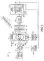
- a system 10 for optical imaging using fluorescent proteins includes an imaging light source 12 and a light directing device 14 to provide a plurality of apparent light sources (not shown).
- the apparent light sources provide excitation light 22a-22c at a variety of positions relative to a specimen 18. While three such positions are shown, there can be more than three or fewer than three apparent light source positions.
- the excitation light 22a, 22c impinges upon the specimen 18, becoming intrinsic light upon entry, and exits the specimen 18 as intrinsic light 24a, 24b.
- the intrinsic light 24a, 24b passes through an optional selectable light filter 28, through an optional image intensifier 30, and is received by a light detector 32.
- the excitation light 22b also passes into the specimen 18 and impinges upon fluorescent proteins 20 within the specimen 18.
- the fluorescent proteins 20 emit fluorescent light 26, which also passes through the optional selectable light filter 28, through the optional image intensifier 30, and is received by the light detector 32.
- An optional white light source 40 can provide further illumination of the specimen, to provide other light paths (not shown), which reflect from a surface of the specimen, and which also pass through the optional selectable light filter 28, through the optional image intensifier 30, and are received by the light detector 32.
- the intrinsic light 24a, 24b, the fluorescent light 26, and the white light from the white light source 40 are simultaneously received by the light detector.
- the intrinsic light 24a, 24b, the fluorescent light 26, and the white light from the white light source 40 can be separated by the selectable filter 28, to provide the different lights to the light detector 32 at the same time or at separate times.
- the selectable filter passband can be centered at different times on the wavelength of the intrinsic light, the fluorescent light, and the white light.
- any one or more of the intrinsic light 24a, 24b, the fluorescent light 26, and the white light from the white light source 40 are received at different times than other ones of the intrinsic light 24a, 24b, the fluorescent light 26, and the white light from the white light source 40.
- the intrinsic light 24a, 24b is received first, at which time, the imaging light source 12 is extinguished.
- the fluorescent light 26 is received after the intrinsic light 24a, 24b is no longer present. After the fluorescent light 26 stops being emitted, the white light source 40 is turned on, and the white light is received.
- the light detector 32 operates to convert the received light into digital data 32a (also referred to herein as image data).
- An image processor 34 receives the digital data 32a and generates an image 46.
- the image 46 is a tomographic image.
- the image processor 34 can include a forward problem (FP) processor 36 having a diffusion equation processor 38. Functions of the forward problem processor 36 and the diffusion equation processor 38 are described more fully below, for example, in conjunction with FIG. 4. Let it suffice here to say that the forward problem processor 36 compares a model of light propagation in the specimen (expected light) with the light received by the light detector. A difference between the received light and the expected light (provided by a light propagation model) is associated with the fluorescent proteins 20 within the specimen.
- the diffusion equation processor 38 provides a modified diffusion coefficient used in a "diffusion equation" associated with a "transport equation” that can be used to provide the above-described light propagation model.
- the modified diffusion coefficient allows the model to predict light propagation for light in the visible wavelength region, having a wavelength of about 400 nm to 700nm. In other embodiments, the modified diffusion coefficient allows the model to predict light propagation for light in the near infrared wavelength region, having a wavelength of about 700 nm to 1000mn. In still other embodiments, the modified diffusion coefficient allows the model to predict light propagation for light having a wavelength outside of the range of 400nm-1000mm
- the system 10 can also include a light direction controller 44 to direct the apparent light sources to predetermined light paths.
- the system 10 can also include an optional chamber position controller 42 in place of or in combination with the light direction controller 44 that can be used to move an imaging chamber 16 to provide more apparent light sources, i.e., the intrinsic light passes through the specimen 18 along more predetermined light paths.
- the system 10 provides a transillumination imaging system for which light generated by the imaging light source 12 passes through the specimen 18 and is received essentially on the other side of the specimen 18.
- a system 70 for which like element of FIG. 1 are shown having like reference designations, the selectable filter 28, the image intensifier 32, and the light detector 32 are positioned generally on the same side of the specimen 18 as the imaging light source 12 and the light directing device 14.
- intrinsic light 72a, 72b is received by the light detector 32 as reflected light.
- the excitation light 22a-22c passes into the specimen 18 and reflects, or more specifically, scatters, back to the light receiver 32.
- Fluorescent light 74 is also received by the light detector 32.
- the system 70 generates an image 76.
- the system 70 provides a reflectance imaging system for which light emitted by the imaging light source 12 passes into the specimen 18 and is received essentially on the same side of the specimen 18.
- an angle between the light directing device 14 and the light detector 32 is approximately ninety degrees.
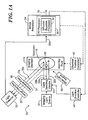
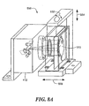
- an apparatus 100 includes a laser 102, an optical fiber 104, and an optical switch 106, which, in combination, generate a plurality of apparent light sources directed toward an imaging chamber 112 having an imaging plate 108 upon which a specimen 110 is placed.
- the imaging chamber can be filled with a matching fluid 114.
- a selectable filter 115 and a CCD camera 116 receive intrinsic light passing through the specimen 110 and fluorescent light emitted by the specimen 110.
- the selectable filter has a passband selectively centered on a wavelength of the intrinsic light or the fluorescent light, depending upon whether an intrinsic image or a fluorescence image is being generated.
- the optical switch 106 can be controlled by a computer 122.
- the computer 122 can also control the CCD camera 116 via a CCD controller 118.
- An image processor 120 receives digital data 116a via the CCD controller 118.
- a graphical display 124 can display resulting image information.
- the laser 102 corresponds to the imaging light source 12 of FIGS. 1 and 1A
- the optical switch 106 corresponds to the light directing device 14 of FIGS. 1 and 1A
- the imaging chamber 112 corresponds to the imaging chamber 16 of FIGS. 1 and 1A
- the CCD camera 116 corresponds to the light detector 32 of FIGS. 1 and 1A
- the image processor 120 corresponds to the image processor 34 of FIGS. 1 and 1A.
- the specimen 110 is shown here to be a mouse placed in the imaging chamber 112.
- the laser 102 provides excitation light (not shown), which enters the specimen 110 and excites fluorescent proteins (not shown) within the specimen 110 to generate fluorescent light (not shown).
- the CCD camera 116 receives the laser light as intrinsic light (having passed through the specimen 110) and also receives the fluorescent light emitted from within the specimen 100 via the selectable filter 115.
- the laser 102 is an Argon (Ar + ) laser emitting laser light at approximately 200mW continuous wave (CW) power having a wavelength of approximately 488nm.
- the laser light can be used to excite the fluorescent proteins within the specimen 110, for example, green or yellow fluorescent proteins.
- the optical fiber 104 is a 100 ⁇ m diameter multimode optical fiber.
- the laser 102 provides a plurality of apparent light sources at different physical positions relative to the specimen 110 by way of the optical switch 106.
- the optical switch provides thirty-one apparent light sources. However, in other embodiments, more than thirty-one or fewer than thirty-one apparent light sources can be provided.
- optical switch 106 is shown, in another embodiment, the optical switch 106 can be replaced with an optical scanning head (or optical scanner), shown in greater detail in FIG. 3.
- optical scanning head or optical scanner
- the optical switch 106 provides apparent light sources at a variety of angles or positions relative to the specimen 110, thereby allowing the image processor 120 to form a corresponding variety of images, which can be combined in a tomographic process by the image processor 120.
- the optical switch 106 includes a plurality of selectable optical fiber paths (not shown), adapted to direct light to a corresponding plurality of selectable fixed physical locations, providing apparent light sources that are selectively fixed in position and number.
- living tissue here shown to be a mouse, is placed on the imaging plate 108, in contact with the optical matching fluid 114.
- the matching fluid 114 is further described below.
- the matching fluid is used to reduce the affect of stray light. However, in other embodiments, no matching fluid is used.
- intrinsic light originating from each of the apparent light sources
- light emitted by fluorescent proteins within the specimen 110 are received by a CCD camera and thereafter tomographically processed by the image processor 120, for example, as described in conjunction with FIG. 4.
- the CCD camera 116 is a cooled CCD camera having reduced dark noise.
- the CCD camera 116 can be provided as a Roper Scientific, Princeton Instruments CCD camera with a cryogenic cooling unit.
- the optical switch 106 is controlled and triggered by the CCD controller 118 so that each obtained image corresponds to a new position of a new apparent light source (i.e., a different light path in the optical switch 106), thus achieving the proper synchronization of excitation and detection.
- Each acquisition is composed of N images, one acquisition for each apparent light source position. Therefore, assuming a 512x512 pixel CCD camera, a maximum number of data for each set of measurements is Nx512x512.
- the number of detectors i.e., pixels
- the number of pixels used for the subsequent processing by the image processor 120 can be smaller than the full group of 512x512 pixels, depending on the field of view associated with each of the apparent light sources. Also, the number of pixels used can be reduced to reduce computational time required for image processing.
- the CCD camera 116 and the selectable filter 115 are selectively movable, for example, in directions represented by arrows 140, 142 about the specimen 110 in order to achieve more images at other angles relative to the specimen 110.
- an optical scanner 117 somewhat offline from the CCD camera 116, can provide images at other angles relative to the specimen.
- the specimen 110 can be placed horizontally on the imaging plate 108 and compressed with a covering glass (not shown).
- the imaging chamber 112 is then filled with the matching fluid 114, which, in one particular embodiment, is comprised of an intralipid and India ink solution.
- the matching fluid 114 provides a match of optical properties, which tends to reduce the index of refraction and diffuse-wave mismatches in the chamber.
- the reduced scattering coefficient is further described below.
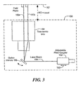
- an optical scanner 150 can be used in place of the optical switch 106 of FIG. 2 and can also be used as the optical scanner 117 of FIG. 2.
- the optical scanner 150 can include two galvanometer controlled mirrors (here one galvanometer controlled mirror 156 is shown for clarity), pivoting about generally orthogonal axes, and a scan lens 158 to scan and focus a laser beam 156 onto an input window of an imaging chamber 162 to provide a plurality of apparent light sources, each at a different physical position, here represented by light beams 160a and 160b.
- the scan lens 158 is a telecentric lens.
- a light beam diameter at a field plane 162 e.g., imaging chamber 112 of FIG. 2 is approximately 300 ⁇ m.
- a single light source (not shown) can be used, which is received by a fiber coupler 152.
- the optical scanner 150 provides less optical loss compared to optical losses of a conventional optical switch, e.g., the optical switch 106 of FIG. 2. Thus, the optical scanner 150 provides a lower loss apparent light source system. Furthermore, with the optical scanner 150, a scanning area, a light beam shape, as well as a number of apparent light sources and apparent light source positions can be substantially infinitely varied, unlike the optical switch 106 of FIG. 2, for which a fixed number of light paths are in fixed positions. Also, a higher light power and a wider light wavelength range (visible light to near infrared (NIR) light) can be achieved.
- NIR near infrared
- the optical scanner 150 has a variety of advantages over an optical switch, including, but not limited to, lower energy losses, uniform response over a number of apparent light sources, and improved reliability and robustness. Also, a scanning area as well as a number and spatial configuration of the apparent light sources can be software controlled and can, therefore, be varied in accordance with characteristics of the specimen being scanned. Furthermore, higher power illumination and a wider wavelength range (e.g., from 400 to 1000 nanometers) can be achieved.
- a method 200 of optical tomography begins at step 202, where excitation light is generated and transmitted toward a specimen.
- the excitation light is provided from a plurality of apparent light sources corresponding to different positions relative to the specimen.
- the plurality of light sources provides excitation light generally simultaneously at the plurality of apparent light sources. In other embodiments, the plurality of apparent light sources provides excitation light sequentially.
- intrinsic light is received.
- the intrinsic light corresponds to the excitation light having passed into and out of the specimen.
- the intrinsic light can be received with a light detector, for example, the light detector 32 of FIG. 1.
- the received intrinsic light corresponds to transillumination light, wherein the light detector and the apparent light sources are essentially on opposite sides of the specimen.
- the received intrinsic light corresponds to reflectance light, wherein the light detector and the apparent light sources are essentially on the same side of the specimen.
- fluorescent light is received.
- the fluorescent light is emitted by fluorescent proteins within the specimen in response to the intrinsic light.
- the fluorescent light can be received with a light detector, for example, the light detector 32 of FIG. 1.
- the fluorescent light and the intrinsic light are received at the same time, for example, by way of optical filters (e.g., 28, FIG. 1) adapted to separate the fluorescent light from the intrinsic light.
- the fluorescent light is received after the excitation light is extinguished, also by way of an optical filter.
- the received intrinsic light is converted to first image information, for example, digital data 32a of FIG. 1.
- the received fluorescent light is converted to second image information, which can also be digital data 32a.
- a model is generated to predict light propagation in the specimen.
- the model can be based on the diffusion equation having a modified diffusion coefficient as described more fully below, for example, as in Eq. (4) below and having a modified wave number as in Eq. (6) below.
- the optical model generated at block 212 can be associated with propagation in a homogenous medium, i.e. a medium that has no optical heterogeneity. In other embodiments, more advanced models can be also utilized to resolve and then employ information on background optical heterogeneity.
- the modified diffusion equation having a modified diffusion coefficient, wherein the modified diffusion coefficient is adapted to predict characteristics of light propagation for a diffuse medium in which the medium has relatively high absorption, as ,for example, in cases of visible light propagating in biological tissue.
- the modified diffusion equation can predict, for example, the propagation of visible light in biological tissue, which is known to be diffuse and have relatively high absorption of visible light.
- the modified diffusion equation is also suited to accurately predict the propagation of light having other wavelengths traveling in a diffuse medium, for example, near infrared light propagating in biological tissue.
- the general diffusion equation can be derived from a Radiative Transport Equation. Both the intrinsic light field, which is generated by the laser excitation light (intrinsic light) propagating inside the medium, and the fluorescent light field, which is generated inside the medium due to a fluorescent protein at a position F, are calculated independently and then used to calculate a normalized Born field (the diffusion approximation). As described more fully below, a modified diffusion equation can be used in forward problem to provide an image of the fluorescent proteins inside the medium.
- U c r ⁇ s ⁇ r ⁇ d S o ⁇ U fl ( r ⁇ s , r ⁇ d ) - ⁇ f ⁇ U inc ( r ⁇ s , r ⁇ d )
- U inc ( r ⁇ s , r ⁇ d ) 1 U o ⁇ r ⁇ s - r ⁇ , k ⁇ 1 ⁇ d 3 ⁇ r ⁇ U o ⁇ r ⁇ s - r ⁇ , k ⁇ 1 ⁇ n r ⁇ ⁇ ⁇ D ⁇ ⁇ 2 ⁇ G
- So is a gain term that accounts for instrument gain differences (e.g., light detector gain differences) at the excitation ( ⁇ 1 ) and emission ( ⁇ 2 ) wavelengths
- n r ⁇ is a product of a fluorescent protein absorption coefficient and fluorescence quantum yield
- k ⁇ 1 k- ⁇ 2 are modified photon wave propagation wave numbers at ⁇ 1 and ⁇ 2 respectively which account for high absorption
- ⁇ is the speed of light in the medium
- D ⁇ 2 is the modified diffusion coefficient in the presence of the high absorption at ⁇ 2
- k ⁇ 1 is a term that describes the established photon field at position r ⁇ in the medium at ⁇ 1
- G ( r ⁇ d - r ⁇ , k ⁇ 2 ) is the Green's function solution to the diffusion approximation that describes the propagation of the emission photon wave from a fluorescent protein at position r ⁇ to the light detector.
- G ( r ⁇ d - r ⁇ , k ⁇ 2 ) exp ik ⁇ 2 ⁇ r ⁇ d - r ⁇ r ⁇ d - r ⁇
- Equation (1) above is essentially normalized by U inc .
- An advantage of using the normalization in equation (1) is that position-dependent contributions are eliminated, and also, this field can be calculated even with the presence of the fluorescent proteins. This means that no background measurements are necessary before the administration of the fluorescent protein, which is important for in vivo studies.
- the coefficient ⁇ s ' is the reduced scattering coefficient, and ⁇ a is the absorption coefficient.
- D ⁇ 1 3 ⁇ ⁇ s ⁇ ⁇ + ⁇ a ( 1 - 4 5 ⁇ ⁇ a ⁇ s ⁇ ⁇ ⁇ 1 + g + ⁇ a ⁇ ) - 1 where g is an anisotropy factor.
- D ⁇ is expressed in terms of the reduced scattering coefficient ⁇ s ' , which is a relevant quantity in scattering experiments in anisotropic media.
- Typical values of ⁇ range from 0.2 to 0.6.
- ⁇ is on the order of 0.50 to 0.55, assuming an anisotropy factor of g ⁇ 0.8, which is typical for biological tissue.
- the dependence of ⁇ with g is small, and changes in the value of g within realistic biological values (g between 0.5 and 0.9) give small changes in the value of ⁇ .
- Green's function solutions to the diffusion approximation can be derived that are appropriate for imaging in the presence of high absorption, e.g., for visible light propagating in biological tissue.
- the first image information, the second image information, and the light propagation model are combined, for example, in a so-called "forward model.”
- the unknown distribution corresponds to the fluorescent light emitted by the fluorescent proteins.
- the image processor 34 can solve for the unknown distribution in order to establish physical positions and characteristics of the fluorescent proteins 20 (FIG. 1) in the specimen 18 (FIG. 1).
- a map is generated of the fluorescent protein concentration in the specimen.
- the map is a tomographic image.
- the above-described forward model is "inverted" to solve for the above-described unknown distribution.
- the volume of interest can be segmented into axial (horizontal) layers (e.g., 21 layers) each containing a number (e.g., 651) of voxels.
- the voxel size is selected based upon the dimension of the field of view and the number of segmentations.
- the volume of interest can be segmented in a number of voxels in three dimensions. These can be seen as horizontal, vertical, or transverse layers, resembling cubes stacked next to each other in three dimensions.
- Each of the voxels has an unknown amount of fluorescent proteins and an unknown attenuation. If the fluorescence and attenuation in each of the voxels were known, the measured images could be predicted. However the fluorescence and attenuation in each voxel are not known. Therefore the above-described forward problem can be solved (inverted) to find the map of the fluorescent proteins.
- the specimen can be illuminated by a white light source at block 218 and a white light can be received at block 220 and a white light image can be generated at block 222.
- the white light image generated at block 222 can be superimposed at block 224 with the fluorescent protein map generated at block 216. To this end, in one particular embodiment, the white light image is registered or aligned with the map of the fluorescent proteins.
- an image of the apparent light sources can be made, for example, through a phantom, to allow the apparent light source coordinates to be determined. This procedure improves the co-registration of a white light image that can be superimposed upon tomographic images, reducing relative positional errors.
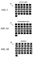
- thirty-one images 300 of intrinsic light correspond to thirty-one apparent light sources directing light at a specimen and intrinsic light received as transillumination light therefrom.
- the apparent light sources direct light at the specimen either one at a time or at the same time, or in any combination.
- the images 300 can be generated using a bandpass interference filter (e.g., 28, FIG. 1) centered on the wavelength of the excitation light from the light source (e.g., 12, FIG. 1).
- a bandpass interference filter e.g., 28, FIG. 1 centered on the wavelength of the excitation light from the light source (e.g., 12, FIG. 1).
- thirty-one images 310 of fluorescent light correspond to the thirty-one apparent light sources directing light at a specimen and emitted fluorescent light received therefrom.
- the apparent light sources direct light at the specimen either one at a time or at the same time, or in any combination.
- the fluorescent light can be received either while the apparent light sources are directing light at the specimen or after the apparent light sources direct light at the specimen.
- the intrinsic light images of FIG. 5 and the fluorescent light images of FIG. 5A are combined, for example at block 214 of FIG. 4.
- the images 310 can be generated using a band-pass interference filter (e.g., 28, FIG. 1) centered on the wavelength of the emitted light from the fluorescent proteins (e.g., 20, FIG. 1).
- a band-pass interference filter e.g., 28, FIG. 1 centered on the wavelength of the emitted light from the fluorescent proteins (e.g., 20, FIG. 1).
- the measurements (or images) 300, 310 are used to generate the field U c ( r ⁇ s , r ⁇ d ) described by Eq. (1). Exposure times can be varied between individual images so that dynamic range is maximized.
- thirty-one images 320 of the apparent light sources correspond to the thirty-one apparent light sources directing light through a phantom and light received therefrom.
- the apparent light sources direct light at the phantom either one at a time or at the same time, or in any combination.
- the images of the apparent light sources are used optionally, for example, to register a white light image with a map of fluorescent protein concentration as shown at block 224 of FIG. 4.
- the images 320 can be generated using a band-pass interference filter (e.g., 28, FIG. 1) centered on the wavelength of the excitation light from the white light source (e.g., 40, FIG. 1).
- a band-pass interference filter e.g., 28, FIG. 1 centered on the wavelength of the excitation light from the white light source (e.g., 40, FIG. 1).
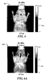
- FIGS. 6 and 6A an example of images provided by the method and system of the present invention is shown.
- Two different numbers of green fluorescent protein (GFP) expressing tumor cells were used: 10 5 and 10 6 .
- the fluorescent proteins were placed inside thin glass tubes and inserted in the esophagus of animals after they had been sacrificed.
- the animals were placed inside the imaging chamber (e.g., 16, FIG. 1), which was then filled with the matching fluid described above. Imaging was performed using the 31 apparent light source array transilluminating the area around the chest of the animal.
- an image 350 includes a map 352 of the 10 5 fluorescent proteins, upon which a white light image 354 of a mouse is superimposed.
- an image 370 includes a map 372 of 10 6 fluorescent proteins, upon which a white light image 374 of the mouse is superimposed.
- a system 400 for optical tomography 400 includes a laser source 402 coupled to an optical scanner 412, which provides a plurality of apparent light sources, as described, for example, in conjunction with FIG. 3.
- the system 400 also includes a laser intensity controller 406 (LIC).
- the LIC 406 provides intensity control to the laser source 402.
- the system 400 further includes an image intensifier 420 and a CCD camera.
- a selectable light filter 418 is selectively band centered at the wavelength of the excitation light transmitted by the apparent light sources or at the wavelength of the light emitted by fluorescent proteins within a specimen 416.
- a computer 424 can control the LIC 406 and the optical scanner 412. The computer can also function as an image processor, for example, as the image processor 34 of FIG. 1, providing images on a graphical display 426.
- the optical scanner 412 provides a plurality of apparent light sources at a corresponding plurality of positions relative to the specimen 416.
- the CCD camera collects both intrinsic light passing though the specimen 416 as transillumination light and also fluorescent light emitted by fluorescent proteins within the specimen 416.
- the CCD camera converts the received light into digital data, which the computer processes as described above in conjunction with FIG. 4, to provide a tomographic image on the graphical display 426.
- a plurality of images necessary for tomographic imaging are associated with positions of the plurality of apparent light sources provided by the optical scanner 412, and the imaging chamber remains substantially stationary, but can be moved along an axis 417 to affect image quality.
- the imaging chamber 414 of FIG. 7 includes a cylinder 450, which can be filled with a matching fluid as described, for example, in conjunction with FIG. 2.
- An imaging plate 454 and a cover glass 456 surround the specimen 416.
- a system 500 for optical tomography includes an imaging chamber 504 holding a specimen 510.
- the imaging chamber 504 is adapted to rotate as represented by an arrow 506 and to move in translation along an axis 508.
- the system 500 can include a rotation stage 502 to hold the imaging chamber 504.
- a plurality of images necessary for tomographic imaging is associated with positions of the plurality of apparent light sources provided by the optical scanner 412.
- the imaging chamber 504 can be moved in rotation and in translation, for example, under control of computer 424, to provide further apparent light source positions and/or angles, to provide further images of the specimen 510.
- FIG. 8A in which like elements of FIGS. 7 and 8 are shown having like reference designations, the imaging chamber 504 of FIG. 8 can be replaced with an imaging chamber 550 as shown, for example in FIG. 7A, but adapted to move in rotation as represented by an arrow 552 and to move in translation as represented by an arrow 554.
- the imaging chamber 550 is also able to move in translation along an axis represented by and arrow 556, which allows for images obtained by the CCD camera 442 of FIG. 8 to be affected.
- FIG. 9 another system for optical tomography 600, in which like elements of FIG. 7 are shown having like reference designations, includes a generally cylindrical imaging chamber 602 in which a specimen 604 is placed.
- the imaging chamber 602 can rotate as represented by an arrow 606.
- the rotation can be computer controlled, for example, with a rotation stage controller 612 controlled by a computer 608.
- the LIC 406, FIG. 7 is not shown but can be included in the system 600.
- a plurality of images necessary for tomographic imaging is associated with positions of the plurality of apparent light sources provided by the optical scanner 412.
- the imaging chamber 602 can be rotated, for example under computer control, i.e., to provide further apparent light source positions and/or angles, to provide further images of the specimen 604.
- An advantage of the cylindrical imaging chamber 602 is that both the rotation as well as the imaging algorithm are simple and fast, without imposing drawbacks on the image quality.
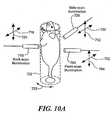
- yet another system 700 for optical tomography includes a laser source 710, which provides light to an optical fiber 712.
- the optical fiber 712 is selectively movable along at least two axes 718, 720, for example, by a structure 716.
- the system 700 can also include a generally cylindrical imaging chamber 722 in which a specimen 724 is placed.
- the imaging chamber 722 can rotate as represented by an arrow 723.
- the rotation can be computer controlled, for example, with a rotation stage controller 744 controlled by a computer 740.
- motion of the structure 716, which provides motion of the fiber 712 on the at least two axes 718, 720 can be computer controlled, for example, with an XY-stage controller 746 controlled by the computer 740.
- the LIC 406, FIG. 7 is not shown but can be included in the system 700.
- intrinsic light passing though the specimen 724 and fluorescent light emitted from within the specimen 724 pass through a selectable light filter 734 and are received by an image intensifier 736 and a CCD camera 738.
- the CCD camera provides digital data 738a to the computer 740, which provides at least the processes shown in blocks 208-216 of FIG. 4, and which provides a map of fluorescent proteins within the specimen 724 on a graphical display 742.
- Another optical fiber 714 can provide a second light source 726 on the opposite side of the specimen 724 from the optical fiber 712.
- the second light source 726 can be a single white light source used to provide the white light image of blocks 218 to 224 of FIG. 4.
- the second light source 726 can be selectively moved in at least two axes 730, 732 to provide another plurality of apparent light sources used in reflectance imaging of the specimen 724, in much the same way as shown, for example, in FIG. 1A.
- an advantage of the system 700 is that it can work in reflectance mode as well as transillumination mode and can implement any geometry, for example, a free-space (i.e., non-contact and no matching fluid) cylindrical geometry.
- a third light source 760 can be provided to achieve even more apparent light sources.
- the third light source 760 is selectively moveable along at least two axes 762, 764, providing, for example, both side illumination with the second light source 726 and front illumination with the third light source 760.
- Side illumination and front illumination can be used to improve the collection efficiency of low level light signals, especially signals otherwise hidden by large absorbers in transillumination mode using the first light source 719.
- Measurements resulting from the first, second and third light sources 719, 726, 760, respectively, can be combined with tomographic processing and used to solve a forward problem similar to that described above in conjunction with FIG. 4.
- another imaging system 800 includes a laser light source 802 to generate excitation light and a single optical fiber 804.
- the optical fiber 804 is coupled to an optical splitter 806, which spits the excitation light to a both a plurality of optical fibers 808a-808N and to an optical fiber 810, each carrying the excitation light.
- the optical fibers 808a-808N couple to a scanning head 812, which can move in translation along at least two axes represented by arrows 814, 816.
- the optical fibers 808a-808N provide apparent light sources, which project excitation light at the same time toward a specimen 822 disposed within an imaging chamber 820 (or imaging chamber).
- intrinsic light exiting the specimen 822 and also fluorescent light emitted by fluorescent proteins within the specimen 822 passes through a selectable filter 828, through an image intensifier 830, and into a CCD camera 832.
- the light is converted to digital data 832a by the CCD camera 832, which is received by a computer 834.
- the computer 834 processes the digital data as described, for example, by the process 200 of FIG. 4, and can present a graphical display of tomographic images on the graphical display 836.
- a white light source 826 can generate white light, which reflects from the specimen 822, providing white light though the selectable filter 828, through the image intensifier 830, and into the CCD camera. As described in conjunction with FIG. 4, the white light image of the specimen 822 can be superimposed with a map of the fluorescent proteins within the specimen 822, resulting in a more understandable tomographic image.
- the computer 834 can also control the position of the scanning head 812 via an XY stage controller 838, moving the scanning head about axes as represented by the arrows 814, 816 to provide more apparent light sources, resulting in a better tomographic map of the fluorescent proteins.
- the scanning heard 812 can be scanned along at least two axes represented by arrows 814, 816 and all of the optical fibers 808a-808N coupled to the scanning head 812 can be illuminated at the same time.
- Advantages of such an embodiment include, but are not limited to, faster tomographic imaging, particularly in the presence of low amplitude light signals, which result in long exposure times.
- Crosstalk between the fibers 808a-808N can be minimized by appropriate selection of distances between the individual fibers 808a-808N so that the paths of the propagating photons do not overlap.
- the fibers 808a-808N can be illuminated one at a time to eliminate noise from crosstalk between the fibers 808a-808N.
- the optical splitter 806 can be replaced by an optical switch, (e.g., 106, FIG. 2).
- a single fiber can be scanned along axes represented by arrows 814, 816.
- the scanning head 812 of FIG. 11 has a plurality of apertures 850a-850N, each of which correspond to a respective apparent light source, forming N apparent light sources.
- N apparent light sources When the scanning head 812 is moved along an axis, for example axes represented by arrows 814, 816, further apparent light sources are formed, for example, another N apparent light sources.
- the method and system of the present invention can use any fluorescent proteins, including, but not limited to, DsRed and HcRed fluorescent proteins. These particular fluorescent proteins provide fluorescent light in the red or near-infrared region of the visible light spectrum. These particular fluorescent proteins can result in maps of fluorescent proteins having higher quality because the red region of the visible spectrum of light has a higher efficiency deep penetration depth in biological tissue compared with other wavelengths of visible light and can provide higher resolution than longer wavelength NIR systems.
- the method and system of the present invention can be used for studying tumor growth and monitoring of metastasis formation when used with tumor cells that express fluorescent proteins (like GFP).
- the method and system of the present invention can be used with GFP expressing tumor cells and YFP expressing viral cells for the study of gene delivery and gene therapy for specific patient targeted treatment.
- the method and system of the present invention can also take advantage of imaging modalities using algorithms for imaging arbitrary geometries without the need matching fluids.
- the algorithms for modeling of light propagation and solving forward problems can be applied to all of the above system embodiments.
- the method and system of the present invention when using visible light, provides higher spatial resolution than conventional tomographic approaches using near-infrared (NIR) light.
- NIR near-infrared
- the excitation light and resulting emitted fluorescent light can be continuous wave (CW) light, intensity modulated (IM) or time-resolved (TR) light, or a combination of both.
- the method and system of the present invention can give information on the dynamics of the system as function of time, and the resulting image can be co-registered with an image obtained by another imaging method such as magnetic resonance imaging (MRI), computed tomography imaging (CT), ultrasound or bioluminescence imaging.
- MRI magnetic resonance imaging
- CT computed tomography imaging
- ultrasound or bioluminescence imaging bioluminescence imaging
- This above described system and method use a modified diffusion approximation, combined with appropriate normalization, which enables three-dimensional tomographic imaging of fluorescent proteins in-vivo in a visible wavelength range of at least 400nm to 700nm in a medium having a relatively high absorption coefficient (e.g., >0.3 cm -1 ), i.e., which is diffuse.
- the modified diffusion approximation does not require the use of the more complex transport equation. Therefore the modified solutions obtain computational efficiency.
- non-contact tissue illumination and/or non-contact light reception is used, wherein the above-described apparent light sources and/or light detector are spaced apart from the specimen being scanned. In other embodiments, the apparent light sources and/or the light detector are placed in substantial contact with the specimen,
- fluorescent proteins can be used to monitor tumor growth, metastasis formation, gene expression, and therapeutic effects.
- the method and system can be used to provide non-invasive, whole-body molecular imaging to non-invasively yield information associated with activity at subcellular levels.
- the method and system of the present invention can provide insight into specific molecular and biological abnormalities that form the basis of many diseases, e.g., cancer, tumor growth, and metastasis formation.
- the method and system can also be used to image angiogenesis since the high absorption of hemoglobin contrasts the vessels against the fluorescent background of the tumor cells.
- the method and system can be used to assess efficacy of novel targeted therapies at a molecular level. This, in turn, can have an impact on drug development, drug testing, and choosing appropriate therapies and therapy changes in a given patient.
- the method and system enable study of the genesis of diseases in the intact microenvironment of living systems. And, still further, the method and system are useful for testing novel gene delivery strategies.
- the imaging method and system allow acquisition of three-dimensional information much faster than is currently possible with time consuming and labor intensive conventional basic science techniques.
- the method and system of the present invention have broad applications in a wide variety of biologic, immunologic, and gene therapies designed to promote the control and eradication of a variety of diseases including cancer, neurodegenerative, inflammatory, infectious, and other diseases. Furthermore, the method and system have broad applications for seamless disease and treatment in combined settings.
Abstract
Description
- This invention relates generally to optical tomography and, more particularly, to a method and system for extracting quantitative, three-dimensional molecular and biological information from living specimens using fluorescent proteins.
- Fluorescent proteins (FPs) are important reporter molecules for different biomedical applications. In some existing applications, engineered FPs are detected by epi-fluorescence, confocal (microscopy), or reflectance (whole animal) imaging.
- Epi-fluorescence, confocal microscopy depends on coherent (non-diffuse) light projected toward and reflected from a specimen. Because microscopy requires substantially coherent light, this technique is only able to image to a small depth (e.g., less than 1mm) into the specimen. At deeper imaging depths, light is known to become diffuse, rendering microscopy ineffective at the deeper imaging depths.
- Reflectance fluorescence imaging has been shown to be useful in detecting and following tumors in vivo, particularly those implanted near the surface or in surgically exposed organs. However, reflectance fluorescence imaging has inherent limitations, since obtained images are a superposition of fluorescence signals from multiple depths, which tends to result in blurred images. Furthermore, reflectance fluorescence imaging is not tomographic and does not retrieve depth information or allow absolute quantification of fluorescence activity. This is due in part to non-linear light attenuation and propagation in biological tissues, which limits the applicability of reflectance fluorescence imaging to semi-quantitative imaging at depths of only a few millimeters.
- Imaging optical signatures deeper in tissues often requires the application of advanced light excitation and light detection apparatus and techniques and the use of tomographic principles for combining data acquired at different projections. Advances in imaging with diffracting light sources have resulted in several studies investigating tissue using intrinsically or extrinsically administered optical contrast. In particular, diffuse optical tomography (DOT) is a technique that can provide a tomographic image associated with a diffuse media in the presence of absorption and scattering in the diffuse media. For example, DOT has been applied to cerebral hemodynamic imaging and imaging of breast tissue. One exemplary. DOT method and system is described, for example, in
international patent application PCT/US04/03229 , by Vasilis Ntziachristos and Jorge Ripoll, entitled "Method and System for Free Space Optical Tomography of Diffuse Media," filed February 5, 2004, which application is assigned to the assignee of the present invention. - It has been shown that light with wavelengths in the near-infrared range can propagate through tissue for distances on the order of several centimeters because of low tissue absorption in the so-called "near-infrared window." The near-infrared (NIR) window has enabled the development of NIR fluorescence techniques to visualize specific biochemical events inside living specimens.
- A variety of related methods for processing NIR fluorescent signals have also been developed. In particular, development of appropriate imaging systems has enabled the application of Fluorescence Molecular Tomography (FMT), a technique that resolves molecular signatures in deep tissues using NIR fluorescent probes or markers. FMT used for in vivo three-dimensional imaging of enzymatic activity in deep-seated tumors has been demonstrated.
- A common assumption in conventional NIR optical tomography is that propagation in a diffuse media has high scattering but relatively low absorption, as provided by the NIR window. This assumption has allowed derivation of a "diffusion equation" associated with a "transport equation," by means of a "diffusion approximation," which provides an effective tool for modeling NIR photon propagation in tissues. The transport equation is described, for example, in K.M. Case and P.F. Zweifel, "Linear Transport Theory," Addison-Wesley, MA, (1967) and in K. Furutsu and Y. Yamada, "Diffusion Approximation for a Dissipative Random Medium and the Applications," Phys. Rev. E 50, 3634 (1994).
- As is known, all currently available fluorescent proteins utilize excitation light having a wavelength in the visible range. Moreover, conventional fluorescent proteins emit visible fluorescent light when excited. Tomographic imaging using visible light, as provided by the conventional fluorescent proteins, is complicated by a relatively high absorption of visible light propagating in biological tissue, which results in significant attenuation. With high absorption, (e.g., for visible light) the conventional diffusion approximation described above is not valid.
- Other, more advanced solutions (other than the above-described diffusion approximation) to the transport equation have been generated and applied to NIR. optical tomography. The advanced solutions overcome the inadequacy of the above-mentioned diffusion approximation. However the advanced solutions to the transport equation are generally computationally expensive and become impractical for tomographic systems having a large number of excitation light sources, resulting in large data sets.
- In order to provide a plurality of images necessary for tomography, many conventional optical tomography systems use an optical switch as part of a light source assembly in order to use a single light element to project at a variety of angles or positions relative to a specimen. It is known that the optical switch generates energy losses. Furthermore, many optical tomography systems use a CCD camera at room temperature or at moderate cooling to collect light. It is known that a room temperature or moderately cooled CCD camera exhibits a relatively high level of dark (thermal) noise, which tends to limit the quality of resulting optical tomography images.
- In accordance with an aspect of the present invention, a system for optical tomography includes an apparent light source adapted to project excitation light toward a specimen having fluorescent proteins therein, wherein the excitation light enters the specimen becoming intrinsic light within the specimen. The intrinsic light is adapted to excite fluorescent light from the fluorescent proteins. The intrinsic light and the fluorescent light are diffuse. In some embodiments, at least one of the excitation light and the fluorescence light has a wavelength in the visible wavelength range.
- In accordance with another aspect of the present invention, a method of optical tomography includes generating excitation light with an apparent light source adapted to project the excitation light toward a specimen having fluorescent proteins therein, wherein the excitation light enters the specimen becoming intrinsic light within the specimen. The intrinsic light is adapted to excite fluorescent light from the fluorescent proteins. The intrinsic light and the fluorescent light are diffuse. In some embodiments, at least one of the excitation light and the fluorescent light has a wavelength in the visible wavelength range.
- In accordance with another aspect of the present invention a system for optical tomography includes at least one selectively movable component to selectively move an apparent light source to direct a plurality of light paths toward a specimen.
- The foregoing features of the invention, as well as the invention itself may be more fully understood from the following detailed description of the drawings, in which:
- FIG. 1 is a block diagram showing a system for optical tomography, which provides transillumination imaging;
- FIG. 1A is a block diagram showing a system for optical tomography, which provides reflectance imaging;
- FIG. 2 is a block diagram showing a system for optical tomography having a laser source, an optical fiber, an optical switch, a cooled CCD camera, and an image processor;
- FIG. 3 is a block diagram of an optical scanner having a fiber coupler, a position-controlled mirror, and a telecentric lens, together used for generation of a plurality of apparent light sources having a flat light field at a constant working distance (WD);
- FIG. 4 is a flow chart showing a process used to provide a tomographic image in accordance with the present invention;
- FIG. 5 shows a series of thirty-one images, corresponding to the thirty-one apparent light sources of FIG. 1 as provided by the optical scanner of FIG. 3, showing intrinsic light (i.e., excitation light from the apparent light sources having entered and exited a specimen);
- FIG. 5A shows another series of thirty-one images, corresponding to the thirty-one apparent light sources of FIG. 1 as provided by the optical scanner of FIG. 3, showing fluorescent light emitted from fluorescent proteins within a specimen in response to the intrinsic light of FIG. 5;
- FIG. 5B shows yet another a series of thirty-one images, corresponding to the thirty-one apparent light sources of FIG. 1 as provided by the optical scanner of FIG. 3, showing the transmitted light not having passed though the specimen, but having passed through a homogeneous slab (i.e., a phantom);
- FIG. 6 shows a fluorescence image superimposed with a white light image of a dead mouse having a glass vial with green fluorescent protein (GFP) expressing cells placed into the esophagus;
- FIGS. 6A shows another fluorescence image superimposed with a white light image of a dead mouse having another glass vial with green fluorescent protein (GFP) expressing cells placed into the esophagus, the glass vial having a higher number of cells than the vial of FIG. 6;
- FIG. 7 is a block diagram of a system for optical tomography having a planar imaging chamber;
- FIG. 7A is a block diagram showing an imaging chamber used in the system of FIG. 7;
- FIG. 8 is block diagram of an alternate system for optical tomography having a rotating planar imaging chamber;
- FIG. 8A is block diagram of a rotating planar imaging chamber that can be used in the system of FIG. 8;
- FIG 9 is a block diagram of another alternate system for optical tomography having a rotating cylindrical imaging chamber;
- FIG. 10 is a block diagram yet another alternate system for optical tomography having a rotating cylindrical imaging chamber and a selectively movable apparent light source;
- FIG 10A is a block diagram showing a rotating cylindrical imaging chamber and a plurality of light sources;
- FIG. 11 is a block diagram yet another alternate system for optical tomography having an optical scanning head having array of apparent light sources; and
- FIG. 11A is a block diagram of the optical scanning head as shown in FIG. 11.
- Before describing the imaging method and system, some introductory concepts and terminology are explained. As used herein, a "phantom" refers to a test object being imaged. A phantom is typically a manufactured article having diffuse light propagation characteristics similar to living tissue, for example, a piece of plastic. For another example, a phantom can be a vial having cells expressing the fluorescent proteins therein, i.e. a fluorescent marker.
- As used herein, the term "apparent light sources" is used to describe projections of a single light source to a plurality of physical positions or angles, each providing an apparent light source.
- As used herein, the term "excitation" light is used to describe light generated by an excitation light source, (for example, an apparent light source) that travels toward a specimen to be imaged, before entering the specimen. Once in the specimen, the light is referred to herein as "intrinsic" light. The intrinsic light is subject to absorption and scattering in the specimen and can also exit the specimen.
- The intrinsic light, having exited the specimen, is at the same wavelength at which it was generated by the excitation light source. The excitation and intrinsic light can be monochromatic or they can cover a broader spectrum, for example, as white light.
- In some embodiments, the intrinsic light exiting the specimen is received by a light detector device disposed generally on the same side of the specimen as the light source (for example, in reflectance imaging of FIG. 1A described below). In other embodiments, the intrinsic light exiting the specimen is received by a light detector disposed generally on the opposite side of the specimen as the excitation light source, after it passes through the specimen (for example, in transillumination imaging of FIG. 1 described below). In either case, the excitation light becomes intrinsic light when it enters the specimen and either reflects from the inside of the specimen or passes through the specimen.
- As used herein, the terms "emitted" light is used to describe light generated by or within a biological tissue. As used herein, the term "fluorescence" or "fluorescent" light is used to describe a form of emitted light generated via excitation of a fluorescent protein in response to the intrinsic light.
- As used herein, the term "image" is used to describe a visual representation having underlying "image data" generated by a digital camera or by a computer system. However, it will be understood that the term "image," as used herein, is also used to refer to the image data.
- As used herein, the term "diffuse" is used to describe light having photons that have encountered several scattering events (for example, more than ten scattering events) when propagating inside a specimen, independent of absorption of the photons in the specimen. The number of scattering events can be more than or less then ten.
- The method and system of the present invention are described below to apply to visible light propagating in a biological tissue for which diffuse light propagation dominates. However, the method and system apply equally well to any form of light propagating in any medium for which diffuse propagation dominates, for example, NIR light propagating to a distance sufficiently deep in biological tissue, for example, visible excitation light and NIR fluorescent (emitted) light. Also, the method and system can also be applied to light propagating in a medium for which coherent propagation dominates.
- While the method and system of the present invention are described herein as applied to fluorescent proteins that emit visible fluorescent light, providing particular benefits in the visible wavelength range of about 400mn to 700nm, the method and system can also be applied to light having other wavelengths, for example to fluorescent light in the near infra red (NIR) range of about 700nm to 1000mn. Also, the method and system apply equally well to a system in which excitation light is in one wavelength range, for example, in the visible range, and the fluorescent light emitted by the fluorescent proteins is in another wavelength range, for example in the NIR range. The method and system also apply where both the excitation light and the fluorescent light emitted by the fluorescent proteins are in the NIR range or both are in the visible range. Also, light beyond the wavelength range of 400nm to 1000nm can be used.
- Referring to FIG. 1, a
system 10 for optical imaging using fluorescent proteins includes animaging light source 12 and alight directing device 14 to provide a plurality of apparent light sources (not shown). The apparent light sources provideexcitation light 22a-22c at a variety of positions relative to aspecimen 18. While three such positions are shown, there can be more than three or fewer than three apparent light source positions. Theexcitation light specimen 18, becoming intrinsic light upon entry, and exits thespecimen 18 asintrinsic light intrinsic light light filter 28, through anoptional image intensifier 30, and is received by alight detector 32. Theexcitation light 22b also passes into thespecimen 18 and impinges uponfluorescent proteins 20 within thespecimen 18. In response to theexcitation light 22b thefluorescent proteins 20 emitfluorescent light 26, which also passes through the optional selectablelight filter 28, through theoptional image intensifier 30, and is received by thelight detector 32. - An optional white
light source 40 can provide further illumination of the specimen, to provide other light paths (not shown), which reflect from a surface of the specimen, and which also pass through the optional selectablelight filter 28, through theoptional image intensifier 30, and are received by thelight detector 32. - In some embodiments, the
intrinsic light fluorescent light 26, and the white light from thewhite light source 40 are simultaneously received by the light detector. In this arrangement, theintrinsic light fluorescent light 26, and the white light from thewhite light source 40 can be separated by theselectable filter 28, to provide the different lights to thelight detector 32 at the same time or at separate times. To this end, the selectable filter passband can be centered at different times on the wavelength of the intrinsic light, the fluorescent light, and the white light. - In other embodiments, any one or more of the
intrinsic light fluorescent light 26, and the white light from thewhite light source 40 are received at different times than other ones of theintrinsic light fluorescent light 26, and the white light from thewhite light source 40. For example, in one particular embodiment, theintrinsic light imaging light source 12 is extinguished. Thefluorescent light 26 is received after theintrinsic light fluorescent light 26 stops being emitted, thewhite light source 40 is turned on, and the white light is received. - The
light detector 32 operates to convert the received light intodigital data 32a (also referred to herein as image data). Animage processor 34 receives thedigital data 32a and generates animage 46. In some embodiments, theimage 46 is a tomographic image. - The
image processor 34 can include a forward problem (FP)processor 36 having adiffusion equation processor 38. Functions of theforward problem processor 36 and thediffusion equation processor 38 are described more fully below, for example, in conjunction with FIG. 4. Let it suffice here to say that theforward problem processor 36 compares a model of light propagation in the specimen (expected light) with the light received by the light detector. A difference between the received light and the expected light (provided by a light propagation model) is associated with thefluorescent proteins 20 within the specimen. Thediffusion equation processor 38 provides a modified diffusion coefficient used in a "diffusion equation" associated with a "transport equation" that can be used to provide the above-described light propagation model. - In some embodiments, the modified diffusion coefficient allows the model to predict light propagation for light in the visible wavelength region, having a wavelength of about 400 nm to 700nm. In other embodiments, the modified diffusion coefficient allows the model to predict light propagation for light in the near infrared wavelength region, having a wavelength of about 700 nm to 1000mn. In still other embodiments, the modified diffusion coefficient allows the model to predict light propagation for light having a wavelength outside of the range of 400nm-1000mm
- The
system 10 can also include alight direction controller 44 to direct the apparent light sources to predetermined light paths. Thesystem 10 can also include an optionalchamber position controller 42 in place of or in combination with thelight direction controller 44 that can be used to move animaging chamber 16 to provide more apparent light sources, i.e., the intrinsic light passes through thespecimen 18 along more predetermined light paths. - It should be appreciated that the
system 10 provides a transillumination imaging system for which light generated by theimaging light source 12 passes through thespecimen 18 and is received essentially on the other side of thespecimen 18. - Referring now to FIG. 1A, a
system 70, for which like element of FIG. 1 are shown having like reference designations, theselectable filter 28, theimage intensifier 32, and thelight detector 32 are positioned generally on the same side of thespecimen 18 as theimaging light source 12 and thelight directing device 14. With this particular arrangement,intrinsic light light detector 32 as reflected light. Essentially, theexcitation light 22a-22c passes into thespecimen 18 and reflects, or more specifically, scatters, back to thelight receiver 32.Fluorescent light 74 is also received by thelight detector 32. Thesystem 70 generates animage 76. - It should be appreciated that the
system 70 provides a reflectance imaging system for which light emitted by theimaging light source 12 passes into thespecimen 18 and is received essentially on the same side of thespecimen 18. In other embodiments, an angle between thelight directing device 14 and thelight detector 32 is approximately ninety degrees. - Referring now to FIG. 2, an
apparatus 100 includes alaser 102, anoptical fiber 104, and anoptical switch 106, which, in combination, generate a plurality of apparent light sources directed toward animaging chamber 112 having animaging plate 108 upon which aspecimen 110 is placed. The imaging chamber can be filled with a matchingfluid 114. Aselectable filter 115 and aCCD camera 116 receive intrinsic light passing through thespecimen 110 and fluorescent light emitted by thespecimen 110. As described above, the selectable filter has a passband selectively centered on a wavelength of the intrinsic light or the fluorescent light, depending upon whether an intrinsic image or a fluorescence image is being generated. Theoptical switch 106 can be controlled by acomputer 122. Thecomputer 122 can also control theCCD camera 116 via aCCD controller 118. Animage processor 120 receivesdigital data 116a via theCCD controller 118. Agraphical display 124 can display resulting image information. - It should be recognized that the
laser 102 corresponds to theimaging light source 12 of FIGS. 1 and 1A, theoptical switch 106 corresponds to thelight directing device 14 of FIGS. 1 and 1A, theimaging chamber 112 corresponds to theimaging chamber 16 of FIGS. 1 and 1A, theCCD camera 116 corresponds to thelight detector 32 of FIGS. 1 and 1A, and theimage processor 120 corresponds to theimage processor 34 of FIGS. 1 and 1A. - The
specimen 110 is shown here to be a mouse placed in theimaging chamber 112. Thelaser 102 provides excitation light (not shown), which enters thespecimen 110 and excites fluorescent proteins (not shown) within thespecimen 110 to generate fluorescent light (not shown). TheCCD camera 116 receives the laser light as intrinsic light (having passed through the specimen 110) and also receives the fluorescent light emitted from within thespecimen 100 via theselectable filter 115. - In one particular embodiment, the
laser 102 is an Argon (Ar+) laser emitting laser light at approximately 200mW continuous wave (CW) power having a wavelength of approximately 488nm. The laser light can be used to excite the fluorescent proteins within thespecimen 110, for example, green or yellow fluorescent proteins. - In one particular embodiment, the
optical fiber 104 is a 100µm diameter multimode optical fiber. Thelaser 102 provides a plurality of apparent light sources at different physical positions relative to thespecimen 110 by way of theoptical switch 106. In one particular embodiment, the optical switch provides thirty-one apparent light sources. However, in other embodiments, more than thirty-one or fewer than thirty-one apparent light sources can be provided. - Though the
optical switch 106 is shown, in another embodiment, theoptical switch 106 can be replaced with an optical scanning head (or optical scanner), shown in greater detail in FIG. 3. - The
optical switch 106 provides apparent light sources at a variety of angles or positions relative to thespecimen 110, thereby allowing theimage processor 120 to form a corresponding variety of images, which can be combined in a tomographic process by theimage processor 120. - It will be understood that the
optical switch 106 includes a plurality of selectable optical fiber paths (not shown), adapted to direct light to a corresponding plurality of selectable fixed physical locations, providing apparent light sources that are selectively fixed in position and number. - In one particular embodiment, living tissue, here shown to be a mouse, is placed on the
imaging plate 108, in contact with theoptical matching fluid 114. The matchingfluid 114 is further described below. The matching fluid is used to reduce the affect of stray light. However, in other embodiments, no matching fluid is used. - In operation, intrinsic light (originating from each of the apparent light sources) and also light emitted by fluorescent proteins within the
specimen 110 are received by a CCD camera and thereafter tomographically processed by theimage processor 120, for example, as described in conjunction with FIG. 4. - In one particular embodiment, the
CCD camera 116 is a cooled CCD camera having reduced dark noise. For example, theCCD camera 116 can be provided as a Roper Scientific, Princeton Instruments CCD camera with a cryogenic cooling unit. - During operation, the
optical switch 106 is controlled and triggered by theCCD controller 118 so that each obtained image corresponds to a new position of a new apparent light source (i.e., a different light path in the optical switch 106), thus achieving the proper synchronization of excitation and detection. Each acquisition is composed of N images, one acquisition for each apparent light source position. Therefore, assuming a 512x512 pixel CCD camera, a maximum number of data for each set of measurements is Nx512x512. However, the number of detectors (i.e., pixels) used for the subsequent processing by theimage processor 120 can be smaller than the full group of 512x512 pixels, depending on the field of view associated with each of the apparent light sources. Also, the number of pixels used can be reduced to reduce computational time required for image processing. - In one particular embodiment, the
CCD camera 116 and theselectable filter 115 are selectively movable, for example, in directions represented byarrows specimen 110 in order to achieve more images at other angles relative to thespecimen 110. In yet another embodiment, anoptical scanner 117, somewhat offline from theCCD camera 116, can provide images at other angles relative to the specimen. - The
specimen 110 can be placed horizontally on theimaging plate 108 and compressed with a covering glass (not shown). Theimaging chamber 112 is then filled with the matchingfluid 114, which, in one particular embodiment, is comprised of an intralipid and India ink solution. The matchingfluid 114 provides a match of optical properties, which tends to reduce the index of refraction and diffuse-wave mismatches in the chamber. In one particular embodiment, the matchingfluid 114 is comprised of 1% intralipid and 2.1% ink, which corresponds to µa= 1.25cm-1 and µs'=16.7cm-1 where µa is an absorption coefficient and µs' is a reduced scattering coefficient, respectively. The reduced scattering coefficient is further described below. - Referring now to FIG. 3, an
optical scanner 150 can be used in place of theoptical switch 106 of FIG. 2 and can also be used as theoptical scanner 117 of FIG. 2. In one particular embodiment, theoptical scanner 150 can include two galvanometer controlled mirrors (here one galvanometer controlledmirror 156 is shown for clarity), pivoting about generally orthogonal axes, and ascan lens 158 to scan and focus alaser beam 156 onto an input window of animaging chamber 162 to provide a plurality of apparent light sources, each at a different physical position, here represented bylight beams scan lens 158 is a telecentric lens. In one particular embodiment, a light beam diameter at a field plane 162 (e.g.,imaging chamber 112 of FIG. 2) is approximately 300µm. A single light source (not shown) can be used, which is received by afiber coupler 152. - The
optical scanner 150 provides less optical loss compared to optical losses of a conventional optical switch, e.g., theoptical switch 106 of FIG. 2. Thus, theoptical scanner 150 provides a lower loss apparent light source system. Furthermore, with theoptical scanner 150, a scanning area, a light beam shape, as well as a number of apparent light sources and apparent light source positions can be substantially infinitely varied, unlike theoptical switch 106 of FIG. 2, for which a fixed number of light paths are in fixed positions. Also, a higher light power and a wider light wavelength range (visible light to near infrared (NIR) light) can be achieved. - The
optical scanner 150 has a variety of advantages over an optical switch, including, but not limited to, lower energy losses, uniform response over a number of apparent light sources, and improved reliability and robustness. Also, a scanning area as well as a number and spatial configuration of the apparent light sources can be software controlled and can, therefore, be varied in accordance with characteristics of the specimen being scanned. Furthermore, higher power illumination and a wider wavelength range (e.g., from 400 to 1000 nanometers) can be achieved. - Referring now to FIG. 4, a
method 200 of optical tomography begins atstep 202, where excitation light is generated and transmitted toward a specimen. In some embodiments, for example, embodiments resulting in a tomographic image, the excitation light is provided from a plurality of apparent light sources corresponding to different positions relative to the specimen. - In some embodiments, the plurality of light sources provides excitation light generally simultaneously at the plurality of apparent light sources. In other embodiments, the plurality of apparent light sources provides excitation light sequentially.
- At
block 204, intrinsic light is received. As described above, the intrinsic light corresponds to the excitation light having passed into and out of the specimen. The intrinsic light can be received with a light detector, for example, thelight detector 32 of FIG. 1. In some embodiments the received intrinsic light corresponds to transillumination light, wherein the light detector and the apparent light sources are essentially on opposite sides of the specimen. In other embodiments the received intrinsic light corresponds to reflectance light, wherein the light detector and the apparent light sources are essentially on the same side of the specimen. - At
block 206, fluorescent light is received. The fluorescent light is emitted by fluorescent proteins within the specimen in response to the intrinsic light. The fluorescent light can be received with a light detector, for example, thelight detector 32 of FIG. 1. In some embodiments, the fluorescent light and the intrinsic light are received at the same time, for example, by way of optical filters (e.g., 28, FIG. 1) adapted to separate the fluorescent light from the intrinsic light. In other embodiments, the fluorescent light is received after the excitation light is extinguished, also by way of an optical filter. - At
block 208, the received intrinsic light is converted to first image information, for example,digital data 32a of FIG. 1. Atblock 210, the received fluorescent light is converted to second image information, which can also bedigital data 32a. - At
block 212, a model is generated to predict light propagation in the specimen. The model can be based on the diffusion equation having a modified diffusion coefficient as described more fully below, for example, as in Eq. (4) below and having a modified wave number as in Eq. (6) below. - The optical model generated at
block 212 can be associated with propagation in a homogenous medium, i.e. a medium that has no optical heterogeneity. In other embodiments, more advanced models can be also utilized to resolve and then employ information on background optical heterogeneity. - It will become apparent from the discussion below, that light propagation in tissues can be modeled by using the modified diffusion equation having a modified diffusion coefficient, wherein the modified diffusion coefficient is adapted to predict characteristics of light propagation for a diffuse medium in which the medium has relatively high absorption, as ,for example, in cases of visible light propagating in biological tissue. Having the modified diffusion coefficient described below, the modified diffusion equation can predict, for example, the propagation of visible light in biological tissue, which is known to be diffuse and have relatively high absorption of visible light. However, the modified diffusion equation is also suited to accurately predict the propagation of light having other wavelengths traveling in a diffuse medium, for example, near infrared light propagating in biological tissue.
- The general diffusion equation can be derived from a Radiative Transport Equation. Both the intrinsic light field, which is generated by the laser excitation light (intrinsic light) propagating inside the medium, and the fluorescent light field, which is generated inside the medium due to a fluorescent protein at a position F, are calculated independently and then used to calculate a normalized Born field (the diffusion approximation). As described more fully below, a modified diffusion equation can be used in forward problem to provide an image of the fluorescent proteins inside the medium.
- A Born field


where


1 k-λ2 are modified photon wave propagation wave numbers at λ1 and λ2 respectively which account for high absorption, υ is the speed of light in the medium, D λ2 is the modified diffusion coefficient in the presence of the high absorption at


- Equation (1) above is essentially normalized by Uinc. An advantage of using the normalization in equation (1) is that position-dependent contributions are eliminated, and also, this field can be calculated even with the presence of the fluorescent proteins. This means that no background measurements are necessary before the administration of the fluorescent protein, which is important for in vivo studies.
- A useful way to represent the absorption dependence of the diffusive light propagation independently of medium absorption is by writing the diffusion coefficient as:

where α is a constant generally depending on the absorption, scattering, and anisotropy of the medium. The coefficient µs' is the reduced scattering coefficient, and µa is the absorption coefficient. The reduced scattering coefficient µs' can be written as µ s '=(1-g)µs, where µs is the scattering coefficient. An expression for a modified diffusion coefficient Dα that accounts for high absorption may be found through derivation from the Radiative Transport Equation, obtaining :
where g is an anisotropy factor. Here, D α is expressed in terms of the reduced scattering coefficient µs' , which is a relevant quantity in scattering experiments in anisotropic media. One main difference between Eq. (4) and most commonly used expressions for the standard diffusion coefficient D is that in the commonly used expressions the value of α is fixed a-priori to α=0 or α=1. A more generic expression of α however can account for a varying degree of background absorption by appropriate selection of the anisotropy factor g, depending on the spectral region considered. Appropriate values can be found analytically or experimentally. The expression for α is found from Eq. (4) and Eq. (3) as:
- Typical values of α range from 0.2 to 0.6. For visible light propagating in biological tissue, α is on the order of 0.50 to 0.55, assuming an anisotropy factor of g~0.8, which is typical for biological tissue. The dependence of α with g is small, and changes in the value of g within realistic biological values (g between 0.5 and 0.9) give small changes in the value of α.
- It will be understood that if a conventional diffusion coefficient is used (i.e., with α =0 or α=1), the diffusion approximation yields inaccurate results for a medium with high absorption. This is the reason why it has been long been thought that the diffusion approximation fails in the presence of high absorption (e.g., for visible light propagating in biological tissue). However, when the modified diffusion coefficient of equation 4 is used, the diffusion approximation remains accurate. To that end, a modified wavenumber must be defined as:

where ω is the modulation frequency (ω=0 for continuous wave excitation light). Combining the modified diffusion coefficient of equation 4 with the wave propagation wavenumber of equation 6, Green's function solutions to the diffusion approximation can be derived that are appropriate for imaging in the presence of high absorption, e.g., for visible light propagating in biological tissue. - The above described model (Eq. 1 and subsequent explanatory equations) can make use of properties of the apparent light sources, for example, their position and intensities.
- At
block 214, the first image information, the second image information, and the light propagation model are combined, for example, in a so-called "forward model." Where the specimen has internal fluorescent proteins and is therefore not internally homogeneous, the combining ofblock 214 generates an "image problem" or "forward model" of the form: measurements = (theoretical predictions) x (unknown distribution), where the measurements are provided at blocks 204-210 by the light detector 32 (FIG. 1) and the theoretical predictions are provided atblock 212 by the image processor 34 (FIG. 1), generally in accordance with equations (1)-(6). The unknown distribution corresponds to the fluorescent light emitted by the fluorescent proteins. Theimage processor 34 can solve for the unknown distribution in order to establish physical positions and characteristics of the fluorescent proteins 20 (FIG. 1) in the specimen 18 (FIG. 1). - At
block 216, a map is generated of the fluorescent protein concentration in the specimen. In some embodiments, the map is a tomographic image. To generate the map, the above-described forward model is "inverted" to solve for the above-described unknown distribution. - In generating the fluorescent protein map, the volume of interest can be segmented into axial (horizontal) layers (e.g., 21 layers) each containing a number (e.g., 651) of voxels. The voxel size is selected based upon the dimension of the field of view and the number of segmentations.
- The volume of interest can be segmented in a number of voxels in three dimensions. These can be seen as horizontal, vertical, or transverse layers, resembling cubes stacked next to each other in three dimensions. Each of the voxels has an unknown amount of fluorescent proteins and an unknown attenuation. If the fluorescence and attenuation in each of the voxels were known, the measured images could be predicted. However the fluorescence and attenuation in each voxel are not known. Therefore the above-described forward problem can be solved (inverted) to find the map of the fluorescent proteins.
- It may be desirable, in some embodiments, to superimpose a white light image of the specimen onto the map of the fluorescent protein concentration, in order to give enhanced understandability of the image. To this end, the specimen can be illuminated by a white light source at
block 218 and a white light can be received atblock 220 and a white light image can be generated atblock 222. - The white light image generated at
block 222 can be superimposed atblock 224 with the fluorescent protein map generated atblock 216. To this end, in one particular embodiment, the white light image is registered or aligned with the map of the fluorescent proteins. - In order to align the white light image with the map of the fluorescent proteins, an image of the apparent light sources can be made, for example, through a phantom, to allow the apparent light source coordinates to be determined. This procedure improves the co-registration of a white light image that can be superimposed upon tomographic images, reducing relative positional errors.
- Referring now to FIG. 5, thirty-one
images 300 of intrinsic light correspond to thirty-one apparent light sources directing light at a specimen and intrinsic light received as transillumination light therefrom. The apparent light sources direct light at the specimen either one at a time or at the same time, or in any combination. - The
images 300 can be generated using a bandpass interference filter (e.g., 28, FIG. 1) centered on the wavelength of the excitation light from the light source (e.g., 12, FIG. 1). - Referring now to FIG. 5A, thirty-one
images 310 of fluorescent light correspond to the thirty-one apparent light sources directing light at a specimen and emitted fluorescent light received therefrom. The apparent light sources direct light at the specimen either one at a time or at the same time, or in any combination. The fluorescent light can be received either while the apparent light sources are directing light at the specimen or after the apparent light sources direct light at the specimen. The intrinsic light images of FIG. 5 and the fluorescent light images of FIG. 5A are combined, for example atblock 214 of FIG. 4. - The
images 310 can be generated using a band-pass interference filter (e.g., 28, FIG. 1) centered on the wavelength of the emitted light from the fluorescent proteins (e.g., 20, FIG. 1). - The measurements (or images) 300, 310 are used to generate the field

- Referring now to FIG. 5B, thirty-one
images 320 of the apparent light sources correspond to the thirty-one apparent light sources directing light through a phantom and light received therefrom. The apparent light sources direct light at the phantom either one at a time or at the same time, or in any combination. The images of the apparent light sources are used optionally, for example, to register a white light image with a map of fluorescent protein concentration as shown atblock 224 of FIG. 4. - The
images 320 can be generated using a band-pass interference filter (e.g., 28, FIG. 1) centered on the wavelength of the excitation light from the white light source (e.g., 40, FIG. 1). - Referring now to FIGS. 6 and 6A, an example of images provided by the method and system of the present invention is shown. Two different numbers of green fluorescent protein (GFP) expressing tumor cells were used: 105 and 106. The fluorescent proteins were placed inside thin glass tubes and inserted in the esophagus of animals after they had been sacrificed. The animals were placed inside the imaging chamber (e.g., 16, FIG. 1), which was then filled with the matching fluid described above. Imaging was performed using the 31 apparent light source array transilluminating the area around the chest of the animal.
- Referring first to FIG. 6, an
image 350 includes amap 352 of the 105 fluorescent proteins, upon which awhite light image 354 of a mouse is superimposed. - Referring next to FIG. 6A, an
image 370 includes a map 372 of 106 fluorescent proteins, upon which awhite light image 374 of the mouse is superimposed. - Referring now to FIG. 7, a
system 400 foroptical tomography 400 includes alaser source 402 coupled to anoptical scanner 412, which provides a plurality of apparent light sources, as described, for example, in conjunction with FIG. 3. Thesystem 400 also includes a laser intensity controller 406 (LIC). TheLIC 406 provides intensity control to thelaser source 402. - The
system 400 further includes animage intensifier 420 and a CCD camera. A selectablelight filter 418 is selectively band centered at the wavelength of the excitation light transmitted by the apparent light sources or at the wavelength of the light emitted by fluorescent proteins within aspecimen 416. Acomputer 424 can control theLIC 406 and theoptical scanner 412. The computer can also function as an image processor, for example, as theimage processor 34 of FIG. 1, providing images on agraphical display 426. - In operation, the
optical scanner 412 provides a plurality of apparent light sources at a corresponding plurality of positions relative to thespecimen 416. The CCD camera collects both intrinsic light passing though thespecimen 416 as transillumination light and also fluorescent light emitted by fluorescent proteins within thespecimen 416. The CCD camera converts the received light into digital data, which the computer processes as described above in conjunction with FIG. 4, to provide a tomographic image on thegraphical display 426. - In this particular embodiment, a plurality of images necessary for tomographic imaging are associated with positions of the plurality of apparent light sources provided by the
optical scanner 412, and the imaging chamber remains substantially stationary, but can be moved along anaxis 417 to affect image quality. - Referring now to FIG. 7A, the
imaging chamber 414 of FIG. 7 includes acylinder 450, which can be filled with a matching fluid as described, for example, in conjunction with FIG. 2. Animaging plate 454 and acover glass 456 surround thespecimen 416. - Referring now to FIG. 8, in which like elements of FIG. 7 are shown having like reference designations, a
system 500 for optical tomography includes animaging chamber 504 holding aspecimen 510. Theimaging chamber 504 is adapted to rotate as represented by anarrow 506 and to move in translation along anaxis 508. Thesystem 500 can include arotation stage 502 to hold theimaging chamber 504. - As described in conjunction with FIG. 7, a plurality of images necessary for tomographic imaging is associated with positions of the plurality of apparent light sources provided by the
optical scanner 412. In addition, theimaging chamber 504 can be moved in rotation and in translation, for example, under control ofcomputer 424, to provide further apparent light source positions and/or angles, to provide further images of thespecimen 510. - Referring now to FIG. 8A, in which like elements of FIGS. 7 and 8 are shown having like reference designations, the
imaging chamber 504 of FIG. 8 can be replaced with animaging chamber 550 as shown, for example in FIG. 7A, but adapted to move in rotation as represented by anarrow 552 and to move in translation as represented by anarrow 554. - The
imaging chamber 550 is also able to move in translation along an axis represented by andarrow 556, which allows for images obtained by the CCD camera 442 of FIG. 8 to be affected. - Referring now to FIG. 9, another system for
optical tomography 600, in which like elements of FIG. 7 are shown having like reference designations, includes a generallycylindrical imaging chamber 602 in which aspecimen 604 is placed. Theimaging chamber 602 can rotate as represented by anarrow 606. The rotation can be computer controlled, for example, with arotation stage controller 612 controlled by acomputer 608. TheLIC 406, FIG. 7 is not shown but can be included in thesystem 600. - As described in conjunction with FIG. 7, a plurality of images necessary for tomographic imaging is associated with positions of the plurality of apparent light sources provided by the
optical scanner 412. In addition, theimaging chamber 602 can be rotated, for example under computer control, i.e., to provide further apparent light source positions and/or angles, to provide further images of thespecimen 604. - An advantage of the
cylindrical imaging chamber 602 is that both the rotation as well as the imaging algorithm are simple and fast, without imposing drawbacks on the image quality. - Referring now to FIG. 10, yet another
system 700 for optical tomography includes alaser source 710, which provides light to anoptical fiber 712. Theoptical fiber 712 is selectively movable along at least twoaxes structure 716. Thesystem 700 can also include a generallycylindrical imaging chamber 722 in which aspecimen 724 is placed. Theimaging chamber 722 can rotate as represented by anarrow 723. The rotation can be computer controlled, for example, with arotation stage controller 744 controlled by acomputer 740. Furthermore, motion of thestructure 716, which provides motion of thefiber 712 on the at least twoaxes stage controller 746 controlled by thecomputer 740. TheLIC 406, FIG. 7 is not shown but can be included in thesystem 700. - As with the systems above, intrinsic light passing though the
specimen 724 and fluorescent light emitted from within thespecimen 724 pass through a selectablelight filter 734 and are received by animage intensifier 736 and aCCD camera 738. The CCD camera providesdigital data 738a to thecomputer 740, which provides at least the processes shown in blocks 208-216 of FIG. 4, and which provides a map of fluorescent proteins within thespecimen 724 on agraphical display 742. - Another
optical fiber 714 can provide a secondlight source 726 on the opposite side of thespecimen 724 from theoptical fiber 712. The secondlight source 726 can be a single white light source used to provide the white light image ofblocks 218 to 224 of FIG. 4. In other embodiments, the secondlight source 726 can be selectively moved in at least twoaxes specimen 724, in much the same way as shown, for example, in FIG. 1A. - The same high quality 3D images provided by the
system 600 of FIG. 9 can be achieved with thesystem 700 of FIG. 10. However an advantage of thesystem 700 is that it can work in reflectance mode as well as transillumination mode and can implement any geometry, for example, a free-space (i.e., non-contact and no matching fluid) cylindrical geometry. - Referring now to FIG. 10A, in which like elements of FIG. 10 are shown having like reference designations, a third
light source 760 can be provided to achieve even more apparent light sources. In some embodiments, the thirdlight source 760 is selectively moveable along at least twoaxes light source 726 and front illumination with the thirdlight source 760. - Side illumination and front illumination can be used to improve the collection efficiency of low level light signals, especially signals otherwise hidden by large absorbers in transillumination mode using the first
light source 719. Measurements resulting from the first, second and thirdlight sources - Referring now to FIG. 11, another
imaging system 800 includes alaser light source 802 to generate excitation light and a singleoptical fiber 804. Theoptical fiber 804 is coupled to anoptical splitter 806, which spits the excitation light to a both a plurality ofoptical fibers 808a-808N and to anoptical fiber 810, each carrying the excitation light. Theoptical fibers 808a-808N couple to ascanning head 812, which can move in translation along at least two axes represented byarrows optical fibers 808a-808N provide apparent light sources, which project excitation light at the same time toward aspecimen 822 disposed within an imaging chamber 820 (or imaging chamber). - As with the systems described above, intrinsic light exiting the
specimen 822 and also fluorescent light emitted by fluorescent proteins within thespecimen 822 passes through aselectable filter 828, through animage intensifier 830, and into aCCD camera 832. The light is converted todigital data 832a by theCCD camera 832, which is received by acomputer 834. Thecomputer 834 processes the digital data as described, for example, by theprocess 200 of FIG. 4, and can present a graphical display of tomographic images on thegraphical display 836. - A
white light source 826 can generate white light, which reflects from thespecimen 822, providing white light though theselectable filter 828, through theimage intensifier 830, and into the CCD camera. As described in conjunction with FIG. 4, the white light image of thespecimen 822 can be superimposed with a map of the fluorescent proteins within thespecimen 822, resulting in a more understandable tomographic image. - The
computer 834 can also control the position of thescanning head 812 via anXY stage controller 838, moving the scanning head about axes as represented by thearrows - In one particular embodiment, the scanning heard 812 can be scanned along at least two axes represented by
arrows optical fibers 808a-808N coupled to thescanning head 812 can be illuminated at the same time. Advantages of such an embodiment include, but are not limited to, faster tomographic imaging, particularly in the presence of low amplitude light signals, which result in long exposure times. - Crosstalk between the
fibers 808a-808N can be minimized by appropriate selection of distances between theindividual fibers 808a-808N so that the paths of the propagating photons do not overlap. In other embodiments, particularly those for which exposure times can be short, thefibers 808a-808N can be illuminated one at a time to eliminate noise from crosstalk between thefibers 808a-808N. In this embodiment theoptical splitter 806 can be replaced by an optical switch, (e.g., 106, FIG. 2). In an alternate embodiment, a single fiber can be scanned along axes represented byarrows - Referring now to FIG. 11A, in which like elements of FIG. 11 are shown having like reference designations, the
scanning head 812 of FIG. 11 has a plurality ofapertures 850a-850N, each of which correspond to a respective apparent light source, forming N apparent light sources. When thescanning head 812 is moved along an axis, for example axes represented byarrows - The method and system of the present invention can use any fluorescent proteins, including, but not limited to, DsRed and HcRed fluorescent proteins. These particular fluorescent proteins provide fluorescent light in the red or near-infrared region of the visible light spectrum. These particular fluorescent proteins can result in maps of fluorescent proteins having higher quality because the red region of the visible spectrum of light has a higher efficiency deep penetration depth in biological tissue compared with other wavelengths of visible light and can provide higher resolution than longer wavelength NIR systems.
- The method and system of the present invention can be used for studying tumor growth and monitoring of metastasis formation when used with tumor cells that express fluorescent proteins (like GFP).
- The method and system of the present invention can be used with GFP expressing tumor cells and YFP expressing viral cells for the study of gene delivery and gene therapy for specific patient targeted treatment.
- The method and system of the present invention can also take advantage of imaging modalities using algorithms for imaging arbitrary geometries without the need matching fluids. The algorithms for modeling of light propagation and solving forward problems can be applied to all of the above system embodiments.
- It should be appreciated that the method and system of the present invention, when using visible light, provides higher spatial resolution than conventional tomographic approaches using near-infrared (NIR) light.
- The excitation light and resulting emitted fluorescent light provided by above-described embodiments of the present invention can be continuous wave (CW) light, intensity modulated (IM) or time-resolved (TR) light, or a combination of both. The method and system of the present invention can give information on the dynamics of the system as function of time, and the resulting image can be co-registered with an image obtained by another imaging method such as magnetic resonance imaging (MRI), computed tomography imaging (CT), ultrasound or bioluminescence imaging.
- This above described system and method use a modified diffusion approximation, combined with appropriate normalization, which enables three-dimensional tomographic imaging of fluorescent proteins in-vivo in a visible wavelength range of at least 400nm to 700nm in a medium having a relatively high absorption coefficient (e.g., >0.3 cm-1), i.e., which is diffuse. The modified diffusion approximation does not require the use of the more complex transport equation. Therefore the modified solutions obtain computational efficiency.
- In some embodiments described above, non-contact tissue illumination and/or non-contact light reception is used, wherein the above-described apparent light sources and/or light detector are spaced apart from the specimen being scanned. In other embodiments, the apparent light sources and/or the light detector are placed in substantial contact with the specimen,
- The above-described method and system can be applied to a variety of biological and molecular processes by using a variety of different fluorescent proteins. For example, in various embodiments, fluorescent proteins can be used to monitor tumor growth, metastasis formation, gene expression, and therapeutic effects. In addition, the method and system can be used to provide non-invasive, whole-body molecular imaging to non-invasively yield information associated with activity at subcellular levels.
- The method and system of the present invention can provide insight into specific molecular and biological abnormalities that form the basis of many diseases, e.g., cancer, tumor growth, and metastasis formation. The method and system can also be used to image angiogenesis since the high absorption of hemoglobin contrasts the vessels against the fluorescent background of the tumor cells. Furthermore, the method and system can be used to assess efficacy of novel targeted therapies at a molecular level. This, in turn, can have an impact on drug development, drug testing, and choosing appropriate therapies and therapy changes in a given patient. Still further, the method and system enable study of the genesis of diseases in the intact microenvironment of living systems. And, still further, the method and system are useful for testing novel gene delivery strategies. The imaging method and system allow acquisition of three-dimensional information much faster than is currently possible with time consuming and labor intensive conventional basic science techniques.
- The method and system of the present invention have broad applications in a wide variety of biologic, immunologic, and gene therapies designed to promote the control and eradication of a variety of diseases including cancer, neurodegenerative, inflammatory, infectious, and other diseases. Furthermore, the method and system have broad applications for seamless disease and treatment in combined settings.
- Systems and methods referred by the following numbered paragraphs are described by way of example hereinbefore:
- 1. A system for optical tomography, comprising:
- an apparent light source adapted to project excitation light toward a specimen having fluorescent proteins therein, wherein the excitation light enters the specimen becoming intrinsic light within the specimen, wherein the intrinsic light is adapted to excite fluorescent light from the fluorescent proteins, and wherein the intrinsic light and the fluorescent light are diffuse.
- 2. The system of
paragraph 1, wherein at least one of the excitation light and the fluorescent light has a wavelength in the visible wavelength range. - 3. The system of
paragraph 1, wherein the fluorescent light has a wavelength in the visible wavelength range. - 4. The system of
paragraph 1, wherein the fluorescent light has a wavelength in the red portion of the visible wavelength range. - 5. The system of
paragraph 1, wherein the fluorescent light has a wavelength in the near infrared (NIR) region. - 6. The system of
paragraph 1, further including:- a light detector adapted to receive the intrinsic light exiting the specimen and adapted to receive the fluorescent light exiting the specimen, further adapted to convert the received intrinsic light into first image information, and further adapted to convert the received fluorescent light into second image information; and
- an image processor coupled to the light detector and adapted to generate a light propagation model, wherein the model is adapted to predict light propagation in a diffuse medium, wherein the image processor is further adapted to combine the first image information, the second image information, and the light propagation model, and further adapted to provide an image of the fluorescent proteins.
- 7. The system of paragraph 6, wherein the image processor includes a diffusion equation processor that uses a diffusion equation having a modified diffusion coefficient associated with at least one of the intrinsic light and the fluorescent light.
- 8. The system of paragraph 6, wherein the light detector is selectively movable to receive the intrinsic light and fluorescent light on a plurality of light paths relative to specimen.
- 9. The system of paragraph 6, further including an optical scanner to provide the intrinsic light and fluorescent light to the light detector on a plurality of light paths relative to specimen.
- 10. The system of
paragraph 1, wherein the apparent light source includes a light directing device to selectively move the apparent light source to direct the excitation light on a plurality of light paths toward the specimen. - 11. The system of
paragraph 10, wherein the light directing device includes an optical switch to selectively move the apparent light source to provide the plurality of light paths toward the specimen. - 12. The system of
paragraph 10, wherein the light directing device includes a movable mirror to selectively move the apparent light source to provide the plurality of light paths towards the specimen. - 13. The system of
paragraph 10, wherein the light directing device is adapted to selectively move the apparent light source in translation along at least one apparent light source translation axis. - 14. The system of
paragraph 1, wherein the specimen is selectively movable to provide the excitation light on a plurality of light paths relative to the specimen. - 15. The system of
paragraph 14, wherein the specimen is selectively movable in rotation about a specimen rotation axis. - 16. The system of
paragraph 14, wherein the specimen is selectively movable in translation along at least one specimen translation axis. - 17. The system of
paragraph 14, wherein the specimen is selectively movable in rotation about a specimen rotation axis and the specimen is further selectively movable in translation along at least one specimen translation axis. - 18. The system of
paragraph 1, wherein the apparent light source includes a light directing device to selectively move the apparent light source to direct the excitation light on a plurality of light paths toward the specimen and the specimen is selectively movable to provide the excitation light on a plurality of light paths relative to the specimen. - 19. The system of
paragraph 1, wherein the intrinsic light passes through the specimen as transillumination light. - 20. The system of
paragraph 1, wherein the intrinsic light reflects from the specimen as reflectance light. - 21. A method of optical tomography, comprising:
- generating excitation light with an apparent light source adapted to project the excitation light toward a specimen having fluorescent proteins therein, wherein the excitation light enters the specimen becoming intrinsic light within the specimen, wherein the intrinsic light is adapted to excite fluorescent light from the fluorescent proteins, and wherein the intrinsic light and the fluorescent light are diffuse.
- 22. The method of paragraph 21, wherein at least one of the excitation light and the fluorescent light has a wavelength in the visible wavelength range.
- 23. The method of paragraph 21, wherein the fluorescent light has a wavelength in the visible wavelength range.
- 24. The method of paragraph 21, wherein the fluorescent light has a wavelength in the red portion of the visible wavelength range.
- 25. The method of paragraph 21, wherein the fluorescent light has a wavelength in the near infrared (NIR) region.
- 26. The method of paragraph 21, further comprising:
- receiving the intrinsic light exiting the specimen;
- receiving the fluorescent light exiting the specimen;
- converting the received intrinsic light into first image information;
- converting the received fluorescent light into second image information;
- generating a model adapted to predict light propagation in a diffuse medium; and
- combining the first image information, the second image information, and the model to provide an image of the fluorescent proteins.
- 27. The method of
paragraph 26, wherein the receiving the intrinsic light and the receiving the fluorescent light include receiving the intrinsic light and receiving the fluorescent light with a selectively movable light detector adapted to receive the intrinsic light and fluorescent light on a plurality of light paths relative to specimen. - 28. The method of
paragraph 26, wherein the model is generated in accordance with a solution to a diffusion equation having a modified diffusion coefficient associated with at least one of the intrinsic light and the fluorescent light. - 29. The method of paragraph 21, further comprising selectively moving the apparent light source to direct the excitation light on a plurality of light paths toward the specimen.
- 30. The method of paragraph 29, wherein the apparent light source includes an optical switch to selectively move the apparent light source.
- 31. The method of paragraph 29, wherein the apparent light source includes a selectively movable mirror to selectively move the apparent light source.
- 32. The method of paragraph 29, wherein the selectively moving the apparent light source includes selectively moving the apparent light source in translation along at least one apparent light source translation axis.
- 33. The method of paragraph 21, further comprising selectively moving the specimen to provide the excitation light on a plurality of light paths to the specimen.
- 34. The method of paragraph 33, wherein the selectively moving the specimen includes selectively moving the specimen in rotation about a specimen rotation axis.
- 35. The method of paragraph 33, wherein the selectively moving the specimen includes selectively moving the specimen in translation along at least one specimen translation axis.
- 36. The method of paragraph 33, wherein the selectively moving the specimen includes:
- selectively moving the specimen in rotation about a specimen rotation axis; and
- selectively moving the specimen in translation along at lease one specimen translation axis.
- 37. The method of paragraph 21, further comprising:
- selectively moving the apparent light source to direct the excitation light on a plurality of light paths toward the specimen; and
- selectively moving the specimen to provide the excitation light on another plurality of light paths relative to the specimen.
- 38. The method of paragraph 21, wherein the intrinsic light passes through the specimen as transillumination light.
- 39. The method of paragraph 21, wherein the intrinsic light reflects from the specimen as reflectance light.
- 40. A system for optical tomography, comprising:
- at least one selectively movable component to selectively move an apparent light source to direct a plurality of light paths toward a specimen.
- 41. The system of
paragraph 40, wherein the selectively movable component includes at least one selectively movable mirror. - 42. The system of
paragraph 40, wherein the selectively movable component includes a selectively movable structure. - 43. The system of
paragraph 42, further including an optical fiber coupled to the selectively movable structure.
Claims (13)
- A system for optical tomography, comprising:at least one selectively movable component to selectively move an apparent light source to direct a plurality of light paths toward a specimen.
- The system of claim 1, wherein the selectively movable component includes at least one selectively movable mirror.
- The system of claim 1, wherein the selectively movable component includes a selectively movable structure.
- The system of claim 3, further including an optical fiber coupled to the selectively movable structure.
- A system for optical tomography, comprising:an apparent light source adapted to project excitation light toward a specimen having fluorescent proteins therein, wherein the excitation light enters the specimen becoming intrinsic light within the specimen, wherein the intrinsic light is adapted to excite fluorescent light from the fluorescent proteins, wherein the intrinsic light and the fluorescent light are diffuse, and wherein the apparent light source includes a light directing device to selectively move the apparent light source to direct the excitation light on a plurality of light paths toward the specimen.
- The system of claim 5, wherein the light directing device includes an optical switch to selectively move the apparent light source to provide the plurality of light paths toward the specimen.
- The system of claim 5, wherein the light directing device includes a movable mirror to selectively move the apparent light source to provide the plurality of light paths toward the specimen.
- The system of claim 5, wherein the light directing device is adapted to selectively move the apparent light source in translation along at least one apparent light source translation axis:
- A method of optical tomography, comprising:generating excitation light with an apparent light source adapted to project the excitation light toward a specimen having fluorescent proteins therein, wherein the excitation light enters the specimen becoming intrinsic light within the specimen, wherein the intrinsic light is adapted to excite fluorescent light from the fluorescent proteins, and wherein the intrinsic light and the fluorescent light are diffuse, and further comprising selectively moving the apparent light source to direct the excitation light on a plurality of light paths toward the specimen.
- The method of claim 9, wherein the apparent light source includes an optical switch to selectively move the apparent light source.
- The method of claim 9, wherein the apparent light source includes a selectively movable mirror to selectively move the apparent light source.
- The method of claim 9, wherein the selectively moving the apparent light source includes selectively moving the apparent light source in translation along at least one apparent light source translation axis.
- A method according to claim 9, including selectively moving the specimen to provide the excitation light on another plurality of light paths relative to the specimen.
Applications Claiming Priority (3)
| Application Number | Priority Date | Filing Date | Title |
|---|---|---|---|
| US55224904P | 2004-03-11 | 2004-03-11 | |
| US57069004P | 2004-05-13 | 2004-05-13 | |
| EP05725039A EP1727460A2 (en) | 2004-03-11 | 2005-03-10 | Method and system for tomographic imaging using fluorescent proteins |
Related Parent Applications (1)
| Application Number | Title | Priority Date | Filing Date |
|---|---|---|---|
| EP05725039A Division EP1727460A2 (en) | 2004-03-11 | 2005-03-10 | Method and system for tomographic imaging using fluorescent proteins |
Publications (2)
| Publication Number | Publication Date |
|---|---|
| EP1797818A2 true EP1797818A2 (en) | 2007-06-20 |
| EP1797818A3 EP1797818A3 (en) | 2008-02-13 |
Family
ID=38039119
Family Applications (1)
| Application Number | Title | Priority Date | Filing Date |
|---|---|---|---|
| EP07075199A Withdrawn EP1797818A3 (en) | 2004-03-11 | 2005-03-10 | Method and system for tomographic imaging using fluorescent proteins |
Country Status (1)
| Country | Link |
|---|---|
| EP (1) | EP1797818A3 (en) |
Cited By (5)
| Publication number | Priority date | Publication date | Assignee | Title |
|---|---|---|---|---|
| EP2800511A4 (en) * | 2012-01-06 | 2015-09-09 | Florida Int Univ Board Trustees | Near-infrared (nir) optical scanner |
| US9635349B2 (en) | 2010-06-11 | 2017-04-25 | The Florida International University Board Of Trustees | Second generation hand held optical imager |
| WO2019018547A1 (en) * | 2017-07-19 | 2019-01-24 | Perkinelmer Health Sciences, Inc. | Systems and methods for rapid wide field illumination scanning for in vivo small animal fluorescence tomographic imaging |
| US10258242B2 (en) | 2014-01-06 | 2019-04-16 | The Florida International University Board Of Trustees | Near-infrared optical imaging system for hemodynamic imaging, pulse monitoring, and mapping spatio-temporal features |
| US11153499B2 (en) | 2017-07-19 | 2021-10-19 | Perkinelmer Health Sciences, Inc. | Rapid, high dynamic range image acquisition with a charge-coupled device (CCD) camera |
Citations (8)
| Publication number | Priority date | Publication date | Assignee | Title |
|---|---|---|---|---|
| EP0336208A1 (en) * | 1988-03-29 | 1989-10-11 | Shimadzu Corporation | Computed tomograph |
| WO1996026431A1 (en) * | 1995-02-21 | 1996-08-29 | Massachusetts Institute Of Technology | Optical imaging using time gated scattered light |
| US5787887A (en) * | 1993-11-24 | 1998-08-04 | Siemens Aktiengesellschaft | Apparatus for tissue examination using bidirectional transirradiation with light |
| US20010037811A1 (en) * | 2000-02-04 | 2001-11-08 | Juergen Beuthan | Method and apparatus for arthritis diagnosis |
| WO2002041760A2 (en) * | 2000-11-27 | 2002-05-30 | The General Hospital | Fluorescence-mediated molecular tomography |
| WO2003077750A1 (en) * | 2002-03-13 | 2003-09-25 | Tufts University | Optical imaging and oximetry of tissue |
| WO2004008952A1 (en) * | 2002-07-18 | 2004-01-29 | Mauna Kea Technologies | Method and equipment for fiber optic high-resolution, in particular confocal, fluorescence imaging |
| WO2004072906A1 (en) * | 2003-02-05 | 2004-08-26 | The General Hospital Corporation | Method and system for free space optical tomography of diffuse media |
-
2005
- 2005-03-10 EP EP07075199A patent/EP1797818A3/en not_active Withdrawn
Patent Citations (8)
| Publication number | Priority date | Publication date | Assignee | Title |
|---|---|---|---|---|
| EP0336208A1 (en) * | 1988-03-29 | 1989-10-11 | Shimadzu Corporation | Computed tomograph |
| US5787887A (en) * | 1993-11-24 | 1998-08-04 | Siemens Aktiengesellschaft | Apparatus for tissue examination using bidirectional transirradiation with light |
| WO1996026431A1 (en) * | 1995-02-21 | 1996-08-29 | Massachusetts Institute Of Technology | Optical imaging using time gated scattered light |
| US20010037811A1 (en) * | 2000-02-04 | 2001-11-08 | Juergen Beuthan | Method and apparatus for arthritis diagnosis |
| WO2002041760A2 (en) * | 2000-11-27 | 2002-05-30 | The General Hospital | Fluorescence-mediated molecular tomography |
| WO2003077750A1 (en) * | 2002-03-13 | 2003-09-25 | Tufts University | Optical imaging and oximetry of tissue |
| WO2004008952A1 (en) * | 2002-07-18 | 2004-01-29 | Mauna Kea Technologies | Method and equipment for fiber optic high-resolution, in particular confocal, fluorescence imaging |
| WO2004072906A1 (en) * | 2003-02-05 | 2004-08-26 | The General Hospital Corporation | Method and system for free space optical tomography of diffuse media |
Cited By (9)
| Publication number | Priority date | Publication date | Assignee | Title |
|---|---|---|---|---|
| US9635349B2 (en) | 2010-06-11 | 2017-04-25 | The Florida International University Board Of Trustees | Second generation hand held optical imager |
| EP2800511A4 (en) * | 2012-01-06 | 2015-09-09 | Florida Int Univ Board Trustees | Near-infrared (nir) optical scanner |
| US10674918B2 (en) | 2012-01-06 | 2020-06-09 | The Florida International University Board Of Trustees | Near-infrared (NIR) optical scanner |
| US10258242B2 (en) | 2014-01-06 | 2019-04-16 | The Florida International University Board Of Trustees | Near-infrared optical imaging system for hemodynamic imaging, pulse monitoring, and mapping spatio-temporal features |
| US11330985B2 (en) | 2014-01-06 | 2022-05-17 | The Florida International University Board Of Trustees | Near-infrared optical imaging system for hemodynamic imaging, pulse monitoring, and mapping spatio-temporal features |
| WO2019018547A1 (en) * | 2017-07-19 | 2019-01-24 | Perkinelmer Health Sciences, Inc. | Systems and methods for rapid wide field illumination scanning for in vivo small animal fluorescence tomographic imaging |
| US11141064B2 (en) | 2017-07-19 | 2021-10-12 | Perkinelmer Health Sciences, Inc. | Systems and methods for rapid wide field illumination scanning for in vivo small animal fluorescence tomographic imaging |
| US11153499B2 (en) | 2017-07-19 | 2021-10-19 | Perkinelmer Health Sciences, Inc. | Rapid, high dynamic range image acquisition with a charge-coupled device (CCD) camera |
| AU2018304249B2 (en) * | 2017-07-19 | 2023-09-07 | Perkinelmer Health Sciences, Inc. | Systems and methods for rapid wide field illumination scanning for in vivo small animal fluorescence tomographic imaging |
Also Published As
| Publication number | Publication date |
|---|---|
| EP1797818A3 (en) | 2008-02-13 |
Similar Documents
| Publication | Publication Date | Title |
|---|---|---|
| US7804075B2 (en) | Method and system for tomographic imaging using fluorescent proteins | |
| WO2005089637A9 (en) | Method and system for tomographic imaging using fluorescent proteins | |
| JP5986670B2 (en) | Multispectral photonic imaging method and apparatus | |
| US8314406B2 (en) | Systems and methods for optical imaging using early arriving photons | |
| Zacharakis et al. | Fluorescent protein tomography scanner for small animal imaging | |
| US10064584B2 (en) | Combined x-ray and optical tomographic imaging system | |
| CN102137618B (en) | Quantitative multi-spectral opto-acoustic tomography (MSOT) of tissue biomarkers | |
| US9332942B2 (en) | Systems, processes and computer-accessible medium for providing hybrid flourescence and optical coherence tomography imaging | |
| US7729750B2 (en) | Method and apparatus for high resolution spatially modulated fluorescence imaging and tomography | |
| EP2470887B1 (en) | Systems for tomographic imaging in diffuse media using a hybrid inversion technique | |
| US7242997B2 (en) | Diffuse optical tomography system and method of use | |
| US20090240138A1 (en) | Diffuse Optical Tomography System and Method of Use | |
| US20140378843A1 (en) | Method And Apparatus For Quantitative Hyperspectral Fluorescence And Reflectance Imaging For Surgical Guidance | |
| US20090054763A1 (en) | System and method for spectroscopic photoacoustic tomography | |
| CN1953701A (en) | Method and system for tomographic imaging using fluorescent proteins | |
| US7692160B2 (en) | Method and system of optical imaging for target detection in a scattering medium | |
| EP1797818A2 (en) | Method and system for tomographic imaging using fluorescent proteins | |
| TWI588492B (en) | Near-field array detection method for detecting optically high scatter material | |
| Yuan et al. | Multi-modality optical tomography for simultaneous morphological and molecular imaging | |
| Pöschinger | Non-Contact Optical Fluorescence Tomography for Small Animal Imaging: System Development and Multispectral Applications |
Legal Events
| Date | Code | Title | Description |
|---|---|---|---|
| PUAI | Public reference made under article 153(3) epc to a published international application that has entered the european phase |
Free format text: ORIGINAL CODE: 0009012 |
|
| AC | Divisional application: reference to earlier application |
Ref document number: 1727460 Country of ref document: EP Kind code of ref document: P |
|
| AK | Designated contracting states |
Kind code of ref document: A2 Designated state(s): AT BE BG CH CY CZ DE DK EE ES FI FR GB GR HU IE IS IT LI LT LU MC NL PL PT RO SE SI SK TR |
|
| RIN1 | Information on inventor provided before grant (corrected) |
Inventor name: NTZIACHRISTOS, VASILIS Inventor name: RIPOLL, JORGE Inventor name: ZACHARAKIS, GIANNIS |
|
| PUAL | Search report despatched |
Free format text: ORIGINAL CODE: 0009013 |
|
| AK | Designated contracting states |
Kind code of ref document: A3 Designated state(s): AT BE BG CH CY CZ DE DK EE ES FI FR GB GR HU IE IS IT LI LT LU MC NL PL PT RO SE SI SK TR |
|
| AKX | Designation fees paid | ||
| REG | Reference to a national code |
Ref country code: DE Ref legal event code: 8566 |
|
| STAA | Information on the status of an ep patent application or granted ep patent |
Free format text: STATUS: THE APPLICATION IS DEEMED TO BE WITHDRAWN |
|
| 18D | Application deemed to be withdrawn |
Effective date: 20080814 |