EP1346802B1 - Messerkopf für eine Fleischschneidemaschine - Google Patents
Messerkopf für eine Fleischschneidemaschine Download PDFInfo
- Publication number
- EP1346802B1 EP1346802B1 EP03003967A EP03003967A EP1346802B1 EP 1346802 B1 EP1346802 B1 EP 1346802B1 EP 03003967 A EP03003967 A EP 03003967A EP 03003967 A EP03003967 A EP 03003967A EP 1346802 B1 EP1346802 B1 EP 1346802B1
- Authority
- EP
- European Patent Office
- Prior art keywords
- cutter head
- cutter
- meat
- cutting
- stop plate
- Prior art date
- Legal status (The legal status is an assumption and is not a legal conclusion. Google has not performed a legal analysis and makes no representation as to the accuracy of the status listed.)
- Expired - Lifetime
Links
- 235000013372 meat Nutrition 0.000 title claims abstract description 15
- 125000006850 spacer group Chemical group 0.000 claims description 4
- 230000013011 mating Effects 0.000 claims 1
- 238000010276 construction Methods 0.000 description 2
- 238000004140 cleaning Methods 0.000 description 1
- 230000001419 dependent effect Effects 0.000 description 1
- 238000004519 manufacturing process Methods 0.000 description 1
Images
Classifications
-
- B—PERFORMING OPERATIONS; TRANSPORTING
- B26—HAND CUTTING TOOLS; CUTTING; SEVERING
- B26D—CUTTING; DETAILS COMMON TO MACHINES FOR PERFORATING, PUNCHING, CUTTING-OUT, STAMPING-OUT OR SEVERING
- B26D3/00—Cutting work characterised by the nature of the cut made; Apparatus therefor
- B26D3/18—Cutting work characterised by the nature of the cut made; Apparatus therefor to obtain cubes or the like
- B26D3/20—Cutting work characterised by the nature of the cut made; Apparatus therefor to obtain cubes or the like using reciprocating knives
-
- B—PERFORMING OPERATIONS; TRANSPORTING
- B26—HAND CUTTING TOOLS; CUTTING; SEVERING
- B26D—CUTTING; DETAILS COMMON TO MACHINES FOR PERFORATING, PUNCHING, CUTTING-OUT, STAMPING-OUT OR SEVERING
- B26D1/00—Cutting through work characterised by the nature or movement of the cutting member or particular materials not otherwise provided for; Apparatus or machines therefor; Cutting members therefor
- B26D1/0006—Cutting members therefor
-
- B—PERFORMING OPERATIONS; TRANSPORTING
- B26—HAND CUTTING TOOLS; CUTTING; SEVERING
- B26D—CUTTING; DETAILS COMMON TO MACHINES FOR PERFORATING, PUNCHING, CUTTING-OUT, STAMPING-OUT OR SEVERING
- B26D1/00—Cutting through work characterised by the nature or movement of the cutting member or particular materials not otherwise provided for; Apparatus or machines therefor; Cutting members therefor
- B26D1/01—Cutting through work characterised by the nature or movement of the cutting member or particular materials not otherwise provided for; Apparatus or machines therefor; Cutting members therefor involving a cutting member which does not travel with the work
- B26D1/04—Cutting through work characterised by the nature or movement of the cutting member or particular materials not otherwise provided for; Apparatus or machines therefor; Cutting members therefor involving a cutting member which does not travel with the work having a linearly-movable cutting member
- B26D1/06—Cutting through work characterised by the nature or movement of the cutting member or particular materials not otherwise provided for; Apparatus or machines therefor; Cutting members therefor involving a cutting member which does not travel with the work having a linearly-movable cutting member wherein the cutting member reciprocates
- B26D1/08—Cutting through work characterised by the nature or movement of the cutting member or particular materials not otherwise provided for; Apparatus or machines therefor; Cutting members therefor involving a cutting member which does not travel with the work having a linearly-movable cutting member wherein the cutting member reciprocates of the guillotine type
- B26D1/09—Cutting through work characterised by the nature or movement of the cutting member or particular materials not otherwise provided for; Apparatus or machines therefor; Cutting members therefor involving a cutting member which does not travel with the work having a linearly-movable cutting member wherein the cutting member reciprocates of the guillotine type with a plurality of cutting members
-
- B—PERFORMING OPERATIONS; TRANSPORTING
- B26—HAND CUTTING TOOLS; CUTTING; SEVERING
- B26D—CUTTING; DETAILS COMMON TO MACHINES FOR PERFORATING, PUNCHING, CUTTING-OUT, STAMPING-OUT OR SEVERING
- B26D1/00—Cutting through work characterised by the nature or movement of the cutting member or particular materials not otherwise provided for; Apparatus or machines therefor; Cutting members therefor
- B26D1/0006—Cutting members therefor
- B26D2001/0033—Cutting members therefor assembled from multiple blades
Definitions
- the invention relates to a cutter head for a meat cutting machine according to the preamble of claim 1.
- a cutter head of this type in which an upper cutter is provided, which has a lower-side cutter for cooperating with a cutter support as a counter cutter. Further, a plurality of transverse knives is provided, the cutting transverse to the cutting edge of the upper blade cutting on the side facing away from the Schneidgutauflage side of the upper blade guided in grooves thereof and fixed on a crossmember.
- each cross blade is fixed by means of screws, with a large number of grooves, gaps and screws is expensive to clean, at the same time the manufacturing cost is great, apart from the fact that all cross blades must be readjusted in their position to the upper blade to adjust the cutting thickness ,
- the object of the invention is to provide a cutter head for a Meat cutting machine according to the preamble of claim 1, which is structurally simpler and easier to clean.
- this construction makes it possible to easily change the cutting thickness by fixedly attaching the crosshead to the cutter head and by adjusting a vertical stop plate extending beyond the cutting width below the transverse blades in relation to the distance to the cutting object support. It is particularly expedient if the stop plate is adjustable with the interposition of one or more spacer plates at a distance to Schneidgutauflage.
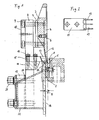
- Fig. 1 shows a cutter head for a meat cutting machine in side view in section.
- FIG. 2 shows in plan view a transverse knife segment for the cutter head of FIG. 1.
- a cutting material support with a counter-blade 1 and a Abstützkamm 2 Vertically movable up and down a cutter head is arranged, which is shown in the figure in its lowermost position at the end of the cutting stroke.
- the cutter head comprises a cutter bar 3, on which an in essentially over the width of the cutter head extending, vertically arranged upper blade 4, the cutting edge 5 forms the bottom thereof, is secured by screws 6.
- a stop bracket 8 is fastened by means of screws 9, optionally, with the interposition of a spacer plate 7, the head of which is covered by a cover plate 10.
- the stop bracket 8 comprises a horizontal cross member 11, which extends approximately over the length of the upper blade 4.
- the upper blade 4 is bevelled on its side facing away from the cutting material support side towards the blade 5 and there provided with equidistant mutually arranged grooves 12.
- the grooves 12 each serve to guide a transverse knife 13 with a cutting edge 14.
- Several transverse knives 13, for example three transverse knives 13, are combined with web portions located therebetween to form a one-piece segment 15.
- the segments 15 are fastened next to each other on the crossbar 11 by means of screws 16 releasably.
- a passage 17 is formed for a meat strip cut off by two adjacent transverse blades 13 from a slice of meat separated by the upper blade 4 (or, if a slice of meat is used, for the cubes formed).
- the cutting thickness E for the meat strips or cubes is determined by the distance of a vertical stop plate 18 of the Schneidgutauflage, which is arranged below the segments 15 of the transverse blade 13.
- the stop plate 18 has on both sides in each case a tab 19, with which it is screwed by screws 20 with the stop bracket 8.
- one or more spacer plates 21 can be arranged between the stop bracket 8 and lugs 19.
- stop plate 18 on the side facing away from the Schneidgutauflage an extending over the entire width, top obliquely, approximately U-shaped plate 22 carries, on which the lateral tabs 19 are attached.
Landscapes
- Life Sciences & Earth Sciences (AREA)
- Forests & Forestry (AREA)
- Engineering & Computer Science (AREA)
- Mechanical Engineering (AREA)
- Knives (AREA)
- Details Of Cutting Devices (AREA)
- Processing Of Meat And Fish (AREA)
- Meat, Egg Or Seafood Products (AREA)
- Food-Manufacturing Devices (AREA)
Description
- Die Erfindung betrifft einen Messerkopf für eine Fleischschneidemaschine nach dem Oberbegriff des Anspruchs 1.
- Aus EP 0 192 039 B1 ist ein Messerkopf dieser Art bekannt, bei dem ein Obermesser vorgesehen ist, das eine unterseitige Schneide zum Zusammenwirken mit einer Schneidgutauflage als Gegenmesser aufweist. Ferner ist eine Vielzahl von Quermessern vorgesehen, deren quer zur Schneide des Obermessers schneidende Schneiden auf der der Schneidgutauflage abgewandten Seite des Obermessers in Nuten hiervon geführt angeordnet und auf einer Traverse befestigt sind. Hierbei ist jedes Quermesser mittels Schrauben befestigt, wobei eine Vielzahl von Nuten, Spalten und Schrauben nur aufwendig zu säubern ist, wobei zugleich der fertigungstechnische Aufwand groß ist, abgesehen davon, daß zur Verstellung der Schneiddicke alle Quermesser in ihrer Lage zum Obermesser neu eingestellt werden müssen.
- Aufgabe der Erfindung ist es, einen Messerkopf für eine Fleischschneidemaschine nach dem Oberbegriff des Anspruchs 1 zu schaffen, der konstruktiv einfacher und leichter zu säubern ist.
- Diese Aufgabe wird entsprechend dem kennzeichnenden Teil des Anspruchs 1 gelöst.
- Dadurch, daß jeweils mehrere Quermesser mit Zwischenstegen zu einem einstückigen Segment zusammengefaßt sind, wobei die Segmente nebeneinander auf der Traverse lösbar befestigt sind, wird nicht nur die Konstruktion vereinfacht, sondern es werden auch die Nuten, Spalten und Schrauben in ihrer Zahl verringert und das Säubern dementsprechend erleicht.
- Außerdem erlaubt es diese Konstruktion, die Schneiddicke in einfacher Weise zu ändern, indem die Traverse feststehend am Messerkopf befestigt ist und eine sich über die Schneidbreite erstreckende, vertikale Anschlagplatte unterhalb der Quermesser in Bezug auf den Abstand zur Schneidgutauflage einstellbar ist. Hierbei ist es insbesondere zweckmäßig, wenn die Anschlagplatte unter Zwischenschaltung von einer oder mehreren Distanzplatten im Abstand zur Schneidgutauflage einstellbar ist.
- Weitere Ausgestaltungen der Erfindung sind der nachfolgenden Beschreibung und den Unteransprüchen zu entnehmen.
- Die Erfindung wird nachstehend anhand eines in der beigefügten Abbildung dargestellten Ausführungsbeispiels näher erläutert.
- Fig. 1 zeigt einen Messerkopf für eine Fleischschneidemaschine in Seitenansicht im Schnitt.
- Fig. 2 zeigt in Draufsicht ein Quermessersegment für den Messerkopf von Fig. 1.
- Die insgesamt nicht dargestellte Fleischschneidemaschine umfaßt gemäß Fig. 1 eine Schneidgutauflage mit einer Gegenschneide 1 und einem Abstützkamm 2. Vertikal auf- und abbeweglich ist hierzu ein Messerkopf angeordnet, der in der Abbildung in seiner untersten Stellung am Ende des Schneidhubs dargestellt ist.
- Der Messerkopf umfaßt einen Messerbalken 3, an dem ein sich im wesentlichen über die Breite des Messerkopfs erstreckendes, vertikal angeordnetes Obermesser 4, dessen Schneide 5 die Unterseite hiervon bildet, mittels Schrauben 6 befestigt ist. An der dem Obermesser 4 abgewandten Seite des Messerbalkens 3 ist gegebenenfalls unter Zwischenschaltung einer Distanzplatte 7 eine Anschlaghalterung 8 mittels Schrauben 9 befestigt, deren Kopf von einer Abdeckplatte 10 abgedeckt wird. Die Anschlaghalterung 8 umfaßt eine horizontale Traverse 11, die sich etwa über die Länge des Obermessers 4 erstreckt.
- Das Obermesser 4 ist auf seiner der Schneidgutauflage abgewandten Seiten zur Schneide 5 hin abgeschrägt und dort mit äquidistant zueinander angeordneten Nuten 12 versehen. Die Nuten 12 dienen jeweils zum Führen eines Quermessers 13 mit einer Schneide 14. Mehrere Quermesser 13, beispielsweise drei Quermesser 13, sind mit dazwischen befindlichen Stegbereichen zu einem einstückigen Segment 15 zusammengefaßt. Die Segmente 15 sind nebeneinander auf der Traverse 11 mittels Schrauben 16 lösbar befestigt. Zwischen den Stegbereichen und dem Obermesser 4 wird jeweils ein Durchtritt 17 für einen durch zwei benachbarte Quermesser 13 von einer durch das Obermesser 4 abgetrennten Fleischscheibe abgeschnittenen Fleischstreifen gebildet (bzw. wenn von einer Fleischscheibe ausgegangen wird, für die gebildeten Würfel).
- Die Schneiddicke E für die Fleischstreifen bzw. -würfel wird über den Abstand einer vertikalen Anschlagplatte 18 von der Schneidgutauflage vorgegeben, die unterhalb der Segmente 15 der Quermesser 13 angeordnet ist. Die Anschlagplatte 18 besitzt an beiden Seiten jeweils eine Lasche 19, mit der sie über Schrauben 20 mit der Anschlaghalterung 8 verschraubt ist. Um die Schneiddicke E zu verändern, können zwischen Anschlaghalterung 8 und Laschen 19 eine oder mehrere Distanzplatten 21 angeordnet werden.
- Ferner ist es zweckmäßig, wenn die Anschlagplatte 18 auf der der Schneidgutauflage abgewandten Seite ein sich über die gesamte Breite erstreckendes, oberseitig schräg verlaufendes, etwa U-förmiges Blech 22 trägt, an dem die seitlichen Laschen 19 befestigt sind.
- Beim Schneiden taucht das Obermesser 4, wie dargestellt, in einen kleinen V-förmigen Spalt zwischen der Gegenschneide 1 und dem Abstützkamm 2 ein, während die Quermesser 13 in Nuten des Abstützkamms 2 eintauchen.
Claims (6)
- Messerkopf für eine Fleischschneidemaschine mit einem Obermesser (4), das eine unterseitige Schneide (5) zum Zusammenwirken mit einer Schneidgutauflage als Gegenmesser aufweist, und einer Vielzahl von Quermessern (13) mit quer zur Schneide (5) des Obermessers (4) schneidenden Schneiden (14), wobei die Quermesser (13) auf der der Schneidgutauflage abgewandten Seite des Obermessers (4) in Nuten (12) hiervon geführt angeordnet und auf einer Traverse (11) befestigt sind, dadurch gekennzeichnet, daß jeweils mehrere Quermesser (13) mit dazwischen befindlichen Stegbereichen zu einem einstückigen Segment (15) zusammengefaßt sind, wobei die Segmente (15) nebeneinander auf der Traverse (11) lösbar befestigt sind.
- Messerkopf nach Anspruch 1, dadurch gekennzeichnet, daß die Segmente (15) an der Traverse (11) angeschraubt sind.
- Messerkopf nach Anspruch 1 oder 2, dadurch gekennzeichnet, daß die Traverse (11) feststehend am Messerkopf befestigt ist und eine sich über die Schneidbreite erstreckende, vertikale Anschlagplatte (18) unterhalb der Segmente (15) der Quermesser (13) in Bezug auf den Abstand zur Schneidgutauflage einstellbar ist.
- Messerkopf nach Anspruch 3, dadurch gekennzeichnet, daß die Anschlagplatte (18) unter Zwischenschaltung von einer oder mehreren Distanzplatten (21) im Abstand zur Schneidgutauflage einstellbar ist.
- Messerkopf nach Anspruch 3 oder 4, dadurch gekennzeichnet, daß die Anschlagplatte (18) seitliche Laschen (19) zum Verschrauben mit dem Messerkopf aufweist.
- Messerkopf nach Anspruch 5, dadurch gekennzeichnet, daß die Anschlagplatte (18) auf der der Schneidgutauflage abgewandten Seite ein sich über die gesamte Breite erstreckendes, oberseitig schräg verlaufendes Blech (22) trägt, an dem die seitlichen Laschen (19) befestigt sind.
Applications Claiming Priority (2)
| Application Number | Priority Date | Filing Date | Title |
|---|---|---|---|
| DE20204492U DE20204492U1 (de) | 2002-03-21 | 2002-03-21 | Messerkopf für eine Fleischschneidemaschine |
| DE20204492U | 2002-03-21 |
Publications (3)
| Publication Number | Publication Date |
|---|---|
| EP1346802A2 EP1346802A2 (de) | 2003-09-24 |
| EP1346802A3 EP1346802A3 (de) | 2004-12-29 |
| EP1346802B1 true EP1346802B1 (de) | 2006-07-26 |
Family
ID=27675239
Family Applications (1)
| Application Number | Title | Priority Date | Filing Date |
|---|---|---|---|
| EP03003967A Expired - Lifetime EP1346802B1 (de) | 2002-03-21 | 2003-02-22 | Messerkopf für eine Fleischschneidemaschine |
Country Status (4)
| Country | Link |
|---|---|
| EP (1) | EP1346802B1 (de) |
| AT (1) | ATE333968T1 (de) |
| DE (2) | DE20204492U1 (de) |
| ES (1) | ES2268179T3 (de) |
Cited By (3)
| Publication number | Priority date | Publication date | Assignee | Title |
|---|---|---|---|---|
| DE202011103095U1 (de) | 2011-07-12 | 2011-11-16 | Magurit Gefrierschneider Gmbh | Messerkopf für eine Produktschneidemaschine |
| DE102015000983A1 (de) | 2015-01-27 | 2016-08-11 | Magurit Gefrierschneider Gmbh | Messerkopf für eine Produktschneidemaschine |
| DE102024106924A1 (de) | 2024-03-11 | 2025-09-11 | Magurit Gefrierschneider Gmbh | Messerkopf für eine Produktschneidemaschine |
Family Cites Families (2)
| Publication number | Priority date | Publication date | Assignee | Title |
|---|---|---|---|---|
| CH271595A (de) * | 1949-04-29 | 1950-11-15 | Marx Christian | Von Hand betätigbare Zerkleinerungsvorrichtung für Früchte und Gemüse. |
| DE8505062U1 (de) * | 1985-02-22 | 1986-06-26 | MAGURIT Gefrierschneider GmbH, 5630 Remscheid | Messerkopf für eine Fleischschneidemaschine |
-
2002
- 2002-03-21 DE DE20204492U patent/DE20204492U1/de not_active Expired - Lifetime
-
2003
- 2003-02-22 EP EP03003967A patent/EP1346802B1/de not_active Expired - Lifetime
- 2003-02-22 AT AT03003967T patent/ATE333968T1/de active
- 2003-02-22 ES ES03003967T patent/ES2268179T3/es not_active Expired - Lifetime
- 2003-02-22 DE DE50304320T patent/DE50304320D1/de not_active Expired - Lifetime
Cited By (5)
| Publication number | Priority date | Publication date | Assignee | Title |
|---|---|---|---|---|
| DE202011103095U1 (de) | 2011-07-12 | 2011-11-16 | Magurit Gefrierschneider Gmbh | Messerkopf für eine Produktschneidemaschine |
| EP2546034A1 (de) | 2011-07-12 | 2013-01-16 | MAGURIT Gefrierschneider GmbH | Messerkopf für eine Produktschneidemaschine |
| DE102015000983A1 (de) | 2015-01-27 | 2016-08-11 | Magurit Gefrierschneider Gmbh | Messerkopf für eine Produktschneidemaschine |
| DE102015000983B4 (de) * | 2015-01-27 | 2020-02-20 | Magurit Gefrierschneider Gmbh | Messerkopf für eine Produktschneidemaschine |
| DE102024106924A1 (de) | 2024-03-11 | 2025-09-11 | Magurit Gefrierschneider Gmbh | Messerkopf für eine Produktschneidemaschine |
Also Published As
| Publication number | Publication date |
|---|---|
| EP1346802A2 (de) | 2003-09-24 |
| ATE333968T1 (de) | 2006-08-15 |
| DE20204492U1 (de) | 2003-07-31 |
| EP1346802A3 (de) | 2004-12-29 |
| DE50304320D1 (de) | 2006-09-07 |
| ES2268179T3 (es) | 2007-03-16 |
Similar Documents
| Publication | Publication Date | Title |
|---|---|---|
| EP0104267B1 (de) | Küchengerät zum Schneiden von Lebensmitteln | |
| EP2580032B1 (de) | Werkzeug zum nachschneiden von wischerblättern | |
| DE102007006754A1 (de) | Furnierschneidvorrichtung | |
| EP2370235B1 (de) | Küchenhobel | |
| DE202009009557U1 (de) | Hobel zum Schneiden von Obst, Gemüse oder ähnlichen Lebensmitteln | |
| DE102015000983B4 (de) | Messerkopf für eine Produktschneidemaschine | |
| EP1346802A2 (de) | Messerkopf für eine Fleischschneidemaschine | |
| DE10238260A1 (de) | Papierführungsaufbau einer Schredder-Vorrichtung | |
| EP2546034B1 (de) | Messerkopf für eine Produktschneidemaschine | |
| DE19523272C1 (de) | Küchengerät zum Schneiden von Gut, insbesondere Obst oder Gemüse | |
| DE3908220C2 (de) | ||
| DE19720753A1 (de) | Stanzwerkzeug | |
| DE10226987A1 (de) | Schneidemaschine für Lebensmittel, insbesondere für Braten | |
| DE9413852U1 (de) | Gemüseschneider | |
| DE29917640U1 (de) | Schneideeinrichtung für Weichkäse | |
| EP0192039B1 (de) | Messerkopf für eine Fleischschneidemaschine | |
| DE2605234B2 (de) | Messerkopf für eine Gefrierfleischschneidemaschine | |
| DE9306627U1 (de) | Küchenhobel, insbesondere zum Schneiden von Obst und Gemüse | |
| EP0247364B1 (de) | Messerkopf für eine Fleischschneidemaschine | |
| DE3020126C2 (de) | Messerhalter für ein hin- und hergehendes Messer eines Mähwerkes | |
| DE29911299U1 (de) | Messerkopf für eine Nahrungsmittelschneidemaschine | |
| EP2625334B1 (de) | Vorrichtung zum halten von schaberklingen | |
| DE6608205U (de) | Lebensmittelschneidegeraet. | |
| DE1582437A1 (de) | Maehwerk | |
| DE146545C (de) |
Legal Events
| Date | Code | Title | Description |
|---|---|---|---|
| PUAI | Public reference made under article 153(3) epc to a published international application that has entered the european phase |
Free format text: ORIGINAL CODE: 0009012 |
|
| AK | Designated contracting states |
Kind code of ref document: A2 Designated state(s): AT BE BG CH CY CZ DE DK EE ES FI FR GB GR HU IE IT LI LU MC NL PT SE SI SK TR |
|
| AX | Request for extension of the european patent |
Extension state: AL LT LV MK RO |
|
| PUAL | Search report despatched |
Free format text: ORIGINAL CODE: 0009013 |
|
| AK | Designated contracting states |
Kind code of ref document: A3 Designated state(s): AT BE BG CH CY CZ DE DK EE ES FI FR GB GR HU IE IT LI LU MC NL PT SE SI SK TR |
|
| AX | Request for extension of the european patent |
Extension state: AL LT LV MK RO |
|
| 17P | Request for examination filed |
Effective date: 20050211 |
|
| AKX | Designation fees paid |
Designated state(s): AT DE ES GB |
|
| GRAP | Despatch of communication of intention to grant a patent |
Free format text: ORIGINAL CODE: EPIDOSNIGR1 |
|
| GRAS | Grant fee paid |
Free format text: ORIGINAL CODE: EPIDOSNIGR3 |
|
| GRAA | (expected) grant |
Free format text: ORIGINAL CODE: 0009210 |
|
| AK | Designated contracting states |
Kind code of ref document: B1 Designated state(s): AT DE ES GB |
|
| REG | Reference to a national code |
Ref country code: GB Ref legal event code: FG4D Free format text: NOT ENGLISH |
|
| REF | Corresponds to: |
Ref document number: 50304320 Country of ref document: DE Date of ref document: 20060907 Kind code of ref document: P |
|
| GBT | Gb: translation of ep patent filed (gb section 77(6)(a)/1977) |
Effective date: 20061004 |
|
| REG | Reference to a national code |
Ref country code: ES Ref legal event code: FG2A Ref document number: 2268179 Country of ref document: ES Kind code of ref document: T3 |
|
| PLBE | No opposition filed within time limit |
Free format text: ORIGINAL CODE: 0009261 |
|
| STAA | Information on the status of an ep patent application or granted ep patent |
Free format text: STATUS: NO OPPOSITION FILED WITHIN TIME LIMIT |
|
| 26N | No opposition filed |
Effective date: 20070427 |
|
| PGFP | Annual fee paid to national office [announced via postgrant information from national office to epo] |
Ref country code: AT Payment date: 20200220 Year of fee payment: 18 Ref country code: ES Payment date: 20200322 Year of fee payment: 18 Ref country code: GB Payment date: 20200219 Year of fee payment: 18 |
|
| PGFP | Annual fee paid to national office [announced via postgrant information from national office to epo] |
Ref country code: DE Payment date: 20200427 Year of fee payment: 18 |
|
| REG | Reference to a national code |
Ref country code: DE Ref legal event code: R119 Ref document number: 50304320 Country of ref document: DE |
|
| REG | Reference to a national code |
Ref country code: AT Ref legal event code: MM01 Ref document number: 333968 Country of ref document: AT Kind code of ref document: T Effective date: 20210222 |
|
| GBPC | Gb: european patent ceased through non-payment of renewal fee |
Effective date: 20210222 |
|
| PG25 | Lapsed in a contracting state [announced via postgrant information from national office to epo] |
Ref country code: AT Free format text: LAPSE BECAUSE OF NON-PAYMENT OF DUE FEES Effective date: 20210222 |
|
| PG25 | Lapsed in a contracting state [announced via postgrant information from national office to epo] |
Ref country code: GB Free format text: LAPSE BECAUSE OF NON-PAYMENT OF DUE FEES Effective date: 20210222 Ref country code: DE Free format text: LAPSE BECAUSE OF NON-PAYMENT OF DUE FEES Effective date: 20210901 |
|
| REG | Reference to a national code |
Ref country code: ES Ref legal event code: FD2A Effective date: 20220513 |
|
| PG25 | Lapsed in a contracting state [announced via postgrant information from national office to epo] |
Ref country code: ES Free format text: LAPSE BECAUSE OF NON-PAYMENT OF DUE FEES Effective date: 20210223 |