EP1344751B1 - Verfahren und Vorrichtung für die Herstellung eines Tiegels aus Quarzglas mittels Lichtbogenschmelzen - Google Patents
Verfahren und Vorrichtung für die Herstellung eines Tiegels aus Quarzglas mittels Lichtbogenschmelzen Download PDFInfo
- Publication number
- EP1344751B1 EP1344751B1 EP03005353A EP03005353A EP1344751B1 EP 1344751 B1 EP1344751 B1 EP 1344751B1 EP 03005353 A EP03005353 A EP 03005353A EP 03005353 A EP03005353 A EP 03005353A EP 1344751 B1 EP1344751 B1 EP 1344751B1
- Authority
- EP
- European Patent Office
- Prior art keywords
- electrodes
- arc
- ring
- crucible
- alternating current
- Prior art date
- Legal status (The legal status is an assumption and is not a legal conclusion. Google has not performed a legal analysis and makes no representation as to the accuracy of the status listed.)
- Expired - Lifetime
Links
- VYPSYNLAJGMNEJ-UHFFFAOYSA-N Silicium dioxide Chemical compound O=[Si]=O VYPSYNLAJGMNEJ-UHFFFAOYSA-N 0.000 title claims description 70
- 238000000034 method Methods 0.000 title claims description 27
- 230000004927 fusion Effects 0.000 title description 4
- 239000000843 powder Substances 0.000 claims description 37
- 239000010453 quartz Substances 0.000 claims description 37
- 238000010438 heat treatment Methods 0.000 claims description 25
- 238000010891 electric arc Methods 0.000 claims description 9
- 238000004519 manufacturing process Methods 0.000 description 30
- 239000011521 glass Substances 0.000 description 9
- 239000013078 crystal Substances 0.000 description 8
- 230000018199 S phase Effects 0.000 description 5
- 238000011156 evaluation Methods 0.000 description 4
- 238000007751 thermal spraying Methods 0.000 description 4
- 230000000694 effects Effects 0.000 description 2
- 230000004048 modification Effects 0.000 description 2
- 238000012986 modification Methods 0.000 description 2
- 229910021421 monocrystalline silicon Inorganic materials 0.000 description 2
- 239000002245 particle Substances 0.000 description 2
- 230000002093 peripheral effect Effects 0.000 description 2
- 101100537937 Caenorhabditis elegans arc-1 gene Proteins 0.000 description 1
- 241000283907 Tragelaphus oryx Species 0.000 description 1
- 238000000151 deposition Methods 0.000 description 1
- 239000005350 fused silica glass Substances 0.000 description 1
- 239000002994 raw material Substances 0.000 description 1
Images


Classifications
-
- C—CHEMISTRY; METALLURGY
- C30—CRYSTAL GROWTH
- C30B—SINGLE-CRYSTAL GROWTH; UNIDIRECTIONAL SOLIDIFICATION OF EUTECTIC MATERIAL OR UNIDIRECTIONAL DEMIXING OF EUTECTOID MATERIAL; REFINING BY ZONE-MELTING OF MATERIAL; PRODUCTION OF A HOMOGENEOUS POLYCRYSTALLINE MATERIAL WITH DEFINED STRUCTURE; SINGLE CRYSTALS OR HOMOGENEOUS POLYCRYSTALLINE MATERIAL WITH DEFINED STRUCTURE; AFTER-TREATMENT OF SINGLE CRYSTALS OR A HOMOGENEOUS POLYCRYSTALLINE MATERIAL WITH DEFINED STRUCTURE; APPARATUS THEREFOR
- C30B35/00—Apparatus not otherwise provided for, specially adapted for the growth, production or after-treatment of single crystals or of a homogeneous polycrystalline material with defined structure
- C30B35/002—Crucibles or containers
-
- C—CHEMISTRY; METALLURGY
- C03—GLASS; MINERAL OR SLAG WOOL
- C03B—MANUFACTURE, SHAPING, OR SUPPLEMENTARY PROCESSES
- C03B19/00—Other methods of shaping glass
- C03B19/09—Other methods of shaping glass by fusing powdered glass in a shaping mould
- C03B19/095—Other methods of shaping glass by fusing powdered glass in a shaping mould by centrifuging, e.g. arc discharge in rotating mould
-
- C—CHEMISTRY; METALLURGY
- C30—CRYSTAL GROWTH
- C30B—SINGLE-CRYSTAL GROWTH; UNIDIRECTIONAL SOLIDIFICATION OF EUTECTIC MATERIAL OR UNIDIRECTIONAL DEMIXING OF EUTECTOID MATERIAL; REFINING BY ZONE-MELTING OF MATERIAL; PRODUCTION OF A HOMOGENEOUS POLYCRYSTALLINE MATERIAL WITH DEFINED STRUCTURE; SINGLE CRYSTALS OR HOMOGENEOUS POLYCRYSTALLINE MATERIAL WITH DEFINED STRUCTURE; AFTER-TREATMENT OF SINGLE CRYSTALS OR A HOMOGENEOUS POLYCRYSTALLINE MATERIAL WITH DEFINED STRUCTURE; APPARATUS THEREFOR
- C30B15/00—Single-crystal growth by pulling from a melt, e.g. Czochralski method
- C30B15/10—Crucibles or containers for supporting the melt
Definitions
- the present invention relates to a production process of a quartz glass crucible by a ring-like arc fusion, in which the process is suitable for the production of a crucible having a large open diameter, and also relates to a device for producing a quartz glass crucible.
- the production process of the quartz glass crucible according to a rotational mould method is the process, in which a quartz powder being stored in the inside of a rotational mould is heated to be fused by an arc discharge to produce the quartz glass crucible having the transparent layer at the inside and the opaque layer at the outside.
- a quartz powder being stored in the inside of a rotational mould is heated to be fused by an arc discharge to produce the quartz glass crucible having the transparent layer at the inside and the opaque layer at the outside.
- 3 electrodes are used, and the 3 phases alternating electric current flows to said 3 electrodes to form the arc (discharge) plasma between each of the electrodes.
- the electrode structure which can form the arc discharge having a large heating range, has been required.
- the conventional main electrode structure has 3 electrodes to 3 phases alternating current, and this structure has the fault that the arc becomes unstable to be cut off when a distance between the electrodes is increased in order to expand the heating range.
- the influence of air stream at the inside of the crucible by the rotation of the mould becomes large, so that the arc is cut off easily with the conventional electrode structure.
- the present invention mitigates against said conventional problems of the electrode structure in the production device of the quartz glass crucible, and provides the electrode structure required for forming a ring-like arc which is stable and has a large heating range, and is suitable to the production of a crucible having a large open diameter. Moreover the present invention provides the production process of the quartz glass crucible by using said electrode structure.
- a process for producing a quartz glass crucible wherein a quartz powder in a mould is heated to be fused by arc discharge from electrodes positioned around a rotational axis of the mould, to thereby produce the quartz glass crucible, said process comprising: using an electrode structure having 4 electrodes to 2 phases alternating current, 6 electrodes to 3 phases alternating current, 9 electrodes to 3 phases alternating current, or 8 electrodes to 4 phases alternating current, in which electrodes neighboring each other are positioned at regular intervals in a ring configuration; generating a stable ring-like arc around the ring between the electrodes neighboring each other without generating a continuous arc between electrodes facing each other across the central portion of the ring; and using the ring-like arc to heat a quartz powder to be fused to thereby produce the quartz glass crucible.
- the arc is formed between the electrodes neighboring each other, but not formed continuously between the electrodes facing each other across the central portion of the ring. Therefore, the central portion of the ring being encircled with the electrodes is not heated excessively, and it is possible to heat uniformly the inside of the crucible. Moreover, in order to expand the heating range, the distance between the electrodes neighboring each other can be increased within the range in which the arc discharge is possible, so that it is possible to expand easily the heating range, and to heat uniformly the crucible having a large open diameter.
- the above-described production process may be modified to further comprise using the electrode structure so as to have an absolute value ⁇ of a phase difference of alternating electric current between neighboring electrodes in the range of 90° ⁇ 180° to thereby generate the ring-like arc.
- the ring-like ark can be formed without forming the arc crossing at the central portion of the ring substantially, so that it is possible to heat uniformly without heating excessively the central portion of the crucible.
- the electrode structure having the above-described phase difference the electrode structures having 4 electrodes to 2 phases alternating current, 9 electrodes to 3 phases alternating current, and 8 electrodes to 4 phases alternating current, can be used.
- the above-described production process may also be modified to include the feature that the radius r of the circumference of said ring-like arc around the rotational axis of the mould is from 1 to % times the radius R of an open end of the crucible for at least a fixed time during heating.
- the suitable heating distance can be kept to the open diameter of the quartz glass crucible, and it is convenient for feeding the quartz powder to the mould by passing through the inside of the ring-like arc being encircled with the electrodes, and the side wall portion, the corner portion, and the bottom portion of the crucible can be heated uniformly.
- the production process may be modified to further comprise passing the quartz powder through the range being encircled with the ring-like arc for heating and fusing the quartz powder.
- the quartz powder layer being stored beforehand at the rotational mould is heated to be fused by the above-described ring-like arc while reducing the pressure, so that it is possible to change the circumference layer at the inside of the crucible to the transparent glass layer.
- an additional quartz powder is further dropped to pass through the inside of said ring-like arc plasma to be fused, and this fused quartz glass is deposited at the inside surface of the quartz glass crucible to make the quartz glass crucible having the transparent layer, i.e., it can be called a thermal spraying method.
- the production process of the present invention may include all of above-described modifications.
- a device for producing a quartz glass crucible by a rotational mould method comprising an electrode structure having 4 electrodes to 2 phases alternating current, 6 electrodes to 3 phases alternating current, 9 electrodes to 3 phases alternating current, or 8 electrodes to 4 phases alternating current, in which the electrodes neighboring each other are positioned at regular intervals in the ring configuration around a rotational axis of the mould, the device, in operation, generating a stable ring-like arc around the ring between the electrodes neighboring each other without generating a continuous arc between the electrodes facing each other across the central portion of the ring.
- the above production device may include the modification that the electrodes neighboring each other in the electrode structure are connected in the ring configuration so as, in operation of the device, to have an absolute value ⁇ of a phase difference of alternating electric current between neighbouring electrodes in the range of 90° ⁇ ⁇ ⁇ 180°.
- the central portion being encircled with the electrodes is not heated excessively, and the inside surface of the crucible is heated uniformly.
- the distance between the electrodes neighboring each other may be increased within the range being possible to make arc discharge, it is possible to heat uniformly the crucible having the large open diameter.
- the quartz glass crucible for pulling up single crystal silicon, wherein the bubble content of the transparent layer at the bottom portion is less than 0.03%, and the bubble content of the transparent layer at the side wall portion is less than 3 times of the bubble content of the transparent layer at the bottom portion.
- the production process of the present invention is a production process for a quartz glass crucible, in which a quartz powder in a mould is heated to be fused by arc discharge from electrodes, positioned around a rotational axis of the mould, to produce a quartz glass crucible.
- the process is also characterized by using an electrode structure in which electrodes neighboring each other are positioned at regular intervals in the ring configuration, to allow generation of a stable ring-like arc between the electrodes neighboring each other without generating a continuous arc between the electrodes facing each other across the central portion of the ring, and using the ring-like arc to heat a quartz powder to be fused.
- the device for carrying out the above-described production process of the present invention is characterised by having the electrode structure in which the electrodes neighboring each other are positioned at regular intervals in the ring configuration around the rotational axis of the mould, for forming the stable ring-like arc generated between the electrodes neighboring each other without generating a continuous arc between the electrodes facing each other across the central portion of the ring, for thereby heating the quartz powder in the mould.
- the present invention comprises the electrode structure, in which the electrodes neighboring each other are positioned at regular intervals in the ring configuration at around of the rotational axis of the mould, in order to heat uniformly the quartz powder in the mould without heating excessively the bottom portion of the quartzcrucible.
- the stable ring-like arc being generated between the electrodes neighboring each other is formed without forming the continuous arc between the electrodes facing each other across the central portion of the ring, so that the phase difference ⁇ (the absolute value) of the alternating electric currents between the electrodes neighboring each other becomes in the range of 90° ⁇ ⁇ ⁇ 180°.
- the phase difference ⁇ between the electrodes neighbouring each other is the absolute value.
- electrode structures having 4 electrodes to 2 phases alternating current, 6 electrodes to 3 phases alternating current, 9 electrodes to 3 phases alternating current or 8 electrodes to 4 phases alternating current can be used.
- each electrode is connected with a direct current, it is preferable that even electrodes are positioned in the ring configuration so as to become the electrodes neighboring each other having the different phases respectively.
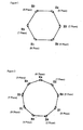
- FIG. 1 An example of one electrode structure used in accordance with the present invention is shown inFig. 1.
- the 6 electrodes (E1 to E6) are used to the 3 phases alternating electric current.
- the electrodes neighboring each other are positioned at regular intervals around the rotational axis of the crucible, and the hexagonal ring connecting each electrode is formed.
- the phase difference between the electrodes neighboring each other is 120°, and the electrodes facing each other across the central portion of the ring have the same phases as each other. More particularly, each electrode is connected as follows.
- the electrode E4 facing to the electrode E1 across the central portion of the ring has the same R phase when the electrode E1 has the R phase to the 3 phases alternating electric current, and at this time, the electrodes E2 and E6, which are both side of the electrode E1, have the T phase and the S phase respectively, and the electrodes E3 and E5, which are the peripheral side of the electrodes E2 and E6, have the S phase and the T phase respectively. Therefore, the electrodes E1 and E4, the electrodes E2 and E5, and the electrodes E3 and E6 have the same phases respectively, and have the different phases to the other electrodes respectively.
- the ring-like arc along with the inside surface of the crucible includes not only the arc being formed with the electrodes sticking out to the inside of the crucible but also the arc being formed in a concentric circle to the inner peripheral face of the crucible by the electrodes being positioned at the upper of the open of the crucible.
- Fig. 2 The example using the 9 electrodes (E1 to E9) to the 3 phases alternating electric current is shown in Fig. 2.
- the electrodes neighboring each other are positioned at around of the rotational axis so as to have the regular intervals each other, and a nonagonal ring connecting each electrode is formed.
- the phase difference between the electrodes neighboring each other is 120°to the 3 phases alternating electric current.
- the electrodes E2 and E9 which are both side of the electrode E1 have the T phase and the S phase respectively
- the electrodes E3 and E5, which are both side of the electrode E4 have the S phase and the T phase respectively
- the electrodes E6 and E8, which are both side of the electrode E7 have the S phase and the T phase respectively.
- the electrodes E2 and E9 which are closing to the electrode E1 have the phase difference to the electrode E1
- the stable arc can be formed between the electrode E1 and the electrodes E2 and E9.
- the electrodes E4 and E7 which are facing to the electrode E1 across the central portion of the ring-like arc, have the same phases as the electrode E1, the arc can not be formed between these electrodes.
- the electrodes E3 and E8, which are next closing to the electrode E1, and the electrodes E5 and E6, which are facing to the electrode E1 across the central portion of the ring-like arc have the phase difference to the electrode E1.
- the distances between the electrode Eland these electrodes E3, E8, E5, and E6 are larger than ones from the electrodes E2 and E9, if the arc is generated temporarily between these electrodes and the electrode E1, the arc can not be kept and the stable arc can not be formed.
- the arc crossing at the central portion being encircled with the electrodes can not be formed substantially, and the ring-like arc being generated between the electrodes neighboring each other can be formed.
- the ring-like arc being generated between the electrodes neighboring each other is formed like the above-description, and the stable arc crossing at the central portion of the ring is not formed substantially.
- Fig. 3 The example using the 4 electrodes (E1 to E4) to the 2 phases alternating electric current is shown in Fig. 3.
- the electrodes neighboring each other are positioned at regular intervals at around of the rotational axis of the mould to form the square ring connecting each electrode. Since the phase difference between the electrodes neighboring each other is 180°to the 2 phases alternating electric current, the arc is generated between the electrodes neighboring each other. However, since the electrodes facing each other across the central portion of the ring have the same phases each other, the arc is not generated between these electrodes, and the arc crossing at the central portion of the ring can not be formed.
- the ring-like arc being generated between the electrodes neighboring each other is formed like the above-description, and the stable arc crossing at the central portion of the ring is not formed substantially.
- Fig. 4 The example using the 8 electrodes (E1 to E8) to the 4 phases alternating electric current is shown in Fig. 4.
- the electrodes neighboring each other are positioned at regular intervals at around of the rotational axis of the mould to form the octagon ring connecting each electrode.
- the phase difference between the electrodes neighboring each other is 90°
- the phase difference between the electrodes, which are next closing to each other is 180°. Since the arc is generated mainly between the electrodes having the large phase difference, the arc is generated between the electrodes, which are next closing to each other, in this structure. So, the ring-like arc can be formed between the electrodes, which are next closing to each other.
- the ring-like arc being generated between the electrodes neighboring each other includes the ring-like arc being generated between the electrodes, which are next closing to each other.
- the electrodes facing each other across the central portion of the ring have the same phases each other, the arc is not formed between these electrodes.
- the distance between the electrodes is large, so that the arc is not kept. So, the stable arc can not be formed substantially.
- the arc is generated between the electrodes E1 and E4, the electrodes E2 and E5, and the electrodes E3 and E6, which are positioned by facing each other (at the diagonal line position), and is crossed at the central portion being encircled with from the electrode E2 to the electrode E6. Furthermore, in the conventional electrode structure, when the distance between the electrodes neighboring each other is increased, the distance between the electrodes facing each other becomes to be increased sharply, so the arc becomes unstable to be cut off easily.
- the electrode structure of the present invention since the ring-like arc being generated between the electrodes neighboring each other can be formed, when the distance between the electrodes is increased, it is difficult to cut off the arc and is possible to keep the stable arc.
- the radius r of the circumference S which is the circumference of the ring at around of the rotational axis, is from 1 to 1/4 to the radius R of the open of the crucible, at least for a fixed time at the time of arc heating. In this range, heating can be almost uniform from the side wall portion to corner portion and bottom portion of the crucible. Moreover, it is convenient for feeding the quartz powder to the mould to pass through the inside being encircled with the electrodes, in the thermal spraying method.
- the electrode can not be inserted into the inside of the crucible, so that the bottom portion of the crucible can not be heated sufficiently.
- the radius r of the circumference is smaller than 1/4 of the radius R of the open of the crucible, the side wall portion of the crucible can not be heated sufficiently, and when the quartz powder is fed by passing through the inside being encircled with the electrodes, it is difficult to feed the quartz powder since the passing range is narrow.
- the quartz glass crucible having the transparent layer at the inner periphery of the crucible and the opaque layer at the outer periphery, by heating the quartz powder being stored at the inner periphery face of the mould to be fused by the ring-like arc.
- the pressure of the quartz powder is reduced by evacuating from the mould side, and the air being contained in the quartz layer is removed by sucking to the outside. Then, the crucible having a little bubble content in the inside can be obtained.
- the rotational mould method it is possible to carry out the production process of the quartz glass crucible, in which the quartz powder is fed by passing through the range being encircled with the ring-like arc plasma to make glass particles being heated to be fused by the arc, and said glass particles are deposited at the inside surface of the mould to form the transparent layer, i.e., the thermal spraying method.
- the transparent glass layer can be formed at the bottom portion or all over the inner periphery face of the crucible.
- the arc can be formed mainly between the electrodes neighboring each other, the arc is stable and there is little air convection at the inside of the crucible. Therefore, when the quartz powder is fed by passing through the range being encircled with the ring-like arc, the quartz powder is not splashed to the outside by the convection, and all quartz powder can be fed to the mould substantially, so that almost all powder is not splashed to the outside or adhered to the electrodes. Therefore, the sufficient transparent layer can be formed at the bottom portion of the crucible or all over the crucible.
- the electrode structure forming the arc also between the electrodes facing each other such as the conventional electrode structure having the 3 electrodes to the 3 phases alternating current or the 6 electrodes to the 6 phases alternating current, there is large air convection near the central portion being encircled with the electrodes. Then, if the quartz powder is fed by passing through the central portion, the powders are splashed to the outside of the crucible, adhered to the electrodes, or fall down only partially, frequently. So, it is difficult to form a uniform transparent layer at the inner periphery face of the crucible.
- the above-described effect is remarkable especially.
- a big air stream is aroused at around of the crucible by an exhaust gas of a furnace or the convection at the inside of the crucible.
- the arc heating is carried out from the upper side of the mould, there are greatly influenced of said air stream. So, as shown in Example, the arc is cut off immediately with the 3 electrodes when the distance between the electrodes is increased.
- the structure having the 6 electrodes to the 3 phases alternating current when the arc heating is carried from the upper side of the mould, it is possible to obtain the stable arc.
- the production process or production device of the presentinvention it is possible to form the sufficient transparent glass layer by depositing the fused glass at the bottom portion of the crucible. More particularly, it is possible to obtain the transparent glass layer, for example, having the bubble content of less than 0.03%, preferably less than 0.01%. Moreover, even if the crucible has the large diameter, the bottom portion, corner portion, and side wall portion of the crucible can be heated to be fused sufficiently, so that it is possible to obtain the transparent layer at the corner portion or the side wall portion having a little bubble content.
- the quartz glass crucible having the open diameter of 32 inches was produced according to the rotational mould method.
- the process comprising, storing beforehand the quartz powder forming from the outer periphery layer to the inner periphery layer of the crucible in the rotational mould, using the electrode structures having the 6 electrodes to the 3 phases alternating current of the present invention, the conventional 3 electrodes to the 3 phases alternating current (Comparison example 1) and the conventional 6 electrodes to the 6 phases alternating current (Comparison example 2), changing the distance between the electrodes, and heating the quartz powder to be fused.
- Table 1 Table 1
- the expansion of the electrodes was 81mm
- the arc was cut off frequently, and the arc could not be generated when the diameter was increased more than 81mm.
- the electrode structure of Comparison example 2 although the arc could be generated sufficiently until the diameter of the circumference being positioned with the electrodes was 122mm, the arc became unstable when the diameter was increased to 405mm, and the arc was cut off frequently when the diameter was more than 405mm.
- the arc became unstable, and gave the bad influence for heating and fusing the quartz powder.
- Circumference Diameter (mm) Example (6 electrodes to 3 phases alternating current) Comparison 1 (3 electrodes to 3 phases alternating current) Comparison 2 (6 electrodes to 6 phases alternating current) 81(10%) Arc was stable and sufficient Arc was cut off frequently Arc was sufficient 122 (15 %) Arc was stable and sufficient Arc was not generated Arc was sufficient 162 (20 %) Arc was stable and sufficient Arc was not generated Arc was a little unstable 203 (25 %) Arc was stable and sufficient Arc was not generated Arc was unstable 243 (30 %) Arc was stable and sufficient Arc was not generated Arc was unstable 405 (50 %) Arc was stable and sufficient Arc was not generated Arc was unstable 567 (70 %) Arc was stable and sufficient Arc was not generated Arc was cut off frequently 810 (100 %) Arc was stable and sufficient Arc was not generated Arc was cut off frequently (Note) Circumference Diameter is a diameter of the circumference being positioned with the electrodes. % is a ratio of the circumference diameter
- the crucible having the open diameter of 32 inches was produced, using the electrode structure having the 6 electrodes to the 3 phases alternating current of the present invention, and changing the distance between the electrodes.
- the bubble content and the dislocation free ratio of the single crystal at pulling up the single crystal silicon were examined. These results were shown in Table 4.
- the crucibles in which the diameter of the circumference being positioned with the electrodes was too small to the diameter of the crucible (Samples of No.B1 and B2), since the side wall of the crucible was not heated sufficiently, the bubble content of this part was high.
- the crucible having the open diameter of 32 inches was produced by the thermal spraying method.
- the process comprising, using the electrode structures having the 6 electrodes to the 3 phases alternating current of the present invention and the conventional 3 electrodes to the 3 phases alternating current, storing the quartz powder forming the outer periphery layer and the intermediate layer at the inner circumference face of the mould, and feeding 4kg of the quartz powder to pass through the inside of the circumference while carrying out the arc fusion, to make 1mm of the transparent layer.
- the transparent layer thickness, bubble content, and dislocation free ratio of the single crystal of the crucible were examined. These results were shown in Table 5.
- the quartz powder was adhered to the electrodes when the quartz powder, which was raw material, was fed by passing through between the electrodes. So, it is difficult to form the transparent layer having the layer thickness of 1mm, and especially, the layer thickness of the side wall portion was thin sharply.
- the comparison samples of from No.B11 to B13 since the quartz block abraded from the electrodes fell down to the crucible and the irregularity at the inside circumference face of the crucible was made.
- the comparison samples of from No.B11 to B13 since the bubble content was high, the dislocation free ratio of the single crystal was low.
- a stable ring-like arc can be formed around the inner circumference of the mould to heat the quartz powder at the inner periphery of the mould to be fused. Therefore, it is possible to prevent that the heat at the bottom portion of the crucible becomes excessive, and to heat uniformly from the side wall to bottom portions. Then, it is possible to produce a quartz glass crucible having a sufficiently transparent layer. Moreover, since the arc is stable and the heating range is large, it is possible to obtain excellent quartz glass crucibles having large sized open diameters.
Landscapes
- Chemical & Material Sciences (AREA)
- Engineering & Computer Science (AREA)
- Materials Engineering (AREA)
- Organic Chemistry (AREA)
- Crystallography & Structural Chemistry (AREA)
- Metallurgy (AREA)
- Manufacturing & Machinery (AREA)
- Crystals, And After-Treatments Of Crystals (AREA)
- Glass Melting And Manufacturing (AREA)
Claims (6)
- Verfahren zur Herstellung eines Quarzglas-Tiegels, wobei ein Quarzpulver in einer Form so erhitzt wird, dass es durch eine Bogenentladung von Elektroden, die um eine Drehachse der Form positioniert sind, erhitzt wird, um hierdurch den Quarzglas-Tiegel zu erzeugen, gekennzeichnet durch:Verwendung einer Elektrodenstruktur, die vier Elektroden für einen Zweiphasen-Wechselstrom aufweist, sechs Elektroden für einen dreiphasigen Wechselstrom, neun Elektroden für einen dreiphasigen Wechselstrom, oder acht Elektroden für einen vierphasigen Wechselstrom, wobei Elektroden, die zueinander benachbart sind, in regelmäßigen Intervallen in einem Ringaufbau positioniert sind;Erzeugung eines stabilen ringförmigen Bogens um den Ring zwischen den zueinander benachbarten Elektroden ohne Erzeugen eines kontinuierlichen Bogens zwischen einander über den zentralen Abschnitt des Rings gegenüberstehenden Elektroden; undVerwendung des ringförmigen Bogens, um ein Quarzpulver zum Schmelzen zu erhitzen, um hierdurch den Quarzglas-Tiegel zu erzeugen.
- Verfahren gemäß Anspruch 1, des Weiteren umfassend die Verwendung der Elektrodenstruktur, um so einen absoluten Wert θ der Phasendifferenz des elektrischen Wechselstroms zwischen benachbarten Elektroden im Bereich von 90° ≤ θ ≤ 180° zu haben, um hierdurch den ringförmigen Bogen zu erzeugen.
- Verfahren gemäß Anspruch 1 oder Anspruch 2, wobei der Radius r des Umfangs des ringförmigen Bogens um die Drehachse der Form 1 bis ¼ mal dem Radius R eines offenen Endes des Tiegels für zumindest eine festgelegte Zeit während der Erhitzung entspricht.
- Verfahren gemäß Anspruch 1, 2 oder 3, des Weiteren umfassend das Hindurchtreten des Quarzpulvers durch den Bereich, der mit dem ringförmigen Bogen zur Erhitzung und zum Aufschmelzen des Quarzpulvers eingekreist ist.
- Vorrichtung zum Erzeugen eines Quarzglas-Tiegels mittels eines Drehform-Verfahrens, dadurch gekennzeichnet, dass sie eine Elektrodenstruktur umfasst, die vier Elektroden für zweiphasigen Wechselstrom, sechs Elektroden für dreiphasigen Wechselstrom, neun Elektroden für dreiphasigen Wechselstrom oder acht Elektroden für vierphasigen Wechselstrom aufweist, wobei die zueinander benachbarten Elektroden in regelmäßigen Intervallen in dem Ringaufbau um eine Drehachse der Form positioniert sind, die Vorrichtung im Betrieb einen stabilen ringförmigen Bogen um den Ring zwischen den zueinander benachbarten Elektroden ohne Erzeugung eines kontinuierlichen Bogens zwischen den einander über den zentralen Abschnitt des Rings gegenüberstehenden Elektroden zu erzeugen.
- Vorrichtung gemäß Anspruch 5, wobei die zueinander benachbarten Elektroden in dem Elektrodenaufbau in dem Ringaufbau so miteinander verbunden sind, dass sie beim Betrieb der Vorrichtung einen absoluten Wert θ einer Phasendifferenz des elektrischen Wechselstroms zwischen benachbarten Elektroden im Bereich von 90° ≤ θ ≤ 180° aufweisen.
Applications Claiming Priority (4)
| Application Number | Priority Date | Filing Date | Title |
|---|---|---|---|
| JP2002070903 | 2002-03-14 | ||
| JP2002070903 | 2002-03-14 | ||
| JP2003021195 | 2003-01-29 | ||
| JP2003021195A JP4300333B2 (ja) | 2002-03-14 | 2003-01-29 | リング状アークによる石英ガラスルツボの製造方法と装置およびその石英ガラスルツボ |
Publications (3)
| Publication Number | Publication Date |
|---|---|
| EP1344751A2 EP1344751A2 (de) | 2003-09-17 |
| EP1344751A3 EP1344751A3 (de) | 2004-08-11 |
| EP1344751B1 true EP1344751B1 (de) | 2007-06-13 |
Family
ID=27767236
Family Applications (1)
| Application Number | Title | Priority Date | Filing Date |
|---|---|---|---|
| EP03005353A Expired - Lifetime EP1344751B1 (de) | 2002-03-14 | 2003-03-12 | Verfahren und Vorrichtung für die Herstellung eines Tiegels aus Quarzglas mittels Lichtbogenschmelzen |
Country Status (5)
| Country | Link |
|---|---|
| US (1) | US6853673B2 (de) |
| EP (1) | EP1344751B1 (de) |
| JP (1) | JP4300333B2 (de) |
| CN (1) | CN100537465C (de) |
| DE (1) | DE60314311T2 (de) |
Families Citing this family (19)
| Publication number | Priority date | Publication date | Assignee | Title |
|---|---|---|---|---|
| DE10033632C1 (de) * | 2000-07-11 | 2002-01-03 | Heraeus Quarzglas | Vorrichtung zur Herstellung rotationssymmetrischer Quarzglastiegel |
| JP4300334B2 (ja) * | 2002-08-15 | 2009-07-22 | ジャパンスーパークォーツ株式会社 | 石英ガラスルツボの再生方法 |
| JP4995069B2 (ja) * | 2007-12-28 | 2012-08-08 | ジャパンスーパークォーツ株式会社 | 内面結晶化ルツボおよび該ルツボを用いた引上げ方法 |
| KR101176968B1 (ko) * | 2008-02-29 | 2012-08-30 | 쟈판 스파 쿼츠 가부시키가이샤 | 실리콘 단결정 인상용 석영 도가니 및 그 제조 방법 |
| JP5008695B2 (ja) * | 2008-06-30 | 2012-08-22 | ジャパンスーパークォーツ株式会社 | 石英ガラスルツボおよび石英ガラスルツボを用いたシリコン単結晶の引き上げ方法 |
| US20100000465A1 (en) * | 2008-07-07 | 2010-01-07 | Japan Super Quartz Corporation | Method for producing vitreous silica crucible |
| JP5142912B2 (ja) * | 2008-09-22 | 2013-02-13 | ジャパンスーパークォーツ株式会社 | アーク放電方法、アーク放電装置、石英ガラスルツボ製造装置 |
| JP2010076949A (ja) * | 2008-09-24 | 2010-04-08 | Japan Siper Quarts Corp | 石英ガラスルツボの製造方法と装置、および石英ガラスルツボ |
| JP5344423B2 (ja) | 2008-09-26 | 2013-11-20 | 株式会社Sumco | 炭素電極の製造方法および石英ガラスルツボの製造方法 |
| KR101154931B1 (ko) | 2009-01-08 | 2012-06-13 | 쟈판 스파 쿼츠 가부시키가이샤 | 석영 유리 도가니 제조 장치 |
| JP5388872B2 (ja) | 2009-01-14 | 2014-01-15 | 株式会社Sumco | 炭素電極研削装置 |
| EP3473602B1 (de) * | 2009-08-12 | 2019-11-13 | Japan Super Quartz Corporation | Vorrichtung zur herstellung eines quarzglastiegels und verfahren zur herstellung eines quarzglastiegels |
| CN102471926B (zh) * | 2009-09-09 | 2015-05-06 | 日本超精石英株式会社 | 复合坩埚及其制造方法以及硅晶体的制造方法 |
| FR2963341B1 (fr) * | 2010-07-27 | 2013-02-22 | Saint Gobain Quartz Sas | Creuset a ouverture polygonale |
| JP6104837B2 (ja) * | 2014-03-17 | 2017-03-29 | クアーズテック株式会社 | 石英ガラスルツボの製造方法 |
| WO2020056260A1 (en) | 2018-09-15 | 2020-03-19 | University Of South Florida | Arc melted glass piles for structural foundations |
| CN113727483B (zh) * | 2021-09-02 | 2022-12-20 | 合肥爱普利等离子体有限责任公司 | 一种多电极交流电弧放电装置、设备及交流电源 |
| CN114671599B (zh) * | 2022-03-29 | 2022-11-22 | 锦州佑鑫石英科技有限公司 | 大外径直拉单晶用石英坩埚的制备方法 |
| CN116321658A (zh) * | 2023-03-09 | 2023-06-23 | 常州大学 | 无需引弧装置的电弧等离子体系统以及起弧方法 |
Family Cites Families (17)
| Publication number | Priority date | Publication date | Assignee | Title |
|---|---|---|---|---|
| US234411A (en) * | 1880-11-16 | Ohaelbs e | ||
| US238236A (en) * | 1881-03-01 | Sleeping-car | ||
| US2089690A (en) * | 1934-12-24 | 1937-08-10 | Yngve R Cornelius | Electric furnace |
| US2993079A (en) * | 1957-04-15 | 1961-07-18 | Owens Illinois Glass Co | Electric heating method and apparatus for uniformly heating glass |
| US3520979A (en) * | 1968-02-26 | 1970-07-21 | Penelectro Ltd | Electrode circuit for hex electric furnace |
| US3997316A (en) * | 1976-01-19 | 1976-12-14 | Ppg Industries, Inc. | Use of crossed electrode pairs in a glassmaking furnace |
| US4911896A (en) * | 1986-07-24 | 1990-03-27 | General Electric Company | Fused quartz member for use in semiconductor manufacture |
| US4935046A (en) * | 1987-12-03 | 1990-06-19 | Shin-Etsu Handotai Company, Limited | Manufacture of a quartz glass vessel for the growth of single crystal semiconductor |
| JP2736969B2 (ja) | 1997-03-21 | 1998-04-08 | 三菱マテリアルクォーツ株式会社 | 石英ルツボ製造装置 |
| US6044667A (en) * | 1997-08-25 | 2000-04-04 | Guardian Fiberglass, Inc. | Glass melting apparatus and method |
| JPH11236233A (ja) * | 1998-02-23 | 1999-08-31 | Sumikin Sekiei Kk | 石英るつぼの製造方法 |
| JP4077952B2 (ja) * | 1998-09-04 | 2008-04-23 | コバレントマテリアル株式会社 | シリコン単結晶引上げ用石英ガラスルツボの製造方法 |
| US6143073A (en) * | 1998-11-19 | 2000-11-07 | Heraeus Shin-Etsu America | Methods and apparatus for minimizing white point defects in quartz glass crucibles |
| EP1094039B1 (de) * | 1999-04-06 | 2015-04-29 | Wacom Manufacturing Co., Ltd. | Verfahren zur herstellung eines quartzglastiegels |
| JP3647688B2 (ja) * | 1999-09-21 | 2005-05-18 | 東芝セラミックス株式会社 | 石英ガラスルツボ製造装置および製造方法 |
| DE10033632C1 (de) * | 2000-07-11 | 2002-01-03 | Heraeus Quarzglas | Vorrichtung zur Herstellung rotationssymmetrischer Quarzglastiegel |
| JP4300334B2 (ja) * | 2002-08-15 | 2009-07-22 | ジャパンスーパークォーツ株式会社 | 石英ガラスルツボの再生方法 |
-
2003
- 2003-01-29 JP JP2003021195A patent/JP4300333B2/ja not_active Expired - Fee Related
- 2003-03-10 US US10/383,608 patent/US6853673B2/en not_active Expired - Lifetime
- 2003-03-12 EP EP03005353A patent/EP1344751B1/de not_active Expired - Lifetime
- 2003-03-12 DE DE60314311T patent/DE60314311T2/de not_active Expired - Lifetime
- 2003-03-14 CN CNB031216641A patent/CN100537465C/zh not_active Expired - Fee Related
Also Published As
| Publication number | Publication date |
|---|---|
| EP1344751A2 (de) | 2003-09-17 |
| CN100537465C (zh) | 2009-09-09 |
| DE60314311T2 (de) | 2008-02-14 |
| DE60314311D1 (de) | 2007-07-26 |
| US20030210731A1 (en) | 2003-11-13 |
| EP1344751A3 (de) | 2004-08-11 |
| JP2003335532A (ja) | 2003-11-25 |
| JP4300333B2 (ja) | 2009-07-22 |
| US6853673B2 (en) | 2005-02-08 |
| CN1445184A (zh) | 2003-10-01 |
Similar Documents
| Publication | Publication Date | Title |
|---|---|---|
| EP1344751A2 (de) | Tiegel aus Quarzglas, sowie Verfahren und Vorrichtung für seine Herstellung mittels Lichtbogenschmelzen | |
| EP2168925A2 (de) | Verfahren und Vorrichtung zur Herstellung eines Quarzglastigels und der Quarzglastigel | |
| US4759787A (en) | Method of purifying molten silica | |
| EP2484813B1 (de) | Verbundtiegel, verfahren zu seiner herstellung und verwendung | |
| CN1443142A (zh) | 石英熔融炉和石英件的制造方法 | |
| JPH04325425A (ja) | 石英ガラスの製造方法、及びその製造装置 | |
| EP1391542B1 (de) | Reformierverfahren eines Quarzglastiegels | |
| US6143073A (en) | Methods and apparatus for minimizing white point defects in quartz glass crucibles | |
| EP1024118A2 (de) | Glashafen mit grossem Diameter zum Ziehen von Silikon-Einzelkristallen | |
| EP1630248B1 (de) | Verfahren zur ausbildung von dünnem film | |
| JPH0692779A (ja) | 単結晶引き上げ用石英るつぼ | |
| EP2128098B1 (de) | Verfahren zur Herstellung eines Quarzglastiegels | |
| JP3983054B2 (ja) | シリコン単結晶引上げ用石英ガラスるつぼ及びその製造方法 | |
| JP2000159593A (ja) | 石英ガラスるつぼの製造方法 | |
| JP3433976B2 (ja) | ガラス溶融ルツボ | |
| JPH0834628A (ja) | 高純度石英ガラスルツボの製造方法 | |
| JP2709644B2 (ja) | シリコン単結晶製造用石英るつぼの製造方法 | |
| EP2141130A1 (de) | Verfahren zur Herstellung eines Quarzglastiegels | |
| JPH07300327A (ja) | 透明石英ガラス層付不透明石英ガラス部材の製造方法 | |
| JP7612258B2 (ja) | 大外径チョクラルスキー単結晶用石英ルツボの製造方法 | |
| JPS60215534A (ja) | 石英ガラス治具 | |
| EP2163529A1 (de) | Vorrichtung zur Herstellung eines Quarztiegels | |
| JP3875780B2 (ja) | 高純度粉体の製造方法 | |
| CN118422335A (zh) | 晶体与坩埚的分离方法、装置及应用 | |
| KR20240175602A (ko) | 산화티타늄 제조장치 및 이 장치를 이용한 산화티타늄 제조방법 |
Legal Events
| Date | Code | Title | Description |
|---|---|---|---|
| PUAI | Public reference made under article 153(3) epc to a published international application that has entered the european phase |
Free format text: ORIGINAL CODE: 0009012 |
|
| AK | Designated contracting states |
Kind code of ref document: A2 Designated state(s): AT BE BG CH CY CZ DE DK EE ES FI FR GB GR HU IE IT LI LU MC NL PT RO SE SI SK TR |
|
| AX | Request for extension of the european patent |
Extension state: AL LT LV MK |
|
| PUAL | Search report despatched |
Free format text: ORIGINAL CODE: 0009013 |
|
| AK | Designated contracting states |
Kind code of ref document: A3 Designated state(s): AT BE BG CH CY CZ DE DK EE ES FI FR GB GR HU IE IT LI LU MC NL PT RO SE SI SK TR |
|
| AX | Request for extension of the european patent |
Extension state: AL LT LV MK |
|
| 17P | Request for examination filed |
Effective date: 20040909 |
|
| 17Q | First examination report despatched |
Effective date: 20050208 |
|
| AKX | Designation fees paid |
Designated state(s): DE FR |
|
| RBV | Designated contracting states (corrected) |
Designated state(s): DE FR |
|
| GRAP | Despatch of communication of intention to grant a patent |
Free format text: ORIGINAL CODE: EPIDOSNIGR1 |
|
| RTI1 | Title (correction) |
Free format text: PROCESS AND APPARATUS FOR PRODUCING A QUARTZ GLASS CRUCIBLE BY ARC FUSION |
|
| GRAS | Grant fee paid |
Free format text: ORIGINAL CODE: EPIDOSNIGR3 |
|
| RAP1 | Party data changed (applicant data changed or rights of an application transferred) |
Owner name: JAPAN SUPER QUARTZ CORPORATION |
|
| GRAA | (expected) grant |
Free format text: ORIGINAL CODE: 0009210 |
|
| AK | Designated contracting states |
Kind code of ref document: B1 Designated state(s): DE FR |
|
| REF | Corresponds to: |
Ref document number: 60314311 Country of ref document: DE Date of ref document: 20070726 Kind code of ref document: P |
|
| ET | Fr: translation filed | ||
| PLBE | No opposition filed within time limit |
Free format text: ORIGINAL CODE: 0009261 |
|
| STAA | Information on the status of an ep patent application or granted ep patent |
Free format text: STATUS: NO OPPOSITION FILED WITHIN TIME LIMIT |
|
| 26N | No opposition filed |
Effective date: 20080314 |
|
| PGFP | Annual fee paid to national office [announced via postgrant information from national office to epo] |
Ref country code: FR Payment date: 20120403 Year of fee payment: 10 |
|
| REG | Reference to a national code |
Ref country code: FR Ref legal event code: ST Effective date: 20131129 |
|
| PG25 | Lapsed in a contracting state [announced via postgrant information from national office to epo] |
Ref country code: FR Free format text: LAPSE BECAUSE OF NON-PAYMENT OF DUE FEES Effective date: 20130402 |
|
| REG | Reference to a national code |
Ref country code: DE Ref legal event code: R081 Ref document number: 60314311 Country of ref document: DE Owner name: SUMCO CORPORATION, JP Free format text: FORMER OWNER: JAPAN SUPER QUARTZ CORP., AKITA-SHI, JP Ref country code: DE Ref legal event code: R082 Ref document number: 60314311 Country of ref document: DE Representative=s name: KRAUS & WEISERT PATENTANWAELTE PARTGMBB, DE |
|
| PGFP | Annual fee paid to national office [announced via postgrant information from national office to epo] |
Ref country code: DE Payment date: 20210319 Year of fee payment: 19 |
|
| REG | Reference to a national code |
Ref country code: DE Ref legal event code: R119 Ref document number: 60314311 Country of ref document: DE |
|
| PG25 | Lapsed in a contracting state [announced via postgrant information from national office to epo] |
Ref country code: DE Free format text: LAPSE BECAUSE OF NON-PAYMENT OF DUE FEES Effective date: 20221001 |