EP1342635B1 - Fahrbetriebsmittel, wie Sessel oder Kabine, für eine Seilbahn, mit Schwenkbewegungsdämpfer - Google Patents
Fahrbetriebsmittel, wie Sessel oder Kabine, für eine Seilbahn, mit Schwenkbewegungsdämpfer Download PDFInfo
- Publication number
- EP1342635B1 EP1342635B1 EP02450249A EP02450249A EP1342635B1 EP 1342635 B1 EP1342635 B1 EP 1342635B1 EP 02450249 A EP02450249 A EP 02450249A EP 02450249 A EP02450249 A EP 02450249A EP 1342635 B1 EP1342635 B1 EP 1342635B1
- Authority
- EP
- European Patent Office
- Prior art keywords
- pendulum
- chair
- operating unit
- movable operating
- car
- Prior art date
- Legal status (The legal status is an assumption and is not a legal conclusion. Google has not performed a legal analysis and makes no representation as to the accuracy of the status listed.)
- Expired - Lifetime
Links
- 238000009434 installation Methods 0.000 title claims description 3
- 230000010355 oscillation Effects 0.000 title 1
- 230000001154 acute effect Effects 0.000 claims abstract description 4
- 238000013016 damping Methods 0.000 claims description 16
- 230000005484 gravity Effects 0.000 claims description 3
- 239000000725 suspension Substances 0.000 claims 4
- 238000005096 rolling process Methods 0.000 description 3
- 230000000694 effects Effects 0.000 description 2
- 230000002238 attenuated effect Effects 0.000 description 1
- 230000001681 protective effect Effects 0.000 description 1
Images




Classifications
-
- B—PERFORMING OPERATIONS; TRANSPORTING
- B61—RAILWAYS
- B61B—RAILWAY SYSTEMS; EQUIPMENT THEREFOR NOT OTHERWISE PROVIDED FOR
- B61B12/00—Component parts, details or accessories not provided for in groups B61B7/00 - B61B11/00
- B61B12/04—Devices for damping vibrations
-
- F—MECHANICAL ENGINEERING; LIGHTING; HEATING; WEAPONS; BLASTING
- F16—ENGINEERING ELEMENTS AND UNITS; GENERAL MEASURES FOR PRODUCING AND MAINTAINING EFFECTIVE FUNCTIONING OF MACHINES OR INSTALLATIONS; THERMAL INSULATION IN GENERAL
- F16F—SPRINGS; SHOCK-ABSORBERS; MEANS FOR DAMPING VIBRATION
- F16F15/00—Suppression of vibrations in systems; Means or arrangements for avoiding or reducing out-of-balance forces, e.g. due to motion
- F16F15/02—Suppression of vibrations of non-rotating, e.g. reciprocating systems; Suppression of vibrations of rotating systems by use of members not moving with the rotating systems
-
- F—MECHANICAL ENGINEERING; LIGHTING; HEATING; WEAPONS; BLASTING
- F16—ENGINEERING ELEMENTS AND UNITS; GENERAL MEASURES FOR PRODUCING AND MAINTAINING EFFECTIVE FUNCTIONING OF MACHINES OR INSTALLATIONS; THERMAL INSULATION IN GENERAL
- F16F—SPRINGS; SHOCK-ABSORBERS; MEANS FOR DAMPING VIBRATION
- F16F15/00—Suppression of vibrations in systems; Means or arrangements for avoiding or reducing out-of-balance forces, e.g. due to motion
- F16F15/28—Counterweights, i.e. additional weights counterbalancing inertia forces induced by the reciprocating movement of masses in the system, e.g. of pistons attached to an engine crankshaft; Attaching or mounting same
-
- F—MECHANICAL ENGINEERING; LIGHTING; HEATING; WEAPONS; BLASTING
- F16—ENGINEERING ELEMENTS AND UNITS; GENERAL MEASURES FOR PRODUCING AND MAINTAINING EFFECTIVE FUNCTIONING OF MACHINES OR INSTALLATIONS; THERMAL INSULATION IN GENERAL
- F16F—SPRINGS; SHOCK-ABSORBERS; MEANS FOR DAMPING VIBRATION
- F16F7/00—Vibration-dampers; Shock-absorbers
- F16F7/10—Vibration-dampers; Shock-absorbers using inertia effect
Definitions
- the subject invention relates to driving equipment for a cable car system with a chair or with a cabin, which or which at the bottom End of a support rod is attached, wherein at the upper end of the support rod a Clamping device for clamping the chair or cabin to a support or hoisting rope and optionally a drive are arranged and wherein Furthermore, the chair or the cabin is formed with a pendulum.
- pivoting movements the driving resources In the operation of cable car installations, there is the requirement of pivoting movements the driving resources largely excluded.
- pivoting movements the driving equipment in the direction of travel are limited by the fact that the between the support rods and the driving means provided joints are formed with damping devices, by which pivoting the driving equipment in the direction of travel limited to allowable dimensions become.
- pivoting movements of the driving resources therefore not limited transverse to the direction of travel by damping devices be, because through them the support and hoisting rope is twisted in itself and this Twist can not be prevented. It is important to take into account that by acting on the driving means wind forces simultaneously a A plurality of driving means are pivoted in the same direction, causing large forces to act on the support and hoisting rope.
- the driving means are formed with guides, in which rolling elements are movable. As soon as the driving equipment in one Swing out direction, the rolling elements move in the guides in the other direction, whereby the pivoting movements of the driving resources be significantly reduced.
- this known device is in their constructive design very expensive.
- the guides provide Such components are the inertia of the driving equipment enlarge, whereby the damping mass formed by the rolling body accordingly must be increased.
- a cable car system in which the driving resources are each formed with a pendulum, through which Pivoting movements of the driving means across the direction of travel prevented or to be reduced.
- the driving resources on the one hand and the associated pendulum on the other hand the same Have vibration frequencies.
- the pendulum formed much shorter than the pivot arms of the driving resources are the driving resources on the one hand and the pendulums on the other with significantly different frequencies, causing vibrations the driving means transverse to the direction of travel only in an insufficient Extent be dampened.
- the subject invention is therefore based on the object, a driving resources to create for a cable car plant, through which a substantial Damping of the vibrations of the driving equipment transverse to the direction of travel is effected.
- a support for the pendulum at the free end of which Bearing of the pendulum is located.
- the bearing for the pendulum located on the roof of the cabin.
- the pendulum is with a damping device formed, in particular, the bearing of the pendulum with a damping device is formed. Furthermore, the pendulum one Damping device be assigned in the form of an eddy current brake.
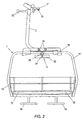
- the chair 1 of a cable car system shown in Figures 1 to 3 is at the bottom End of a support rod 2 articulated, at the upper end of a clamping device 21 and a drive 22 are provided.
- the clamping device 21 By means of the clamping device 21, the support rod 2 can be clamped to a support and hoisting cable 10.
- the Armchair 1 has a support frame 11, on which seat surfaces 12 for several Persons are attached. It is also equipped with a swiveling closing bar 13 formed, which is provided with footrests 14.
- the Armchair 1 may be formed with a pivotable protective hood.
- the support frame 11 is by means of a joint formed with a damping device 15 slightly pivoted on the support rod 2 in the conveying direction attached. This embodiment of the chair 1 is known from the prior art.
- this chair 1 is also formed with a pendulum 3, which is formed by a arranged on a pendulum rod 31 pendulum body 32 and which is in a bearing 33 which is provided on a bracket 34 attached to the bracket 2, is mounted.
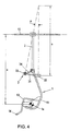
- the bearing axis of the pendulum 3 is approximately in the aligned in the conveying direction plane of symmetry of the chair 1, wherein it forms an acute angle ⁇ with the vertical body passing through the pendulum body 32.
- the center of gravity 1a of the chair 1 is at a distance a from the carrying and conveying cable 10.
- the virtual pivot axis of the pendulum 3, which is located at the intersection of the pivot axis of the pendulum 3 with the vertical by the pendulum body 32 in its middle position, from the pendulum body 32 also at a distance a, which distance for the action of the pendulum 3 authoritative is.
- the chair 1 and on the other hand the pendulum 3 form two pendulums, which swing around parallel axes, whereby the pendulum lengths effective for these two pendulums are equal.
- the pendulum 3 performs a pivoting of the chair 1 opposite pivoting, whereby the pivotal movement of the chair 1 is largely attenuated to the support and hoisting cable 10.
- the pendulum body 32 is associated with an eddy current brake 4, which are formed by permanent magnets 41, which are arranged on a bracket 42 attached to the support frame 2 or console 42.
- the pendulum 3 is associated with a pneumatic damping device 5, which is formed by a pneumatic cylinder 51 whose piston rod 52 is articulated to the pendulum rod 31, the cylinder 51 by means of a bracket 53 attached to the support frame 11 is.
- the pendulum is under Effect of tension springs 61, which on the one hand on the pendulum 3 and on the other the support rod 2 are articulated.
Landscapes
- Engineering & Computer Science (AREA)
- General Engineering & Computer Science (AREA)
- Mechanical Engineering (AREA)
- Physics & Mathematics (AREA)
- Acoustics & Sound (AREA)
- Aviation & Aerospace Engineering (AREA)
- Transportation (AREA)
- Vibration Prevention Devices (AREA)
- Storing, Repeated Paying-Out, And Re-Storing Of Elongated Articles (AREA)
- Handcart (AREA)
- Flexible Shafts (AREA)
Description
- Fig. 1
- einen Sessel einer Seilbahnanlage, welcher mit einem erfindungsgemäßen Pendel ausgebildet ist, in Seitenansicht;
- Fig.2
- den Sessel gemäß Fig. 1, in Vorderansicht;
- Fig.3
- den Sessel gemäß Fig. 1, in Draufsicht;
- Fig.4
- einen Sessel einer Seilbahnanlage mit einem Pendel, in schematischer Seitenansicht;
- Fig.5 bis 7
- den Sessel einer Seilbahnanlage, dessen Pendel mit unterschiedlichen Dämpfungseinrichtungen ausgebildet ist, jeweils in Draufsicht.
Durch das Pendel 3 erfolgt bei einer Schwenkbewegung des Sessels 1 quer zum Seil 10 eine gegenläufige Schwenkbewegung des Pendelkörpers 32, wodurch die Schwenkbewegung des Sessels 1 weitestgehend herabgesetzt wird.
Um die Wirkung des Pendels 3 einstellen zu können, besteht das Erfordernis, dessen Schwenkbewegungen zu dämpfen. Gemäß der in den Fig.5 und 5a dargestellten ersten Ausführungsform ist dem Pendelkörper 32 eine Wirbelstrombremse 4 zugeordnet, welche durch Permanentmagneten 41 gebildet sind, welche auf einer an der Tragstange 2 oder am Traggestell 11 befestigten Konsole 42 angeordnet sind.
Gemäß der in Fig.6 dargestellten Ausführungsform ist dem Pendel 3 eine pneumatische Dämpfungseinrichtung 5 zugeordnet, welche durch einen pneumatischen Zylinder 51, deren Kolbenstange 52 an die Pendelstange 31 angelenkt ist, gebildet ist, wobei der Zylinder 51 mittels einer Konsole 53 am Traggestell 11 befestigt ist.
Claims (6)
- Fahrbetriebsmittel für eine Seilbahnanlage mit einem Sessel (1) bzw. mit einer Kabine, welcher bzw. welche am unteren Ende einer Tragstange (2) befestigt ist, wobei am oberen Ende der Tragstange (2) eine Klemmeinrichtung zur Anklemmung des Sessels (1) bzw. der Kabine an ein Trag- bzw. Förderseil (10) und gegebenenfalls ein Laufwerk (22) angeordnet sind und wobei weiters der Sessel (1) bzw. die Kabine mit einem Pendel (3) ausgebildet ist, dadurch gekennzeichnet, dass das Pendel (3) um eine in der in Fahrtrichtung ausgerichteten vertikalen Symmetrieebene des Sessels (1) bzw. der Kabine liegenden, mit der Vertikalen einen spitzen Winkel (α) einschließende Achse gelagert ist und dass der Abstand (a) des Schwerpunktes (1a) des Sessels (1) bzw. der Kabine vom Trag- bzw. Förderseil (10) einerseits und der Abstand (a) der virtuellen Schwenkachse des Pendels (3), welche sich im Schnittpunkt der Schwenkachse des Pendels (3) mit der Vertikalen durch den Pendelkörper (32) in seiner mittleren Lage befindet, vom Pendelkörper (32) andererseits gleich groß sind.
- Fahrbetriebsmittel nach Patentanspruch 1, dadurch gekennzeichnet, dass an der Tragstange (2) bzw. an einem Traggestell (11) für das Fahrbetriebsmittel (1) ein Träger (34) für das Pendel (3) befestigt ist, an dessen freiem Ende sich das Pendellager (33) befindet.
- Fahrbetriebsmittel nach Patentanspruch 1, dadurch gekennzeichnet, dass sich das Lager für das Pendel am Dach der Kabine befindet.
- Fahrbetriebsmittel nach einem der Patentansprüche 1 bis 3, dadurch gekennzeichnet, dass das Pendel (3) mit einer Dämpfungseinrichtung, wie einer Federdämpfung (6) oder einer pneumatischen Dämpfungseinrichtung (5), ausgebildet ist.
- Fahrbetriebsmittel nach einem der Patentansprüche 1 bis 4, dadurch gekennzeichnet, dass das Pendellager (33) des Pendels (3) mit einer Dämpfungseinrichtung ausgebildet ist.
- Fahrbetriebsmittel nach einem der Patentansprüche 1 bis 4, dadurch gekennzeichnet, dass dem Pendelkörper (32) eine Dämpfungseinrichtung, z.B. eine Wirbelstrombremse (4), zugeordnet ist.
Priority Applications (1)
| Application Number | Priority Date | Filing Date | Title |
|---|---|---|---|
| AT02450249T ATE296737T1 (de) | 2002-03-07 | 2002-10-31 | Fahrbetriebsmittel, wie sessel oder kabine, für eine seilbahn, mit schwenkbewegungsdämpfer |
Applications Claiming Priority (2)
| Application Number | Priority Date | Filing Date | Title |
|---|---|---|---|
| AT3612002 | 2002-03-07 | ||
| AT3612002 | 2002-03-07 |
Publications (2)
| Publication Number | Publication Date |
|---|---|
| EP1342635A1 EP1342635A1 (de) | 2003-09-10 |
| EP1342635B1 true EP1342635B1 (de) | 2005-06-01 |
Family
ID=27739933
Family Applications (1)
| Application Number | Title | Priority Date | Filing Date |
|---|---|---|---|
| EP02450249A Expired - Lifetime EP1342635B1 (de) | 2002-03-07 | 2002-10-31 | Fahrbetriebsmittel, wie Sessel oder Kabine, für eine Seilbahn, mit Schwenkbewegungsdämpfer |
Country Status (4)
| Country | Link |
|---|---|
| EP (1) | EP1342635B1 (de) |
| AT (1) | ATE296737T1 (de) |
| DE (1) | DE50203267D1 (de) |
| ES (1) | ES2239706T3 (de) |
Families Citing this family (3)
| Publication number | Priority date | Publication date | Assignee | Title |
|---|---|---|---|---|
| ITMI20071556A1 (it) * | 2007-07-30 | 2009-01-31 | Rolic Invest Sarl | Unita' di trasporto per impianto di trasporto a fune e impianto di trasporto a fune comprendente tale unita' di trasporto |
| JP6856246B2 (ja) * | 2017-05-29 | 2021-04-07 | 日本ケーブル株式会社 | 索道の搬器 |
| CN117208022B (zh) * | 2023-09-19 | 2025-09-26 | 中煤能源研究院有限责任公司 | 适用于冲击地压矿井的防冲减震猴车 |
Family Cites Families (3)
| Publication number | Priority date | Publication date | Assignee | Title |
|---|---|---|---|---|
| AT395965B (de) * | 1990-10-10 | 1993-04-26 | Ssg Seilbahnbau Ges M B H | Gehaenge fuer ein kuppelbares fahrbetriebsmittel einer seilbahn |
| JP3064733B2 (ja) * | 1993-03-30 | 2000-07-12 | 寛 松久 | 振り子型構造物の動吸振器 |
| US6035787A (en) * | 1995-01-31 | 2000-03-14 | Ishikawajima Harima Heavy Industries, Co. | Vibration damping arrangement for cable car |
-
2002
- 2002-10-31 DE DE50203267T patent/DE50203267D1/de not_active Expired - Lifetime
- 2002-10-31 AT AT02450249T patent/ATE296737T1/de active
- 2002-10-31 EP EP02450249A patent/EP1342635B1/de not_active Expired - Lifetime
- 2002-10-31 ES ES02450249T patent/ES2239706T3/es not_active Expired - Lifetime
Also Published As
| Publication number | Publication date |
|---|---|
| DE50203267D1 (de) | 2005-07-07 |
| ATE296737T1 (de) | 2005-06-15 |
| ES2239706T3 (es) | 2005-10-01 |
| EP1342635A1 (de) | 2003-09-10 |
Similar Documents
| Publication | Publication Date | Title |
|---|---|---|
| EP3626322B1 (de) | Fahrzeug mit schwenk- und/oder drehbarer fahrgastaufnahme | |
| EP1640235B1 (de) | Einrichtung zur Befestigung eines Fahrbetriebsmittels einer Seilbahnanlage an einer Gehängestange | |
| DE9317132U1 (de) | Vorrichtung zur gefederten Führung eines Vorderrades am Rahmen eines Fahrrades | |
| EP1151903B1 (de) | Sessel für eine Seilbahnanlage | |
| EP0017856B1 (de) | Aufhängung für ein Fördermittel | |
| EP1086868A2 (de) | Doppelwirkende Rollenbatterie für Stützen von Einseilumlaufbahnen, insbesondere Sesselliften und Kabinenbahnen | |
| DE102011117805B4 (de) | Schwingungstilgung für das Spritzgestänge einer Feldspritze | |
| EP3354495A1 (de) | Mittelbügelsystem für ein mehrgliedriges fahrzeug | |
| DE3208680C2 (de) | ||
| DE2444887C3 (de) | Drehgestell für Schienenfahrzeuge | |
| DE497189C (de) | Verbindung des Wagenkastens mit dem Fahrzeugrahmen von Kraftfahrzeugen | |
| EP0327882A3 (de) | Seilförderanlage | |
| DE20018716U1 (de) | Vorrichtung zur Befestigung von Spritzgestängen an landwirtschaftlichen Fahrzeugen | |
| EP1342635A1 (de) | Fahrbetriebsmittel, wie Sessel oder Kabine, für eine Seilbahn, mit Schwenkbewegungsdämpfer | |
| AT402187B (de) | Vorrichtung zur befestigung einer kabine, eines sessels od.dgl. einer seilbahnanlage an einem gehänge | |
| DE2510100A1 (de) | Elastische daempfung einer stossstange | |
| DE1195795B (de) | Drehgestell fuer Schienenfahrzeuge mit luft-bereiften Laufraedern und seitlichen Fuehrungen | |
| DE1135310B (de) | Dynamischer Schwingungsdaempfer fuer eine Kraftfahrzeugradachse | |
| DE7018819U (de) | Vorrichtung zur stossdaempfung eines bootssitzes. | |
| DE3324574A1 (de) | Schlingerdaempfungsanordnung fuer drehgestell-schinenfahrzeuge | |
| DE102020003381A1 (de) | Gerät zur Fixierung und Führung von Kabeln an Seilwagen und Verfahren zur Anwendung dieses Geräts | |
| DE3409103C2 (de) | ||
| DE907726C (de) | Kettentrieb | |
| DE1018320B (de) | Anlenkung des unteren Teils von Teleskopstossdaempfern fuer Kraftfahrzeuge | |
| EP2974904B1 (de) | Oberleitungsanlage mit schwingungstilger |
Legal Events
| Date | Code | Title | Description |
|---|---|---|---|
| PUAI | Public reference made under article 153(3) epc to a published international application that has entered the european phase |
Free format text: ORIGINAL CODE: 0009012 |
|
| AK | Designated contracting states |
Kind code of ref document: A1 Designated state(s): AT BE BG CH CY CZ DE DK EE ES FI FR GB GR IE IT LI LU MC NL PT SE SK TR |
|
| AX | Request for extension of the european patent |
Extension state: AL LT LV MK RO SI |
|
| 17P | Request for examination filed |
Effective date: 20031127 |
|
| 17Q | First examination report despatched |
Effective date: 20040323 |
|
| AKX | Designation fees paid |
Designated state(s): AT BE BG CH CY CZ DE DK EE ES FI FR GB GR IE IT LI LU MC NL PT SE SK TR |
|
| GRAP | Despatch of communication of intention to grant a patent |
Free format text: ORIGINAL CODE: EPIDOSNIGR1 |
|
| GRAS | Grant fee paid |
Free format text: ORIGINAL CODE: EPIDOSNIGR3 |
|
| GRAA | (expected) grant |
Free format text: ORIGINAL CODE: 0009210 |
|
| AK | Designated contracting states |
Kind code of ref document: B1 Designated state(s): AT BE BG CH CY CZ DE DK EE ES FI FR GB GR IE IT LI LU MC NL PT SE SK TR |
|
| PG25 | Lapsed in a contracting state [announced via postgrant information from national office to epo] |
Ref country code: GB Free format text: LAPSE BECAUSE OF FAILURE TO SUBMIT A TRANSLATION OF THE DESCRIPTION OR TO PAY THE FEE WITHIN THE PRESCRIBED TIME-LIMIT Effective date: 20050601 Ref country code: FI Free format text: LAPSE BECAUSE OF FAILURE TO SUBMIT A TRANSLATION OF THE DESCRIPTION OR TO PAY THE FEE WITHIN THE PRESCRIBED TIME-LIMIT Effective date: 20050601 Ref country code: TR Free format text: LAPSE BECAUSE OF FAILURE TO SUBMIT A TRANSLATION OF THE DESCRIPTION OR TO PAY THE FEE WITHIN THE PRESCRIBED TIME-LIMIT Effective date: 20050601 Ref country code: CZ Free format text: LAPSE BECAUSE OF FAILURE TO SUBMIT A TRANSLATION OF THE DESCRIPTION OR TO PAY THE FEE WITHIN THE PRESCRIBED TIME-LIMIT Effective date: 20050601 Ref country code: EE Free format text: LAPSE BECAUSE OF FAILURE TO SUBMIT A TRANSLATION OF THE DESCRIPTION OR TO PAY THE FEE WITHIN THE PRESCRIBED TIME-LIMIT Effective date: 20050601 Ref country code: IE Free format text: LAPSE BECAUSE OF FAILURE TO SUBMIT A TRANSLATION OF THE DESCRIPTION OR TO PAY THE FEE WITHIN THE PRESCRIBED TIME-LIMIT Effective date: 20050601 Ref country code: NL Free format text: LAPSE BECAUSE OF FAILURE TO SUBMIT A TRANSLATION OF THE DESCRIPTION OR TO PAY THE FEE WITHIN THE PRESCRIBED TIME-LIMIT Effective date: 20050601 Ref country code: SK Free format text: LAPSE BECAUSE OF FAILURE TO SUBMIT A TRANSLATION OF THE DESCRIPTION OR TO PAY THE FEE WITHIN THE PRESCRIBED TIME-LIMIT Effective date: 20050601 |
|
| REG | Reference to a national code |
Ref country code: GB Ref legal event code: FG4D Free format text: NOT ENGLISH |
|
| REG | Reference to a national code |
Ref country code: CH Ref legal event code: EP Ref country code: CH Ref legal event code: NV Representative=s name: LUCHS & PARTNER PATENTANWAELTE |
|
| REF | Corresponds to: |
Ref document number: 50203267 Country of ref document: DE Date of ref document: 20050707 Kind code of ref document: P |
|
| REG | Reference to a national code |
Ref country code: IE Ref legal event code: FG4D Free format text: LANGUAGE OF EP DOCUMENT: GERMAN |
|
| PG25 | Lapsed in a contracting state [announced via postgrant information from national office to epo] |
Ref country code: GR Free format text: LAPSE BECAUSE OF FAILURE TO SUBMIT A TRANSLATION OF THE DESCRIPTION OR TO PAY THE FEE WITHIN THE PRESCRIBED TIME-LIMIT Effective date: 20050901 Ref country code: SE Free format text: LAPSE BECAUSE OF FAILURE TO SUBMIT A TRANSLATION OF THE DESCRIPTION OR TO PAY THE FEE WITHIN THE PRESCRIBED TIME-LIMIT Effective date: 20050901 Ref country code: DK Free format text: LAPSE BECAUSE OF FAILURE TO SUBMIT A TRANSLATION OF THE DESCRIPTION OR TO PAY THE FEE WITHIN THE PRESCRIBED TIME-LIMIT Effective date: 20050901 Ref country code: BG Free format text: LAPSE BECAUSE OF FAILURE TO SUBMIT A TRANSLATION OF THE DESCRIPTION OR TO PAY THE FEE WITHIN THE PRESCRIBED TIME-LIMIT Effective date: 20050901 |
|
| REG | Reference to a national code |
Ref country code: ES Ref legal event code: FG2A Ref document number: 2239706 Country of ref document: ES Kind code of ref document: T3 |
|
| PG25 | Lapsed in a contracting state [announced via postgrant information from national office to epo] |
Ref country code: CY Free format text: LAPSE BECAUSE OF FAILURE TO SUBMIT A TRANSLATION OF THE DESCRIPTION OR TO PAY THE FEE WITHIN THE PRESCRIBED TIME-LIMIT Effective date: 20051031 Ref country code: MC Free format text: LAPSE BECAUSE OF NON-PAYMENT OF DUE FEES Effective date: 20051031 Ref country code: LU Free format text: LAPSE BECAUSE OF NON-PAYMENT OF DUE FEES Effective date: 20051031 Ref country code: BE Free format text: LAPSE BECAUSE OF NON-PAYMENT OF DUE FEES Effective date: 20051031 |
|
| PG25 | Lapsed in a contracting state [announced via postgrant information from national office to epo] |
Ref country code: PT Free format text: LAPSE BECAUSE OF FAILURE TO SUBMIT A TRANSLATION OF THE DESCRIPTION OR TO PAY THE FEE WITHIN THE PRESCRIBED TIME-LIMIT Effective date: 20051107 |
|
| NLV1 | Nl: lapsed or annulled due to failure to fulfill the requirements of art. 29p and 29m of the patents act | ||
| GBV | Gb: ep patent (uk) treated as always having been void in accordance with gb section 77(7)/1977 [no translation filed] |
Effective date: 20050601 |
|
| REG | Reference to a national code |
Ref country code: IE Ref legal event code: FD4D |
|
| ET | Fr: translation filed | ||
| PLBE | No opposition filed within time limit |
Free format text: ORIGINAL CODE: 0009261 |
|
| STAA | Information on the status of an ep patent application or granted ep patent |
Free format text: STATUS: NO OPPOSITION FILED WITHIN TIME LIMIT |
|
| 26N | No opposition filed |
Effective date: 20060302 |
|
| BERE | Be: lapsed |
Owner name: INNOVA PATENT GMBH Effective date: 20051031 |
|
| REG | Reference to a national code |
Ref country code: FR Ref legal event code: PLFP Year of fee payment: 14 |
|
| REG | Reference to a national code |
Ref country code: FR Ref legal event code: PLFP Year of fee payment: 15 |
|
| REG | Reference to a national code |
Ref country code: FR Ref legal event code: PLFP Year of fee payment: 16 |
|
| REG | Reference to a national code |
Ref country code: FR Ref legal event code: PLFP Year of fee payment: 17 |
|
| PGFP | Annual fee paid to national office [announced via postgrant information from national office to epo] |
Ref country code: AT Payment date: 20181025 Year of fee payment: 17 |
|
| PGFP | Annual fee paid to national office [announced via postgrant information from national office to epo] |
Ref country code: CH Payment date: 20181025 Year of fee payment: 17 Ref country code: FR Payment date: 20181025 Year of fee payment: 17 Ref country code: ES Payment date: 20181127 Year of fee payment: 17 Ref country code: IT Payment date: 20181024 Year of fee payment: 17 |
|
| PGFP | Annual fee paid to national office [announced via postgrant information from national office to epo] |
Ref country code: DE Payment date: 20181228 Year of fee payment: 17 |
|
| REG | Reference to a national code |
Ref country code: DE Ref legal event code: R119 Ref document number: 50203267 Country of ref document: DE |
|
| REG | Reference to a national code |
Ref country code: CH Ref legal event code: PL |
|
| PG25 | Lapsed in a contracting state [announced via postgrant information from national office to epo] |
Ref country code: DE Free format text: LAPSE BECAUSE OF NON-PAYMENT OF DUE FEES Effective date: 20200501 Ref country code: LI Free format text: LAPSE BECAUSE OF NON-PAYMENT OF DUE FEES Effective date: 20191031 Ref country code: CH Free format text: LAPSE BECAUSE OF NON-PAYMENT OF DUE FEES Effective date: 20191031 |
|
| REG | Reference to a national code |
Ref country code: AT Ref legal event code: MM01 Ref document number: 296737 Country of ref document: AT Kind code of ref document: T Effective date: 20191031 |
|
| PG25 | Lapsed in a contracting state [announced via postgrant information from national office to epo] |
Ref country code: IT Free format text: LAPSE BECAUSE OF NON-PAYMENT OF DUE FEES Effective date: 20191031 Ref country code: FR Free format text: LAPSE BECAUSE OF NON-PAYMENT OF DUE FEES Effective date: 20191031 |
|
| PG25 | Lapsed in a contracting state [announced via postgrant information from national office to epo] |
Ref country code: AT Free format text: LAPSE BECAUSE OF NON-PAYMENT OF DUE FEES Effective date: 20191031 |
|
| REG | Reference to a national code |
Ref country code: ES Ref legal event code: FD2A Effective date: 20210414 |
|
| PG25 | Lapsed in a contracting state [announced via postgrant information from national office to epo] |
Ref country code: ES Free format text: LAPSE BECAUSE OF NON-PAYMENT OF DUE FEES Effective date: 20191101 |