EP1341399A2 - Verfahren und System zur Schallfeldsteuerung - Google Patents
Verfahren und System zur Schallfeldsteuerung Download PDFInfo
- Publication number
- EP1341399A2 EP1341399A2 EP02258805A EP02258805A EP1341399A2 EP 1341399 A2 EP1341399 A2 EP 1341399A2 EP 02258805 A EP02258805 A EP 02258805A EP 02258805 A EP02258805 A EP 02258805A EP 1341399 A2 EP1341399 A2 EP 1341399A2
- Authority
- EP
- European Patent Office
- Prior art keywords
- sound
- sound field
- reverberation characteristics
- reverberation
- frequency band
- Prior art date
- Legal status (The legal status is an assumption and is not a legal conclusion. Google has not performed a legal analysis and makes no representation as to the accuracy of the status listed.)
- Granted
Links
Images


Classifications
-
- H—ELECTRICITY
- H04—ELECTRIC COMMUNICATION TECHNIQUE
- H04M—TELEPHONIC COMMUNICATION
- H04M9/00—Arrangements for interconnection not involving centralised switching
- H04M9/08—Two-way loud-speaking telephone systems with means for conditioning the signal, e.g. for suppressing echoes for one or both directions of traffic
- H04M9/082—Two-way loud-speaking telephone systems with means for conditioning the signal, e.g. for suppressing echoes for one or both directions of traffic using echo cancellers
-
- H—ELECTRICITY
- H04—ELECTRIC COMMUNICATION TECHNIQUE
- H04S—STEREOPHONIC SYSTEMS
- H04S7/00—Indicating arrangements; Control arrangements, e.g. balance control
- H04S7/30—Control circuits for electronic adaptation of the sound field
- H04S7/305—Electronic adaptation of stereophonic audio signals to reverberation of the listening space
Definitions
- the present invention relates to a sound field control method and a sound field control system for obtaining reproduction sound with full realism by adding predetermined reverberation to the reproduction sound in sound reproduction in a reproduction sound field.
- trans-aural system is a system for attempting to obtain realism similar to that of the case listening in target sound space by listening to sound recorded in both of ear portions of a dummy head placed in a position corresponding to a position of a listener in target sound space in a reproduction sound field.
- This provides sound information similar to that on a recorded sound field for a listener by matching sound pressures PL, PR of respective external auditory meatus entrances of both of right and left ears of the dummy head in the case of recording with sound pressures SL, SR of respective external auditory meatus entrances of both of right and left ears of the listener in the reproduction sound field.
- a reproduction equivalent filter called a crosstalk cancel filter and control of the reproduction sound field is performed.
- a signal processing apparatus called a reverberation addition apparatus.
- this has an initial reflected sound generation part with a finite length in a front stage of a system and adds its output signal to a reproduction sound source in a reverberation generation part of aback stage.
- filters of IIR (Infinite Impulse Response) type like a comb filter are arranged in parallel is generally used as the reverberation generation part.
- IIR Infinite Impulse Response
- a purpose is to strictly control localization, reverberation and sound quality of an original sound field, so that an optimal solution of a filter for canceling characteristics of the reproduction sound field did not necessarily become stable and also when there is a big difference between characteristics of the original sound field and the reproduction sound field, an uncomfortable feeling might remain acoustically.
- realism in the original sound field can be obtained in the case of listening in an optimal position, but even in the case of listening in a position slightly deviating from its point, it became realism quite different from that in the original sound field and a narrow control area became a problem.
- sound addition information that is, phase, amplitude, reverberation characteristics, etc. were determined and provided uniquely based on know-how of a designer without consideration of characteristics of the reproduction sound field. Because of that, the addition information did not always match with each the reproduction sound field, and also in a form in which sound field data of the reproduction sound field is convolved directly with the reproduction sound source, a long filter was required and it became a large-scale system configuration.
- an object of the invention is to provide a method and a system for obtaining reproduction sound with realism similar to that of an original sound field regardless of listening positions by adding sound information to respective reproduction sound fields in correspondence with specific characteristics.
- a sound field control method of the invention comprises the steps of measuring reverberation characteristics of a first sound field used as the reference, measuring reverberation characteristics of a second sound field for listening, detecting a difference between the reverberation characteristics of the first sound field and the reverberation characteristics of the second sound field measured, calculating information added to a sound source offered to listening in the second sound field based on the difference between the reverberation characteristics detected, and adding the calculated information to the sound source.
- the sound field control method of the invention is a method of control capable of obtaining realism similar to that of wide listening space also in, for example, narrow listening space in the case of listening to sound.
- a first sound field used as the reference.. is, for example, a recording studio or a music hall, and a second sound field corresponds to a room of a listener or the inside of a car.
- reverberation characteristics of listening space act greatly and the reverberation characteristics of narrow space attenuate faster than those of wide space and when listening to sound recorded in the wide space in the narrow space, an uncomfortable feeling is given.
- the invention is constructed so that realism similar to that of the case of listening in the first sound field can be obtained by measuring the reverberation characteristics in the first sound field and the reverberation characteristics in the second sound field and detecting a difference between the two reverberation characteristics and obtaining information added to a sound source reproduced in the second sound field based on its difference and adding the information to original sound in the case of reproduction.
- Sound waves arriving at a listener include direct sound from a speaker and reflected sound which reflects on a wall, a ceiling, a floor, furniture, etc. of a room and arrives with delay from the direct sound, and the reverberation characteristics are characteristics related to this reflected sound.
- Reverberation of a wide room is maintained for a long time than reverberation of a narrow room. Therefore, a reflected sound pattern is obtained so as to approximate to the reverberation characteristics in the first sound field from the reverberation characteristics in the first sound field and the reverberation characteristics in the second sound field and is added to the original sound in the case of reproduction.
- the first sound field may be set in various state depending on purpose, and a listener can listen in a sound field approximated to environment set.
- a sound field control method of the invention comprises the steps of dividing a sound source offered to listening into predetermined frequency bands, measuring reverberation characteristics of a first sound field used as the reference every the divided frequency band, measuring reverberation characteristics of a second sound field for listening every the divided frequency band, detecting a difference between the reverberation characteristics of the first sound field and the reverberation characteristics of the second sound field measured every the divided frequency band, calculating information added to a sound source offered to listening in the second sound field based on the difference between the reverberation characteristics detected every the divided frequency band, adding the calculated information every the frequency band to the sound source, and combining the sound source to which the information is added every the frequency band.
- the sound field control method of the invention is a method of control in which a sound source is divided into predetermined frequency bands and the most effective reflected sound pattern is obtained in the respective frequency bands and is added to the sound source every the frequency band and further all are combined to produce an output in the case of obtaining the reflected sound pattern so as to approximate to the reverberation characteristics in the first sound field as described above from the reverberation characteristics in the first sound field and the reverberation characteristics in the second sound field.
- the reverberation characteristics of a high frequency component attenuate rapidly as compared with those of a low frequency component. Therefore, more effective realism can be obtained by obtaining the optimum reflected sound pattern every the frequency band and adding the reflected sound pattern to the sound source.
- the information added to the sound source is reflected sound information.
- the reflected sound pattern is obtained so that the reverberation characteristics in the second sound field approximate to the reverberation characteristics in the first sound field as described above from the reverberation characteristics in the first sound field and the reverberation characteristics in the second sound field.
- measurement of the reverberation characteristics is made by driving a speaker by a predetermined signal and collecting a sound wave issued from the speaker by a microphone placed in a predetermined position and analyzing an impulse response between the speaker and the microphone from the predetermined signal and sound information collected by the microphone.
- a predetermined signal is inputted to a speaker and a sound wave is generated from the speaker and its sound wave is collected by a microphone. It can be obtained analyzing an impulse response between the speaker and the microphone from the inputted predetermined signal and a signal collected by the microphone.
- the microphone is placed in a position corresponding to the head of a listener.
- a measurement result is recorded on recording means and is used as data in the case of obtaining a reflected sound pattern.
- an input signal for example, an impulse signal, M-sequence noise, a time stretched pulse, etc. are used.
- the reverberation characteristics in the respective frequency bands may be obtained using a burst signal with a limited band.
- measurement of the reverberation characteristics and calculation of information added to the sound source are made with respect to plural speakers.
- the reverberation characteristics in the first sound field and the second sound field are measured individually with respect to each of the speakers arranged in predetermined places.
- a sound field control system of the invention comprises means for measuring reverberation characteristics of a first sound field used as the reference, means for measuring reverberation characteristics of a second sound field for listening, means for detecting a difference between the reverberation characteristics of the first sound field and the reverberation characteristics of the second sound field measured, means for calculating information added to a sound source offered to listening in the second sound field based on the difference between the reverberation characteristics detected, and means for adding the calculated information to the sound source.
- the sound field control system of the invention is a system for performing control so that realism similar to that of wide listening space can be obtained also in, for example, narrow listening space in the case of listening to sound.
- Means for measuring reverberation characteristics of a first sound field and means for measuring reverberation characteristics of a second sound field are means for measuring the reverberation characteristics in the respective sound fields, and the same configurations are used in the configuration. When a different configuration is used, it is necessary to correct measurement standards between their means.
- Means for detecting a difference between the reverberation characteristics detects its difference from measurement results of the reverberation characteristics in the first sound field and the reverberation characteristics in the second sound field.
- Means for calculating information added to a sound source obtains the information added to the sound source reproduced in the second sound field, namely a reflected sound pattern from the difference between the two reverberation characteristics.
- means for adding information adds its information to original sound in the case of reproducing the original sound in the second sound field.
- a sound field control system of the invention comprises means for dividing a sound source offered to listening into predetermined frequency bands, means for measuring reverberation characteristics of a first sound field used as the reference every the divided frequency band, means for measuring reverberation characteristics of a second sound field for listening every the divided frequency band, means for detecting a difference between the reverberation characteristics of the first sound field and the reverberation characteristics of the second sound field measured every the divided frequency band, means for calculating information added to a sound source offered to listening in the second sound field based on the difference between the reverberation characteristics detected every the divided frequency band, means for adding the calculated information every the frequency band to the sound source, and means for combining the sound source to which the information is added every the frequency band.
- the sound field control system of the invention is a system of a configuration in which a sound source is divided into predetermined frequency bands and the most effective reflected sound pattern is obtained in the respective frequency bands and is added to the sound source every the frequency band and further all are combined to produce an output in the case of obtaining the reflected sound pattern so as to approximate to the reverberation characteristics in the first sound field as described above from the reverberation characteristics in the first sound field and the reverberation characteristics in the second sound field.
- Means for making a division into frequency bands divides the frequency bands by a predetermined band width in order to obtain information added to the sound source every the predetermined frequency band in the case of reproduction in the second sound field from the reverberation characteristics in the first sound field and the reverberation characteristics in the second sound field.
- means for measuring the reverberation characteristics of the first sound field and means for measuring the reverberation characteristics of the second sound field are means for measuring the reverberation characteristics in the respective sound fields, and the same configurations are used in the configuration. When a different configuration is used, it is necessary to correct measurement standards between their means.
- Means for detecting a difference between the reverberation characteristics detects its difference from measurement results of the reverberation characteristics every the frequency band in the first sound field and the second sound. field.
- Means for calculating information added to a sound source obtains the information added to the sound source reproduced in the second sound field, namely a reflected sound pattern every the frequency band from the difference between the two reverberation characteristics.
- means for adding information adds its information to original sound every the frequency band in the case of reproducing the original sound in the second sound field.
- means for combining the sound source combines the sound source to which the reflected sound pattern is added every these frequency bands and produces an output.
- a sound field control system of the invention there is provided means for adjusting a gain every the divided frequency band.
- a level can be adjusted every the divided frequency band, so that frequency characteristics can be adjusted easily.
- a sound field control system of the invention is constructed using a filter having a transfer function matching with a transfer function between input and output of a signal instead of the means for dividing the frequency bands, the means for adding the information to the sound source, the means for adjusting the gain and the means for combining the sound source.
- the means for adding the information to the sound source and the means for adjusting the gain is constructed using a filter having a transfer function matching with a transfer function between input and output of a signal through each of these means.
- the means for dividing the frequency bands, the means for adding the information to the sound source and the means for adjusting the gain are constructed by a filter having a transfer function matching with a transfer function between input and output of a signal. Adjustment can be made every the divided band.
- the means for measuring the reverberation characteristics comprises a speaker, generation means of a predetermined signal inputted to said speaker, a microphone for collecting a sound wave issued from the speaker, and means for analyzing an impulse response between the speaker and the microphone from the predetermined signal and sound information collected by the microphone.
- a predetermined signal is inputted to a speaker and a sound wave for reverberation characteristic measurement is issued from the speaker.
- a microphone collects the sound wave issued from the speaker, and means for analyzing sound information analyzes an impulse response between the speaker and the microphone from the predetermined signal and the sound wave collected by the microphone and obtains the reverberation characteristics. Further, the obtained reverberation characteristics are recorded on a recorder as data for generating a reflected sound pattern added in the second sound field.
- the reverberation characteristics relate to characteristics of, for example, sound reflected and transmitted in a wall, a ceiling, a floor, etc. of a sound field in addition to direct sound of the case that sound issued from a speaker is transmitted to a listener in a sound field at the time of listening to music, and have an influence on realism of the listener.
- a specific feature is had by a width of the sound field or a frequency band.
- Fig. 1 is a diagram showing a measuring system for measuring reverberation characteristics of a sound field in a sound field control method and a sound field control system of the invention
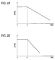
- Figs. 2A and 2B are graphs showing the measured reverberation characteristics
- Fig. 2A is one example of the reverberation characteristics in a wide sound field
- Fig. 2B is one example of the reverberation characteristics in a narrow sound field
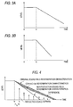
- Figs. 3A and 3B are graphs showing the reverberation characteristics
- Fig. 3A is one example of the reverberation characteristics at a low frequency
- Fig. 3B is one example of the reverberation characteristics at a high frequency.
- the measuring system of the reverberation characteristics is constructed by comprising, for example, a speaker 2 for issuing signal sound for measurement, a microphone 3 provided in a position at a predetermined distance from the speaker 2, a test signal generator 4 for generating a signal for driving the speaker 2, an amplifier 5 for driving the speaker 2, an amplifier 6 for adjusting a level of sound received by the microphone 3, an analyzer 7 for obtaining the reverberation characteristics by analyzing an impulse response from a signal of the test signal generator 4 and a sound wave signal collected by the microphone 3, and a recorder 8 for recording the obtained reverberation characteristics in a sound field 1. Further, it may comprise control means such as a personal computer for controlling the system.
- a signal from the test signal generator 4 for example, an impulse signal, M-sequence noise, a time stretched pulse, etc. is adjusted to a predetermined level by the amplifier 5 and its output is inputted to the speaker 2 and driving is performed and a sound wave is generated inside the sound field 1.
- the sound wave issued inside the sound field 1 is collected by the microphone 3.
- the microphone 3 is placed in the front of the speaker 2 in a position corresponding to the head of the case that a listener listens to music.
- Sounds from the speaker 2 include a sound arriving at the microphone 3 directly as shown by numeral L1 and a sound arriving at it after reflecting on a wall, a ceiling, a floor, etc. of the sound field 1 as shown by numerals L2, L3, and these show a feature of reverberation sound.
- a signal of the sound wave collected by the microphone 3 is changed to a predetermined level by the amplifier 6 and is inputted to the analyzer 7 and the reverberation characteristics are measured.
- the obtained reverberation characteristics are recorded on the recorder 8 and are used as data of comparison with other sound field or correction of the reverberation characteristics.
- reverberation characteristics are measured individually with respect to the respective speakers and the reverberation characteristics corresponding to the respective speakers are corrected at the time of reproducing.
- a personal computer equipped with a measuring program may be used instead of the analyzer 7 or the recorder 8. Also, this personal computer may be offered to control of the whole measuring system.
- Fig. 2A is one example of the reverberation characteristics in a wide sound field 1
- Fig. 2B is one example of the reverberation characteristics in a narrow sound field 1
- a range to time to is an energy integral value of a total of direct sound and reflected sound arriving at the microphone 3 and a range after time to is an energy integral value by the reflected sound.
- the narrow sound field 1 attenuation of the energy integral value by the reflected sound is fast as compared with the wide sound field 1.
- Fig. 3A is one example of the reverberation characteristics at a low frequency
- Fig. 3B is one example of the reverberation characteristics at a high frequency
- a range to time to is an energy integral value of a total of direct sound and reflected sound arriving at the microphone 3 and a range after time to is an energy integral value by the reflected sound.
- at the high frequency attenuation of the energy integral value by the reflected sound is fast as compared with the low frequency.
- the reverberation characteristics vary depending on conditions of .the sound field for reproducing sound or frequency bands, and realism by effect of the reflected sound varies depending on environment in which a listener listens to music. Therefore, the invention is designed so that based on these factors, information about the reflected sound is added to reproduction sound according to the reverberation characteristics of a reproduction sound field and the reproduction sound close to ideal realism of an original sound field is obtained.
- Fig. 4 is a diagram showing correction of reverberation characteristics of a sound field
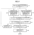
- Fig. 5 is a flowchart showing a flow of generation of a reflected sound pattern added
- Fig. 6 is a flowchart showing a flow of calculation of reverberation characteristics every band
- Fig. 7 is a flowchart showing a flow of a generation subroutine in generation of the reflected sound pattern shown in Fig. 5.
- reverberation attenuates in a short time as compared with original sound field reverberation characteristics.
- a first reflected sound pattern is added at time te after a lapse of predetermined time tc from time to at which direct sound has arrived and sequentially, reflected sound patterns every frequency band are added.
- a level of the reflected sound pattern is determined so that a difference between the reproduction sound field reverberation characteristics and the original sound field reverberation characteristics becomes smaller than a predetermined value.
- a flow of generation of the reflected sound pattern will be described.
- an impulse response h 0 in an original sound field is measured. This is measured in a sound field such as a music hall in which desired realism can be obtained by the system shown in Fig. 1 (step 101) .
- reverberation characteristics every frequency band in its sound field are calculated (step 102). This calculation will be described below with reference to Fig. 6.
- reverberation characteristics R 0 every band (M) obtained are recorded and are offered to generation of the reflected sound pattern of step 108 (step 103).
- an impulse response h 1 in a reproduction sound field is measured (step 104) .
- This is also measured in a sound field reproduced by the system shown in Fig. 1.
- the number of bands is divided into M bands in a manner similar to that of the original sound field, and initialization for obtaining a reflected sound pattern about the first band is performed (step 105) .
- a center frequency is divided into nine bands of 63, 125, 250, 500, 1 k, 2 k, 4 k, 8 k, 16 kHz.
- a coefficient of a band-pass filter of the i -th band is set to B (step 106), and convolution calculation of the impulse response of the reproduction sound field and the band-pass filter is performed (step 107).
- a reflected sound pattern C is obtained from the impulse response h 0 of the original sound field obtained previously (step 108) . Calculation of this reflected sound pattern will be described below with reference to Fig. 7.
- step 109 it is set to the next band (step 109), and it is determined whether or not calculation of the reflected sound pattern has been performed with respect to all the bands (step 110) and when there is still the band to be calculated, the flow returns to step 106 and a reflected sound pattern about the next band is calculated.
- step 111 when the reflected sound patterns are obtained with respect to all the bands (step 111), the flow is ended.
- a frequency band is divided into M bands, and calculation is set to the first band (step 202).
- a coefficient of a band-pass filter is set to B (step 203) , and convolution calculation of an impulse response of an original sound field and the band-pass filter is performed (step 204).
- reverberation attenuation characteristics are calculated using a reverberation integral expression proposed by Schroeder which is generally called "Schroeder's reverberation integral expression" (step 205).
- step 206 it is set to the next band (step 206), and it is determined whether or not calculation of the reverberation attenuation characteristics has been performed with respect to all the bands (step 207) and when there is still the band to be calculated, the flow returns to step 203 and reverberation attenuation characteristics about the next band are calculated.
- step 208 corresponds to step 103.
- an initial state of a reflected sound pattern is set (step 301).
- reverberation characteristics of a reproduction sound field are calculated (step 302), and a difference between an original sound field and the reproduction sound field in the reverberation characteristics is calculated (step 303).
- a sum of the differences in the reverberation characteristics in all the bands of the original sound field and the reproduction sound field is set to Ers (step 304). It is determined whether or not this Ers is smaller than a reference difference th set (step 305) and when it is smaller, generation of the reflected sound pattern is ended.
- time te at which the maximum value of the amount of error is taken is calculated (step 306), and time at which a result of convolution calculation of an impulse response of the reproduction sound field and a band-pass filter becomes maximum is subtracted from the time te and it is set to time tc (step 307) , and a reflected sound pattern Ci is set at this time tc (step 308). Further, a random number is added to the reflected sound pattern Ci (step 309) , and attenuation characteristics of a band i are calculated by a reverberation integral expression of Schroeder (step 310).
- step 311 a difference in the attenuation characteristics in a frequency band i of the original sound field and the reproduction sound field is obtained (step 311). These differences are sequentially summed (step 312), and it is determined whether or not its value is smaller than an error obtained in step 304 (step 313) . When it is not smaller, the flow returns to step 308, and the following calculation is performed similarly using a random number newly generated in step 309. When it is smaller, the error minimum value and the reflected sound pattern Ci are set and the flow returns to step 305 and it is again determined whether or not the error minimum value is smaller than a set value. When it is smaller, calculation of the reflected sound pattern is ended and according to the flowchart of Fig. 5, the reflected sound pattern of each the frequency band is decided and is superimposed on the reproduction sound.
- a generation method of the reflected sound pattern is not limited to the method described above. As long as there is a method capable of obtaining the reflected sound pattern to be added to the reproduction sound from a difference between the original sound field and the reproduction sound field in the reverberation characteristics, any method can also be used.
- Steps of the sound field control method of the embodiment comprise an original sound field reverberation characteristic measuring step 11, a reproduction sound field reverberation characteristic measuring step 12, a reverberation difference detection step 13, an addition information calculation step 14, and an information addition step 15.
- the original sound field reverberation characteristic measuring step 11 is a step of measuring reverberation characteristics of an original sound field, and is a step of inputting a signal for measurement, for example, an impulse signal to a speaker and outputting the signal as a sound wave and collecting its sound wave by a microphone placed in a predetermined position of the front of the speaker and analyzing the collected signal by an analyzer as described with reference to Fig. 1.
- the microphone is set in a position corresponding to the head of the case that a listener listens.
- a recording studio or a music hall can be assumed. Also, it can be set to a sound field of listener's pleasure.
- the impulse signal includes all the frequency components in principle, and transfer functions of transfer paths of the sound wave including characteristics of the speaker and the microphone can be measured at once.
- the transfer paths of the sound wave there are direct sound from the speaker to the microphone and reflected sound which is reflected and transmitted in a wall, a ceiling, a floor, furniture, etc. of a sound field, and these form reverberation characteristics specific to the sound field.
- the measured reverberation characteristics are recorded on a recorder, and are compared with reverberation characteristics of a reproduction sound field, and it is offered to calculation of addition information to reproduction sound, namely a reflected sound pattern.
- M-sequence noise or a time stretched pulse can be used instead of the impulse signal.
- the reproduction sound field reverberation characteristic measuring step 12 measures reverberation characteristics of a reproduction sound field in a manner similar to the original sound field reverberation characteristic measuring step 11.
- a reproduction sound field is, for example, one room of a listener' s home or seat space of a car.
- the reproduction sound field is generally space narrower than the original sound field, and in the narrower space, the reverberation characteristics attenuate rapidly.
- the obtained reverberation characteristics are compared with the reverberation characteristics of the original sound field and are offered to calculation of the reflected sound pattern so as to approximate to the reverberation characteristics of the original sound field.
- the reverberation difference detection step 13 detects a difference between the reverberation characteristics of the original sound field and the reproduction sound field measured as described above. This difference becomes a difference of realism in the original sound field and the reproduction sound field and a listener feels.
- the addition information calculation step 14 is a step of obtaining addition information capable of obtaining realism similar to that of the original sound field, that is, a reflected sound pattern added to a reproduction sound source 16 of the reproduction sound field based on the difference between the reverberation characteristics of the original sound field and the reproduction sound field obtained in the reverberation difference detection step 13.
- the information addition step 15 is a step of adding the reflected sound pattern obtained in the addition information calculation step 14 to the sound source 16 and producing an output.
- An output signal is inputted to the speaker through an amplifier and is issued as a sound signal or is recorded on a record medium such as a disk.
- a normal sound reproducing apparatus can be used and realism similar to that of the original sound field can be obtained.
- Steps of the sound field control method of the embodiment comprise a frequency band division step 21, an original sound field reverberation characteristic measuring step 22, a reproduction sound field reverberation characteristic measuring step 23, a reverberation difference detection step 24, an addition information calculation step 25, an information addition step 26, and a combining step 28.
- the frequency band division step 21 is a step of dividing sound into predetermined frequency bands (f1 to f2, f2 to f3, ... ). Reverberation characteristics vary depending on frequency bands, and the reverberation characteristics of a high frequency attenuate rapidly as compared with those of a low frequency. Therefore, the division into the predetermined frequency bands is made and a reflected sound pattern is generated every each the frequency band and is added to a sound source 27. In the division, for example, it is considered that a center frequency is divided into nine bands of 63, 125, 250, 500, 1 k, 2 k, 4 k, 8 k, 16 kHz .
- the original sound field reverberation characteristic measuring step 22, the reproduction sound field reverberation characteristic measuring step 23, the reverberation difference detection step 24, the addition information calculation step 25 and the information addition step 26. differ from those of the first embodiment only in acting every the divided frequency band, and the other functions and action are equal to those of the first embodiment.
- the combining step 28 is a step of combining and outputting a signal in which the reflected sound pattern is added to the sound source 27 every the frequency band, and reproduction sound to which the reflected sound pattern is added is reconstructed and outputted.
- the fact that an output signal is inputted to a speaker through an amplifier and is issued as a sound signal or is recorded on a record medium such as a disk is also similar to that of the first embodiment.
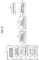
- a first embodiment of a sound field control system of the invention will be described with reference to Fig. 10.
- a configuration of the embodiment comprises reverberation characteristic measuring means 31 including a speaker 2, a microphone 3, a test signal generator 4, an analyzer 7 and a recorder 8, reverberation difference detection means 32, addition information calculation means 33, and information addition means 34.
- the reverberation characteristic measuring means 31 is means for measuring reverberation characteristics of an original sound field and a reproduction sound field; and comprises a speaker 2, a test signal generator 4 for generating a signal for measurement inputted to the speaker 2, for example, an impulse signal, a microphone 3 for collecting a sound wave issued from the speaker 2, an analyzer 7 for obtaining the reverberation characteristics by analyzing an impulse response between the speaker 2 and the microphone 3 from the sound wave collected by the microphone 3, and a recorder 8 for recording data of the reverberation characteristics as described with reference to Fig. 1. It may further comprise an amplifier for adjusting a signal level inputted to the speaker 2 or a level of a signal collected by the microphone 3.
- the speaker 2 is driven by the impulse signal from the test signal generator 4 and an output is produced as a sound wave and its sound wave is collected by the microphone 3 placed in a predetermined position of the front of the speaker 2 and from the collected signal, the reverberation characteristics are obtained by the analyzer 7.
- the microphone 3 is set in a position corresponding to the head of the case that a listener listens.
- the reverberation difference detection means 32 is means for detecting a difference between the reverberation characteristics from the reverberation characteristics of the original sound field and the reproduction sound field measured by the reverberation characteristic measuring means 31.
- the addition information calculation means 33 is means for obtaining addition information capable of obtaining realism similar to that of the original sound field, that is, a reflected sound pattern added to a reproduction sound source 35 of the reproduction sound field based on the difference between the reverberation characteristics of the original sound field and the reproduction sound field obtained by the reverberation difference detection means 32.
- the information addition means 34 is means for adding the reflected sound pattern obtained by the addition information calculation means 33 to the sound source 35 and producing an output.
- An output signal is inputted to the speaker through an amplifier and is issued as a sound signal or is recorded on a record medium such as a disk.
- sound reproduction in the reproduction sound field can be performed in a state close to environment in the original sound field.
- M-sequence noise or a time stretched pulse can also be used instead of the impulse signal is similar to the above fact.
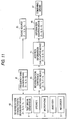
- a second embodiment of a sound field control system of the invention will be described with reference to Fig. 11.
- a configuration of the embodiment comprises frequency band division means 41 , reverberation characteristic measuring means 42, reverberation difference detection means 43, addition information calculation means 44, information addition means 46, and combining means 47.
- the frequency band division means 41 is means for dividing sound into predetermined frequency bands (f1 to f2, f2 to f3, ... ). Reverberation characteristics vary depending on frequency bands, and the reverberation characteristics of a high frequency attenuate rapidly as compared with those of a low frequency. Therefore, the division into the predetermined frequency bands is made in order to generate a reflected sound pattern every the frequency band and add it to a sound source 45. In amanner similar to the above in the division, for example, it is considered that a center frequency is divided into nine bands of 63, 125, 250, 500, 1 k, 2 k, 4 k, 8 k, 16 kHz .
- the reverberation characteristic measuring means 42, the reverberation difference detection means 43, the addition information calculation means 44 and the information addition means 46 differ from those of the first embodiment only in acting every the divided frequency band, and the other functions and action are equal to those of the first embodiment.
- the combiningmeans 47 is a step of combining and outputting a signal in which the reflected sound pattern is added to the sound source 45 every the frequency band, and is means for reconstructing reproduction sound to which the reflected sound pattern is added.
- the fact that an output signal is inputted to a speaker through an amplifier and is issued as a sound signal or is recorded on a record medium such as a disk is also similar to that of the first embodiment.
- the modified example has a system configuration in which a signal from a sound source 35 is inputted to frequency band division means 51 corresponding to divided frequency bands, that is, band-pass filters and addition information, that is, a reflected sound pattern is added to a signal of a passing frequency by information addition means 52 and thereafter a corrected sound signal of each the frequency band is combined by combining means 53 to produce an output.
- the reflected sound pattern added by the information addition means 52 needs to be obtained previously with respect to the respective frequency bands by the procedure described with reference to Figs. 4 to 7. In the case that an original sound field and a reproduction sound field are fixed always, the reflected sound pattern may be obtained once and a system configuration is also simple.
- the frequency band division means 51 and the information addition means 52 can be replaced backward and forward with respect to an input signal.
- gain adjusting means 54 are respectively provided in the back stage of the information addition means 52 shown in the first modified example. After adding reflected sound patterns to respective sound signals of frequency bands, a level of the signal can be adjusted every frequencyband and it is easy to adjust frequency characteristics over all the frequency bands. Also, in a manner similar to the first modified example, the frequency band division means 51 and the information addition means 52 can be replaced backward and forward with respect to an input signal.
- a third modified example of a sound field control system of the invention will be described with reference to Fig. 14.
- the frequency band division means 51, the information addition means 52 and the gain adjusting means 54 are replaced with filters 55.
- the filters 55 are filters substantially matched with transfer functions from the frequency band division means 51 to the gain adjusting means 54 to be formed.
- a system configuration becomes very simple.
- system can also be configured by one filter 56 substantially matched with a transfer function between input and output of a signal.
- the invention is not limited to the embodiments described above, and can be changed properly without departing from the claims and the subj ect matter or the idea of the invention capable of being read from the whole specification, and a sound field control method and a sound field control system with such a change are also included in the technical idea of the invention.
- control is targeted for environment reproducing sound, namely reverberation characteristics specific to a reproduction sound field, so that unlike pinpoint control in a listening position of a trans-aural system, reproduction sound with realism equal to that of a wide room can be obtained even when a listening position deviates. Therefore, also in the case of a narrow room interior like a car, it can listen with realism similar to that of the case of listening in a wide room and it is an extremely effective system.
- a stable approximate filter can be used and it can be configured by a relatively small system.
Landscapes
- Engineering & Computer Science (AREA)
- Signal Processing (AREA)
- Multimedia (AREA)
- Physics & Mathematics (AREA)
- Acoustics & Sound (AREA)
- Stereophonic System (AREA)
- Reverberation, Karaoke And Other Acoustics (AREA)
Applications Claiming Priority (2)
| Application Number | Priority Date | Filing Date | Title |
|---|---|---|---|
| JP2002053483A JP4059478B2 (ja) | 2002-02-28 | 2002-02-28 | 音場制御方法及び音場制御システム |
| JP2002053483 | 2002-02-28 |
Publications (3)
| Publication Number | Publication Date |
|---|---|
| EP1341399A2 true EP1341399A2 (de) | 2003-09-03 |
| EP1341399A3 EP1341399A3 (de) | 2004-09-29 |
| EP1341399B1 EP1341399B1 (de) | 2014-06-18 |
Family
ID=27678554
Family Applications (1)
| Application Number | Title | Priority Date | Filing Date |
|---|---|---|---|
| EP02258805.7A Expired - Lifetime EP1341399B1 (de) | 2002-02-28 | 2002-12-19 | Verfahren und System zur Schallfeldsteuerung |
Country Status (3)
| Country | Link |
|---|---|
| US (1) | US6909041B2 (de) |
| EP (1) | EP1341399B1 (de) |
| JP (1) | JP4059478B2 (de) |
Cited By (4)
| Publication number | Priority date | Publication date | Assignee | Title |
|---|---|---|---|---|
| WO2006116883A1 (de) * | 2005-05-01 | 2006-11-09 | Anocsys Ag | Verfahren zur kompensation von änderungen reproduzierter audiosignale und eine vorrichtung |
| EP1571884A3 (de) * | 2004-03-02 | 2008-08-20 | Sony Corporation | Verfahren und Vorrichtung zur Tonwiedergabe |
| EP1635612A3 (de) * | 2004-08-27 | 2008-10-08 | Sony Corporation | Vorrichtung und System zur Audiowiedergabe |
| EP2254355A3 (de) * | 2009-05-19 | 2013-06-26 | Yamaha Corporation | Schallfeldsteuerungsvorrichtung |
Families Citing this family (43)
| Publication number | Priority date | Publication date | Assignee | Title |
|---|---|---|---|---|
| GB0301093D0 (en) * | 2003-01-17 | 2003-02-19 | 1 Ltd | Set-up method for array-type sound systems |
| JP4234174B2 (ja) | 2004-06-30 | 2009-03-04 | パイオニア株式会社 | 残響調整装置、残響調整方法、残響調整プログラムおよびそれを記録した記録媒体、並びに、音場補正システム |
| WO2006004099A1 (ja) | 2004-07-05 | 2006-01-12 | Pioneer Corporation | 残響調整装置、残響補正方法、および、音響再生システム |
| JP2006030443A (ja) * | 2004-07-14 | 2006-02-02 | Sony Corp | 記録媒体、記録装置及び方法、データ処理装置及び方法、データ出力装置及び方法 |
| US8284947B2 (en) | 2004-12-01 | 2012-10-09 | Qnx Software Systems Limited | Reverberation estimation and suppression system |
| ATE459216T1 (de) * | 2005-06-28 | 2010-03-15 | Akg Acoustics Gmbh | Verfahren zur simulierung eines raumeindrucks und/oder schalleindrucks |
| JP2007280485A (ja) | 2006-04-05 | 2007-10-25 | Sony Corp | 記録装置、再生装置、記録再生装置、記録方法、再生方法および記録再生方法並びに記録媒体 |
| WO2008111143A1 (ja) * | 2007-03-09 | 2008-09-18 | Pioneer Corporation | 音場再生装置及び音場再生方法 |
| JP2009128559A (ja) * | 2007-11-22 | 2009-06-11 | Casio Comput Co Ltd | 残響効果付加装置 |
| JP5151483B2 (ja) * | 2008-01-07 | 2013-02-27 | ヤマハ株式会社 | 係数測定装置、効果付与装置、および楽音発生装置 |
| WO2010114409A1 (ru) * | 2009-04-01 | 2010-10-07 | Zakirov Azat Fuatovich | Способ воспроизведения аудиозаписи с моделированием акустических характеристик условий проведения записи |
| GB2471089A (en) * | 2009-06-16 | 2010-12-22 | Focusrite Audio Engineering Ltd | Audio processing device using a library of virtual environment effects |
| JP5672748B2 (ja) | 2010-03-31 | 2015-02-18 | ヤマハ株式会社 | 音場制御装置 |
| JP5699844B2 (ja) * | 2011-07-28 | 2015-04-15 | 富士通株式会社 | 残響抑制装置および残響抑制方法並びに残響抑制プログラム |
| US9084058B2 (en) | 2011-12-29 | 2015-07-14 | Sonos, Inc. | Sound field calibration using listener localization |
| JP2013143744A (ja) * | 2012-01-12 | 2013-07-22 | Denso Corp | 音像提示装置 |
| US9219460B2 (en) | 2014-03-17 | 2015-12-22 | Sonos, Inc. | Audio settings based on environment |
| US9106192B2 (en) | 2012-06-28 | 2015-08-11 | Sonos, Inc. | System and method for device playback calibration |
| US8822804B1 (en) * | 2013-02-09 | 2014-09-02 | Vladimir Vassilev | Digital aerophones and dynamic impulse response systems |
| US9264839B2 (en) | 2014-03-17 | 2016-02-16 | Sonos, Inc. | Playback device configuration based on proximity detection |
| US9952825B2 (en) | 2014-09-09 | 2018-04-24 | Sonos, Inc. | Audio processing algorithms |
| JP6056842B2 (ja) * | 2014-12-26 | 2017-01-11 | ヤマハ株式会社 | 音場制御装置 |
| WO2017007848A1 (en) | 2015-07-06 | 2017-01-12 | Dolby Laboratories Licensing Corporation | Estimation of reverberant energy component from active audio source |
| US9693165B2 (en) | 2015-09-17 | 2017-06-27 | Sonos, Inc. | Validation of audio calibration using multi-dimensional motion check |
| CN111314826B (zh) | 2015-09-17 | 2021-05-14 | 搜诺思公司 | 由计算设备执行的方法及相应计算机可读介质和计算设备 |
| US9743207B1 (en) | 2016-01-18 | 2017-08-22 | Sonos, Inc. | Calibration using multiple recording devices |
| US11106423B2 (en) * | 2016-01-25 | 2021-08-31 | Sonos, Inc. | Evaluating calibration of a playback device |
| US10003899B2 (en) | 2016-01-25 | 2018-06-19 | Sonos, Inc. | Calibration with particular locations |
| US9864574B2 (en) | 2016-04-01 | 2018-01-09 | Sonos, Inc. | Playback device calibration based on representation spectral characteristics |
| US9860662B2 (en) | 2016-04-01 | 2018-01-02 | Sonos, Inc. | Updating playback device configuration information based on calibration data |
| US9763018B1 (en) | 2016-04-12 | 2017-09-12 | Sonos, Inc. | Calibration of audio playback devices |
| US9794710B1 (en) | 2016-07-15 | 2017-10-17 | Sonos, Inc. | Spatial audio correction |
| US10372406B2 (en) | 2016-07-22 | 2019-08-06 | Sonos, Inc. | Calibration interface |
| US10459684B2 (en) | 2016-08-05 | 2019-10-29 | Sonos, Inc. | Calibration of a playback device based on an estimated frequency response |
| AU2018353008B2 (en) | 2017-10-17 | 2023-04-20 | Magic Leap, Inc. | Mixed reality spatial audio |
| IL305799B1 (en) | 2018-02-15 | 2024-06-01 | Magic Leap Inc | Virtual reverberation in mixed reality |
| US10299061B1 (en) | 2018-08-28 | 2019-05-21 | Sonos, Inc. | Playback device calibration |
| US11206484B2 (en) | 2018-08-28 | 2021-12-21 | Sonos, Inc. | Passive speaker authentication |
| US10734965B1 (en) | 2019-08-12 | 2020-08-04 | Sonos, Inc. | Audio calibration of a portable playback device |
| US11304017B2 (en) * | 2019-10-25 | 2022-04-12 | Magic Leap, Inc. | Reverberation fingerprint estimation |
| JP7496972B2 (ja) | 2021-01-22 | 2024-06-10 | 株式会社安藤・間 | 音場解析装置、音場解析方法及びプログラム |
| WO2024029634A1 (ja) * | 2022-08-03 | 2024-02-08 | マクセル株式会社 | 放送受信装置、コンテンツ保護方法、残響音付加処理方法および放送受信装置の制御方法 |
| WO2024035873A1 (en) * | 2022-08-12 | 2024-02-15 | Ibiquity Digital Corporation | Ambiance expansion system for a vehicle |
Family Cites Families (11)
| Publication number | Priority date | Publication date | Assignee | Title |
|---|---|---|---|---|
| JPS5666919A (en) * | 1979-11-05 | 1981-06-05 | Nippon Columbia Co Ltd | Automatic corrector for sound field |
| JPS57188119A (en) * | 1981-11-07 | 1982-11-19 | Sony Corp | Acoustic character correcting device |
| JP2646210B2 (ja) * | 1987-05-27 | 1997-08-27 | ヤマハ株式会社 | 電気音響的残響支援装置 |
| JP2892205B2 (ja) * | 1991-11-28 | 1999-05-17 | 株式会社ケンウッド | 伝送周波数特性補正装置 |
| JP2737595B2 (ja) * | 1993-03-26 | 1998-04-08 | ヤマハ株式会社 | 音場制御装置 |
| US5572443A (en) * | 1993-05-11 | 1996-11-05 | Yamaha Corporation | Acoustic characteristic correction device |
| JPH07334181A (ja) * | 1994-06-08 | 1995-12-22 | Matsushita Electric Ind Co Ltd | 残響音生成装置 |
| US6399868B1 (en) * | 2000-09-28 | 2002-06-04 | Roland Corporation | Sound effect generator and audio system |
| JP3823824B2 (ja) * | 2001-12-27 | 2006-09-20 | ヤマハ株式会社 | 電子楽音発生装置および信号処理特性調整方法 |
| JP3843841B2 (ja) * | 2002-01-10 | 2006-11-08 | ヤマハ株式会社 | 電子楽器 |
| JP3767493B2 (ja) * | 2002-02-19 | 2006-04-19 | ヤマハ株式会社 | 音響補正フィルタの設計方法、音響補正フィルタの作成方法、音響補正フィルタのフィルタ特性決定装置および音響信号出力装置 |
-
2002
- 2002-02-28 JP JP2002053483A patent/JP4059478B2/ja not_active Expired - Fee Related
- 2002-12-19 EP EP02258805.7A patent/EP1341399B1/de not_active Expired - Lifetime
- 2002-12-19 US US10/322,662 patent/US6909041B2/en not_active Expired - Fee Related
Non-Patent Citations (1)
| Title |
|---|
| None |
Cited By (6)
| Publication number | Priority date | Publication date | Assignee | Title |
|---|---|---|---|---|
| EP1571884A3 (de) * | 2004-03-02 | 2008-08-20 | Sony Corporation | Verfahren und Vorrichtung zur Tonwiedergabe |
| EP1635612A3 (de) * | 2004-08-27 | 2008-10-08 | Sony Corporation | Vorrichtung und System zur Audiowiedergabe |
| US7773755B2 (en) | 2004-08-27 | 2010-08-10 | Sony Corporation | Reproduction apparatus and reproduction system |
| WO2006116883A1 (de) * | 2005-05-01 | 2006-11-09 | Anocsys Ag | Verfahren zur kompensation von änderungen reproduzierter audiosignale und eine vorrichtung |
| EP2254355A3 (de) * | 2009-05-19 | 2013-06-26 | Yamaha Corporation | Schallfeldsteuerungsvorrichtung |
| US8488802B2 (en) | 2009-05-19 | 2013-07-16 | Yamaha Corporation | Sound field control device |
Also Published As
| Publication number | Publication date |
|---|---|
| US20030159569A1 (en) | 2003-08-28 |
| EP1341399B1 (de) | 2014-06-18 |
| EP1341399A3 (de) | 2004-09-29 |
| US6909041B2 (en) | 2005-06-21 |
| JP4059478B2 (ja) | 2008-03-12 |
| JP2003255955A (ja) | 2003-09-10 |
Similar Documents
| Publication | Publication Date | Title |
|---|---|---|
| EP1341399B1 (de) | Verfahren und System zur Schallfeldsteuerung | |
| US4823391A (en) | Sound reproduction system | |
| KR101234973B1 (ko) | 필터 특징을 발생시키는 장치 및 방법 | |
| JP5637661B2 (ja) | 時変性の指向特性を有する音源を録音および再生する方法 | |
| US6363155B1 (en) | Process and device for mixing sound signals | |
| KR100608025B1 (ko) | 2채널 헤드폰용 입체 음향 생성 방법 및 장치 | |
| JP3584800B2 (ja) | 音場再現方法およびその装置 | |
| EP1571884A2 (de) | Verfahren und Vorrichtung zur Tonwiedergabe | |
| JP5611970B2 (ja) | オーディオ信号を変換するためのコンバータ及び方法 | |
| JPH02503721A (ja) | 電気音響システム | |
| KR20050060789A (ko) | 가상 음향 재생 방법 및 그 장치 | |
| JPH0787589A (ja) | 立体感及び/又は音響特性感のシミュレーション方法及び装置 | |
| JP5986426B2 (ja) | 音響処理装置、音響処理方法 | |
| JP4786701B2 (ja) | 音響補正装置、音響測定装置、音響再生装置、音響補正方法及び音響測定方法 | |
| JP4904461B2 (ja) | 音声周波数応答処理システム | |
| JP4222276B2 (ja) | 再生システム | |
| JP2006517072A (ja) | マルチチャネル信号を用いて再生部を制御する方法および装置 | |
| JP2006279863A (ja) | 頭部伝達関数の補正方法 | |
| JP2006262015A (ja) | 音場特性測定方法、音場特性測定システム、増幅装置、及び音場特性測定装置 | |
| US20050013442A1 (en) | Sound field control system and sound field control method | |
| US20050053246A1 (en) | Automatic sound field correction apparatus and computer program therefor | |
| WO2018185733A1 (en) | Sound spatialization method | |
| JP4845407B2 (ja) | リファレンスフィルタの生成方法 | |
| JP4691662B2 (ja) | 頭外音像定位装置 | |
| JP2997665B2 (ja) | 音場再生装置 |
Legal Events
| Date | Code | Title | Description |
|---|---|---|---|
| PUAI | Public reference made under article 153(3) epc to a published international application that has entered the european phase |
Free format text: ORIGINAL CODE: 0009012 |
|
| AK | Designated contracting states |
Kind code of ref document: A2 Designated state(s): AT BE BG CH CY CZ DE DK EE ES FI FR GB GR IE IT LI LU MC NL PT SE SI SK TR |
|
| AX | Request for extension of the european patent |
Extension state: AL LT LV MK RO |
|
| PUAL | Search report despatched |
Free format text: ORIGINAL CODE: 0009013 |
|
| AK | Designated contracting states |
Kind code of ref document: A3 Designated state(s): AT BE BG CH CY CZ DE DK EE ES FI FR GB GR IE IT LI LU MC NL PT SE SI SK TR |
|
| AX | Request for extension of the european patent |
Extension state: AL LT LV MK RO |
|
| RIC1 | Information provided on ipc code assigned before grant |
Ipc: 7G 10K 15/08 B Ipc: 7H 04S 7/00 A |
|
| 17P | Request for examination filed |
Effective date: 20050316 |
|
| AKX | Designation fees paid |
Designated state(s): DE FR GB |
|
| RAP1 | Party data changed (applicant data changed or rights of an application transferred) |
Owner name: PIONEER CORPORATION |
|
| REG | Reference to a national code |
Ref country code: DE Ref legal event code: R079 Ref document number: 60246350 Country of ref document: DE Free format text: PREVIOUS MAIN CLASS: H04S0007000000 Ipc: H04M0009080000 |
|
| GRAP | Despatch of communication of intention to grant a patent |
Free format text: ORIGINAL CODE: EPIDOSNIGR1 |
|
| RIC1 | Information provided on ipc code assigned before grant |
Ipc: H04S 7/00 20060101ALI20131205BHEP Ipc: H04M 9/08 20060101AFI20131205BHEP |
|
| INTG | Intention to grant announced |
Effective date: 20140103 |
|
| GRAS | Grant fee paid |
Free format text: ORIGINAL CODE: EPIDOSNIGR3 |
|
| GRAA | (expected) grant |
Free format text: ORIGINAL CODE: 0009210 |
|
| AK | Designated contracting states |
Kind code of ref document: B1 Designated state(s): DE FR GB |
|
| REG | Reference to a national code |
Ref country code: GB Ref legal event code: FG4D Ref country code: GB Ref legal event code: 746 Effective date: 20140528 |
|
| REG | Reference to a national code |
Ref country code: DE Ref legal event code: R096 Ref document number: 60246350 Country of ref document: DE Effective date: 20140731 Ref country code: DE Ref legal event code: R084 Ref document number: 60246350 Country of ref document: DE Effective date: 20140508 |
|
| PGFP | Annual fee paid to national office [announced via postgrant information from national office to epo] |
Ref country code: GB Payment date: 20141217 Year of fee payment: 13 |
|
| REG | Reference to a national code |
Ref country code: DE Ref legal event code: R081 Ref document number: 60246350 Country of ref document: DE Owner name: ONKYO KABUSHIKI KAISHA D/B/A ONKYO CORP., NEYA, JP Free format text: FORMER OWNER: PIONEER CORP., TOKIO/TOKYO, JP Effective date: 20150113 Ref country code: DE Ref legal event code: R081 Ref document number: 60246350 Country of ref document: DE Owner name: ONKYO KABUSHIKI KAISHA D/B/A ONKYO CORP., NEYA, JP Free format text: FORMER OWNER: PIONEER CORP., TOKIO/TOKYO, JP Effective date: 20140618 Ref country code: DE Ref legal event code: R081 Ref document number: 60246350 Country of ref document: DE Owner name: PIONEER CORPORATION, JP Free format text: FORMER OWNER: PIONEER CORP., TOKIO/TOKYO, JP Effective date: 20140618 Ref country code: DE Ref legal event code: R081 Ref document number: 60246350 Country of ref document: DE Owner name: PIONEER CORPORATION, JP Free format text: FORMER OWNER: PIONEER CORP., TOKIO/TOKYO, JP Effective date: 20150113 |
|
| PGFP | Annual fee paid to national office [announced via postgrant information from national office to epo] |
Ref country code: FR Payment date: 20141208 Year of fee payment: 13 |
|
| REG | Reference to a national code |
Ref country code: DE Ref legal event code: R097 Ref document number: 60246350 Country of ref document: DE |
|
| PLBE | No opposition filed within time limit |
Free format text: ORIGINAL CODE: 0009261 |
|
| STAA | Information on the status of an ep patent application or granted ep patent |
Free format text: STATUS: NO OPPOSITION FILED WITHIN TIME LIMIT |
|
| PGFP | Annual fee paid to national office [announced via postgrant information from national office to epo] |
Ref country code: DE Payment date: 20141216 Year of fee payment: 13 |
|
| 26N | No opposition filed |
Effective date: 20150319 |
|
| REG | Reference to a national code |
Ref country code: DE Ref legal event code: R081 Ref document number: 60246350 Country of ref document: DE Owner name: ONKYO KABUSHIKI KAISHA D/B/A ONKYO CORP., NEYA, JP Free format text: FORMER OWNER: PIONEER CORPORATION, KANAGAWA, JP |
|
| REG | Reference to a national code |
Ref country code: GB Ref legal event code: 732E Free format text: REGISTERED BETWEEN 20150618 AND 20150624 |
|
| REG | Reference to a national code |
Ref country code: FR Ref legal event code: TP Owner name: ONKYO KABUSHIKI KAISHA D/B/A ONKYO CORPORATION, JP Effective date: 20150918 |
|
| REG | Reference to a national code |
Ref country code: DE Ref legal event code: R119 Ref document number: 60246350 Country of ref document: DE |
|
| GBPC | Gb: european patent ceased through non-payment of renewal fee |
Effective date: 20151219 |
|
| REG | Reference to a national code |
Ref country code: FR Ref legal event code: ST Effective date: 20160831 |
|
| PG25 | Lapsed in a contracting state [announced via postgrant information from national office to epo] |
Ref country code: DE Free format text: LAPSE BECAUSE OF NON-PAYMENT OF DUE FEES Effective date: 20160701 Ref country code: GB Free format text: LAPSE BECAUSE OF NON-PAYMENT OF DUE FEES Effective date: 20151219 |
|
| PG25 | Lapsed in a contracting state [announced via postgrant information from national office to epo] |
Ref country code: FR Free format text: LAPSE BECAUSE OF NON-PAYMENT OF DUE FEES Effective date: 20151231 |