EP1339596B1 - Elektrische lenkvorrichtung für kraftfahrzeuge - Google Patents
Elektrische lenkvorrichtung für kraftfahrzeuge Download PDFInfo
- Publication number
- EP1339596B1 EP1339596B1 EP01993378A EP01993378A EP1339596B1 EP 1339596 B1 EP1339596 B1 EP 1339596B1 EP 01993378 A EP01993378 A EP 01993378A EP 01993378 A EP01993378 A EP 01993378A EP 1339596 B1 EP1339596 B1 EP 1339596B1
- Authority
- EP
- European Patent Office
- Prior art keywords
- clutch
- worm gear
- elastic
- flange
- input shaft
- Prior art date
- Legal status (The legal status is an assumption and is not a legal conclusion. Google has not performed a legal analysis and makes no representation as to the accuracy of the status listed.)
- Expired - Lifetime
Links
- 125000006850 spacer group Chemical group 0.000 claims description 22
- 230000000295 complement effect Effects 0.000 claims 1
- 230000005489 elastic deformation Effects 0.000 claims 1
- 230000008878 coupling Effects 0.000 description 9
- 238000010168 coupling process Methods 0.000 description 9
- 238000005859 coupling reaction Methods 0.000 description 9
- 210000001331 nose Anatomy 0.000 description 4
- 238000004804 winding Methods 0.000 description 3
- 230000005540 biological transmission Effects 0.000 description 2
- 238000013016 damping Methods 0.000 description 2
- 230000000694 effects Effects 0.000 description 2
- 230000003139 buffering effect Effects 0.000 description 1
- 238000012885 constant function Methods 0.000 description 1
- 238000005516 engineering process Methods 0.000 description 1
- 230000001629 suppression Effects 0.000 description 1
Images

Classifications
-
- F—MECHANICAL ENGINEERING; LIGHTING; HEATING; WEAPONS; BLASTING
- F16—ENGINEERING ELEMENTS AND UNITS; GENERAL MEASURES FOR PRODUCING AND MAINTAINING EFFECTIVE FUNCTIONING OF MACHINES OR INSTALLATIONS; THERMAL INSULATION IN GENERAL
- F16H—GEARING
- F16H55/00—Elements with teeth or friction surfaces for conveying motion; Worms, pulleys or sheaves for gearing mechanisms
- F16H55/02—Toothed members; Worms
- F16H55/14—Construction providing resilience or vibration-damping
-
- B—PERFORMING OPERATIONS; TRANSPORTING
- B62—LAND VEHICLES FOR TRAVELLING OTHERWISE THAN ON RAILS
- B62D—MOTOR VEHICLES; TRAILERS
- B62D5/00—Power-assisted or power-driven steering
- B62D5/04—Power-assisted or power-driven steering electrical, e.g. using an electric servo-motor connected to, or forming part of, the steering gear
- B62D5/0409—Electric motor acting on the steering column
-
- Y—GENERAL TAGGING OF NEW TECHNOLOGICAL DEVELOPMENTS; GENERAL TAGGING OF CROSS-SECTIONAL TECHNOLOGIES SPANNING OVER SEVERAL SECTIONS OF THE IPC; TECHNICAL SUBJECTS COVERED BY FORMER USPC CROSS-REFERENCE ART COLLECTIONS [XRACs] AND DIGESTS
- Y10—TECHNICAL SUBJECTS COVERED BY FORMER USPC
- Y10T—TECHNICAL SUBJECTS COVERED BY FORMER US CLASSIFICATION
- Y10T74/00—Machine element or mechanism
- Y10T74/19—Gearing
- Y10T74/19633—Yieldability in gear trains
-
- Y—GENERAL TAGGING OF NEW TECHNOLOGICAL DEVELOPMENTS; GENERAL TAGGING OF CROSS-SECTIONAL TECHNOLOGIES SPANNING OVER SEVERAL SECTIONS OF THE IPC; TECHNICAL SUBJECTS COVERED BY FORMER USPC CROSS-REFERENCE ART COLLECTIONS [XRACs] AND DIGESTS
- Y10—TECHNICAL SUBJECTS COVERED BY FORMER USPC
- Y10T—TECHNICAL SUBJECTS COVERED BY FORMER US CLASSIFICATION
- Y10T74/00—Machine element or mechanism
- Y10T74/19—Gearing
- Y10T74/19642—Directly cooperating gears
- Y10T74/19698—Spiral
- Y10T74/19828—Worm
-
- Y—GENERAL TAGGING OF NEW TECHNOLOGICAL DEVELOPMENTS; GENERAL TAGGING OF CROSS-SECTIONAL TECHNOLOGIES SPANNING OVER SEVERAL SECTIONS OF THE IPC; TECHNICAL SUBJECTS COVERED BY FORMER USPC CROSS-REFERENCE ART COLLECTIONS [XRACs] AND DIGESTS
- Y10—TECHNICAL SUBJECTS COVERED BY FORMER USPC
- Y10T—TECHNICAL SUBJECTS COVERED BY FORMER US CLASSIFICATION
- Y10T74/00—Machine element or mechanism
- Y10T74/19—Gearing
- Y10T74/1987—Rotary bodies
- Y10T74/19893—Sectional
- Y10T74/19907—Sound deadening
Definitions
- the invention relates to an electric steering device according to the one defined in the preamble of claim 1 Art.
- a steering device is, for example, from known from WO 0023313A.
- Electric steering devices such as those from the prior art Technology are known to have an input shaft that is in operative connection with a steering handwheel and is used for Transmission of one for steering wheels to be steered required torque is used.
- An output link stands in active connection with the wheels to be steered.
- An electric motor, through the directly or indirectly an assistant the output link can be exercised is on the power steering arranged.
- the input shaft and the output link are connected to each other via a torsionally flexible link connected that between the input shaft and the Output member a limited twisting movement is possible.
- the output link is designed as a drive pinion and protrudes a rack with steerable wheels of a motor vehicle in operative connection.
- the rack is above a, preferably Reduction gear designed as a worm gear with a servomotor designed as an electric motor in.Wirkharm.
- the output link is via the worm gear connected to an electric motor.
- the main components of the electric motor are a rotor and a stator.
- the stator is fixed to the housing, the rotor is via a drive shaft with a worm shaft of the worm gear connected.
- Such an electric steering device is for example known from DE 197 52 075 A1.
- This electric steering device consists of an electric motor Worm gear, in which the shaft of the worm is held elastically in the transmission housing. Between the Worm gear and the worm of the worm gear is provided a game. The screw is in the axial direction slidably supported and supported by elastic elements on the gearbox. This allows the negative Influences on by the electromotive actuator the steering are transferred to be reduced.
- the electric steering device described in DE 197 52 075 A1 has the disadvantage that only a noise reduction, but no noise suppression can be achieved can. Furthermore, noises can be heard when driving against the End stop occur, not be eliminated. About the entire lifespan cannot have a constant function can be guaranteed because the elastic elements by external influences such as temperature and Dirt, will change in their characteristics.
- the present invention is based on the object Electric steering device to represent a constant Functionality with regard to the entire service life structure-borne noise decoupling and end stop damping guaranteed.
- the object on which the invention is based is achieved by also having the characteristic features of the main claim, Generic electrical steering device solved.
- the task is solved by an axial and radial axis Decoupling and torsion damping, especially through a structure-borne noise decoupling of the worm gear from Steering spindle and drive pinion.
- the worm wheel as a coupling part of an elastic compensating coupling formed, the other coupling part shaped as a flange is connected to the input shaft in a rotationally fixed manner is.
- Both coupling parts are by an elastic spacer coupled with each other, with a defined End stop is provided at a particular Torque is reached.
- the stiffness from ring gear to input shaft can be by adjusting the contour and shape of the elastic spacer change.
- the electric steering device for motor vehicles contains 1 a steering gear a rack and pinion steering 1.
- a rack and pinion steering 1 is generally known and is therefore not described in more detail here explained.
- a rack, not shown, of the rack and pinion steering 1 forms an output link together with two steering push rods 5 and 6, that with wheels, not shown, to be steered is in operative connection.
- the rack also forms the drive part of the steering.
- a supporting torque can be exerted on the input shaft 2 by an electric motor 7.
- the electric motor 7 is arranged such that its axis is perpendicular to the axis of the input shaft 2 and thus the drive pinion. However, its axis can also be at a different angle to the axis of the input shaft 2.
- the electric motor 7 can be arranged such that its axis is arranged parallel to the axis of the input shaft 2 and thus also of the drive pinion or another part of the steering column 3. In the two types of arrangement of the electric motor 7 described so far, it acts on the input shaft 2 with the drive pinion of the rack and pinion steering 1.
- the electric motor 7 can be arranged so that its axis is parallel or coaxial to the longitudinal direction of the rack of the rack and pinion steering 1.
- the electric motor 7 is advantageously an asynchronous motor educated.
- the asynchronous motor essentially exists of a rotatable rotor 8 and a fixed winding 9.
- the torque is generated from the outside Rotary field specified via control and switching elements.
- the Rotor 8 is expediently as a squirrel-cage rotor or as Short-circuit rotor executed. Because such an electric motor no permanent magnets are required in the event of a fault in the electrical or electronic part of the steering device generates no magnetic field when rotating the rotor 8, which would influence or inhibit the rotary movement of the rotor 8. This ensures that the power flow from the steering wheel 4 to the steered wheels in the event of an accident is affected.
- Fig. 2 In the embodiment shown in Fig. 2 is the Winding 9 of the electric motor 7 space-saving.directly in one Housing 10 integrated and by a stop 11 and one axially biased cover 12 against axial and radial movement secured.
- the torque generated by the electric motor 7 is about a worm gear consisting of worm 13 and Worm gear 14, transmitted to the input shaft 2.
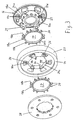
- FIG 3 is an exploded view of the elastic Compensating clutch shown, of which the worm wheel 14 in Figure 2 is a part.
- This has a ring gear 23, the teeth not are shown, in which the screw 13 (Fig. 2) engages.
- the other coupling part of the elastic compensating coupling, namely the flange 16 is rotatably with of the input shafts 2 (not shown in FIG. 3) (see 1 and 2) connected, namely via a nozzle, the End face with 16a and its outer surface with 24d is designated.
- the two parts 14 and 16 of the compensating coupling are supplemented through an annular, elastic spacer 17 with extensions 20.
- the worm wheel 14 is designed with mirror symmetry the same appearance on the invisible back like on the front. After assembling it is Worm gear 14 mounted on the spacer 17, the is in turn mounted on the neck of the flange 16. The Inner surface 24c of the worm wheel 14 is therefore on the Ring outer surface 24a of the spacer 17.
- For the Extensions 20 of the spacer 17 are bulges 26 of recesses 22 provided in the worm wheel 14. In The extensions 20 have space for these bulges 26.
- the front of the worm wheel 14 is still by a second spacer 27 and a second Flange 28 added to a further compensating coupling.
- the flanges 16 and 28 are through Noses 21 connected to each other.
- An internal toothing also engages of the second flange 28 in a toothing of Socket on the flange 16.
- the second elastic spacer 27 also sits on the when assembled Neck of the flange 16.
- the second flange 28 has its back the same pin 25 as the flange 16.
- the front surface 18a at the rear of the second flange 28 lies on the contact surface 18e of a bulge 26 in Worm gear 14 on.
- Lateral contact surfaces 19a, 19b of the Spacers 17 and 27 are located on lateral contact surfaces 19c, 19d of the pin 25 or on lateral contact surfaces 19e, 19f from bulges 26 in the worm wheel 14.
- the extensions 20 thus prevent the pin 25 from Side surfaces of the bulges 26 in the transfer of a Torque in one direction or the other immediately can touch.
- the spacers 17, 27 are also designed so broad that it is an immediate touch prevent parts 14 and 16 or 14 and 28 in the axial direction. And since the ring-shaped parts of the spacers 17, 27 between the outer surface 24d of the flange 16 and the inner surface 24c of the worm wheel 14 is also in the radial direction ensured that an immediate Contact between the neck of the flange 16 and the Worm gear 14 is avoided.
- the spacers 17, 27 thus form both in the axial and in the radial and finally a buffer between in the tangential direction the flange 16 (and thus the input shaft 2) and the worm wheel 14.
- the elastic buffering is in the tangential direction not unlimited, because the recesses 22 in the worm gear 14, through which the lugs 21 of the flange 16 engage, are only slightly larger (measured in the tangential direction) than the noses 21. This means that the noses 21 and the recesses 22 form mutual stops which come into effect if excessive in the transfer large torque the extensions 20 of the spacers 17, 27 are squeezed together by a certain amount.
Landscapes
- Engineering & Computer Science (AREA)
- Mechanical Engineering (AREA)
- General Engineering & Computer Science (AREA)
- Chemical & Material Sciences (AREA)
- Combustion & Propulsion (AREA)
- Transportation (AREA)
- Power Steering Mechanism (AREA)
- Connection Of Motors, Electrical Generators, Mechanical Devices, And The Like (AREA)
Description
- Fig. 1
- den Aufbau einer elektrischen Lenkvorrichtung für Kraftfahrzeuge in schematischer Darstellung,
- Fig. 2
- den Längsschnitt durch den Elektromotor aus Fig. 1 und
- Fig. 3
- eine Explosionsdarstellung des Schneckenrades aus Fig. 2.
Mit gleicher oder ähnlicher Wirkung kann der Elektromotor 7 derart angeordnet sein, daß seine Achse parallel zu der Achse der Eingangswelle 2 und damit auch des Antriebsritzels oder eines anderen Teils der Lenksäule 3 angeordnet ist.
In den beiden bisher beschriebenen Anordnungsarten des Elektromotors 7 wirkt dieser auf die Eingangswelle 2 mit dem Antriebsritzel der Zahnstangenlenkung 1. Ebenso kann der Elektromotor 7 so angeordnet werden, daß seine Achse parallel oder koaxial zur Längsrichtung der Zahnstange der Zahnstangenlenkung 1 liegt.
- 1
- Zahnstangenlenkung
- 2
- Eingangswelle
- 3
- Lenksäule
- 4
- Lenkhandrad
- 5
- Lenkschubstange
- 6
- Lenkschubstange
- 7
- Elektromotor
- 8
- Rotor
- 9
- Wicklung
- 10
- Gehäuse
- 11
- Anschlag
- 12
- Deckel
- 13
- Schnecke
- 14
- Schneckenrad
- 15 16
- Flansch
- 17
- Abstandshalter
- 18a, b, c, d
- Anlageflächen
- 19a, b, c, d
- Anlageflächen
- 20
- Fortsatz
- 21
- Nase
- 22
- Ausnehmung
- 23
- Zahnkranz
- 24a, b, c, d
- Anlageflächen
- 25
- Zapfen
- 26
- Ausbuchtung
- 27
- zweiter Abstandshalter
- 28
- zweiter Flansch
Claims (2)
- Elektrische Lenkvorrichtung für ein Kraftfahrzeug, mit einem Elektromotor (7) mit Schneckengetriebe, das aus einer Schnecke (13) und einem mit einer Eingangswelle (2) gekoppelten Schneckenrad (14) mit Zahnkranz (23) besteht, mit folgenden Merkmalengekennzeichnet durch Folgende Merkmale:das Schneckenrad (14) bildet eines der beiden miteinander zu kuppelnden Kupplungsteile (14, 16) einer elastischen Ausgleichskupplung, deren anderes Kupplungsteil (16) drehfest mit der Eingangswelle (2) verbunden ist,beide Kupplungsteile (14, 16) sind nur durch einen oder mehrere elastische Abstandshalter (17) miteinander gekoppeltder Eingangswelle (2) ist drehfest ein Flansch (16) zugeordnet,Flansch (16) und Schneckenrad (14) bilden die beiden miteinander zu kuppelnden-Kupplungsteile der elastischen Ausgleichskupplung zur Übertragung von Dehmomenten,beide Kupplungsteile (16, 14) sind durch den elastischen Abstandshalter (17) in axialer, radialer und tangentialer Richtung voneinander getrennt,der Abstandshalter (17) weist Anlageflächen (18a, 19a, 19b, 24a, 24b) auf, auf welche im Betrieb axiale, radiale und tangentiale Druckkräfte wirken, welche von korrespondierenden Anlageflächen (18c, 18d, 19c, 19d, 24b, 24d) eines der beiden Kupplungsteile (16, 14) ausgeübt werden,eines der beiden Kupplungsteile (16) weist wenigstens eine Nase (21) auf, die mit Spiel in eine größere Ausnehmung (22) des anderen Kupplungsteils (14) greift,ab einem bestimmten Drehmoment und entsprechender elastischer Verformung des Abstandshalters (17) ergänzen sich die Nase (21) und die Ausnehmung (22) nach Überwindung des Spiels zu gegenseitigen Anschlägen.
- Elektrische Lenkvorrichtung nach Anspruch 1 dadurch gekennzeichnet, daß das Schneckenrad (14) unter Zwischenschaltung des elastischen Abstandshalters (17) auf einem Stutzen (16a) gelagert ist, welcher Teil des anderen Kupplungsteils (16) ist.
Applications Claiming Priority (3)
| Application Number | Priority Date | Filing Date | Title |
|---|---|---|---|
| DE10056133 | 2000-11-13 | ||
| DE10056133A DE10056133A1 (de) | 2000-11-13 | 2000-11-13 | Elektrische Lenkvorrichtung für Kraftfahrzeuge |
| PCT/EP2001/012503 WO2002038432A1 (de) | 2000-11-13 | 2001-10-30 | Elektrische lenkvorrichtung für kraftfahrzeuge |
Publications (2)
| Publication Number | Publication Date |
|---|---|
| EP1339596A1 EP1339596A1 (de) | 2003-09-03 |
| EP1339596B1 true EP1339596B1 (de) | 2004-10-20 |
Family
ID=7663084
Family Applications (1)
| Application Number | Title | Priority Date | Filing Date |
|---|---|---|---|
| EP01993378A Expired - Lifetime EP1339596B1 (de) | 2000-11-13 | 2001-10-30 | Elektrische lenkvorrichtung für kraftfahrzeuge |
Country Status (5)
| Country | Link |
|---|---|
| US (1) | US7650809B2 (de) |
| EP (1) | EP1339596B1 (de) |
| JP (1) | JP3842215B2 (de) |
| DE (2) | DE10056133A1 (de) |
| WO (1) | WO2002038432A1 (de) |
Cited By (9)
| Publication number | Priority date | Publication date | Assignee | Title |
|---|---|---|---|---|
| WO2007098744A1 (de) * | 2006-03-02 | 2007-09-07 | Zf Friedrichshafen Ag | Schraubradgetriebe für zahnstangenlenkung |
| WO2007098745A1 (de) * | 2006-03-02 | 2007-09-07 | Zf Friedrichshafen Ag | Zahnradanordnung |
| DE102006030097B3 (de) * | 2006-06-28 | 2008-02-14 | Zf Friedrichshafen Ag | Schraubrad |
| DE102007000923A1 (de) | 2007-08-28 | 2009-03-05 | Zf Lenksysteme Gmbh | Getrieberad für eine elektrische Zahnstangenlenkung |
| WO2009094970A1 (de) | 2008-01-31 | 2009-08-06 | Zf Friedrichshafen Ag | Schraubrad mit dämpfung |
| DE102009027441A1 (de) | 2009-07-03 | 2011-01-05 | Zf Lenksysteme Gmbh | Schraubrad für ein Getriebe |
| DE102010049999A1 (de) * | 2010-10-29 | 2012-05-03 | Volkswagen Ag | Elektrische Lenkunterstützungsvorrichtung zur Anordnung an einer Lenksäule eines Kraftfahrzeugs |
| DE102012100503A1 (de) | 2012-01-23 | 2013-07-25 | Zf Lenksysteme Gmbh | Verfahren zum Herstellen eines Lagerrings für ein Kugellager für ein Servogetriebe |
| DE102012100492A1 (de) | 2012-01-23 | 2013-07-25 | Zf Lenksysteme Gmbh | Servogetriebe für eine hilfskraftlenkung |
Families Citing this family (32)
| Publication number | Priority date | Publication date | Assignee | Title |
|---|---|---|---|---|
| US6915716B2 (en) * | 2002-04-19 | 2005-07-12 | Illinois Tool Works Inc. | Roller/damper assembly |
| DE10326819A1 (de) * | 2003-06-13 | 2004-12-30 | Zf Lenksysteme Gmbh | Zahnrad für ein Lenksystem-Getriebe |
| US7159485B2 (en) * | 2003-08-07 | 2007-01-09 | Siemens Vdo Automotive Corporation | Cantilever dampened drive assembly for windowlift motors |
| DE10347780A1 (de) | 2003-10-15 | 2005-05-12 | Zf Lenksysteme Gmbh | Zahnrad für Schraubradgetriebe |
| US20080073816A1 (en) * | 2003-10-30 | 2008-03-27 | Stephan Oberle | Method for forming a gear |
| DE102004002847B4 (de) * | 2004-01-19 | 2013-01-10 | Ims Gear Gmbh | KFZ-Zahnradanordnung für ein KFZ-Hilfsgetriebe und Verfahren zum Herstellen einer solchen KFZ-Zahnradanordnung |
| DE102004064001B4 (de) * | 2004-01-19 | 2012-03-15 | Ims Gear Gmbh | KFZ-Zahnradanordnung für ein KFZ-Hilfsgetriebe sowie Flansch und Verfahren zum Herstellen einer solchen KFZ-Zahnradanordnung |
| DE102004064237B3 (de) * | 2004-01-19 | 2014-10-23 | Ims Gear Gmbh | KFZ-Zahnradanordnung für ein KFZ-Hilfsgetriebe sowie Flansch |
| US20060123942A1 (en) * | 2004-12-14 | 2006-06-15 | Facciolla Arthur O | Constructive arrangement in metallic gear |
| DE502006004548D1 (de) * | 2005-11-16 | 2009-09-24 | Ims Gear Gmbh | Kraftfahrzeug-zahnrad-anordnung für ein kraftfahrzebs-zahnradanordnung |
| JP5103856B2 (ja) * | 2006-10-05 | 2012-12-19 | 株式会社ジェイテクト | 電動パワーステアリング装置 |
| DE102007035970A1 (de) * | 2007-07-30 | 2009-02-12 | Ims Gear Gmbh | Elektrische Lenkvorrichtung für Kraftfahrzeuge |
| US8429995B2 (en) * | 2008-07-07 | 2013-04-30 | Asmo Co., Ltd. | Output power transmission device and motor with speed reducing mechanism |
| CN101649884B (zh) * | 2008-08-15 | 2013-11-13 | 德昌电机(深圳)有限公司 | 传动结构及具有所述传动结构的马达组件 |
| DE102010003354A1 (de) * | 2010-03-26 | 2011-09-29 | Brose Fahrzeugteile GmbH & Co. Kommanditgesellschaft, Würzburg | Einbau-Lenkungsmotoranordnung und Lenkungsvorrichtung |
| US8555836B2 (en) * | 2010-12-10 | 2013-10-15 | Delphi Technologies, Inc. | Electric drive camshaft phaser with torque rate limit at travel stops |
| DE102012102776A1 (de) | 2012-03-30 | 2013-10-02 | Zf Lenksysteme Gmbh | Schraubrad für eine elektromechanische lenkvorrichtung |
| DE102012102778A1 (de) | 2012-03-30 | 2013-10-02 | Zf Lenksysteme Gmbh | Verfahren zum herstellen eines schraubrads |
| DE102012102780A1 (de) | 2012-03-30 | 2013-10-02 | Zf Lenksysteme Gmbh | Verfahren zum herstellen eines schraubrads |
| DE102012102775B4 (de) | 2012-03-30 | 2020-10-22 | Robert Bosch Gmbh | Schraubrad für eine elektromechanische Lenkvorrichtung |
| DE102012102777B4 (de) | 2012-03-30 | 2019-08-14 | Robert Bosch Automotive Steering Gmbh | Schraubrad für eine elektromechanische lenkvorrichtung |
| AT513613B1 (de) * | 2013-02-08 | 2014-06-15 | Miba Sinter Austria Gmbh | Zahnradanordnung |
| DE102014104284A1 (de) * | 2014-03-27 | 2015-10-01 | Robert Bosch Automotive Steering Gmbh | Zahnrad |
| DE102014104288A1 (de) | 2014-03-27 | 2015-10-01 | Robert Bosch Automotive Steering Gmbh | Zahnrad |
| DE102014104949B4 (de) * | 2014-04-08 | 2022-11-03 | Robert Bosch Gmbh | Zahnrad |
| KR102161283B1 (ko) * | 2014-08-25 | 2020-10-05 | 남양넥스모 주식회사 | 전동식 파워 스티어링장치의 웜휠 구조체 |
| KR102341383B1 (ko) | 2015-12-31 | 2021-12-20 | 남양넥스모 주식회사 | 댐핑 기어휠 구조체 |
| WO2018070485A1 (ja) * | 2016-10-13 | 2018-04-19 | 日本精工株式会社 | トルク伝達用継手及び電動式パワーステアリング装置 |
| DE102018205006A1 (de) | 2018-04-04 | 2019-10-10 | Robert Bosch Gmbh | Zahnrad |
| KR102138773B1 (ko) * | 2018-10-30 | 2020-07-29 | 남양넥스모 주식회사 | 전동식 조향 장치 |
| DE102020214840A1 (de) | 2020-11-26 | 2022-06-02 | Robert Bosch Gesellschaft mit beschränkter Haftung | Lenksystem für ein Kraftfahrzeug mit schwenkelastischer Kupplung |
| DE102021211483B3 (de) | 2021-10-12 | 2022-08-25 | Robert Bosch Gesellschaft mit beschränkter Haftung | Zahnrad aus Kunststoff für ein Lenkgetriebe |
Family Cites Families (11)
| Publication number | Priority date | Publication date | Assignee | Title |
|---|---|---|---|---|
| KR900008031B1 (ko) * | 1986-05-27 | 1990-10-31 | 미츠비시 덴키 가부시키가이샤 | 모터구동식 파워스테어링 제어장치 |
| JPH03122978U (de) * | 1990-03-28 | 1991-12-13 | ||
| US5452622A (en) * | 1993-02-09 | 1995-09-26 | Magi, L.P. | Stress dissipation gear |
| WO1997043564A2 (fr) * | 1996-05-03 | 1997-11-20 | Meritor Light Vehicle Systems - France | Motoreducteur notamment pour l'entrainement d'equipements de vehicules |
| US5956998A (en) * | 1996-06-06 | 1999-09-28 | Fenelon; Paul J. | Stress reduction gear and apparatus using same |
| DE19752075A1 (de) * | 1997-11-25 | 1999-05-27 | Opel Adam Ag | Elektromotorischer Stellantrieb für eine Fahrzeuglenkanlage |
| JP4040753B2 (ja) * | 1998-06-03 | 2008-01-30 | アスモ株式会社 | モータ及び開閉部材駆動装置 |
| GB9822603D0 (en) * | 1998-10-17 | 1998-12-09 | Trw Lucas Varity Electric | Improvements relating to electric power steering systems |
| DE19907269A1 (de) * | 1999-02-20 | 2000-08-24 | Zahnradfabrik Friedrichshafen | Servolenkung |
| DE10115460A1 (de) * | 2000-03-30 | 2001-10-31 | Asmo Co Ltd | Getriebemotor mit einem verstärkten Getriebegehäuse |
| JP2001301630A (ja) * | 2000-04-25 | 2001-10-31 | Showa Corp | 電動パワーステアリング装置 |
-
2000
- 2000-11-13 DE DE10056133A patent/DE10056133A1/de not_active Withdrawn
-
2001
- 2001-10-30 DE DE50104248T patent/DE50104248D1/de not_active Expired - Lifetime
- 2001-10-30 EP EP01993378A patent/EP1339596B1/de not_active Expired - Lifetime
- 2001-10-30 WO PCT/EP2001/012503 patent/WO2002038432A1/de not_active Ceased
- 2001-10-30 JP JP2002540983A patent/JP3842215B2/ja not_active Expired - Fee Related
- 2001-10-30 US US10/416,590 patent/US7650809B2/en not_active Expired - Fee Related
Cited By (18)
| Publication number | Priority date | Publication date | Assignee | Title |
|---|---|---|---|---|
| US8151663B2 (en) | 2006-03-02 | 2012-04-10 | Zf Friedrichshafen Ag | Gear arrangement |
| WO2007098744A1 (de) * | 2006-03-02 | 2007-09-07 | Zf Friedrichshafen Ag | Schraubradgetriebe für zahnstangenlenkung |
| DE102006010270A1 (de) * | 2006-03-02 | 2007-09-13 | Zf Friedrichshafen Ag | Zahnradanordnung |
| DE102006010270B4 (de) * | 2006-03-02 | 2008-05-08 | Zf Friedrichshafen Ag | Zahnradanordnung |
| DE102006010268B4 (de) * | 2006-03-02 | 2009-03-05 | Zf Friedrichshafen Ag | Schraubradgetriebe für Zahnstangenlenkung |
| WO2007098745A1 (de) * | 2006-03-02 | 2007-09-07 | Zf Friedrichshafen Ag | Zahnradanordnung |
| DE102006030097B3 (de) * | 2006-06-28 | 2008-02-14 | Zf Friedrichshafen Ag | Schraubrad |
| DE102007000923A1 (de) | 2007-08-28 | 2009-03-05 | Zf Lenksysteme Gmbh | Getrieberad für eine elektrische Zahnstangenlenkung |
| WO2009094970A1 (de) | 2008-01-31 | 2009-08-06 | Zf Friedrichshafen Ag | Schraubrad mit dämpfung |
| DE102008007105A1 (de) | 2008-01-31 | 2009-08-06 | Zf Friedrichshafen Ag | Schraubrad mit Dämpfung |
| DE102008007105B4 (de) * | 2008-01-31 | 2016-12-01 | Boge Elastmetall Gmbh | Schraubrad mit Dämpfung |
| WO2011000666A2 (de) | 2009-07-03 | 2011-01-06 | Zf Lenksysteme Gmbh | Schraubrad für ein getriebe |
| WO2011000666A3 (de) * | 2009-07-03 | 2011-03-03 | Zf Lenksysteme Gmbh | Schraubrad für ein getriebe |
| DE102009027441A1 (de) | 2009-07-03 | 2011-01-05 | Zf Lenksysteme Gmbh | Schraubrad für ein Getriebe |
| DE102010049999A1 (de) * | 2010-10-29 | 2012-05-03 | Volkswagen Ag | Elektrische Lenkunterstützungsvorrichtung zur Anordnung an einer Lenksäule eines Kraftfahrzeugs |
| DE102012100503A1 (de) | 2012-01-23 | 2013-07-25 | Zf Lenksysteme Gmbh | Verfahren zum Herstellen eines Lagerrings für ein Kugellager für ein Servogetriebe |
| DE102012100492A1 (de) | 2012-01-23 | 2013-07-25 | Zf Lenksysteme Gmbh | Servogetriebe für eine hilfskraftlenkung |
| WO2013110575A1 (de) | 2012-01-23 | 2013-08-01 | Zf Lenksysteme Gmbh | Servogetriebe für eine hilfskraftlenkung |
Also Published As
| Publication number | Publication date |
|---|---|
| US7650809B2 (en) | 2010-01-26 |
| DE50104248D1 (de) | 2004-11-25 |
| EP1339596A1 (de) | 2003-09-03 |
| WO2002038432A8 (de) | 2003-04-10 |
| US20040060379A1 (en) | 2004-04-01 |
| JP3842215B2 (ja) | 2006-11-08 |
| WO2002038432A1 (de) | 2002-05-16 |
| JP2004513021A (ja) | 2004-04-30 |
| DE10056133A1 (de) | 2002-05-23 |
Similar Documents
| Publication | Publication Date | Title |
|---|---|---|
| EP1339596A1 (de) | Elektrische lenkvorrichtung für kraftfahrzeuge | |
| DE69505948T2 (de) | Bewegungsantrieb | |
| EP1552097B1 (de) | Getriebevorrichtung, insbesondere für verstelleinrichtungen in kraftfahrzeugen | |
| DE102013207142B4 (de) | Schneckengetriebe | |
| DE102012010869A1 (de) | Reduziereinrichtung eines elektrischen Servolenkungssystems | |
| EP1237777B1 (de) | Lenkvorrichtung für kraftfahrzeuge | |
| DE19822478A1 (de) | Elektrische Servolenkvorrichtung | |
| EP3148860B1 (de) | Lenkwelle für eine kraftfahrzeuglenkung | |
| DE19721091A1 (de) | Zweistellungs-Antriebstrenneinrichtungen für Fahrzeuge | |
| DE69311612T2 (de) | Differentialgetriebeeinheit | |
| DE102016122378A1 (de) | Lenksystem | |
| DE68906037T2 (de) | Differentialgetriebevorrichtung mit einem planeten-untersetzungsgetriebe vom hohlradtyp. | |
| DE102018130734A1 (de) | Kugelmutterbaugruppe für eine servolenkungbaugruppeeines fahrzeugs | |
| DE4412051A1 (de) | Elektrische Servolenkvorrichtung | |
| DE112008003397T5 (de) | Lenkvorrichtung | |
| DE102011080979A1 (de) | Kraftübertragungsanordnung und Verfahren zur Montage einer Kraftübertragungsanordnung | |
| EP1177391B1 (de) | Zweivorgelegewellengetriebe | |
| EP0644841B1 (de) | Drehschieberventil für hilfskraftlenkungen von kraftfahrzeugen | |
| DE60211633T2 (de) | Elektrische Servolenkung für ein Kraftfahrzeug | |
| DE29522268U1 (de) | Querantrieb | |
| DE102010002569A1 (de) | Lenkgetriebe und damit ausgestattete Servolenkung | |
| DE3326328C2 (de) | Vorrichtung zum Antrieb eines Kraftfahrzeuges für wahlweisen Zweirad- oder Vierrad-Antrieb | |
| DE3732847A1 (de) | Motorgetriebene servolenkvorrichtung fuer ein fahrzeug mit steuerbaren vorder- und hinterraedern | |
| WO2023061721A1 (de) | Lenksäule für ein steer-by-wire lenksystem | |
| DE10123619A1 (de) | Elektrische Servolenkung |
Legal Events
| Date | Code | Title | Description |
|---|---|---|---|
| PUAI | Public reference made under article 153(3) epc to a published international application that has entered the european phase |
Free format text: ORIGINAL CODE: 0009012 |
|
| 17P | Request for examination filed |
Effective date: 20030515 |
|
| AK | Designated contracting states |
Kind code of ref document: A1 Designated state(s): AT BE CH CY DE DK ES FI FR GB GR IE IT LI LU MC NL PT SE TR |
|
| RIN1 | Information on inventor provided before grant (corrected) |
Inventor name: JUESCHKE, MICHAEL Inventor name: MAYR, FRIEDRICH Inventor name: BERNHARD, WERNER Inventor name: OBERLE, STEPHAN Inventor name: BERROTH, ERICH Inventor name: KOHLER, MARC |
|
| GRAP | Despatch of communication of intention to grant a patent |
Free format text: ORIGINAL CODE: EPIDOSNIGR1 |
|
| RBV | Designated contracting states (corrected) |
Designated state(s): AT BE CH CY DE FR GB IT LI |
|
| RBV | Designated contracting states (corrected) |
Designated state(s): DE FR GB IT |
|
| GRAS | Grant fee paid |
Free format text: ORIGINAL CODE: EPIDOSNIGR3 |
|
| GRAA | (expected) grant |
Free format text: ORIGINAL CODE: 0009210 |
|
| AK | Designated contracting states |
Kind code of ref document: B1 Designated state(s): DE FR GB IT |
|
| REG | Reference to a national code |
Ref country code: GB Ref legal event code: FG4D Free format text: NOT ENGLISH |
|
| REF | Corresponds to: |
Ref document number: 50104248 Country of ref document: DE Date of ref document: 20041125 Kind code of ref document: P |
|
| GBT | Gb: translation of ep patent filed (gb section 77(6)(a)/1977) |
Effective date: 20050203 |
|
| PLBE | No opposition filed within time limit |
Free format text: ORIGINAL CODE: 0009261 |
|
| STAA | Information on the status of an ep patent application or granted ep patent |
Free format text: STATUS: NO OPPOSITION FILED WITHIN TIME LIMIT |
|
| 26N | No opposition filed |
Effective date: 20050721 |
|
| ET | Fr: translation filed | ||
| REG | Reference to a national code |
Ref country code: DE Ref legal event code: R081 Ref document number: 50104248 Country of ref document: DE Owner name: IMS GEAR SE & CO. KGAA, DE Free format text: FORMER OWNERS: ZF LENKSYSTEME GMBH, 73527 SCHWAEBISCH GMUEND, DE; IMS GEAR GMBH, 78166 DONAUESCHINGEN, DE Effective date: 20150423 Ref country code: DE Ref legal event code: R081 Ref document number: 50104248 Country of ref document: DE Owner name: IMS GEAR GMBH, DE Free format text: FORMER OWNER: ZF LENKSYSTEME GMBH, IMS GEAR GMBH, , DE Effective date: 20150423 Ref country code: DE Ref legal event code: R081 Ref document number: 50104248 Country of ref document: DE Owner name: ROBERT BOSCH AUTOMOTIVE STEERING GMBH, DE Free format text: FORMER OWNER: ZF LENKSYSTEME GMBH, IMS GEAR GMBH, , DE Effective date: 20150423 Ref country code: DE Ref legal event code: R081 Ref document number: 50104248 Country of ref document: DE Owner name: ROBERT BOSCH AUTOMOTIVE STEERING GMBH, DE Free format text: FORMER OWNERS: ZF LENKSYSTEME GMBH, 73527 SCHWAEBISCH GMUEND, DE; IMS GEAR GMBH, 78166 DONAUESCHINGEN, DE Effective date: 20150423 Ref country code: DE Ref legal event code: R081 Ref document number: 50104248 Country of ref document: DE Owner name: IMS GEAR GMBH, DE Free format text: FORMER OWNERS: ZF LENKSYSTEME GMBH, 73527 SCHWAEBISCH GMUEND, DE; IMS GEAR GMBH, 78166 DONAUESCHINGEN, DE Effective date: 20150423 |
|
| REG | Reference to a national code |
Ref country code: FR Ref legal event code: PLFP Year of fee payment: 15 |
|
| REG | Reference to a national code |
Ref country code: FR Ref legal event code: PLFP Year of fee payment: 16 |
|
| REG | Reference to a national code |
Ref country code: DE Ref legal event code: R081 Ref document number: 50104248 Country of ref document: DE Owner name: ROBERT BOSCH GMBH, DE Free format text: FORMER OWNERS: IMS GEAR GMBH, 78166 DONAUESCHINGEN, DE; ROBERT BOSCH AUTOMOTIVE STEERING GMBH, 73527 SCHWAEBISCH GMUEND, DE Ref country code: DE Ref legal event code: R081 Ref document number: 50104248 Country of ref document: DE Owner name: ROBERT BOSCH AUTOMOTIVE STEERING GMBH, DE Free format text: FORMER OWNERS: IMS GEAR GMBH, 78166 DONAUESCHINGEN, DE; ROBERT BOSCH AUTOMOTIVE STEERING GMBH, 73527 SCHWAEBISCH GMUEND, DE Ref country code: DE Ref legal event code: R081 Ref document number: 50104248 Country of ref document: DE Owner name: IMS GEAR SE & CO. KGAA, DE Free format text: FORMER OWNERS: IMS GEAR GMBH, 78166 DONAUESCHINGEN, DE; ROBERT BOSCH AUTOMOTIVE STEERING GMBH, 73527 SCHWAEBISCH GMUEND, DE |
|
| REG | Reference to a national code |
Ref country code: FR Ref legal event code: CD Owner name: ZF LENKSYSTEME GMBH, DE Effective date: 20170629 Ref country code: FR Ref legal event code: CD Owner name: IMS GEAR SE & CO. KGAA, DE Effective date: 20170629 |
|
| REG | Reference to a national code |
Ref country code: FR Ref legal event code: PLFP Year of fee payment: 17 |
|
| REG | Reference to a national code |
Ref country code: FR Ref legal event code: PLFP Year of fee payment: 18 |
|
| PGFP | Annual fee paid to national office [announced via postgrant information from national office to epo] |
Ref country code: FR Payment date: 20191022 Year of fee payment: 19 Ref country code: IT Payment date: 20191021 Year of fee payment: 19 |
|
| PGFP | Annual fee paid to national office [announced via postgrant information from national office to epo] |
Ref country code: GB Payment date: 20191023 Year of fee payment: 19 |
|
| REG | Reference to a national code |
Ref country code: DE Ref legal event code: R081 Ref document number: 50104248 Country of ref document: DE Owner name: IMS GEAR SE & CO. KGAA, DE Free format text: FORMER OWNERS: IMS GEAR SE & CO. KGAA, 78166 DONAUESCHINGEN, DE; ROBERT BOSCH AUTOMOTIVE STEERING GMBH, 73527 SCHWAEBISCH GMUEND, DE Ref country code: DE Ref legal event code: R081 Ref document number: 50104248 Country of ref document: DE Owner name: ROBERT BOSCH GMBH, DE Free format text: FORMER OWNERS: IMS GEAR SE & CO. KGAA, 78166 DONAUESCHINGEN, DE; ROBERT BOSCH AUTOMOTIVE STEERING GMBH, 73527 SCHWAEBISCH GMUEND, DE |
|
| PGFP | Annual fee paid to national office [announced via postgrant information from national office to epo] |
Ref country code: DE Payment date: 20201214 Year of fee payment: 20 |
|
| GBPC | Gb: european patent ceased through non-payment of renewal fee |
Effective date: 20201030 |
|
| PG25 | Lapsed in a contracting state [announced via postgrant information from national office to epo] |
Ref country code: FR Free format text: LAPSE BECAUSE OF NON-PAYMENT OF DUE FEES Effective date: 20201031 |
|
| PG25 | Lapsed in a contracting state [announced via postgrant information from national office to epo] |
Ref country code: GB Free format text: LAPSE BECAUSE OF NON-PAYMENT OF DUE FEES Effective date: 20201030 |
|
| PG25 | Lapsed in a contracting state [announced via postgrant information from national office to epo] |
Ref country code: IT Free format text: LAPSE BECAUSE OF NON-PAYMENT OF DUE FEES Effective date: 20201030 |
|
| REG | Reference to a national code |
Ref country code: DE Ref legal event code: R071 Ref document number: 50104248 Country of ref document: DE |