EP1339125A2 - Contrôle de purge de l'effluent d'anode d'une pile à combustible - Google Patents
Contrôle de purge de l'effluent d'anode d'une pile à combustible Download PDFInfo
- Publication number
- EP1339125A2 EP1339125A2 EP03000575A EP03000575A EP1339125A2 EP 1339125 A2 EP1339125 A2 EP 1339125A2 EP 03000575 A EP03000575 A EP 03000575A EP 03000575 A EP03000575 A EP 03000575A EP 1339125 A2 EP1339125 A2 EP 1339125A2
- Authority
- EP
- European Patent Office
- Prior art keywords
- fuel cell
- hydrogen
- anode
- cell stack
- concentration
- Prior art date
- Legal status (The legal status is an assumption and is not a legal conclusion. Google has not performed a legal analysis and makes no representation as to the accuracy of the status listed.)
- Granted
Links
Images


Classifications
-
- H—ELECTRICITY
- H01—ELECTRIC ELEMENTS
- H01M—PROCESSES OR MEANS, e.g. BATTERIES, FOR THE DIRECT CONVERSION OF CHEMICAL ENERGY INTO ELECTRICAL ENERGY
- H01M8/00—Fuel cells; Manufacture thereof
- H01M8/04—Auxiliary arrangements, e.g. for control of pressure or for circulation of fluids
- H01M8/04298—Processes for controlling fuel cells or fuel cell systems
- H01M8/04313—Processes for controlling fuel cells or fuel cell systems characterised by the detection or assessment of variables; characterised by the detection or assessment of failure or abnormal function
- H01M8/0444—Concentration; Density
- H01M8/04447—Concentration; Density of anode reactants at the inlet or inside the fuel cell
-
- H—ELECTRICITY
- H01—ELECTRIC ELEMENTS
- H01M—PROCESSES OR MEANS, e.g. BATTERIES, FOR THE DIRECT CONVERSION OF CHEMICAL ENERGY INTO ELECTRICAL ENERGY
- H01M8/00—Fuel cells; Manufacture thereof
- H01M8/04—Auxiliary arrangements, e.g. for control of pressure or for circulation of fluids
- H01M8/04082—Arrangements for control of reactant parameters, e.g. pressure or concentration
- H01M8/04089—Arrangements for control of reactant parameters, e.g. pressure or concentration of gaseous reactants
-
- H—ELECTRICITY
- H01—ELECTRIC ELEMENTS
- H01M—PROCESSES OR MEANS, e.g. BATTERIES, FOR THE DIRECT CONVERSION OF CHEMICAL ENERGY INTO ELECTRICAL ENERGY
- H01M8/00—Fuel cells; Manufacture thereof
- H01M8/04—Auxiliary arrangements, e.g. for control of pressure or for circulation of fluids
- H01M8/04298—Processes for controlling fuel cells or fuel cell systems
- H01M8/04694—Processes for controlling fuel cells or fuel cell systems characterised by variables to be controlled
- H01M8/04746—Pressure; Flow
- H01M8/04753—Pressure; Flow of fuel cell reactants
-
- H—ELECTRICITY
- H01—ELECTRIC ELEMENTS
- H01M—PROCESSES OR MEANS, e.g. BATTERIES, FOR THE DIRECT CONVERSION OF CHEMICAL ENERGY INTO ELECTRICAL ENERGY
- H01M8/00—Fuel cells; Manufacture thereof
- H01M8/04—Auxiliary arrangements, e.g. for control of pressure or for circulation of fluids
- H01M8/04298—Processes for controlling fuel cells or fuel cell systems
- H01M8/04694—Processes for controlling fuel cells or fuel cell systems characterised by variables to be controlled
- H01M8/04858—Electric variables
- H01M8/04895—Current
- H01M8/0491—Current of fuel cell stacks
-
- H—ELECTRICITY
- H01—ELECTRIC ELEMENTS
- H01M—PROCESSES OR MEANS, e.g. BATTERIES, FOR THE DIRECT CONVERSION OF CHEMICAL ENERGY INTO ELECTRICAL ENERGY
- H01M8/00—Fuel cells; Manufacture thereof
- H01M8/06—Combination of fuel cells with means for production of reactants or for treatment of residues
- H01M8/0662—Treatment of gaseous reactants or gaseous residues, e.g. cleaning
- H01M8/0668—Removal of carbon monoxide or carbon dioxide
-
- H—ELECTRICITY
- H01—ELECTRIC ELEMENTS
- H01M—PROCESSES OR MEANS, e.g. BATTERIES, FOR THE DIRECT CONVERSION OF CHEMICAL ENERGY INTO ELECTRICAL ENERGY
- H01M8/00—Fuel cells; Manufacture thereof
- H01M8/04—Auxiliary arrangements, e.g. for control of pressure or for circulation of fluids
- H01M8/04082—Arrangements for control of reactant parameters, e.g. pressure or concentration
- H01M8/04089—Arrangements for control of reactant parameters, e.g. pressure or concentration of gaseous reactants
- H01M8/04097—Arrangements for control of reactant parameters, e.g. pressure or concentration of gaseous reactants with recycling of the reactants
-
- H—ELECTRICITY
- H01—ELECTRIC ELEMENTS
- H01M—PROCESSES OR MEANS, e.g. BATTERIES, FOR THE DIRECT CONVERSION OF CHEMICAL ENERGY INTO ELECTRICAL ENERGY
- H01M8/00—Fuel cells; Manufacture thereof
- H01M8/04—Auxiliary arrangements, e.g. for control of pressure or for circulation of fluids
- H01M8/04298—Processes for controlling fuel cells or fuel cell systems
- H01M8/04313—Processes for controlling fuel cells or fuel cell systems characterised by the detection or assessment of variables; characterised by the detection or assessment of failure or abnormal function
- H01M8/0438—Pressure; Ambient pressure; Flow
- H01M8/04388—Pressure; Ambient pressure; Flow of anode reactants at the inlet or inside the fuel cell
-
- H—ELECTRICITY
- H01—ELECTRIC ELEMENTS
- H01M—PROCESSES OR MEANS, e.g. BATTERIES, FOR THE DIRECT CONVERSION OF CHEMICAL ENERGY INTO ELECTRICAL ENERGY
- H01M8/00—Fuel cells; Manufacture thereof
- H01M8/04—Auxiliary arrangements, e.g. for control of pressure or for circulation of fluids
- H01M8/04298—Processes for controlling fuel cells or fuel cell systems
- H01M8/04313—Processes for controlling fuel cells or fuel cell systems characterised by the detection or assessment of variables; characterised by the detection or assessment of failure or abnormal function
- H01M8/04537—Electric variables
- H01M8/04544—Voltage
- H01M8/04559—Voltage of fuel cell stacks
-
- H—ELECTRICITY
- H01—ELECTRIC ELEMENTS
- H01M—PROCESSES OR MEANS, e.g. BATTERIES, FOR THE DIRECT CONVERSION OF CHEMICAL ENERGY INTO ELECTRICAL ENERGY
- H01M8/00—Fuel cells; Manufacture thereof
- H01M8/06—Combination of fuel cells with means for production of reactants or for treatment of residues
- H01M8/0606—Combination of fuel cells with means for production of reactants or for treatment of residues with means for production of gaseous reactants
- H01M8/0612—Combination of fuel cells with means for production of reactants or for treatment of residues with means for production of gaseous reactants from carbon-containing material
- H01M8/0618—Reforming processes, e.g. autothermal, partial oxidation or steam reforming
-
- H—ELECTRICITY
- H01—ELECTRIC ELEMENTS
- H01M—PROCESSES OR MEANS, e.g. BATTERIES, FOR THE DIRECT CONVERSION OF CHEMICAL ENERGY INTO ELECTRICAL ENERGY
- H01M8/00—Fuel cells; Manufacture thereof
- H01M8/06—Combination of fuel cells with means for production of reactants or for treatment of residues
- H01M8/0662—Treatment of gaseous reactants or gaseous residues, e.g. cleaning
- H01M8/0687—Reactant purification by the use of membranes or filters
-
- Y—GENERAL TAGGING OF NEW TECHNOLOGICAL DEVELOPMENTS; GENERAL TAGGING OF CROSS-SECTIONAL TECHNOLOGIES SPANNING OVER SEVERAL SECTIONS OF THE IPC; TECHNICAL SUBJECTS COVERED BY FORMER USPC CROSS-REFERENCE ART COLLECTIONS [XRACs] AND DIGESTS
- Y02—TECHNOLOGIES OR APPLICATIONS FOR MITIGATION OR ADAPTATION AGAINST CLIMATE CHANGE
- Y02E—REDUCTION OF GREENHOUSE GAS [GHG] EMISSIONS, RELATED TO ENERGY GENERATION, TRANSMISSION OR DISTRIBUTION
- Y02E60/00—Enabling technologies; Technologies with a potential or indirect contribution to GHG emissions mitigation
- Y02E60/30—Hydrogen technology
- Y02E60/50—Fuel cells
Definitions
- This invention relates to fuel cell anode effluent processing.
- Tokkai 2001-23673 published by the Japanese Patent Office in 2001 discloses a permeation device for hydrogen-rich gas which uses a hydrogen permeable membrane to increase the hydrogen concentration of hydrogen-rich gas which is supplied to the anode of a fuel cell.
- the hydrogen permeable membrane has a quality for allowing the permeation of hydrogen molecules and for disallowing the permeation of carbon monoxide (CO), methane (CH 4 ), carbon dioxide (CO 2 ) and the like, which have larger molecules than hydrogen molecules.
- CO carbon monoxide
- CH 4 methane
- CO 2 carbon dioxide
- a palladium alloy permeable membrane or a solid polymer hollow fiber membrane is used as this type of hydrogen permeable membrane.
- the permeation device comprises two chambers defined by the hydrogen permeable membrane. Hydrogen-rich gas is supplied to the first chamber.
- the hydrogen permeable membrane allows the passage of only the hydrogen components in the hydrogen-rich gas in the first chamber to the second chamber.
- hydrogen-rich gas with an increased hydrogen concentration is supplied to the anode of the fuel cell from the second chamber.
- the residual gas in the first chamber following the removal of the hydrogen components is supplied to a burner or the like.
- Anode effluent which is discharged from the anode of the fuel cell during power generation still contains a considerable amount of hydrogen. This anode effluent is led through a recirculation passage to the second chamber of the permeation device, mixed with the hydrogen which has passed through the hydrogen permeable membrane, and re-supplied to the anode.
- This increase in impurity gas concentration causes a reduction in the hydrogen partial pressure of the hydrogen-rich gas supplied to the anode, and thus the power generating efficiency of the fuel cell deteriorates. Further, the carbon monoxide within the impurity gas poisons the anode catalyst and inhibits hydrogen ionization.
- Increases in the impurity gas concentration in the recirculation passage mainly occur due to the impure components in the hydrogen-rich gas supplied to the first chamber and concentrated during the process of the aforementioned hydrogen permeation and anode effluent recirculation.
- impurity gas such as nitrogen in the air which is supplied to the cathode also permeates the electrolyte membrane to the anode even though the permeation amount is small.
- water vapor is inevitably produced. This water vapor also accumulates in the recirculation path as impurity gas.
- the recirculation of the anode effluent must be interrupted occasionally for purging the anode effluent in which impurity gas content has become high.
- the anode effluent contains a large amount of hydrogen, purging causes an increase in loss of the fuel which is the raw material of the hydrogen-rich gas. Further, the anode effluent contains a large amount of hydrogen, which is a flammable gas, and therefore cannot be released directly into the atmosphere and must be processed by combustion or the like. In order to burn the anode effluent, additional equipment is necessary.
- this invention provides a fuel cell power plant comprising a fuel cell stack for performing power generation by means of an electrochemical reaction between hydrogen contained in hydrogen-rich gas which is supplied to an anode and oxygen which is supplied to a cathode.
- the fuel cell stack comprises a stacked body of a plurality of fuel cells each of which outputs an electrical current in accordance with an electrochemical reaction amount.
- the power plant further comprises an adjustment mechanism which adjusts a flow rate of the hydrogen-rich gas supplied to the anode or an output current of the fuel cell stack, a sensor which detects a concentration of impurity gas contained in the hydrogen-rich gas, and a controller functioning to determine if a concentration of the impurity gas has reached a predetermined concentration, and control the adjustment mechanisms to cause an entire amount of the hydrogen supplied to the anode to be expended in power generation by the fuel cell stack, when the concentration of the impurity gas has reached the predetermined concentration.
- This invention also provides a control method of a power plant that comprises a fuel cell stack for performing power generation by means of an electrochemical reaction between hydrogen contained in hydrogen-rich gas which is supplied to an anode and oxygen which is supplied to a cathode, and an adjustment mechanism which adjusts a flow rate of the hydrogen-rich gas supplied to the anode or an output current of the fuel cell stack.
- the fuel cell stack comprises a stacked body of a plurality of fuel cells each of which outputs an electrical current in accordance with an electrochemical reaction amount.
- the control method comprises detecting a concentration of impurity gas contained in the hydrogen-rich gas, determining if a concentration of the impurity gas has reached a predetermined concentration, and controlling the adjustment mechanisms to cause an entire amount of the hydrogen supplied to the anode to be expended in power generation by the fuel cell stack, when the concentration of the impurity gas has reached the predetermined concentration.
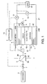
- FIG. 1 is a schematic diagram of a fuel cell power plant according to this invention.
- FIG. 2 is a diagram illustrating the effect on the performance of a fuel cell of impurity gas supplied to the anode of the fuel cell.
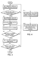
- FIG. 3 is a flowchart illustrating an anode effluent purging control routine which is executed by a controller according to this invention.
- FIG. 4 is a flowchart illustrating the main parts of an anode effluent purging control routine which is executed by a controller according to a second embodiment of this invention.
- FIG. 5 is similar to FIG. 3, but showing a third embodiment of this invention.
- FIG. 6 is similar to FIG. 3, but showing a fourth embodiment of this invention.
- FIG. 7 is a schematic diagram of a fuel cell power plant according to a fifth embodiment of this invention.
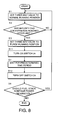
- FIG. 8 is a flowchart illustrating an anode effluent purging control routine which is executed by a controller according to the fifth embodiment of this invention.
- FIG. 9 is a schematic diagram of a fuel cell power plant according to a sixth embodiment of this invention.
- FIGs. 10A and 10B are flowcharts illustrating an anode effluent purging control routine executed by a controller according to the sixth embodiment of this invention.
- FIG. 11 is a schematic diagram of a fuel cell power plant according to a seventh embodiment of this invention.
- FIG. 12 is a schematic diagram of a fuel cell power plant according to an eighth embodiment of this invention.
- a fuel cell stack 1 of a fuel cell power plant is constituted by a stacked body of a large number of fuel cells connected in series.
- Each fuel cell is constituted by an electrolyte membrane 1B interposed between an anode 1A and a cathode 1C, and electrically conductive separators 1D and 1E disposed on the outsides of the anode 1A and cathode 1C.
- the fuel cell stack 1 in the drawing illustrates the constitution of a single fuel cell, but an actual fuel cell stack 1 is constituted by a stacked body in which these fuel cells are connected in series, and metallic terminals 20A and 20B for extracting an electric current are provided on the two ends of the stacked body.
- the fuel cell stack 1 generates power by means of the reaction of hydrogen in the hydrogen-rich gas which is supplied to the anode 1A and oxygen in the air which is supplied to the cathode 1C.
- Hydrogen-rich gas is produced by a reformer 2 and a hydrogen separator 3.
- the reformer 2 produces reformate gas containing a large amount of hydrogen by reforming ethanol or gasoline.
- the reformate gas flows into a first chamber 3A of the hydrogen separator 3 through a flow control valve 7.
- the hydrogen separator 3 is constituted by a first chamber 3A and a second chamber 3B which is partitioned from the first chamber 3A by a hydrogen permeable membrane 3C.
- the hydrogen permeable membrane 3C has a quality which allows only the permeation of small-dimension hydrogen molecules and disallows the permeation of other gas molecules with larger dimensions than hydrogen molecules. This type of hydrogen permeable membrane has become well-known through the aforementioned Tokkai 2001-23673.
- the hydrogen which passes through the hydrogen permeable membrane 3C to reach the second chamber 3B is supplied to the anode 1A of the fuel cell stack 1 as hydrogen-rich gas via a hydrogen supplying passage 9.
- the cathode 1C of the fuel cell stack 1 is supplied with air of a predetermined pressure from an air supplying passage 31.
- power is generated by the reaction of the hydrogen in the hydrogen-rich gas supplied to the anode 1A and the oxygen in the air supplied to the cathode 1C.
- anode effluent This gas shall be referred to as anode effluent.
- the anode 1A is supplied with a greater amount of hydrogen than is necessary for a power generation reaction, and therefore a large amount of hydrogen is still contained in the anode effluent.
- a recirculation passage 5 is connected to the anode effluent outlet of the fuel cell stack 1 via a three-way valve 4.
- the three-way valve 4 functions to switch between two positions, a purge running position for releasing the anode effluent into the atmosphere through an exhaust passage 6, and a normal running position for allowing the anode effluent to flow into the recirculation passage 5.
- the recirculation passage 5 is connected to the second chamber 3B of the hydrogen separator 3.
- a load 22 is connected to the terminals 20A and 20B of the fuel cell stack 1 via an electrical circuit 21.
- the load 22 comprises an alternating current motor and inverter, a secondary battery, auxiliaries, and a power management unit for controlling the power supply to these components.
- the switching of the three-way valve 4, the adjustment of the opening of the flow control valve 7, and the current supply to the load 22 are each controlled in accordance with signals output from a controller 10.
- the controller 10 is constituted by a microcomputer comprising a central processing unit (CPU), read-only memory (ROM), random access memory (RAM), and an input/output interface (I/O interface).
- the controller 10 may be constituted by a plurality of microcomputers.
- the hydrogen separating membrane 3C only allows the permeation of hydrogen, but in actuality pinholes tend to form during the manufacturing process of the hydrogen separating membrane 3C, and when pinholes occur, impurity gases in the reformate gas flow into the second chamber 3B in minute quantities.
- the hydrogen-rich gas separated by the separator 3 contains minute quantities of impurity gases such as carbon monoxide, carbon dioxide, and methane.
- impurity gases such as carbon monoxide, carbon dioxide, and methane.
- only hydrogen components are expended in the power generation reaction in the anode 1A, and hence, as anode effluent continues to recirculate through the recirculation passage 5, the concentration of the impurity gases contained in the circulating gas gradually rises.
- the curved line W1 illustrates the relationship between the current density and cell voltage of a single fuel cell in a full load state when pure hydrogen is supplied to the anode 1A.
- the current density is the value of the load current divided by the surface area of the reaction surface, of the fuel cell. If the fuel cell stack 1 operates continually while the anode effluent is recirculated, the impurity gases in the hydrogen-rich gas increase, and thus the fuel cell performance gradually deteriorates in the manner shown by the curved lines W2, W3, W4.
- the curved line W4 illustrates fuel cell performance when the impurity gas concentration has reached the upper limit of allowable concentration.
- the upper limit of allowable impurity gas concentration may also be defined by the amount of fuel consumed.
- carbon monoxide concentration poisons the electrode catalyst of the fuel cell stack 1, leading to a reduction in power generating efficiency.
- this poisoning is eradicated by supplying hydrogen-rich gas with a high degree of purity.
- the carbon monoxide concentration at a position of equilibrium between poisoning and eradication of poisoning may be determined experientially, and this concentration may be defined as the upper limit of allowable impurity gas concentration.
- the upper limit of allowable concentration is preferably determined by considering the values acquired by these various methods as a whole.
- the fuel cell voltage is maximum when the current density is zero and decreases as the current density rises.
- voltage decrease becomes pronounced in the region where the current density is high. This is because the amount of hydrogen supplied to the electrode surface is insufficient for a reaction, and hence the partial pressure of the hydrogen in the electrode decreases. This voltage decrease shall be referred to as a voltage decrease due to diffusion overpotential.
- the performance lines W1 through W4 in the drawing differ slightly depending on the temperature and pressure during operation of the fuel cell stack 1.
- the controller 10 switches the three-way valve 4 from the normal running position to the purge running position according to necessity such that the anode effluent is released into the atmosphere.
- the release of anode effluent into the atmosphere from the purge running position shall be referred to as purging.
- the controller 10 increases the power generating load on the fuel cell stack 1 as the anode effluent is purged such that all or substantially all of the hydrogen in the hydrogen-rich gas which is supplied to the anode 1A is expended in power generation.
- a mass flow meter 11 for detecting the mass flow rate of the hydrogen-rich gas supplied to the anode 1A, an ammeter 12 for detecting the output current of the fuel cell stack 1, and a voltmeter 13 for detecting the output voltage of the fuel cell stack 1 are respectively provided.
- the detection values thereof are respectively input into the controller 10 as signals.
- an anode effluent purging control routine which is executed by the controller 10 in order to perform this control will be described with reference to FIG. 3. This routine commences when the fuel cell stack becomes capable of power generation, and is executed continuously until operation of the fuel cell stack 1 ceases.
- the controller 10 sets the position of the three-way valve 4 to normal running position so that the fuel cell stack 1 generates power while recirculating the anode effluent. Also, the opening of the flow control valve 7 is set such that an amount of hydrogen-rich gas which exceeds a corresponding amount of current consumed by the load 22 is supplied to the anode 1A of the fuel cell stack 1.
- the current detected by the ammeter 12 is divided by the surface area of the reaction surface of each fuel cell constituting the fuel cell stack 1 to thereby calculate the current density. Further, by dividing the voltage detected by the voltmeter 13 by the number of fuel cells in the fuel cell stack 1, the output voltage per fuel cell is calculated. The current density and output voltage per fuel cell are then plotted on the diagram shown in FIG. 2. If the plotted point in FIG. 2 is positioned above the curved line W4 which corresponds to the upper limit of allowable concentration, it is determined that the concentration of impurity gas is less than the upper concentration limit. If the point is on or below the curved line W4, it is determined that the impurity gas concentration has reached or exceeded the upper limit of allowable concentration.
- a map, table or mathematical expressions corresponding to the curved line W4 are stored in advance in the memory of the controller 10.
- the controller 10 calculates the output voltage per fuel cell on the curved line W4 corresponding to the current density. If the output voltage per fuel cell determined from the voltage detected by the voltmeter 13 exceeds the output voltage per fuel cell on the curved line W4, it is determined that the impurity gas concentration has not reached the upper limit of allowable concentration. If the output voltage per fuel cell determined from the voltage detected by the voltmeter 13 does not exceed the output voltage per fuel cell on the curved line W4, it is determined that the impurity gas concentration has reached the upper limit of allowable concentration.
- a CO sensor may be provided on a part of the anode effluent recirculation path formed by the chamber 3B, the hydrogen supplying passage 9, the anode 1A, and the recirculation passage 5 such that the concentration of impurity gas in the hydrogen-rich gas may be directly detected.
- the controller 10 continues the power generation in the fuel cell stack 1 in normal running mode according to the step S1 and determination of the impurity gas concentration according to the step S2.
- the controller 10 switches the three-way valve 4 to the purge running position in a step S3 to commence the release of anode effluent into the atmosphere.
- a target output current value for the fuel cell stack 1 is set.
- This target output current value is set according to the following method on the basis of the mass flow rate of the hydrogen-rich gas detected by the mass flow meter 11.
- the hydrogen-rich gas is considered as pure hydrogen, when in fact impurity gases are contained in the hydrogen-rich gas.
- the proportion of impurity gas is approximately 1% and therefore minute in comparison with the proportion of hydrogen. It is therefore permissible to consider hydrogen-rich gas as approximately pure hydrogen when calculating the mass flow rate of hydrogen-rich gas.
- the power generating current of the fuel cell stack 1 for which all of the n mols/sec hydrogen is expended is logically expressed by 2 n F ampere.
- F is a Faraday constant.
- the controller 10 sets the target output current value as equal to this 2 n F ampere.
- the controller 10 operates the aforementioned power managing unit by means of signal output to the load 22 to increase the load current, or in other words the output current of the fuel cell stack 1, by a predetermined amount.
- step S6 the output current of the fuel cell stack 1 following this increase is compared with the target output current value.
- steps S6 and S7 is then repeated until the actual output current of the fuel cell stack 1, detected by the ammeter 12, reaches the target output current value.
- the controller 10 waits for a predetermined time period in a step S7. During this waiting period, the three-way valve 4 is held at the purge running position and the anode effluent is purged. After the predetermined time period has elapsed, in a step S8, the controller 10 determines if the fuel cell stack 1 should continue power generation.
- This determination is performed on the basis of signals from a key switch (not shown) which commands the fuel cell stack 1 to commence and halt operations.
- the controller 10 If the fuel cell stack 1 has not been ordered to halt operations, that is if the fuel cell stack 1 should continue to generate power, the controller 10 returns to the step S1 and repeats the aforementioned control. If the fuel cell stack 1 has been commanded to halt operations, that is if the fuel cell stack 1 should stop power generation, the controller 10 terminates the routine.
- the opening of the flow control valve 7 is calculated in another routine in accordance with the power generating current of the fuel cell stack 1 which is required by the load 22. Hence the opening of the flow control valve 7 during the execution of purging is not constant and the target output current value during purging is calculated from the hydrogen-rich gas mass flow rate detected by the mass flow meter 11.
- reformate gas is supplied to the hydrogen separator 3 in the same amount during purging as in the normal running position, and this reformate gas is supplied to the anode 1A via the hydrogen permeable membrane 3C as hydrogen-rich gas.
- This hydrogen-rich gas causes an action for scavenging residual impurity gas in the second chamber 3B, hydrogen supplying passage 9 and anode 1A.
- the output current of the fuel cell stack 1 during purging is increased beyond the output current during normal operations.
- the controller 10 it is preferable for the controller 10 to narrow the degree of opening of the flow control valve 7 upon commencement of purging so as to reduce the reformate gas flow rate.
- This embodiment corresponds to such a case, and the controller 10 executes processing for a step S1A in place of the step S1 in the first embodiment, and processing for a step S3A in place of the step S3. Processing in the other steps is identical to that of the first embodiment.
- step S1A the three-way valve 4 and flow control valve 7 are each set at the normal running position. If purging has been performed up to this point, this operation signifies returning the three -way valve 4 from the purge running position to the normal running position and returning the flow control valve 7 from the set opening for a purge operation to the opening during normal operations.
- the set opening for a purge operation is set smaller than the opening during normal operations.
- step S3A the three-way valve 4 is switched to the purge running position and the flow control valve 7 is narrowed to the set opening for a purge operation from the opening during normal operations.
- the target output current value calculated in the following step S4 becomes a constant value at all times. Therefore, in this case the mass flow meter 11 may be omitted and the calculation in the step S4 may also be omitted.
- the output current of the fuel cell stack 1 is reduced.
- the target output current value may become smaller than the actual output current value prior to narrowing of the degree of opening of the flow control valve 7.
- the target output current value is the maximum power generating current of the fuel cell stack 1 when the opening of the flow control valve 7 is narrowed, and by narrowing the opening of the flow control valve 7, the actual output current value falls to or below the target current value.
- the output current value of the fuel cell stack 1 is increased to the target current value in the steps S5 and S6.
- the mass flow meter 11 has been omitted from the constitution of the first embodiment in FIG. 1.
- the method of setting the target output current value during purging differs from the first embodiment.
- the controller 10 performs processing in a step S4A in place of step S4 in the first embodiment.
- the processing in the other steps is identical to that of the first embodiment.
- step S4A a value which is written to the ROM in advance on the basis of the fuel cell performance is applied as the target output current value.
- the target current value written in the ROM is set on the basis of the diffusion overpotential tendency of the fuel cell.
- a current value corresponding to the current density C1 at which the output voltage of the fuel cell drastically decreases due to the influence of diffusion overpotential is set as the target current value.
- the drastic decrease in the output voltage of the fuel cell signifies that insufficient hydrogen for a power generation reaction has been supplied to the anode 1A. In this state, substantially all of the supplied hydrogen is expended in the power generation reaction.
- hydrogen can be prevented from remaining in the anode effluent.
- lines W1 - W4 in FIG. 2 indicate performance in a full load state.
- the target output current value is set to a current value corresponding to the current density C2 at which the output voltage of the fuel cell according to the curved line W4A drastically decreases due to the influence of diffusion overpotential.
- the target output current value can be determined depending only on the opening of the flow control valve 7.
- the target output current value which is written into the ROM can be set as a fixed value.
- the processing of the step S4A simply consists of reading the value written in the ROM.
- a map of the target output current value altering in accordance with the opening of the flow control valve 7 is written into the ROM, and in the step S4A the map is referred to on the basis of the opening of the flow control valve 7 so as to dynamically set the target output current value.
- the mass flow meter 11 may be omitted, and hence the constitution of the device for achieving the object of the invention is simplified.
- FIG. 6 a fourth embodiment of this invention will be described.
- the mass flow meter 11 is also omitted in this embodiment, and as regards the processing of the controller 10, the step S4A of the third embodiment for setting the target output current value is also omitted. In place of the step S6 in the third embodiment, processing in a step S6A is performed. Processing in the other steps is identical to that of the third embodiment.
- a target output current value is not set.
- the output voltage per fuel cell is calculated from the output voltage detected by the voltmeter 13 and a determination is made as to whether this output voltage reaches 0.5 volts (V) or not.
- V 0.5 volts
- this value corresponds to the voltage when the output voltage of the fuel cell decreases drastically. It should be noted, however, that this value differs according to the fuel cell characteristic and is therefore set experientially in advance.
- This embodiment corresponds to the case in the third embodiment where the target current value is fixed at a value corresponding to the current density C1 .
- the constitution of the device for achieving the object of the invention may also be simplified according to this embodiment.
- the mass flow meter 11 from the first embodiment has been omitted and a short circuit 23 with a switch 24 is newly provided.
- the controller 10 increases the output current of the fuel cell stack 1 by operating the power managing unit of the load 22, whereas in this embodiment, the output current of the fuel cell stack 1 is increased by turning the switch 24 on and short-circuiting the short circuit 23.
- the increase range of the output current can be adjusted by connecting resistance in series with the switch 24.
- the controller 10 executes the routine shown in FIG. 8 instead of the routine of the first embodiment shown in FIG. 3.
- the steps S4 through S6 of the routine in FIG. 3 are omitted, and in place thereof a step S11 is provided. Also, a step S12 is provided between the steps S7 and S8.
- the processing in the steps S1 through S3 and the steps S7 and S8 is identical to that of the first embodiment.
- the controller 10 turns the switch 24 on by means of signal output.
- the switch 24 is turned on, the short circuit 23 is short-circuited and thus the output current of the fuel cell stack 1 increases.
- the controller 10 turns the switch 24 off in the step S12.
- the fuel cell stack 1 While waiting for the predetermined time period in the step S7, the fuel cell stack 1 consumes all of the hydrogen supplied to the anode 1A in order to cover the increased output current. When the surplus hydrogen is thus expended, the output voltage of the fuel cell stack 1 decreases and the output current also decreases. Accordingly, the switch 24 may be turned off by monitoring the decreases in the voltage and current rather than waiting for a predetermined time period.
- the exhaust passage 6 does not open onto the atmosphere but, as is illustrated in FIG. 9, is connected to the air supplying passage 31 for supplying air to the cathode 1C via an ejector 32.
- the output current of the fuel cell stack 1 is increased during purging, and hence the hydrogen concentration in the anode effluent decreases greatly. It is, however, possible for a small amount of hydrogen to remain in the anode effluent.
- the residual hydrogen in the anode effluent is oxidized by oxygen in the cathode 1C.
- the exhaust passage 6 of the first embodiment is merged with the air supplying passage 31 via the ejector 32. Further, the mass flow meter 11 of the first embodiment is omitted and the recirculation passage 5 is provided with a pressure sensor 33. The pressure detected by the pressure sensor 33 is input into the controller 10 as a signal. Otherwise, the constitution of the hardware relating to the purging of anode effluent is identical to that of the first embodiment.
- the controller 10 executes the routine shown in FIGs. 10A and 10B instead of the routine of FIG. 3 as the anode effluent purging control routine.
- the controller 10 sets the three -way valve 4 and flow control valve 7 to their respective normal running positions.
- step S2 a similar determination is made to that in the first embodiment as to whether the concentration of impurity gas in the hydrogen-rich gas has reached the upper limit of allowable concentration or not.
- the controller 10 repeats the processing of steps S1A and S2 until the impurity gas concentration reaches the upper limit of allowable concentration.
- the controller 10 closes the flow control valve 7 in a step S21.
- the controller 10 calculates the molar quantity of the residual hydrogen in the anode effluent recirculation path. This calculation is expressed by the product of the total capacity of the anode effluent recirculation path and the hydrogen partial pressure of the anode effluent recirculation path.
- the hydrogen partial pressure is estimated from the pressure in the anode effluent recirculation path which is detected by the pressure sensor 33 and the output voltage per fuel cell which is calculated from the voltage detected by the voltmeter 13 immediately prior to the execution of the step S21.
- the controller 10 calculates a target electric charge amount for the fuel cell stack 1 during a purge operation.
- the target electric charge amount is determined by multiplying the Faraday constant with the molar quantity of residual hydrogen.
- a next step S24 the controller 10 reads the target current value corresponding to the amount of time elapsed following the commencement of a purge operation from a time dependent map stored in the ROM in advance. This map is set experientially on the basis of changes in the output current of the fuel cell stack 1 during a purge operation.
- step S25 the actual output current of the fuel cell stack 1 detected by the ammeter 12 is time-integrated.
- step S26 the controller 10 operates the aforementioned power managing unit so that the output current of the fuel cell stack 1 becomes equal to the target current value.
- the controller 10 waits for a predetermined time period.
- a next step S27 the controller 10 determines whether the current integral value has reached the target electric charge amount. This determination indicates whether or not the residual hydrogen in the anode effluent recirculation path has been expended for power generation. If the current integral value of the residual hydrogen has not reached the target electric charge amount, the controller 10 repeats the processing in the steps S24 through S27.
- the controller 10 switches the three -way valve 4 to the purge running position in a step S28.
- the anode effluent then flows into the air supplying passage 31 via the ejector 32.
- the ejector 32 uses the air pressure of the air supplying passage 31 to ensure that the anode effluent is recirculated into the air supplying passage 31.
- a next step S29 the controller 10 waits for a predetermined time period.
- the controller 10 clears the integrated value of the current.
- step S8 a determination is made as to whether the fuel cell stack 1 should continue power generation. If the determination result is affirmative, the controller 10 returns to the step S1A and repeats the above control. If the determination result is negative, the controller 10 terminates the routine.
- substantially all of the hydrogen in the anode effluent is used for power generation until the controller 10 switches the three-way valve 4 to the purge running position in the step S28.
- impurity gases such as carbon monoxide, carbon dioxide, and methane.
- such anode effluent is mixed with the air which is supplied to the cathode 1C, and therefore these impurity gases are oxidized and discharged from the cathode 1C as harmless components. Even if hydrogen remains in the anode effluent, this hydrogen is oxidized in the cathode 1C and discharged as a noncombustible substance.
- the integral value of the output current of the fuel cell stack 1 is calculated and a determination is made on the basis of this current integral value as to whether the residual hydrogen in the anode effluent circulation path has been completely expended.
- All of the aforementioned first through sixth embodiments relate to a fuel cell power plant in which hydrogen-rich gas purified from reformate gas is supplied to the fuel cell stack 1.
- this invention may also be applied to a fuel cell power plant in which hydrogen purified in advance is supplied to the fuel cell stack 1.
- hydrogen purified in advance is supplied to the fuel cell stack 1.
- anode effluent is recirculated through the recirculation passage 5
- similar problems to a power plant which uses reformate gas arise in that the concentration of impurity gases in the hydrogen supplied to the fuel cell stack 1 increases as the power plant continues to operate.
- a seventh embodiment and eighth embodiment of this invention are embodiments in which this invention is applied to this type of fuel cell power plant.
- hydrogen stored in a hydrogen tank 41 is supplied to the anode 1A of the fuel cell stack 1 through the hydrogen supplying passage 9 at a constant pressure determined by a pressure regulator 42.
- the anode effluent which is discharged from the anode 1A is merged in the hydrogen supplying passage 9 via an identical three-way valve 4 and recirculation passage 5 which are identical to the first embodiment, and an ejector 43.
- the three-way valve 4 is switched to the purge running position and the output current of the fuel cell stack 1 is increased so that the hydrogen concentration in the purged anode effluent can be reduced.
- the fuel cell power plant according to this embodiment corresponds to that of the seventh embodiment where the anode effluent recirculation passage 5, the three-way valve 4 and the ejector 43 are omitted, and a shut-off valve 44 for the exhaust passage 6 provided instead.
- minute amounts of impurity gas leak out from the cathode 1C to the anode 1A via the electrolyte 1B. Minute amounts of impurity gas may also be contained in the hydrogen in the hydrogen tank 41.
- the shut-off valve 44 is closed and the controller 10 controls the flow control valve 7 such that all of the supplied hydrogen is used for generating power in the fuel cell stack 1.
- the controller 10 opens the shut-off valve 44 to release the anode effluent into the atmosphere.
- the hydrogen concentration in the purged anode effluent may be reduced by increasing the output current of the fuel cell stack 1.
- Tokugan 2002-38072 The contents of Tokugan 2002-38072, with a filing date of February 15, 2002 in Japan, are hereby incorporated by reference.
- the flow control valve 7 is provided between the reformer 2 and the hydrogen separator 3.
- the flow control valve 7 is not limited to this position and may be provided anywhere upstream of the anode 1A.
Landscapes
- Life Sciences & Earth Sciences (AREA)
- Engineering & Computer Science (AREA)
- Manufacturing & Machinery (AREA)
- Sustainable Development (AREA)
- Sustainable Energy (AREA)
- Chemical & Material Sciences (AREA)
- Chemical Kinetics & Catalysis (AREA)
- Electrochemistry (AREA)
- General Chemical & Material Sciences (AREA)
- Fuel Cell (AREA)
Applications Claiming Priority (2)
| Application Number | Priority Date | Filing Date | Title |
|---|---|---|---|
| JP2002038072A JP3972675B2 (ja) | 2002-02-15 | 2002-02-15 | 燃料電池システム |
| JP2002038072 | 2002-02-15 |
Publications (3)
| Publication Number | Publication Date |
|---|---|
| EP1339125A2 true EP1339125A2 (fr) | 2003-08-27 |
| EP1339125A3 EP1339125A3 (fr) | 2007-03-14 |
| EP1339125B1 EP1339125B1 (fr) | 2009-10-07 |
Family
ID=27655117
Family Applications (1)
| Application Number | Title | Priority Date | Filing Date |
|---|---|---|---|
| EP03000575A Expired - Lifetime EP1339125B1 (fr) | 2002-02-15 | 2003-01-13 | Contrôle de purge de l'effluent d'anode d'une pile à combustible |
Country Status (4)
| Country | Link |
|---|---|
| US (1) | US20030157383A1 (fr) |
| EP (1) | EP1339125B1 (fr) |
| JP (1) | JP3972675B2 (fr) |
| DE (1) | DE60329545D1 (fr) |
Cited By (18)
| Publication number | Priority date | Publication date | Assignee | Title |
|---|---|---|---|---|
| WO2004075328A2 (fr) * | 2003-02-20 | 2004-09-02 | Nissan Motor Co., Ltd. | Systeme de pile a combustible et son procede de commande |
| WO2004105165A2 (fr) * | 2003-05-21 | 2004-12-02 | Nissan Motor Co., Ltd. | Systeme de pile a combustible |
| WO2005048387A2 (fr) * | 2003-11-06 | 2005-05-26 | Snap-On Technologies, Inc. | Procede et appareil de service pour pile a combustible |
| WO2005101543A2 (fr) * | 2004-04-13 | 2005-10-27 | Toyota Jidosha Kabushiki Kaisha | Appareil et procede de commande de pile a combustible |
| FR2870389A1 (fr) * | 2004-05-11 | 2005-11-18 | Renault Sas | Dispositif d'alimentation en hydrogene d'une pile a combustible embarquee dans un vehicule |
| WO2005112159A1 (fr) * | 2004-05-14 | 2005-11-24 | Toyota Jidosha Kabushiki Kaisha | Systeme de pile a combustible |
| WO2006061194A1 (fr) * | 2004-12-08 | 2006-06-15 | Renault S.A.S. | Gestion de la purge dans les groupes electrogenes a piles a combustible |
| WO2007041474A1 (fr) * | 2005-09-30 | 2007-04-12 | Battelle Memorial Institute | Procede de fonctionnement d'un dispositif electrochimique comportant des commandes de debit massique et de parametre electrique |
| EP1821356A1 (fr) * | 2004-10-05 | 2007-08-22 | Nitto Denko Corporation | Passivation d'un acier exempte de chrome |
| US7282085B2 (en) | 2003-03-04 | 2007-10-16 | Toyota Jidosha Kabushiki Kaisha | Apparatus for hydrogen separation and fuel cell system |
| KR100811805B1 (ko) * | 2004-04-13 | 2008-03-10 | 도요다 지도샤 가부시끼가이샤 | 연료 전지용 제어 장치 및 제어 방법 |
| WO2008052577A1 (fr) * | 2006-10-31 | 2008-05-08 | Daimler Ag | Système d'alimentation de pile de cellules à combustible et procédé d'utilisation du système d'alimentation |
| FR2914786A1 (fr) * | 2007-04-06 | 2008-10-10 | Peugeot Citroen Automobiles Sa | Procede d'evaluation des debits des gaz circulant dans une boucle de recirculation en hydrogene d'une cellule de pile a combustible et dispositif associe |
| US7862954B2 (en) | 2003-11-19 | 2011-01-04 | Aquafairy Corporation | Fuel cell |
| WO2013093461A1 (fr) * | 2011-12-21 | 2013-06-27 | Intelligent Energy Limited | Dispositif de surveillance de la qualité d'hydrogène |
| US10862146B2 (en) | 2014-05-19 | 2020-12-08 | Intelligent Energy Limited | Apparatus for determining reactant purity |
| WO2022106159A1 (fr) * | 2020-11-19 | 2022-05-27 | Siemens Energy Global GmbH & Co. KG | Ensemble et procédé pour déterminer la pureté de l'hydrogène |
| DE102008028007B4 (de) | 2007-06-15 | 2022-11-17 | GM Global Technology Operations LLC (n. d. Ges. d. Staates Delaware) | Verfahren zum Anordnen einer Anodenentlüftung von einer Anodenseite eines ersten Teilstapels und eines zweiten Teilstapels |
Families Citing this family (45)
| Publication number | Priority date | Publication date | Assignee | Title |
|---|---|---|---|---|
| JP4469560B2 (ja) * | 2003-04-28 | 2010-05-26 | 本田技研工業株式会社 | 燃料電池システム |
| JP4882198B2 (ja) * | 2003-09-25 | 2012-02-22 | 日産自動車株式会社 | 燃料電池システム |
| JP2005129312A (ja) * | 2003-10-22 | 2005-05-19 | Denso Corp | 燃料電池の燃料供給装置 |
| JP4037355B2 (ja) | 2003-11-17 | 2008-01-23 | 本田技研工業株式会社 | 燃料電池の排出装置 |
| JP4648650B2 (ja) * | 2004-01-26 | 2011-03-09 | 株式会社豊田中央研究所 | 燃料電池システム |
| JP2005228481A (ja) * | 2004-02-10 | 2005-08-25 | Toyota Motor Corp | 燃料電池 |
| JP2005268056A (ja) * | 2004-03-18 | 2005-09-29 | Central Japan Railway Co | 水素供給システムおよび燃料電池システム |
| JP2005310653A (ja) * | 2004-04-23 | 2005-11-04 | Toyota Motor Corp | 燃料電池システム |
| JP4442429B2 (ja) * | 2004-05-14 | 2010-03-31 | トヨタ自動車株式会社 | 燃料電池システム |
| JP4458926B2 (ja) * | 2004-05-18 | 2010-04-28 | 三菱電機株式会社 | 電動パワーステアリング装置及びその制御方法 |
| JP4654618B2 (ja) * | 2004-06-24 | 2011-03-23 | トヨタ自動車株式会社 | 燃料電池システム |
| JP4953151B2 (ja) * | 2005-01-11 | 2012-06-13 | トヨタ自動車株式会社 | 燃料電池システム |
| JP4904719B2 (ja) * | 2005-05-25 | 2012-03-28 | トヨタ自動車株式会社 | 燃料電池システム、その制御方法及びそれを搭載した車両 |
| JP4894994B2 (ja) * | 2005-08-09 | 2012-03-14 | トヨタ自動車株式会社 | 燃料電池システム |
| JP4951892B2 (ja) * | 2005-08-19 | 2012-06-13 | コニカミノルタホールディングス株式会社 | 燃料電池システム |
| JP5425358B2 (ja) * | 2005-10-20 | 2014-02-26 | 株式会社日立製作所 | 固体高分子形燃料電池システムの停止方法及び固体高分子形燃料電池システム |
| US7855025B2 (en) * | 2005-11-21 | 2010-12-21 | Ford Global Technologies | Anode loop pressure control in PEM fuel cell system |
| US7654128B2 (en) | 2005-12-23 | 2010-02-02 | Ford Motor Company | Gas analyzing apparatus and method |
| JP2007066918A (ja) * | 2006-11-29 | 2007-03-15 | Nitto Denko Corp | 発電方法 |
| JP5092418B2 (ja) * | 2007-01-22 | 2012-12-05 | トヨタ自動車株式会社 | 燃料電池システム |
| JP5233126B2 (ja) * | 2007-02-05 | 2013-07-10 | トヨタ自動車株式会社 | 燃料電池システム |
| EP2132488A1 (fr) * | 2007-03-06 | 2009-12-16 | CeramTec AG | Procédé pour l'élimination écologique de mélanges air/solvant avec une installation à piles à combustible et une unité de récupération |
| JP5223242B2 (ja) * | 2007-05-25 | 2013-06-26 | トヨタ自動車株式会社 | 燃料電池システム |
| US8663448B2 (en) * | 2008-01-04 | 2014-03-04 | H2 Pump, Llc | Hydrogen furnace system and method |
| US8323841B2 (en) * | 2008-05-06 | 2012-12-04 | GM Global Technology Operations LLC | Anode loop observer for fuel cell systems |
| RU2472256C1 (ru) * | 2008-11-21 | 2013-01-10 | Ниссан Мотор Ко., Лтд. | Система топливного элемента и способ ее контроля |
| WO2012093991A1 (fr) * | 2011-01-03 | 2012-07-12 | Utc Power Corporation | Agencement de pile à combustible à recyclage d'énergie thermique |
| US9017451B2 (en) * | 2012-03-16 | 2015-04-28 | Membrane Technology And Research, Inc. | Membrane-based gas separation process using ejector-driven gas recycle |
| US20150174524A1 (en) * | 2012-03-16 | 2015-06-25 | Membrane Technology And Research, Inc. | Membrane-Based Gas Separation Process Using Ejector-Driven Gas Recycle |
| KR101543092B1 (ko) | 2013-07-08 | 2015-08-10 | 현대자동차주식회사 | 연료전지 시스템 및 그 운전방법 |
| US9843056B2 (en) * | 2013-10-08 | 2017-12-12 | Nissan Motor Co., Ltd. | Fuel cell system and method for controlling fuel cell system |
| KR101519764B1 (ko) * | 2013-12-30 | 2015-05-12 | 현대자동차주식회사 | 수소 저장 시스템의 퍼징 제어 장치 및 방법 |
| DE102014221321A1 (de) * | 2014-10-21 | 2016-04-21 | Volkswagen Ag | Brennstoffzellensystem sowie Verfahren zum Abschalten eines Brennstoffzellenstapels |
| KR101755936B1 (ko) * | 2015-12-11 | 2017-07-07 | 현대자동차주식회사 | 연료전지 시스템 및 제어 방법 |
| CA3117964C (fr) | 2016-04-21 | 2023-10-17 | Fuelcell Energy, Inc. | Post-traitement d'echappement d'anode de pile a combustible a carbonate fondu pour la capture de dioxyde de carbone |
| CN116435559A (zh) | 2016-04-29 | 2023-07-14 | 燃料电池能有限公司 | 甲烷化阳极废气以提高二氧化碳捕获 |
| JP7351607B2 (ja) * | 2018-09-03 | 2023-09-27 | トヨタ自動車株式会社 | 燃料電池システムおよび燃料ガス品質の判定方法 |
| JP7258144B2 (ja) | 2018-11-30 | 2023-04-14 | フュエルセル エナジー, インコーポレイテッド | Co2利用率を向上させて動作させる燃料電池のための改質触媒パターン |
| CN110676487B (zh) * | 2019-10-14 | 2022-07-29 | 国网山东省电力公司泰安供电公司 | 一种用于质子交换膜燃料电池的监测系统 |
| EP4118029A1 (fr) | 2020-03-11 | 2023-01-18 | Fuelcell Energy, Inc. | Unité de reformage de méthane à la vapeur pour la capture de carbone |
| CN111864232B (zh) * | 2020-08-03 | 2021-12-21 | 上海重塑能源科技有限公司 | 气体纯度检测方法及供氢系统的氢气纯度检测装置 |
| CN112687937B (zh) * | 2020-12-18 | 2022-09-06 | 上海神力科技有限公司 | 一种清理燃料电池电堆中异物的方法 |
| JP7484778B2 (ja) * | 2021-03-15 | 2024-05-16 | トヨタ自動車株式会社 | 燃料電池システム |
| CN113488678B (zh) * | 2021-06-30 | 2023-04-07 | 武汉理工大学 | 燃料电池汽车的供氢系统 |
| DE102023204074A1 (de) | 2023-05-03 | 2024-11-07 | Robert Bosch Gesellschaft mit beschränkter Haftung | Betriebsverfahren zum Vermeiden einer Anodenverarmung beim Betrieb eines Brennstoffzellensystems |
Citations (8)
| Publication number | Priority date | Publication date | Assignee | Title |
|---|---|---|---|---|
| EP0596366A1 (fr) * | 1992-11-05 | 1994-05-11 | Siemens Aktiengesellschaft | Procédé et dispositif pour évacuation de l'eau et des gaz inertes dans une batterie de piles à combustible |
| JPH06223859A (ja) * | 1993-01-28 | 1994-08-12 | Mazda Motor Corp | 燃料電池自動車 |
| EP0692835A2 (fr) * | 1994-07-13 | 1996-01-17 | Toyota Jidosha Kabushiki Kaisha | Générateur à piles à combustible et procédé d'opération |
| EP0911629A1 (fr) * | 1997-10-24 | 1999-04-28 | General Motors Corporation | Détecteur d'oxyde de carbone du type pile à combustible |
| EP1018774A1 (fr) * | 1999-01-05 | 2000-07-12 | L'air Liquide Société Anonyme pour l'étude et l'exploitation des procédés Georges Claude | Procédé de purge de circuit de gaz de pile à combustible, et dispositif de mise en oeuvre de ce procédé |
| JP2001023673A (ja) * | 1999-07-06 | 2001-01-26 | Daihatsu Motor Co Ltd | 燃料電池システム |
| DE10029468A1 (de) * | 1999-06-23 | 2001-04-12 | Daihatsu Motor Co Ltd | Brennstoffzellensystem |
| EP1120844A2 (fr) * | 2000-01-24 | 2001-08-01 | Toyota Jidosha Kabushiki Kaisha | Système pour production du gaz combustible pour piles à combustible |
Family Cites Families (4)
| Publication number | Priority date | Publication date | Assignee | Title |
|---|---|---|---|---|
| US4810595A (en) * | 1987-01-09 | 1989-03-07 | New Energy Development Organization | Molten carbonate fuel cell, and its operation control method |
| US4755439A (en) * | 1987-03-25 | 1988-07-05 | International Fuel Cells Corporation | Fuel cell configuration for contaminated fuel gases and method of using the same |
| US6375906B1 (en) * | 1999-08-12 | 2002-04-23 | Idatech, Llc | Steam reforming method and apparatus incorporating a hydrocarbon feedstock |
| US6299996B1 (en) * | 1999-09-24 | 2001-10-09 | Plug Power Inc. | Fuel cell system |
-
2002
- 2002-02-15 JP JP2002038072A patent/JP3972675B2/ja not_active Expired - Fee Related
-
2003
- 2003-01-13 DE DE60329545T patent/DE60329545D1/de not_active Expired - Lifetime
- 2003-01-13 EP EP03000575A patent/EP1339125B1/fr not_active Expired - Lifetime
- 2003-01-22 US US10/347,860 patent/US20030157383A1/en not_active Abandoned
Patent Citations (8)
| Publication number | Priority date | Publication date | Assignee | Title |
|---|---|---|---|---|
| EP0596366A1 (fr) * | 1992-11-05 | 1994-05-11 | Siemens Aktiengesellschaft | Procédé et dispositif pour évacuation de l'eau et des gaz inertes dans une batterie de piles à combustible |
| JPH06223859A (ja) * | 1993-01-28 | 1994-08-12 | Mazda Motor Corp | 燃料電池自動車 |
| EP0692835A2 (fr) * | 1994-07-13 | 1996-01-17 | Toyota Jidosha Kabushiki Kaisha | Générateur à piles à combustible et procédé d'opération |
| EP0911629A1 (fr) * | 1997-10-24 | 1999-04-28 | General Motors Corporation | Détecteur d'oxyde de carbone du type pile à combustible |
| EP1018774A1 (fr) * | 1999-01-05 | 2000-07-12 | L'air Liquide Société Anonyme pour l'étude et l'exploitation des procédés Georges Claude | Procédé de purge de circuit de gaz de pile à combustible, et dispositif de mise en oeuvre de ce procédé |
| DE10029468A1 (de) * | 1999-06-23 | 2001-04-12 | Daihatsu Motor Co Ltd | Brennstoffzellensystem |
| JP2001023673A (ja) * | 1999-07-06 | 2001-01-26 | Daihatsu Motor Co Ltd | 燃料電池システム |
| EP1120844A2 (fr) * | 2000-01-24 | 2001-08-01 | Toyota Jidosha Kabushiki Kaisha | Système pour production du gaz combustible pour piles à combustible |
Cited By (32)
| Publication number | Priority date | Publication date | Assignee | Title |
|---|---|---|---|---|
| WO2004075328A3 (fr) * | 2003-02-20 | 2005-03-03 | Nissan Motor | Systeme de pile a combustible et son procede de commande |
| WO2004075328A2 (fr) * | 2003-02-20 | 2004-09-02 | Nissan Motor Co., Ltd. | Systeme de pile a combustible et son procede de commande |
| DE102004010165B4 (de) * | 2003-03-04 | 2008-08-07 | Toyota Jidosha Kabushiki Kaisha, Toyota | Vorrichtung zur Wasserstoffseparation und Brennstoffzellensystem |
| US7282085B2 (en) | 2003-03-04 | 2007-10-16 | Toyota Jidosha Kabushiki Kaisha | Apparatus for hydrogen separation and fuel cell system |
| WO2004105165A2 (fr) * | 2003-05-21 | 2004-12-02 | Nissan Motor Co., Ltd. | Systeme de pile a combustible |
| WO2004105165A3 (fr) * | 2003-05-21 | 2005-02-24 | Nissan Motor | Systeme de pile a combustible |
| WO2005048387A3 (fr) * | 2003-11-06 | 2006-07-13 | Snap On Tech Inc | Procede et appareil de service pour pile a combustible |
| WO2005048387A2 (fr) * | 2003-11-06 | 2005-05-26 | Snap-On Technologies, Inc. | Procede et appareil de service pour pile a combustible |
| US7684880B2 (en) | 2003-11-06 | 2010-03-23 | Snap-On Technologies, Inc. | Fuel cells service method and apparatus |
| US7862954B2 (en) | 2003-11-19 | 2011-01-04 | Aquafairy Corporation | Fuel cell |
| WO2005101543A3 (fr) * | 2004-04-13 | 2006-05-18 | Toyota Motor Co Ltd | Appareil et procede de commande de pile a combustible |
| US8211581B2 (en) | 2004-04-13 | 2012-07-03 | Toyota Jidosha Kabushiki Kaisha | Control apparatus and control method for fuel cell |
| WO2005101543A2 (fr) * | 2004-04-13 | 2005-10-27 | Toyota Jidosha Kabushiki Kaisha | Appareil et procede de commande de pile a combustible |
| KR100811805B1 (ko) * | 2004-04-13 | 2008-03-10 | 도요다 지도샤 가부시끼가이샤 | 연료 전지용 제어 장치 및 제어 방법 |
| FR2870389A1 (fr) * | 2004-05-11 | 2005-11-18 | Renault Sas | Dispositif d'alimentation en hydrogene d'une pile a combustible embarquee dans un vehicule |
| CN1954449B (zh) * | 2004-05-14 | 2011-04-20 | 丰田自动车株式会社 | 燃料电池系统 |
| WO2005112159A1 (fr) * | 2004-05-14 | 2005-11-24 | Toyota Jidosha Kabushiki Kaisha | Systeme de pile a combustible |
| US7943265B2 (en) | 2004-05-14 | 2011-05-17 | Toyota Jidosha Kabushiki Kaisha | Fuel cell system |
| EP1821356A1 (fr) * | 2004-10-05 | 2007-08-22 | Nitto Denko Corporation | Passivation d'un acier exempte de chrome |
| EP1821356A4 (fr) * | 2004-10-05 | 2009-07-15 | Aquafairy Corp | Passivation d'un acier exempte de chrome |
| WO2006061194A1 (fr) * | 2004-12-08 | 2006-06-15 | Renault S.A.S. | Gestion de la purge dans les groupes electrogenes a piles a combustible |
| WO2007041474A1 (fr) * | 2005-09-30 | 2007-04-12 | Battelle Memorial Institute | Procede de fonctionnement d'un dispositif electrochimique comportant des commandes de debit massique et de parametre electrique |
| WO2008052577A1 (fr) * | 2006-10-31 | 2008-05-08 | Daimler Ag | Système d'alimentation de pile de cellules à combustible et procédé d'utilisation du système d'alimentation |
| CN101536226B (zh) * | 2006-10-31 | 2011-09-07 | 戴姆勒股份公司 | 用于燃料电池组的供给系统和用于操作该供给系统的方法 |
| US8481217B2 (en) | 2006-10-31 | 2013-07-09 | Daimler Ag | Method and apparatus for supplying input gases to a fuel cell stack |
| FR2914786A1 (fr) * | 2007-04-06 | 2008-10-10 | Peugeot Citroen Automobiles Sa | Procede d'evaluation des debits des gaz circulant dans une boucle de recirculation en hydrogene d'une cellule de pile a combustible et dispositif associe |
| DE102008028007B4 (de) | 2007-06-15 | 2022-11-17 | GM Global Technology Operations LLC (n. d. Ges. d. Staates Delaware) | Verfahren zum Anordnen einer Anodenentlüftung von einer Anodenseite eines ersten Teilstapels und eines zweiten Teilstapels |
| WO2013093461A1 (fr) * | 2011-12-21 | 2013-06-27 | Intelligent Energy Limited | Dispositif de surveillance de la qualité d'hydrogène |
| US10862146B2 (en) | 2014-05-19 | 2020-12-08 | Intelligent Energy Limited | Apparatus for determining reactant purity |
| GB2526287B (en) * | 2014-05-19 | 2021-09-22 | Intelligent Energy Ltd | Apparatus for determining reactant purity |
| US11362351B2 (en) | 2014-05-19 | 2022-06-14 | Intelligent Energy Limited | Apparatus for determining reactant purity |
| WO2022106159A1 (fr) * | 2020-11-19 | 2022-05-27 | Siemens Energy Global GmbH & Co. KG | Ensemble et procédé pour déterminer la pureté de l'hydrogène |
Also Published As
| Publication number | Publication date |
|---|---|
| EP1339125A3 (fr) | 2007-03-14 |
| JP2003243020A (ja) | 2003-08-29 |
| DE60329545D1 (de) | 2009-11-19 |
| US20030157383A1 (en) | 2003-08-21 |
| EP1339125B1 (fr) | 2009-10-07 |
| JP3972675B2 (ja) | 2007-09-05 |
Similar Documents
| Publication | Publication Date | Title |
|---|---|---|
| EP1339125B1 (fr) | Contrôle de purge de l'effluent d'anode d'une pile à combustible | |
| US7416800B2 (en) | Method and apparatus for a combined fuel cell and hydrogen purification system | |
| US6472090B1 (en) | Method and apparatus for operating an electrochemical fuel cell with periodic reactant starvation | |
| US8039154B2 (en) | Fuel cell system, method of starting fuel cell system | |
| US6841280B2 (en) | Fuel cell power plant | |
| WO2006054548A1 (fr) | Système de production d’énergie à pile à combustible, procédé et programme d’arrêt et de conservation | |
| US20050227137A1 (en) | Fuel-cell power plant | |
| JP5171423B2 (ja) | 燃料電池システム | |
| JP4523298B2 (ja) | 燃料電池システム及びその発電方法 | |
| JP7415981B2 (ja) | 燃料電池システム | |
| JP2002124290A (ja) | 燃料電池システム | |
| US7655336B2 (en) | Fuel-cell system | |
| US6821664B2 (en) | Method and apparatus for a combined fuel cell and hydrogen purification system | |
| US20080292928A1 (en) | Method for purging pem-type fuel cells | |
| JP5097016B2 (ja) | 燃料電池システム及び遮断弁の開閉状態判定方法 | |
| EP2056387B1 (fr) | Système de piles à combustible et procédé de purge correspondant | |
| JP5144152B2 (ja) | 放電システム | |
| JP2012209154A (ja) | 燃料電池システムを制御する制御装置 | |
| CN115020752A (zh) | 燃料电池系统 | |
| JPH06223856A (ja) | 燃料電池発電装置 | |
| US20190051917A1 (en) | Control device for fuel cell system | |
| JP7484778B2 (ja) | 燃料電池システム | |
| JP7578026B2 (ja) | 燃料電池システム | |
| JP7506786B2 (ja) | 燃料電池システム | |
| JPH08190929A (ja) | 燃料電池発電プラント |
Legal Events
| Date | Code | Title | Description |
|---|---|---|---|
| PUAI | Public reference made under article 153(3) epc to a published international application that has entered the european phase |
Free format text: ORIGINAL CODE: 0009012 |
|
| 17P | Request for examination filed |
Effective date: 20030113 |
|
| AK | Designated contracting states |
Designated state(s): AT BE BG CH CY CZ DE DK EE ES FI FR GB GR HU IE IT LI LU MC NL PT SE SI SK TR |
|
| AX | Request for extension of the european patent |
Extension state: AL LT LV MK RO |
|
| PUAL | Search report despatched |
Free format text: ORIGINAL CODE: 0009013 |
|
| AK | Designated contracting states |
Kind code of ref document: A3 Designated state(s): AT BE BG CH CY CZ DE DK EE ES FI FR GB GR HU IE IT LI LU MC NL PT SE SI SK TR |
|
| AX | Request for extension of the european patent |
Extension state: AL LT LV MK RO |
|
| 17Q | First examination report despatched |
Effective date: 20070521 |
|
| AKX | Designation fees paid |
Designated state(s): DE FR GB |
|
| GRAP | Despatch of communication of intention to grant a patent |
Free format text: ORIGINAL CODE: EPIDOSNIGR1 |
|
| GRAS | Grant fee paid |
Free format text: ORIGINAL CODE: EPIDOSNIGR3 |
|
| GRAA | (expected) grant |
Free format text: ORIGINAL CODE: 0009210 |
|
| AK | Designated contracting states |
Kind code of ref document: B1 Designated state(s): DE FR GB |
|
| REG | Reference to a national code |
Ref country code: GB Ref legal event code: FG4D |
|
| REF | Corresponds to: |
Ref document number: 60329545 Country of ref document: DE Date of ref document: 20091119 Kind code of ref document: P |
|
| PGFP | Annual fee paid to national office [announced via postgrant information from national office to epo] |
Ref country code: FR Payment date: 20100209 Year of fee payment: 8 |
|
| PGFP | Annual fee paid to national office [announced via postgrant information from national office to epo] |
Ref country code: GB Payment date: 20100121 Year of fee payment: 8 Ref country code: DE Payment date: 20100129 Year of fee payment: 8 |
|
| PLBE | No opposition filed within time limit |
Free format text: ORIGINAL CODE: 0009261 |
|
| STAA | Information on the status of an ep patent application or granted ep patent |
Free format text: STATUS: NO OPPOSITION FILED WITHIN TIME LIMIT |
|
| 26N | No opposition filed |
Effective date: 20100708 |
|
| GBPC | Gb: european patent ceased through non-payment of renewal fee |
Effective date: 20110113 |
|
| REG | Reference to a national code |
Ref country code: FR Ref legal event code: ST Effective date: 20110930 |
|
| PG25 | Lapsed in a contracting state [announced via postgrant information from national office to epo] |
Ref country code: FR Free format text: LAPSE BECAUSE OF NON-PAYMENT OF DUE FEES Effective date: 20110131 |
|
| PG25 | Lapsed in a contracting state [announced via postgrant information from national office to epo] |
Ref country code: GB Free format text: LAPSE BECAUSE OF NON-PAYMENT OF DUE FEES Effective date: 20110113 |
|
| REG | Reference to a national code |
Ref country code: DE Ref legal event code: R119 Ref document number: 60329545 Country of ref document: DE Effective date: 20110802 |
|
| PG25 | Lapsed in a contracting state [announced via postgrant information from national office to epo] |
Ref country code: DE Free format text: LAPSE BECAUSE OF NON-PAYMENT OF DUE FEES Effective date: 20110802 |