EP1336302B1 - Engine bearing inspection system - Google Patents
Engine bearing inspection system Download PDFInfo
- Publication number
- EP1336302B1 EP1336302B1 EP01966081A EP01966081A EP1336302B1 EP 1336302 B1 EP1336302 B1 EP 1336302B1 EP 01966081 A EP01966081 A EP 01966081A EP 01966081 A EP01966081 A EP 01966081A EP 1336302 B1 EP1336302 B1 EP 1336302B1
- Authority
- EP
- European Patent Office
- Prior art keywords
- mirror
- scanning
- stationary
- scanning mirror
- light line
- Prior art date
- Legal status (The legal status is an assumption and is not a legal conclusion. Google has not performed a legal analysis and makes no representation as to the accuracy of the status listed.)
- Expired - Lifetime
Links
- 238000007689 inspection Methods 0.000 title claims abstract description 27
- 230000007547 defect Effects 0.000 claims description 9
- 239000012535 impurity Substances 0.000 claims description 8
- 238000000034 method Methods 0.000 abstract description 9
- 238000003384 imaging method Methods 0.000 description 5
- 238000013459 approach Methods 0.000 description 3
- 238000010586 diagram Methods 0.000 description 2
- 238000005516 engineering process Methods 0.000 description 2
- 238000004519 manufacturing process Methods 0.000 description 2
- 238000002360 preparation method Methods 0.000 description 2
- 238000004458 analytical method Methods 0.000 description 1
- 238000006243 chemical reaction Methods 0.000 description 1
- 238000002485 combustion reaction Methods 0.000 description 1
- 230000003247 decreasing effect Effects 0.000 description 1
- 239000000428 dust Substances 0.000 description 1
- 230000000694 effects Effects 0.000 description 1
- 230000008030 elimination Effects 0.000 description 1
- 238000003379 elimination reaction Methods 0.000 description 1
- 238000011156 evaluation Methods 0.000 description 1
- 239000013307 optical fiber Substances 0.000 description 1
- 230000002028 premature Effects 0.000 description 1
- 230000003252 repetitive effect Effects 0.000 description 1
Images

Classifications
-
- G—PHYSICS
- G01—MEASURING; TESTING
- G01N—INVESTIGATING OR ANALYSING MATERIALS BY DETERMINING THEIR CHEMICAL OR PHYSICAL PROPERTIES
- G01N21/00—Investigating or analysing materials by the use of optical means, i.e. using sub-millimetre waves, infrared, visible or ultraviolet light
- G01N21/84—Systems specially adapted for particular applications
- G01N21/88—Investigating the presence of flaws or contamination
- G01N21/8806—Specially adapted optical and illumination features
Definitions
- the present invention relates generally to an inspection system, and more particularly, to an engine bearing inspection system and to a method to inspect engine bearings.
- ID surfaces In motor vehicles, engine bearings serve to withstand the immense mechanical loads generated by crankshaft movement and to protect the crankshaft journals from physically contacting the engine block. Because of the tremendous loads on the inner diameter (ID) surface of these engine bearings, the ID surfaces must remain free from impurities and defects, such as dust, scratches and chips at all times, including during their own manufacturing process.
- bearing manufacturers inspect the ID surfaces for defects and impurities with human inspectors. Because of high production demands, manufacturers typically produce eighty bearings every minute. Because of this high throughput, it is not possible for the human inspectors to inspect every bearing for impurities or defects. To increase the numbers of bearings inspected, bearing manufacturers have attempted to inspect the ID surfaces with imaging technology. Conventional inspection approaches have shortcomings.
- One approach taken to inspect an inside diameter surface in the context of a can includes using at least three cameras to view the entire ID surface as seen by reference to U.S. Patent No. 5,699,152 issued to Fedor et al .
- the expense incurred in using at least three cameras exemplifies an obvious flaw with the approach taken in Fedor et al.
- Another flaw caused by using multiple cameras (such as in Fedor et al.), in general, involves the generation of internal reflections. Internal reflections are caused by the use of multiple light sources in the imaging process that generate internal reflections, for example within the concave-shaped bearing.
- the internal reflections in turn, generate undesirable dark strips on the resulting images of the ID surface. The dark strips will prevent the imaging system from detecting impurities or defects located on these obscured portions of the ID surface images.
- Another imaging technology method used to inspect ID surfaces utilizes a single camera. Yet in order to view the bearing in its entirety, either the camera or the bearing under inspection must move to perform a complete scan of the entire surface ID. Moving the bearing slows throughput because extra time must be allotted for the bearing's motion and the extra movement exposes the bearing to an increased risk of damage. Likewise, moving the camera to scan the bearing also slows throughput because extra time must be allotted for the camera's motion. Furthermore, in order for the camera to move, the system requires long cables to power and operate the camera. These long cables generate electromagnetic interference that reduces the image quality of the inspection system. Also, the repetitive movement of the camera causes premature wear or breakage of the camera cables. This wear or breakage usually results in the costly replacement of the camera cables.
- US A-1 983 827 discloses a linescan apparatus for detecting defects on e.g., a circuit board, keyboard or other product.
- a linescan apparatus for detecting defects on e.g., a circuit board, keyboard or other product.
- the linescan apparatus comprising a laser light source 5 emitting a beam 6a, and a beam deflecting portion 101 for deflecting the beam introduced through mirrors 8a, 8b, and 8c so as to produce a linescan laser beam via a polygon mirror 7 which is rotated by a drive portion 102.
- the apparatus further comprises a rotary position encoder 106, a carrying portion 3 to move the product at a given speed.
- Polygon mirror 7 rotates at substantially constant speed scanning the beam over the product on carrying portion 3 which moves in the direction shown by the arrow 4 so that the product is scanned two-dimensionally.
- the output of the position signal processing circuit 14a is sent to the evaluation circuit 15a.
- One object of the present invention is to provide a solution to one or more of the above mentioned problems.
- One advantage of the present invention is that only one camera is needed to acquire the image beam of the inside diameter (ID) surface of a component under inspection such as an engine bearing.
- Another advantage of the present invention is that the camera remains stationary, thereby eliminating the possibility of excessive wear, breakage and tangling of the camera cables.
- Another advantage of the present invention is the elimination of internal reflection interference in the resulting image, compared to conventional multi-camera, multi-light source arrangements.
- Another advantage of the present invention is that the component under inspection remains stationary throughout the scanning process, thus reducing the possibility of damaging the component by excessive movement.
- Still another advantage of the present invention is that an increased percentage of engine bearings can be inspected for impurities and defects without decreasing throughput.
- an inspection - system for inspecting an inside diameter (ID) surface of a component comprising:
- the system may be used to view an image of an inside diameter (ID) surface of a component, such as an engine bearing.
- ID inside diameter
- a component such as an engine bearing.
- the first and second stationary mirrors may be symmetric about said main viewing axis.
- the first and second stationary mirrors may be configured to direct said image beam of said component to said first mirror and said beam splitter.
- the system may further include a control device configured to control and coordinate movements of said first mirror and said scanning mirror.
- the line scan camera may have a line of sight coincident with a main viewing axis.
- the respective rotating axes of said first mirror and said scanning mirror may be parallel.
- the system may further include a light line generator configured to generate said source light beam, said source light beam comprising a light line.
- the light line generator may be centered about a main viewing axis.
- a rotating axis of one of said first mirror and said scanning mirror may be parallel to said source light beam.
- the optics may further include a beam splitter configured to facilitate the overlapping of the path taken by the source light beam and the path taken by the image beam.
- the system may further include a lens disposed between said line scan camera and said beam splitter. The lens may have a principal axis that is coincident with said main viewing axis.
- the system may further include means for recording said image beam.
- the system may further including means for analyzing said image beam for predetermined characteristics wherein said predetermined characteristics include impurities and defects on the inside diameter (ID) surface and type and shape of the component.
- predetermined characteristics include impurities and defects on the inside diameter (ID) surface and type and shape of the component.
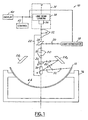
- Figure 1 illustrates an inspection system 10 according to the present invention.
- System 10 in one embodiment, is particularly suited for inspection of components used in an automotive environment.
- the present invention may also be applied to various other uses that may require an inspection system, including inspection of other parts having an inside diameter (ID) surface.
- ID inside diameter
- System 10 is configured for inspecting a component having an inside diameter (ID surface).
- such component comprises an engine bearing, particularly one-half of a split type main bearing.
- system 10 may include one representation of many possible systems to inspect an engine bearing.
- the component to be inspected such as engine bearing 12 (best shown in Figure 2 ), may be placed symmetrically with respect to a viewing axis 14 on a stationary mounting platform 16.
- engine bearings are merely one type of many possible components that can be inspected using system 10.
- engine bearing 12 can be positioned asymmetrically relative to axis 14, depending upon which portion of engine bearing 12 requires inspection.
- Figure 1 also depicts a light line generator 18 configured to produce a light line 20, and an optics system 22.
- Optics system 22 includes a beam splitter 24, a pivoting mirror 26, a pair of stationary mirrors 28 1 , 28 2 that are symmetrically positioned about viewing axis 14, and a scanning mirror 30.
- Figure 1 further illustrates an image beam 32, an image acquisition means 34 comprising a lens 36 and a stationary line scan camera 38, a display monitor 40 and a control module 42 that houses the logic to drive generator 18 and control various components of optics system 22.
- Axis C is the cylindrical axis of engine bearing 12.
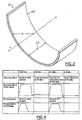
- An engine bearing ID surface 44 is the surface of engine bearing 12 that is scanned by system 10 for imperfections such as, but not limited to, scratches, nicks, chips, lint or dirt.
- Light line 20 is also shown in diagrammatic fashion.
- generator 18 is configured to produce light line 20 for illuminating the ID surface 44 of bearing 12.
- generator 18 is controlled by control module 42 to activate and create light line 20.
- generator 18 may include one of a plurality of light sources that can be used in conjunction with system 10. Types of light sources include, but are not limited to, laser, optical fiber or focused light. The type of light used depends upon, among other factors, the type and shape of the component being inspected.
- Generator 18 is positioned in a manner such that light line 20 is directed to beam splitter 24.
- Optics system 22 is configured generally to direct a source light beam from generator 18 to the ID surface 44 wherein the image beam 32 is produced.
- Optics 22 includes a beam splitter 24 that is centered on axis 14 wherein axis 14 coincides with the center of engine bearing 12. Once light line 20 reaches beam splitter 24, light line 20 will be directed to pivoting mirror 26.
- Pivoting mirror 26 is centered on axis 14. Pivoting mirror 26 is moveable between a first position and a second position. In the illustrated embodiment, controller 42 is configured to move pivoting mirror 26 to the first position to scan a first half ( i . e ., the right hand side) of the bearing, and, to further move mirror 26 to its second position to scan the other half of ID surface 44 ( i . e ., the left hand side). It should be appreciated that pivoting mirror 26 may comprise one of a plurality of highly reflective surfaces known to those of ordinary skill.
- Stationary mirror 28 1 and mirror 28 2 can be any one of a plurality of highly reflective surfaces known to those of ordinary skill.
- Scanning mirror 30 can be substituted with any one of a plurality of highly reflective surfaces, as one skilled in the art will realize.
- Scanning mirror 30, in a preferred embodiment, is positioned such that its rotating axis A is parallel to the rotating axis of pivoting mirror 26, namely rotating axis B.
- Scanning mirror 30 is moveable so as to sweep from a first start orientation to a first stop orientation, and to further sweep from a second start orientation to a second stop orientation.
- Scanning mirror 30 has an axis of rotation, designated "A,” that is preferably coincident with the cylindrical axis " C " of the component ( e.g ., bearing 12). This will be described in greater detail below.
- the pivoting mirror 26, when in the first position, is configured to direct the source light beam (i.e ., light line 20) to the scanning mirror 30 by way of first stationary mirror 28 1 .
- Scanning mirror 30 is configured to scan the ID surface 44 using the source light beam, namely light line 20, when the scanning mirror is moved via controller 42 from the above-mentioned first start orientation through to the above-mentioned first stop orientation. In one embodiment, this action scans one-half of the bearing.
- Pivoting mirror 26, in its second position is configured to direct the source light beam, namely light line 20, to scanning mirror 30 via second stationary mirror 28 2 .
- the scanning mirror 30 is configured to scan the ID surface 44 when it is moved under control of controller 42 from its second start orientation through to its second stop orientation using the source light beam.
- the twelve o'clock position may be taken as the o-degree reference, with increasing degree values to be taken in the clockwise (CW) direction. Pivoting mirror 26 initially faces about 45-degrees; however, this direction can be altered as needed.
- scanning mirror 30 is initially positioned in a first start orientation, which is at 81 degrees in the present embodiment. That is, the mirror is positioned so that a light line 20 is redirected to about an 81 degree position, relative to a 12 o'clock position being 0 degrees.
- the first start orientation thus provides a starting point for scanning mirror 30 to scan the right side of ID surface 44.
- controller causes mirror 26 and mirror 30 to assume the positions/orientations described above, it causes generator to be activated and produce light line 20.
- light line 20 After light line 20 reaches pivoting mirror 26, it will be directed to stationary mirror 28 1 . From stationary mirror 28 1 , light line 20 will travel to scanning mirror 30. Light line 20, when it leaves scanning mirror 30, will travel to and contact the engine bearing inside diameter (ID) surface 44 at approximately 90-degrees.
- ID engine bearing inside diameter
- scanning mirror 30 While scanning mirror 30 is controlled to rotate clockwise, it will redirect light line 20 in a clockwise scanning motion.
- an image beam 32 of ID surface 44 is generated. Image beam 32 initially will retrace light line's 20 path. Image beam 32 travels from the ID surface 44 and strikes scanning mirror 30. Scanning mirror 30 guides image beam 32 to stationary mirror 28 1 , which in turn directs image beam 32 to pivoting mirror 26.
- beam splitter 24 Unlike light line 20, however, beam splitter 24 will not divert image beam 32. Instead, image beam 32 will pass through beam splitter 24 and into lens 36. Lens 36 can magnify and focus image beam 32 if needed.
- image beam 32 will travel to stationary camera 38, where it may be acquired, and, thereafter processed by either (i) image processing software in control module 42 or (ii) by an operator using display monitor 40 and be recorded for later analysis. Both lens 36 and stationary camera 38 may be centered on axis 14. Further, one skilled in the art will realize that recording can be accomplished by many methods including, but not limited to, electronically or magnetically.
- Scanning mirror 30 will continue rotating clockwise under control of control module 42 until reaching the first stop orientation. In the first stop orientation, light line 20 is directed by mirror 30 to the 180-degree reference. The scanning mirror 30 itself is rotated about 47 degrees.
- Controller 42 controls the initialization of optics system 22 ( e . g ., to initial or start orientations) the light generator 18, and image acquisitions means 34. To effect scanning of the left side as viewed in Figures 1 and 3 , controller 42 causes pivoting mirror 26 to rotate from its first position ( i.e ., the 45-degree position) to its second position ( i . e ., 315-degree position).
- Controller 42 will further cause scanning mirror 30 to rotate from its prior position where it directed light line 20 to the 180-degree position ( i . e ., where it finished its first scan) to a position where it will direct light line 20 to an approximately 284-degree position. This will mark the second start orientation for scanning the remainder of bearing 12.
- Control module 42 houses the logic necessary to command the operation of motors used in moving mirrors 26 and 30. It takes system 10 approximately 0.25 seconds to move scanning mirror 30 and pivoting mirror 26 into their initial start positions at 81-degrees and 45-degrees respectively; however, one skilled in the art will realize that the amount of time system 10 takes to initialize scanning mirror 30 and pivoting mirror 26 depends upon other system components, such as the type of motor used. During this time, the rpm profiles of scanning mirror 30 and pivoting mirror 26 reach their first peak at approximately 200 rpm.
- rpm values can be used in conjunction with system 10 as dictated by the components used.
- the rpm output of pivoting mirror 26 is zero because pivoting mirror 26 is stationary during scanning.
- the speed of scanning mirror 30 drops down to 40 rpm to complete the scanning motion.
- the scan of the right side of engine bearing 12 takes approximately 0.2 seconds, yet one skilled in the art will realize that this value depends upon the components used and also can be altered as needed.
- the improvement occasioned by the present invention results from keeping both the camera and the component stationary. This allows the improved scanning speed referred to above.
- scanning mirror 30 and pivoting mirror 26 are initialized once again in preparation for the scan of the left side of engine bearing 12.
- the motors will place scanning mirror 30 in the 284-degree position and pivoting mirror 26 in the 315-degree position the respective start orientations for the left hand side scan.
- the rpm values once again achieve their maximum value at approximately 200 rpm. From this initial position, the rpm value for pivoting mirror 26 again drops to zero because pivoting mirror 26 does not move during the scanning process. Similarly, the rpm value for scanning mirror 30 drops to 40 rpm during the scan of the left side of engine bearing 12. In 0.2 seconds, the scan of the left side of engine bearing 12 is complete.
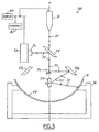
- an alternative embodiment of an engine bearing inspection system designated 110 is presented. Instead of being stationed directly above engine bearing 12, stationary camera 38 and lens 36 are positioned off to the side while generator 18 assumes the position above engine bearing 12.
- light line 20 will flow through beam splitter 24 onto pivoting mirror 26. From pivoting mirror 26, light line 20 will be directed as described in reference to Figures 1-3 above.
- Image beam 32 also will follow the same general trajectory as described in reference to Figures 1 and 2 above, except that beam splitter 24 will direct image beam 32 into lens 36, where it then travels to stationary camera 38.
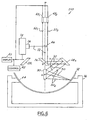
- a first mirror 46 replaces beam splitter 24.
- two light line generators 48 1 , 48 2 are symmetrically mounted above first mirror 46 such that the generated light lines 50 1 , 50 2 do not contact the first mirror 46.
- Light lines 50 1 , 50 2 will flow through first mirror 46 and contact pivoting mirror 26. From pivoting mirror 26, light lines 50 1 , 50 2 will proceed as described in reference to Figures 1 and 2 above.
- Image beam 32 will also be directed as described in reference to Figures 1 and 2 above except that instead of bypassing beam splitter 24, image beam 32 will be guided by first mirror 46 into the lens 36.
- the source light path and the image path can be rearranged so that the specific example values provided above may vary.
- the source lighting and imaging paths may be slightly different so that the pivoting mirror 26 faces a 42.12 degree direction and a 317.88 degree direction, instead of a 45 degree direction and 315 degree direction, respectively, in preparation for right hand side and left hand side scans of bearing 12.
- scanning mirror 30 is located at, and rotates with respect to a cylindrical axis, or best fitted cylindrical axis, of a full, semi, partial, or near cylindrical part surface being inspected.
- the cylindrical axis C of the bearing 12 (or best fit axis of any particular part) is substantially coincident with the axis of rotation A of the scanning mirror 30.
- the path taken by the source light beam and the path taken by the image beam are substantially identical from the ID surface 44 all the way to beam splitter 24.
- those of ordinary skill in the art will appreciate that there exists no perfect cylindrical surfaces and reasonable tolerances should be given to the meanings of "identical” and "perpendicular,” as described herein.
- the invented system wherever necessary, can be reduced to scan a portion of an engine bearing, or a part of the like, with only one of the stationary mirrors, the scanning mirror. In this case, the light will be directed directly from the beam splitter to the stationary mirror, without passing through the pivoting mirror.
Landscapes
- Physics & Mathematics (AREA)
- Health & Medical Sciences (AREA)
- Life Sciences & Earth Sciences (AREA)
- Chemical & Material Sciences (AREA)
- Analytical Chemistry (AREA)
- Biochemistry (AREA)
- General Health & Medical Sciences (AREA)
- General Physics & Mathematics (AREA)
- Immunology (AREA)
- Pathology (AREA)
- Investigating Materials By The Use Of Optical Means Adapted For Particular Applications (AREA)
- Length Measuring Devices By Optical Means (AREA)
- Mechanical Optical Scanning Systems (AREA)
- Testing Of Engines (AREA)
- Manufacture Of Motors, Generators (AREA)
- Testing Of Balance (AREA)
Applications Claiming Priority (5)
| Application Number | Priority Date | Filing Date | Title |
|---|---|---|---|
| US934151 | 1986-11-24 | ||
| US22753800P | 2000-08-24 | 2000-08-24 | |
| US227538P | 2000-08-24 | ||
| US09/934,151 US6661506B2 (en) | 2000-08-24 | 2001-08-21 | Engine bearing inspection system |
| PCT/US2001/026222 WO2002016787A2 (en) | 2000-08-24 | 2001-08-22 | Engine bearing inspection system |
Publications (3)
| Publication Number | Publication Date |
|---|---|
| EP1336302A2 EP1336302A2 (en) | 2003-08-20 |
| EP1336302A4 EP1336302A4 (en) | 2006-01-11 |
| EP1336302B1 true EP1336302B1 (en) | 2009-03-11 |
Family
ID=26921527
Family Applications (1)
| Application Number | Title | Priority Date | Filing Date |
|---|---|---|---|
| EP01966081A Expired - Lifetime EP1336302B1 (en) | 2000-08-24 | 2001-08-22 | Engine bearing inspection system |
Country Status (7)
| Country | Link |
|---|---|
| US (1) | US6661506B2 (enExample) |
| EP (1) | EP1336302B1 (enExample) |
| JP (1) | JP3905475B2 (enExample) |
| AT (1) | ATE425451T1 (enExample) |
| AU (1) | AU2001286623A1 (enExample) |
| DE (1) | DE60137959D1 (enExample) |
| WO (1) | WO2002016787A2 (enExample) |
Families Citing this family (5)
| Publication number | Priority date | Publication date | Assignee | Title |
|---|---|---|---|---|
| WO2003007879A2 (en) * | 2001-07-16 | 2003-01-30 | Depuy Products, Inc. | Cartilage repair and regeneration scaffold and method |
| WO2011112675A1 (en) * | 2010-03-09 | 2011-09-15 | Federal-Mogul Corporation | Bore inspection system and method of inspection therewith |
| CN107436307A (zh) * | 2017-07-07 | 2017-12-05 | 柳州杰诺瑞汽车电器系统制造有限公司 | 视觉自动检测系统及其检测方法 |
| SG11202101620UA (en) * | 2018-08-21 | 2021-03-30 | Waertsilae Finland Oy | Method and apparatus for plain bearing crush height measurement |
| CN110470472B (zh) * | 2019-09-20 | 2020-11-17 | 台州浙盛轴承科技有限公司 | 一种轴承内圈磨损程度检测设备 |
Family Cites Families (48)
| Publication number | Priority date | Publication date | Assignee | Title |
|---|---|---|---|---|
| GB1270651A (en) * | 1968-04-01 | 1972-04-12 | Hawker Siddeley Dynamics Ltd | Improvements in or relating to optical scanning equipment |
| US3761186A (en) * | 1972-01-17 | 1973-09-25 | Itt | Apparatus for optically inspecting the condition of a surface having known variations in the condition |
| US4561731A (en) | 1980-03-10 | 1985-12-31 | Kley Victor B | Electronic illumination control |
| IT1130474B (it) | 1980-05-28 | 1986-06-11 | Fiat Auto Spa | Procedimento e dispositivo per l ispezione ed il controllo della superficie interna di un pezzo cilindrico cavo che ha subito una lavorazione meccanica |
| US4622462A (en) | 1981-06-11 | 1986-11-11 | Mts Vektronics Corporation | Method and apparatus for three-dimensional scanning |
| JPS58105517U (ja) | 1982-01-07 | 1983-07-18 | 住友電気工業株式会社 | 管路用監視装置 |
| US4527055A (en) * | 1982-11-15 | 1985-07-02 | Honeywell Inc. | Apparatus for selectively viewing either of two scenes of interest |
| JPS60229006A (ja) * | 1984-04-27 | 1985-11-14 | Nec Corp | 回転多面鏡の面倒れ角補正装置 |
| US4750045A (en) * | 1985-08-15 | 1988-06-07 | Fuji Photo Film Co., Ltd. | Light beam scanning system |
| JPS6292572A (ja) * | 1985-10-17 | 1987-04-28 | Fuji Photo Film Co Ltd | 光ビ−ム走査装置 |
| US4886975A (en) | 1986-02-14 | 1989-12-12 | Canon Kabushiki Kaisha | Surface examining apparatus for detecting the presence of foreign particles on two or more surfaces |
| US4725883A (en) | 1986-07-18 | 1988-02-16 | Westinghouse Electric Corp. | Optical profilometry system for tubular products |
| GB8626812D0 (en) * | 1986-11-10 | 1986-12-10 | Sira Ltd | Surface inspection |
| US4849643A (en) | 1987-09-18 | 1989-07-18 | Eaton Leonard Technologies | Optical probe with overlapping detection fields |
| US5008555A (en) | 1988-04-08 | 1991-04-16 | Eaton Leonard Technologies, Inc. | Optical probe with overlapping detection fields |
| FR2631697B1 (fr) | 1988-05-17 | 1991-07-26 | Hispano Suiza Sa | Appareil pour le controle optique du profil interne d'un tube ou d'un alesage |
| WO1990002310A1 (en) * | 1988-08-26 | 1990-03-08 | Libbey-Owens-Ford Co. | Apparatus and method for inspecting glass sheets |
| JPH0762654B2 (ja) * | 1988-10-25 | 1995-07-05 | 松下電器産業株式会社 | 実装基板検査装置 |
| GB8908507D0 (en) | 1989-04-14 | 1989-06-01 | Fokker Aircraft Bv | Method of and apparatus for non-destructive composite laminatecharacterisation |
| US5078955A (en) | 1989-06-14 | 1992-01-07 | Westinghouse Electric Corp. | Control rod guide tube inspection system |
| JP3048168B2 (ja) | 1990-07-19 | 2000-06-05 | キヤノン株式会社 | 表面状態検査装置及びこれを備える露光装置 |
| US5060063A (en) | 1990-07-30 | 1991-10-22 | Mpm Corporation | Viewing and illuminating video probe with viewing means for simultaneously viewing object and device images along viewing axis and translating them along optical axis |
| US5245411A (en) | 1991-09-03 | 1993-09-14 | Stark Yttrium | Optical instrument and conveyor for automated optical inspection machine and methods of operation |
| US5416589A (en) | 1991-10-04 | 1995-05-16 | Kms Fusion, Inc. | Electro-optical system for gauging surface profile deviations |
| US5289267A (en) | 1991-10-04 | 1994-02-22 | Kms Fusion, Inc. | Electro-optical system for gauging surface profile deviations |
| US5465153A (en) | 1991-10-04 | 1995-11-07 | Kms Fusion, Inc. | Electro-optical system for gauging specular surface profile deviations |
| US5237444A (en) * | 1992-06-26 | 1993-08-17 | General Scanning, Inc. | Optical scanning system |
| US5392113A (en) | 1992-09-30 | 1995-02-21 | Vlsi Technology, Inc. | Semiconductor wafer defect monitoring |
| DE4304991C1 (de) * | 1993-02-18 | 1994-10-20 | Optel Mestechnik Gmbh | Vorrichtung zur Vermessung der Lage und Orientierung von großflächigen Werkstücken |
| KR0138721B1 (ko) | 1993-06-08 | 1998-05-15 | 가메다카 소키치 | 미세관내면 측정방법 및 장치(tube inner surface measuring method and apparatus) |
| JPH0783841A (ja) * | 1993-09-16 | 1995-03-31 | Fujitsu Ltd | バイアホールの残渣検出装置および残渣観察装置 |
| US5848188A (en) * | 1994-09-08 | 1998-12-08 | Ckd Corporation | Shape measure device |
| US5699152A (en) | 1995-04-03 | 1997-12-16 | Alltrista Corporation | Electro-optical inspection system and method |
| US5521692A (en) | 1995-05-05 | 1996-05-28 | Xerox Corporation | Method and apparatus for identifying substrate surface relief and controlling print quality |
| US5652617A (en) | 1995-06-06 | 1997-07-29 | Barbour; Joel | Side scan down hole video tool having two camera |
| US5717455A (en) | 1996-07-02 | 1998-02-10 | Raax Co., Ltd. | System and method for three dimensional image acquisition and processing of a borehole wall |
| DE19643018B4 (de) * | 1996-10-18 | 2010-06-17 | Isra Surface Vision Gmbh | Verfahren und Vorrichtung zum Messen des Verlaufs reflektierender Oberflächen |
| IL119850A (en) * | 1996-12-17 | 2000-11-21 | Prolaser Ltd | Optical method and apparatus for detecting low frequency defects |
| US5777731A (en) | 1997-02-21 | 1998-07-07 | The Goodyear Tire & Rubber Company | Calibration of optical properties to measure depth of a liquid |
| US5774212A (en) | 1997-03-19 | 1998-06-30 | General Electric Co. | Method and apparatus for detecting and analyzing directionally reflective surface flaws |
| JPH10267624A (ja) * | 1997-03-27 | 1998-10-09 | Ono Sokki Co Ltd | 三次元形状測定装置 |
| DE19714202A1 (de) * | 1997-04-07 | 1998-10-15 | Bosch Gmbh Robert | Vorrichtung zum optischen Prüfen von Oberflächen |
| DE19717488C2 (de) * | 1997-04-25 | 2003-05-15 | Baumer Optronic Gmbh | Vorrichtung zur Inspektion der Oberfläche von Objekten |
| US6002495A (en) * | 1997-06-04 | 1999-12-14 | Agfa Corporation | Imaging system with moveable registration pins |
| US6057537A (en) * | 1997-09-29 | 2000-05-02 | Eastman Kodak Company | Optical scanner feedback system having a reflected cylinder lens |
| US6108025A (en) * | 1997-09-29 | 2000-08-22 | Eastman Kodak Company | Optical scanner system having a laser beam power attentuation mechanism |
| US6002524A (en) * | 1997-09-29 | 1999-12-14 | Imation Corp. | Flexible lens |
| US6094287A (en) * | 1998-12-03 | 2000-07-25 | Eastman Kodak Company | Wobble correcting monogon scanner for a laser imaging system |
-
2001
- 2001-08-21 US US09/934,151 patent/US6661506B2/en not_active Expired - Fee Related
- 2001-08-22 AU AU2001286623A patent/AU2001286623A1/en not_active Abandoned
- 2001-08-22 EP EP01966081A patent/EP1336302B1/en not_active Expired - Lifetime
- 2001-08-22 AT AT01966081T patent/ATE425451T1/de not_active IP Right Cessation
- 2001-08-22 JP JP2002521850A patent/JP3905475B2/ja not_active Expired - Fee Related
- 2001-08-22 WO PCT/US2001/026222 patent/WO2002016787A2/en not_active Ceased
- 2001-08-22 DE DE60137959T patent/DE60137959D1/de not_active Expired - Lifetime
Also Published As
| Publication number | Publication date |
|---|---|
| JP3905475B2 (ja) | 2007-04-18 |
| AU2001286623A1 (en) | 2002-03-04 |
| DE60137959D1 (de) | 2009-04-23 |
| ATE425451T1 (de) | 2009-03-15 |
| US20020024658A1 (en) | 2002-02-28 |
| JP2004522936A (ja) | 2004-07-29 |
| WO2002016787A2 (en) | 2002-02-28 |
| EP1336302A2 (en) | 2003-08-20 |
| WO2002016787A3 (en) | 2002-05-10 |
| US6661506B2 (en) | 2003-12-09 |
| EP1336302A4 (en) | 2006-01-11 |
Similar Documents
| Publication | Publication Date | Title |
|---|---|---|
| US5127061A (en) | Real-time three-dimensional imaging technique | |
| US3866038A (en) | Apparatus for measuring surface flatness | |
| US7348528B2 (en) | Distance measuring system | |
| US6075883A (en) | Method and system for imaging an object or pattern | |
| US5894345A (en) | Optical method of detecting defect and apparatus used therein | |
| KR100344587B1 (ko) | 단층검사장치 | |
| EP1336302B1 (en) | Engine bearing inspection system | |
| CA2160955A1 (en) | Process and apparatus for the inspection of objects, particularly bottles | |
| KR19980042586A (ko) | 주사형 촬상장치와 주사형 레이저 수광장치 | |
| JPS5860593A (ja) | 形状検出方法と装置 | |
| US5414517A (en) | Method and apparatus for measuring the shape of glossy objects | |
| US3497298A (en) | Optical scanning method for copying machines | |
| JPH10187939A (ja) | 光学的検出装置及び光学的検出処理における照明方法 | |
| JPH1195113A (ja) | 共焦点顕微鏡及びこれに適用される回転ディスク | |
| JPS6219725B2 (enExample) | ||
| JP2023104180A (ja) | 周囲捜索装置および周囲捜索方法 | |
| JPH11275428A (ja) | 広角撮像方法及び装置 | |
| RU2040026C1 (ru) | Оптическое сканирующее устройство | |
| JPH1078309A (ja) | 撮像装置 | |
| JPH1048527A (ja) | イメージローテータ装置及び走査型光学顕微鏡 | |
| KR0176538B1 (ko) | 인쇄 회로 기판 검사 방법 및 장치 | |
| KR0139970Y1 (ko) | 화상 취득 장치 | |
| JP2003214985A (ja) | レーザ走査光学系用Fθレンズ選別装置 | |
| JPS63250615A (ja) | 遠心顕微鏡 | |
| JPH08220459A (ja) | 光学装置に用いる回転多面鏡 |
Legal Events
| Date | Code | Title | Description |
|---|---|---|---|
| PUAI | Public reference made under article 153(3) epc to a published international application that has entered the european phase |
Free format text: ORIGINAL CODE: 0009012 |
|
| 17P | Request for examination filed |
Effective date: 20030303 |
|
| AK | Designated contracting states |
Designated state(s): AT BE CH CY DE DK ES FI FR GB GR IE IT LI LU MC NL PT SE TR |
|
| AX | Request for extension of the european patent |
Extension state: AL LT LV MK RO SI |
|
| A4 | Supplementary search report drawn up and despatched |
Effective date: 20051125 |
|
| RIC1 | Information provided on ipc code assigned before grant |
Ipc: G01B 11/30 19680901ALI20051121BHEP Ipc: G01N 21/88 19800101ALI20051121BHEP Ipc: G01N 21/89 19800101AFI20051121BHEP |
|
| 17Q | First examination report despatched |
Effective date: 20070725 |
|
| GRAP | Despatch of communication of intention to grant a patent |
Free format text: ORIGINAL CODE: EPIDOSNIGR1 |
|
| RIC1 | Information provided on ipc code assigned before grant |
Ipc: G01N 21/88 20060101AFI20080825BHEP |
|
| GRAS | Grant fee paid |
Free format text: ORIGINAL CODE: EPIDOSNIGR3 |
|
| GRAA | (expected) grant |
Free format text: ORIGINAL CODE: 0009210 |
|
| RAP1 | Party data changed (applicant data changed or rights of an application transferred) |
Owner name: OG TECHNOLOGIES, INC. |
|
| AK | Designated contracting states |
Kind code of ref document: B1 Designated state(s): AT BE CH CY DE DK ES FI FR GB GR IE IT LI LU MC NL PT SE TR |
|
| REG | Reference to a national code |
Ref country code: GB Ref legal event code: FG4D |
|
| REG | Reference to a national code |
Ref country code: CH Ref legal event code: EP |
|
| REG | Reference to a national code |
Ref country code: IE Ref legal event code: FG4D |
|
| REF | Corresponds to: |
Ref document number: 60137959 Country of ref document: DE Date of ref document: 20090423 Kind code of ref document: P |
|
| PG25 | Lapsed in a contracting state [announced via postgrant information from national office to epo] |
Ref country code: NL Free format text: LAPSE BECAUSE OF FAILURE TO SUBMIT A TRANSLATION OF THE DESCRIPTION OR TO PAY THE FEE WITHIN THE PRESCRIBED TIME-LIMIT Effective date: 20090311 Ref country code: FI Free format text: LAPSE BECAUSE OF FAILURE TO SUBMIT A TRANSLATION OF THE DESCRIPTION OR TO PAY THE FEE WITHIN THE PRESCRIBED TIME-LIMIT Effective date: 20090311 |
|
| NLV1 | Nl: lapsed or annulled due to failure to fulfill the requirements of art. 29p and 29m of the patents act | ||
| PG25 | Lapsed in a contracting state [announced via postgrant information from national office to epo] |
Ref country code: SE Free format text: LAPSE BECAUSE OF FAILURE TO SUBMIT A TRANSLATION OF THE DESCRIPTION OR TO PAY THE FEE WITHIN THE PRESCRIBED TIME-LIMIT Effective date: 20090611 Ref country code: AT Free format text: LAPSE BECAUSE OF FAILURE TO SUBMIT A TRANSLATION OF THE DESCRIPTION OR TO PAY THE FEE WITHIN THE PRESCRIBED TIME-LIMIT Effective date: 20090311 |
|
| PG25 | Lapsed in a contracting state [announced via postgrant information from national office to epo] |
Ref country code: BE Free format text: LAPSE BECAUSE OF FAILURE TO SUBMIT A TRANSLATION OF THE DESCRIPTION OR TO PAY THE FEE WITHIN THE PRESCRIBED TIME-LIMIT Effective date: 20090311 |
|
| PG25 | Lapsed in a contracting state [announced via postgrant information from national office to epo] |
Ref country code: ES Free format text: LAPSE BECAUSE OF FAILURE TO SUBMIT A TRANSLATION OF THE DESCRIPTION OR TO PAY THE FEE WITHIN THE PRESCRIBED TIME-LIMIT Effective date: 20090622 Ref country code: PT Free format text: LAPSE BECAUSE OF FAILURE TO SUBMIT A TRANSLATION OF THE DESCRIPTION OR TO PAY THE FEE WITHIN THE PRESCRIBED TIME-LIMIT Effective date: 20090824 |
|
| PLBE | No opposition filed within time limit |
Free format text: ORIGINAL CODE: 0009261 |
|
| STAA | Information on the status of an ep patent application or granted ep patent |
Free format text: STATUS: NO OPPOSITION FILED WITHIN TIME LIMIT |
|
| PG25 | Lapsed in a contracting state [announced via postgrant information from national office to epo] |
Ref country code: DK Free format text: LAPSE BECAUSE OF FAILURE TO SUBMIT A TRANSLATION OF THE DESCRIPTION OR TO PAY THE FEE WITHIN THE PRESCRIBED TIME-LIMIT Effective date: 20090311 |
|
| 26N | No opposition filed |
Effective date: 20091214 |
|
| PG25 | Lapsed in a contracting state [announced via postgrant information from national office to epo] |
Ref country code: MC Free format text: LAPSE BECAUSE OF NON-PAYMENT OF DUE FEES Effective date: 20090831 |
|
| REG | Reference to a national code |
Ref country code: CH Ref legal event code: PL |
|
| PG25 | Lapsed in a contracting state [announced via postgrant information from national office to epo] |
Ref country code: CH Free format text: LAPSE BECAUSE OF NON-PAYMENT OF DUE FEES Effective date: 20090831 Ref country code: LI Free format text: LAPSE BECAUSE OF NON-PAYMENT OF DUE FEES Effective date: 20090831 |
|
| PG25 | Lapsed in a contracting state [announced via postgrant information from national office to epo] |
Ref country code: IE Free format text: LAPSE BECAUSE OF NON-PAYMENT OF DUE FEES Effective date: 20090822 |
|
| PG25 | Lapsed in a contracting state [announced via postgrant information from national office to epo] |
Ref country code: GR Free format text: LAPSE BECAUSE OF FAILURE TO SUBMIT A TRANSLATION OF THE DESCRIPTION OR TO PAY THE FEE WITHIN THE PRESCRIBED TIME-LIMIT Effective date: 20090612 |
|
| PGFP | Annual fee paid to national office [announced via postgrant information from national office to epo] |
Ref country code: DE Payment date: 20100827 Year of fee payment: 10 Ref country code: FR Payment date: 20100831 Year of fee payment: 10 |
|
| PGFP | Annual fee paid to national office [announced via postgrant information from national office to epo] |
Ref country code: GB Payment date: 20100825 Year of fee payment: 10 |
|
| PG25 | Lapsed in a contracting state [announced via postgrant information from national office to epo] |
Ref country code: IT Free format text: LAPSE BECAUSE OF FAILURE TO SUBMIT A TRANSLATION OF THE DESCRIPTION OR TO PAY THE FEE WITHIN THE PRESCRIBED TIME-LIMIT Effective date: 20090311 |
|
| PG25 | Lapsed in a contracting state [announced via postgrant information from national office to epo] |
Ref country code: LU Free format text: LAPSE BECAUSE OF NON-PAYMENT OF DUE FEES Effective date: 20090822 |
|
| PG25 | Lapsed in a contracting state [announced via postgrant information from national office to epo] |
Ref country code: TR Free format text: LAPSE BECAUSE OF FAILURE TO SUBMIT A TRANSLATION OF THE DESCRIPTION OR TO PAY THE FEE WITHIN THE PRESCRIBED TIME-LIMIT Effective date: 20090311 |
|
| PG25 | Lapsed in a contracting state [announced via postgrant information from national office to epo] |
Ref country code: CY Free format text: LAPSE BECAUSE OF FAILURE TO SUBMIT A TRANSLATION OF THE DESCRIPTION OR TO PAY THE FEE WITHIN THE PRESCRIBED TIME-LIMIT Effective date: 20090311 |
|
| GBPC | Gb: european patent ceased through non-payment of renewal fee |
Effective date: 20110822 |
|
| REG | Reference to a national code |
Ref country code: FR Ref legal event code: ST Effective date: 20120430 |
|
| REG | Reference to a national code |
Ref country code: DE Ref legal event code: R119 Ref document number: 60137959 Country of ref document: DE Effective date: 20120301 |
|
| PG25 | Lapsed in a contracting state [announced via postgrant information from national office to epo] |
Ref country code: GB Free format text: LAPSE BECAUSE OF NON-PAYMENT OF DUE FEES Effective date: 20110822 Ref country code: FR Free format text: LAPSE BECAUSE OF NON-PAYMENT OF DUE FEES Effective date: 20110831 |
|
| PG25 | Lapsed in a contracting state [announced via postgrant information from national office to epo] |
Ref country code: DE Free format text: LAPSE BECAUSE OF NON-PAYMENT OF DUE FEES Effective date: 20120301 |