EP1335480A1 - Verfahren und Vorrichtung zur Herstellung eines magnetischen Kreises einer elektrischen Maschine - Google Patents
Verfahren und Vorrichtung zur Herstellung eines magnetischen Kreises einer elektrischen Maschine Download PDFInfo
- Publication number
- EP1335480A1 EP1335480A1 EP03290315A EP03290315A EP1335480A1 EP 1335480 A1 EP1335480 A1 EP 1335480A1 EP 03290315 A EP03290315 A EP 03290315A EP 03290315 A EP03290315 A EP 03290315A EP 1335480 A1 EP1335480 A1 EP 1335480A1
- Authority
- EP
- European Patent Office
- Prior art keywords
- strip
- mandrel
- sectors
- winding
- station
- Prior art date
- Legal status (The legal status is an assumption and is not a legal conclusion. Google has not performed a legal analysis and makes no representation as to the accuracy of the status listed.)
- Granted
Links
Images


Classifications
-
- H—ELECTRICITY
- H02—GENERATION; CONVERSION OR DISTRIBUTION OF ELECTRIC POWER
- H02K—DYNAMO-ELECTRIC MACHINES
- H02K15/00—Methods or apparatus specially adapted for manufacturing, assembling, maintaining or repairing of dynamo-electric machines
- H02K15/02—Methods or apparatus specially adapted for manufacturing, assembling, maintaining or repairing of dynamo-electric machines of stator or rotor bodies
- H02K15/024—Methods or apparatus specially adapted for manufacturing, assembling, maintaining or repairing of dynamo-electric machines of stator or rotor bodies with slots
-
- B—PERFORMING OPERATIONS; TRANSPORTING
- B21—MECHANICAL METAL-WORKING WITHOUT ESSENTIALLY REMOVING MATERIAL; PUNCHING METAL
- B21D—WORKING OR PROCESSING OF SHEET METAL OR METAL TUBES, RODS OR PROFILES WITHOUT ESSENTIALLY REMOVING MATERIAL; PUNCHING METAL
- B21D28/00—Shaping by press-cutting; Perforating
- B21D28/02—Punching blanks or articles with or without obtaining scrap; Notching
- B21D28/22—Notching the peripheries of circular blanks, e.g. laminations for dynamo-electric machines
-
- Y—GENERAL TAGGING OF NEW TECHNOLOGICAL DEVELOPMENTS; GENERAL TAGGING OF CROSS-SECTIONAL TECHNOLOGIES SPANNING OVER SEVERAL SECTIONS OF THE IPC; TECHNICAL SUBJECTS COVERED BY FORMER USPC CROSS-REFERENCE ART COLLECTIONS [XRACs] AND DIGESTS
- Y10—TECHNICAL SUBJECTS COVERED BY FORMER USPC
- Y10T—TECHNICAL SUBJECTS COVERED BY FORMER US CLASSIFICATION
- Y10T29/00—Metal working
- Y10T29/49—Method of mechanical manufacture
- Y10T29/49002—Electrical device making
- Y10T29/49009—Dynamoelectric machine
- Y10T29/49011—Commutator or slip ring assembly
-
- Y—GENERAL TAGGING OF NEW TECHNOLOGICAL DEVELOPMENTS; GENERAL TAGGING OF CROSS-SECTIONAL TECHNOLOGIES SPANNING OVER SEVERAL SECTIONS OF THE IPC; TECHNICAL SUBJECTS COVERED BY FORMER USPC CROSS-REFERENCE ART COLLECTIONS [XRACs] AND DIGESTS
- Y10—TECHNICAL SUBJECTS COVERED BY FORMER USPC
- Y10T—TECHNICAL SUBJECTS COVERED BY FORMER US CLASSIFICATION
- Y10T29/00—Metal working
- Y10T29/49—Method of mechanical manufacture
- Y10T29/49002—Electrical device making
- Y10T29/4902—Electromagnet, transformer or inductor
- Y10T29/49071—Electromagnet, transformer or inductor by winding or coiling
-
- Y—GENERAL TAGGING OF NEW TECHNOLOGICAL DEVELOPMENTS; GENERAL TAGGING OF CROSS-SECTIONAL TECHNOLOGIES SPANNING OVER SEVERAL SECTIONS OF THE IPC; TECHNICAL SUBJECTS COVERED BY FORMER USPC CROSS-REFERENCE ART COLLECTIONS [XRACs] AND DIGESTS
- Y10—TECHNICAL SUBJECTS COVERED BY FORMER USPC
- Y10T—TECHNICAL SUBJECTS COVERED BY FORMER US CLASSIFICATION
- Y10T83/00—Cutting
- Y10T83/04—Processes
- Y10T83/0448—With subsequent handling [i.e., of product]
- Y10T83/0457—By retaining or reinserting product in workpiece
-
- Y—GENERAL TAGGING OF NEW TECHNOLOGICAL DEVELOPMENTS; GENERAL TAGGING OF CROSS-SECTIONAL TECHNOLOGIES SPANNING OVER SEVERAL SECTIONS OF THE IPC; TECHNICAL SUBJECTS COVERED BY FORMER USPC CROSS-REFERENCE ART COLLECTIONS [XRACs] AND DIGESTS
- Y10—TECHNICAL SUBJECTS COVERED BY FORMER USPC
- Y10T—TECHNICAL SUBJECTS COVERED BY FORMER US CLASSIFICATION
- Y10T83/00—Cutting
- Y10T83/04—Processes
- Y10T83/0524—Plural cutting steps
- Y10T83/0538—Repetitive transverse severing from leading edge of work
-
- Y—GENERAL TAGGING OF NEW TECHNOLOGICAL DEVELOPMENTS; GENERAL TAGGING OF CROSS-SECTIONAL TECHNOLOGIES SPANNING OVER SEVERAL SECTIONS OF THE IPC; TECHNICAL SUBJECTS COVERED BY FORMER USPC CROSS-REFERENCE ART COLLECTIONS [XRACs] AND DIGESTS
- Y10—TECHNICAL SUBJECTS COVERED BY FORMER USPC
- Y10T—TECHNICAL SUBJECTS COVERED BY FORMER US CLASSIFICATION
- Y10T83/00—Cutting
- Y10T83/202—With product handling means
- Y10T83/2074—Including means to divert one portion of product from another
- Y10T83/2079—Remaining or re-inserted product portion from base material
Definitions
- the present invention relates to a method and a machine for manufacturing of a magnetic circuit of an electric machine.
- EP-A2-1 120 882 a method of manufacture of a magnetic circuit of an electrical machine, consisting in producing a strip sheet metal sectors and then wind this strip on a mandrel.
- the magnetic circuit of the electric machine by cutting and winding a strip of sheet metal.
- the method according to the invention allows the production of a stator, or a rotor, or a magnetic circuit for a static electric machine such as a transformer by example.
- the invention also makes it possible to use a different material for the stator and for the rotor, for example a sheet with high permeability relatively expensive for the stator and a sheet of lower cost for the rotor, thanks to the fact that the material losses are reduced.
- At least a portion of the strip of sectors in tension in the aforementioned zone by means of at least one element tensor.
- This area advantageously includes a plurality of rollers driven in rotation other than by the running of the strip, for example driven rollers in rotation by a motor.
- the rollers are advantageously driven at a higher speed as large as the tape scrolling, so as to subject it to a certain tension, by friction.
- Rollers which can be placed transversely to the direction advancement of the band can rotate around axes having an increasing inclination, with respect to a reference axis substantially perpendicular to the direction of advance tape at the exit of the cutting station.
- the rollers can be rotated at an increasing speed as you get closer to the winding station.
- the above area can be configured so that the path of the sectors in it is substantially horizontal.
- the area can in particular be configured so that the sector strip follows a curvilinear path therein.
- the strip can for example follow a curvilinear path all the longer as the tape speed at the exit of the cutting station is high.
- the position of the belt in the area and at least the speed of the belt at the entrance to the station is changed winding and / or at the exit of the cutting station depending on the detected position.
- the possible presence of the strip can be detected at at least two points the zone and change the speed of the belt, at the entrance to the winding station and / or at the exit of the cutting station, so that the strip runs between said points.
- the sectors are cut out by means of a press operating at a rate of more than 100 strokes per minute, by example of more than 150 strokes per minute.
- a press can be used to cut the sectors. less than 500 tonnes, for example less than 200 tonnes, and for example still 125 approximately tonnes. Such a press can operate at a relatively high rate.
- the sectors are cut using a lubricant and this is eliminated during a drying step before the arrival of the strip in the aforementioned area. This elimination can be done for example in a dryer located at the exit from the press.
- the sectors can be plated on the portion of the strip already wound on the mandrel by means of rollers.
- the sectors comprising each at least one tooth is engaged periodically, during the winding of the strip of sectors on the mandrel, at least one latch in notches of the sectors, of so as to align the teeth which overlap in a direction parallel to the axis winding, this latch being able to move between a projecting position in which it can cooperate with the sector strip and a retracted position, in which it does not interfere not setting up the sectors on the mandrel.
- each latch can be configured to cooperate with notches formed by two adjacent teeth of the sectors.
- Each latch can be secured to at least one roller capable of moving in at least one cam track having a shape controlling the movement of the latch between said protruding and retracted positions, depending on the rotation of the mandrel.
- Each latch is in particular secured to a roller at each of its ends high and low.
- each path cam allows to have all the latches in the same position, protruding or retracted, for a predetermined angular position of the mandrel.
- Each cam path can thus be configured so that all the latches move from the projecting position to the retracted position or vice versa, for a rotation of the mandrel by 1/2 turn, the number of catches being equal to n, n being for example equal to 8.
- a station welding at least one bar arranged parallel to the winding axis, on the winding in place on the mandrel.
- This bar can be constituted by a profile in U-shaped and have two wings which are positioned on either side of one or several rows of deformable links connecting the sectors. This bar contributes to holding the stack once it is removed from the mandrel.
- the length of a bar is at least equal to the length of the stack, for example between 300 and 700 mm, and for example is around 500 mm approximately.
- the welding station can be independent of the winding station.
- the mandrel can be transferred from the winding station to the welding station at by means of a rotating arm. You can also perform this transfer manually.
- the welding station can include one or more suitable welding torches to be moved parallel to the axis of the stack, in particular vertically.
- Another object of the invention is a machine for the manufacture of a magnetic circuit of an electrical machine, in particular for putting using the aforementioned method, comprising a mandrel on which can be wound a strip of sectors, this mandrel comprising at least one latch, capable of moving during of the winding of the sector strip, between a projecting position in which each latch can cooperate with the sector strip and a retracted position in which it does does not interfere with the positioning of the sectors on the mandrel.
- the mandrel can rotate around a fixed core, this core comprising at at least one cam track, and the latches may each be integral with at least one organ engaged in each path so that they move between said positions protruding and retracted according to the rotation of the mandrel.
- the machine comprises for example a number of latches at least equal to the number of sectors per turn, including eight lugs.
- the outside diameter of the mandrel is for example between 200 and 400 mm, being for example greater than or equal to 300 mm approximately.
- the mandrel can be mounted on an elevator, in particular a motorized device or a jack device (s) so that it is able to be moved axially so as to maintain the upper face of the winding at substantially the same height for throughout the stacking of sectors.
- an elevator in particular a motorized device or a jack device (s) so that it is able to be moved axially so as to maintain the upper face of the winding at substantially the same height for throughout the stacking of sectors.
- the mandrel can be interchangeable.
- the machine may include a carousel with several mandrels, for example example of different dimensions.
- the machine may include a conveyor configured to allow feeding the mandrel with a strip of sectors from a cutting station while allowing the strip to be deformed so as to compensate for a difference in speed between the speed of the strip at the exit of the cutting station and that at the entry of the winding station.
- Such a conveyor may have two walls, each comprising at least a curvilinear portion, between which the strip may be able to pass. These two walls can have a spacing which increases then decreases, when one goes from the cutting station at the winding station.
- the conveyor may include rollers capable of being rotated and extending beyond at least one of the walls, for example, in order to cooperate with a drive mechanism.
- the conveyor can be wide enough to allow scrolling between its walls of different types of sector strips, for example of dimensions and / or of different shape.
- the machine may include a notched roller mounted on a retractable arm, this roller being intended to be rotated during the winding of the strip due to engaging the notches on the deformable links connecting the sectors.
- FIG. 1 shows a part 10 of a magnetic stator circuit of a rotating electric machine, formed by winding a strip 12 of sectors 20 of sheet on a mandrel not shown, rotated about an axis perpendicular to the plan of the figure.
- the sectors 20 are interconnected by deformable links 16 made by cutting in one piece with the sectors 20.
- the material bridge constituting these deformable links 16 can take different forms and for example include a middle portion of constant width. It may also include on either side of the middle portion two narrowing intended to create zones of deformation preferential, or even include a median portion delimited radially by two concentric circular edges. Reference may be made to application EP-A2-1 120 882, for a more detailed description of examples of deformable connections which can be between sectors.
- connections 16 can, as in the example illustrated in FIG. 1, make protrusion outside the sectors, i.e. they extend outside the diameter exterior of stacked areas.
- the sectors 20 also have teeth 28, separated by notches 29 intended to receive the conducting wires of the stator windings, so conventional.
- the separation between two sectors is done at middle of a notch 29, but it is not beyond the scope of the invention when the separation between sectors is located elsewhere than in the middle of a notch, for example on a tooth 28.
- edges 25 of the sectors are made contiguous during the winding operation on the chuck.
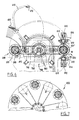
- the machine 100 includes a cutting and drying station 110 allowing to form from a sheet metal coil by cutting at least one strip of connected sectors between them by deformable links, and a winding station 200 comprising a mandrel 201.
- Station 110 includes a press 112 for cutting sectors in the sheet metal strip and a dryer 114 allowing the elimination of a lubricant used during the cutting of the sectors.
- the press 112 operates in the example considered at a rate higher than 100 strokes / minute, for example about 160 strokes / minute.
- the press 112 cuts a single sector 20 at a time, but it is not beyond the scope of the present invention using a press capable of cutting several sectors at the same time.
- the speed of the belt leaving station 110 is discontinuous, and the belt 12 jerks forward as it leaves station 110.
- Machine 100 has an area 300 configured to allow the web 12 to deform so as to compensate for a difference in speed between the speed of the strip at the exit of station 110 and that at the entrance of winding station 200.
- Zone 300 comprises a conveyor 310 comprising rollers 320 driven in rotation by a motor 330 by means of drive means 335.
- rollers 320 are slightly tapered, rotate around axes respective horizontal having an increasing inclination, with respect to a Y axis of reference, this axis Y being substantially perpendicular to the direction X of advancement of the strip 12 at the exit of station 110.
- the rollers 320 are arranged substantially transversely to the direction of advancement of the strip 12 and are driven, on the side of their largest diameter, in rotation by the motor 330, at an increasing speed when one moves away from the extension 110.
- the strip 12 is placed freely on the rollers 320 and passes approximately horizontally in the direction of the mandrel 201.
- the drive of the rollers at a speed higher than the average press output speed, and, in the example described, at increasing speeds, allows to maintain a tension in the strip 12 during its path in zone 300, by friction between the rollers 320 and the sectors 20.
- the conveyor 310 has a generally curvilinear shape, and comprises two walls 340 and 350, vertical in the example described, each comprising at least one curvilinear portion. These two walls 340 and 350 have a spacing which increases from the exit from station 110, which is maximum substantially halfway between station 110 and the extension 200, then decreases when you get closer to extension 200.
- the strip 12 runs in the conveyor 310 while approaching the wall 340. Conversely, when the speed of the strip 12 leaving the station 110 is more higher than that at the entrance to the winding station, the belt 12 runs in the conveyor 310 by approaching the wall 350.
- the connections 16 allow the strip 12 to be deform and move between walls 340 and 350.
- the zone 300 comprises, in the example illustrated, detectors 360 and 370 for detecting the position of the strip between the walls 340 and 350.
- 360 and 370 detectors are, for example, inductive sensors which detect the presence of the strip at their level, which is the case when it follows paths curvilinear 380 and 390 respectively.
- a device servo not shown changes the winding speed on the mandrel 201.
- the winding speed on the mandrel 201 is accelerated.
- the strip 12 reaches the detector 370 the winding around the mandrel is slowed down.
- the strip 12 which leaves the zone 300 is wound around the mandrel 201.
- the strip is pressed against the mandrel 201 by a notched roller 210 comprising notches 211 which come to cooperate with the link stacks 16 connecting the sectors 20 of the strip 12.
- the roller 210 is thus rotated during the winding of the strip.
- the roller 210 is fixed on a rotary arm 410 capable of moving away from the mandrel 201 under the action of a jack 420, in order to take the position shown in lines interrupted in FIG. 2.
- the roller 210 is moved away from the mandrel once the stack completed, to allow the extraction of the stack of the mandrel.
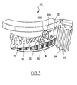
- the strip 12 of sectors 20 is pressed against the portion of strip already wound up by means of a set of rotating rollers 220, as illustrated in FIG. 3.
- the mandrel 201 is lowered as the strip is wound up by a motorized device located at its base or a jack device not shown in the figure 2, so that the upper layer of the stack is located throughout the duration of stacking at substantially the same height.
- the teeth 28 of the sectors 20 of the strip 12 are positioned on the mandrel 201 by means of latches 500, as illustrated in FIG. 4. These latches, which are at number of eight in the example illustrated, were not represented in figure 3 for the sake of clarity of the drawing.
- the latches 500 are capable of, each, sliding in a housing correspondent 230 of the mandrel 201.
- the latches 500 each have an end 510 which extends over substantially the entire length of the mandrel and which is capable of coming to cooperate with the ends of two teeth 28 located on either side of a notch 29 of a sector 20, to align these teeth with those of the layers already stacked, in a parallel direction to the axis of the winding.
- the latches 500 are each secured to a roller 520 capable of moving each in a cam path 530, produced in a central part 535 fixed relative to the peripheral part of the mandrel 201, rotary.
- Each cam path 530 has a shape allowing the latches to move between a projecting position, in which the end 510 cooperates with the teeth 28 in the notches 29, and an at least partially retracted position in the mandrel 201, which does not interfere with the approach of sectors 20 with the mandrel 201.
- Each latch 500 is in a projecting position when the rollers 520 corresponding are found in a portion 531 of the cam paths 530, as can be see it in figure 4.
- Each latch 500 is in a retracted position, not shown, when the corresponding rollers 520 are located in a portion 532 of the cam tracks 530, which is closer to the center of rotation of the mandrel 201 than the portion 531.
- the portions 531 and 532 are regularly alternated, and there are as many pairs of portions 531 and 532 as there are latches 500. All the latches 500 can be at the same time in the same position, either protruding or retracted, and the we pass from one position to another by making the mandrel rotate 1/2 n turns, where n denotes the number of latches.
- a magnetic circuit comprising on its outer circumference vertical stacks of connections 16, as illustrated in Figure 5.
- bars 18 having a cross section are welded U-shaped, comprising two wings 19 which are positioned in the example described from each side of a vertical row of connections 16.
- each bar 18 covers a single row of links 16, but it is not beyond the scope of the present invention when the bars 18 are wider and each cover several vertical rows of connections 16.
- the bars 18 can be fixed on the stack to a welding station which may be separate from the winding station.
- FIG. 6 shows a welding station 600 independent of the station winding.
- the mandrel 201 is supported by a rotary arm 710.
- a second mandrel 201 ′ is fixed to a rotary arm 730 diametrically opposite the arm 710.
- the two arms 710 and 730 are connected to a hub 700 which can be rotated about an axis vertical, and can be moved vertically by jacks or by a motorized device 750 during the winding of a strip of sectors on a mandrel 201 or 201 '.
- the hub 700 rotates 180 ° around its axis so as to bring the mandrel 201 to the location of the mandrel 201 'at the welding station 600.
- the bars 18 are then placed on the links 16, as illustrated in FIG. 5, and welded by means of two welding devices 610, each comprising two torches welding 612 placed at 90 ° to each other, and allowing each to be welded one of the wings 19 of a bar 18 on the stack.
- the mandrel placed at the welding station is able to be rotated by a device not shown, to allow the welding of several bars 18, successively.
- the mandrel 201 ′ is moved axially during the welding of the bars 18 by the cylinders or by the same motorized device 750 which maintains the level of removal at constant height. Welding on one of the mandrels 201 or 201 'can take place substantially at the same time as the winding of a strip of sectors on the other mandrel.
- the welding devices 610 are each supported by a retractable arm 614 rotatable, allowing them to be moved away from the mandrel 201 ′ in order to extract the stack when welding has been completed.
- the transfer of the mandrel from the winding station to the welding station can also be performed manually, without departing from the scope of the present invention.
Applications Claiming Priority (2)
| Application Number | Priority Date | Filing Date | Title |
|---|---|---|---|
| FR0201647A FR2835977B1 (fr) | 2002-02-11 | 2002-02-11 | Procede et machine pour la fabrication d'un circuit magnetique de machine electrique |
| FR0201647 | 2002-02-11 |
Publications (2)
| Publication Number | Publication Date |
|---|---|
| EP1335480A1 true EP1335480A1 (de) | 2003-08-13 |
| EP1335480B1 EP1335480B1 (de) | 2012-04-04 |
Family
ID=27589619
Family Applications (1)
| Application Number | Title | Priority Date | Filing Date |
|---|---|---|---|
| EP20030290315 Expired - Lifetime EP1335480B1 (de) | 2002-02-11 | 2003-02-07 | Verfahren und Vorrichtung zur Herstellung eines magnetischen Kreises einer elektrischen Maschine |
Country Status (7)
| Country | Link |
|---|---|
| US (1) | US7103964B2 (de) |
| EP (1) | EP1335480B1 (de) |
| CN (1) | CN100420127C (de) |
| AT (1) | ATE552644T1 (de) |
| BR (1) | BR0300306A (de) |
| FR (1) | FR2835977B1 (de) |
| MX (1) | MXPA03001243A (de) |
Cited By (2)
| Publication number | Priority date | Publication date | Assignee | Title |
|---|---|---|---|---|
| CN110465549A (zh) * | 2018-05-11 | 2019-11-19 | 株式会社电装 | 压轧弯曲机 |
| CN112769302A (zh) * | 2020-06-28 | 2021-05-07 | 温州职业技术学院 | 基于凸轮机械手的电机快速装配系统 |
Families Citing this family (9)
| Publication number | Priority date | Publication date | Assignee | Title |
|---|---|---|---|---|
| DE102004058659A1 (de) | 2004-12-06 | 2006-06-22 | Robert Bosch Gmbh | Fertigungseinrichtung und Verfahren zur Herstellung eines elektromagnetischen Elemensts für eine elektrische Maschine |
| US7829000B2 (en) * | 2005-02-25 | 2010-11-09 | Hewlett-Packard Development Company, L.P. | Core-shell solid freeform fabrication |
| FR2927736B1 (fr) * | 2008-02-20 | 2014-12-05 | Leroy Somer Moteurs | Stator de machine electrique tournante. |
| AT508600B1 (de) * | 2009-07-16 | 2011-05-15 | Andritz Tech & Asset Man Gmbh | Verfahren zum herstellen von rotor- und statorblechen |
| WO2012101812A1 (ja) * | 2011-01-28 | 2012-08-02 | 新日本製鐵株式会社 | 回転電機用螺旋コアの製造方法及び回転電機用螺旋コアの製造装置 |
| CN102364836B (zh) * | 2011-09-29 | 2014-03-26 | 福建农林大学 | 盘式电机定转子铁芯成形机 |
| GB2502385B (en) * | 2012-11-15 | 2014-07-09 | Emiliane Trancerie Spa | Method and apparatus for producing cores for electrical machines |
| JP6834899B2 (ja) * | 2017-10-18 | 2021-02-24 | トヨタ自動車株式会社 | 回転電機コアの製造方法 |
| CN109837728B (zh) * | 2019-01-24 | 2021-07-30 | 广州市艾维斯机电科技有限公司 | 一种自动切割出预定形状片的装置 |
Citations (6)
| Publication number | Priority date | Publication date | Assignee | Title |
|---|---|---|---|---|
| DE2053823A1 (de) * | 1970-11-02 | 1972-05-10 | L. Schuler GmbH, 7320 Göppingen | Transport- und Stapelvorrichtung für Bleche elektrischer Maschinen und Geräte |
| FR2171398A1 (de) * | 1972-02-10 | 1973-09-21 | Schuler Gmbh L | |
| US3854355A (en) * | 1972-10-05 | 1974-12-17 | Asea Ab | Method of punching sheet segments having substantially annular sector shape |
| US3890863A (en) * | 1973-09-05 | 1975-06-24 | Weingarten Ag Maschf | Stamping machine for slotting core plates |
| JPS59188356A (ja) * | 1983-04-08 | 1984-10-25 | Hitachi Ltd | 扇形状鉄板の姿勢揃え移送装置 |
| EP1120882A2 (de) * | 2000-01-28 | 2001-08-01 | Moteurs Leroy-Somer | Sektorenblechband und Verfahren zur Herstellung einer magnetischen Schaltung einer elektrischen Maschine |
Family Cites Families (22)
| Publication number | Priority date | Publication date | Assignee | Title |
|---|---|---|---|---|
| US3320451A (en) * | 1961-11-24 | 1967-05-16 | Gen Motors Corp | Dynamoelectric machine assembly |
| US3604464A (en) * | 1968-11-04 | 1971-09-14 | Callahan Mining Corp | Bendable metal duct |
| JPS4839610B1 (de) * | 1969-05-02 | 1973-11-26 | ||
| JPS5341321B1 (de) * | 1971-07-30 | 1978-11-02 | ||
| US4102040A (en) * | 1975-07-03 | 1978-07-25 | Societe Anonyme Pour L'equipement Electrique Des Vehicules S.E.V. Marchal | Method of manufacturing a curved component of a magnetic circuit |
| JPS55103061A (en) * | 1979-02-02 | 1980-08-06 | Hitachi Ltd | Blanking method of sector steel plate for rotary electric machine |
| DE3024407A1 (de) * | 1980-06-28 | 1982-01-21 | Michael Hörauf Maschinenfabrik, 7334 Süssen | Papierbecher aus oberflaechengeschuetztem karton |
| US4365180A (en) * | 1981-06-25 | 1982-12-21 | General Motors Corporation | Strip wound dynamoelectric machine core |
| DE3134080A1 (de) | 1981-08-28 | 1983-04-14 | Robert Bosch Gmbh, 7000 Stuttgart | Elektrische maschine, insbesondere drehstromgenerator, mit innenliegenden kuehlkanaelen |
| JPS60106349A (ja) * | 1983-11-15 | 1985-06-11 | Hitachi Ltd | 回転電機鉄心板の製造方法 |
| US4625957A (en) * | 1984-06-19 | 1986-12-02 | Paper Converting Machine Company | Apparatus for stacking and delivering paper napkins, paper towels, and the like |
| US4613780A (en) * | 1984-10-12 | 1986-09-23 | General Electric Company | Lanced strip and edgewise wound core |
| US4654552A (en) * | 1985-03-28 | 1987-03-31 | General Electric Company | Lanced strip and edgewise wound core |
| JP2888142B2 (ja) * | 1993-11-08 | 1999-05-10 | 三菱電機株式会社 | 回転電動機並びにその製造方法 |
| US5141219A (en) * | 1989-11-08 | 1992-08-25 | Idab Incorporated | Apparatus and method for separating a stream of lapped signatures into discrete batches |
| IT1238717B (it) * | 1990-04-27 | 1993-09-01 | Perini Navi Spa | Ribobinatrice con mezzi per variare il numero di perforazioni avvolte su ciascun rotolo in formazione |
| JP3430521B2 (ja) * | 1992-09-24 | 2003-07-28 | 松下電器産業株式会社 | 回転電機の固定子 |
| EP0823771B1 (de) * | 1996-02-23 | 2006-04-26 | Matsushita Electric Industrial Co., Ltd. | Motor |
| JP3568364B2 (ja) * | 1996-09-30 | 2004-09-22 | 松下電器産業株式会社 | 回転電機のコア |
| JP3359863B2 (ja) * | 1998-04-08 | 2002-12-24 | 三菱電機株式会社 | 固定子鉄芯の製造方法 |
| US6402004B1 (en) * | 1998-09-16 | 2002-06-11 | Hoya Corporation | Cutting method for plate glass mother material |
| DE19934858A1 (de) * | 1999-07-24 | 2001-01-25 | Abb Research Ltd | Rotierende elektrische Maschine und Verfahren zu deren Herstellung |
-
2002
- 2002-02-11 FR FR0201647A patent/FR2835977B1/fr not_active Expired - Fee Related
-
2003
- 2003-01-22 US US10/347,584 patent/US7103964B2/en not_active Expired - Fee Related
- 2003-02-07 AT AT03290315T patent/ATE552644T1/de active
- 2003-02-07 EP EP20030290315 patent/EP1335480B1/de not_active Expired - Lifetime
- 2003-02-08 CN CNB031025013A patent/CN100420127C/zh not_active Expired - Fee Related
- 2003-02-10 BR BR0300306A patent/BR0300306A/pt not_active IP Right Cessation
- 2003-02-10 MX MXPA03001243A patent/MXPA03001243A/es active IP Right Grant
Patent Citations (6)
| Publication number | Priority date | Publication date | Assignee | Title |
|---|---|---|---|---|
| DE2053823A1 (de) * | 1970-11-02 | 1972-05-10 | L. Schuler GmbH, 7320 Göppingen | Transport- und Stapelvorrichtung für Bleche elektrischer Maschinen und Geräte |
| FR2171398A1 (de) * | 1972-02-10 | 1973-09-21 | Schuler Gmbh L | |
| US3854355A (en) * | 1972-10-05 | 1974-12-17 | Asea Ab | Method of punching sheet segments having substantially annular sector shape |
| US3890863A (en) * | 1973-09-05 | 1975-06-24 | Weingarten Ag Maschf | Stamping machine for slotting core plates |
| JPS59188356A (ja) * | 1983-04-08 | 1984-10-25 | Hitachi Ltd | 扇形状鉄板の姿勢揃え移送装置 |
| EP1120882A2 (de) * | 2000-01-28 | 2001-08-01 | Moteurs Leroy-Somer | Sektorenblechband und Verfahren zur Herstellung einer magnetischen Schaltung einer elektrischen Maschine |
Non-Patent Citations (1)
| Title |
|---|
| PATENT ABSTRACTS OF JAPAN vol. 009, no. 047 (E - 299) 27 February 1985 (1985-02-27) * |
Cited By (2)
| Publication number | Priority date | Publication date | Assignee | Title |
|---|---|---|---|---|
| CN110465549A (zh) * | 2018-05-11 | 2019-11-19 | 株式会社电装 | 压轧弯曲机 |
| CN112769302A (zh) * | 2020-06-28 | 2021-05-07 | 温州职业技术学院 | 基于凸轮机械手的电机快速装配系统 |
Also Published As
| Publication number | Publication date |
|---|---|
| US7103964B2 (en) | 2006-09-12 |
| CN1438753A (zh) | 2003-08-27 |
| MXPA03001243A (es) | 2004-08-11 |
| US20040010907A1 (en) | 2004-01-22 |
| FR2835977A1 (fr) | 2003-08-15 |
| CN100420127C (zh) | 2008-09-17 |
| FR2835977B1 (fr) | 2004-07-02 |
| EP1335480B1 (de) | 2012-04-04 |
| ATE552644T1 (de) | 2012-04-15 |
| BR0300306A (pt) | 2004-08-10 |
Similar Documents
| Publication | Publication Date | Title |
|---|---|---|
| EP2205369B1 (de) | Vorrichtung zur prüfung eines blechstreifens | |
| EP1335480B1 (de) | Verfahren und Vorrichtung zur Herstellung eines magnetischen Kreises einer elektrischen Maschine | |
| LU83851A1 (fr) | Appareil d'alimentation de couches de renforcement au cours de la fabrication de pneumatiques | |
| EP0475886A1 (de) | Vorrichtung und Verfahren zum Öffnen einer Papierrolle und zum Verbinden von dem Ende einer Papierbahn an das Ende einer anderen Papierbahn | |
| FR2619557A1 (fr) | Dispositif de sortie pour textile en bande | |
| FR2744598A1 (fr) | Procede et appareil de production d'un aliment cylindrique, et aliment cylindrique | |
| EP0223632B1 (de) | Abwickelvorrichtung für Rollen | |
| FR2528023A1 (fr) | Procede et dispositif pour la reprise de produits plats se presentant en disposition en ecailles, en particulier pour la reprise de feuilles imprimees | |
| EP2013125B1 (de) | Verfahren und anlage zur inspektion eines gewickelten bands | |
| EP2112106B1 (de) | Verfahren und Vorrichtung zum Stoßschneiden und -verkleben für Rundschälmaschine | |
| CH390955A (fr) | Appareil pour empiler des feuilles | |
| EP3565777A1 (de) | Verfahren und vorrichtung zum kontinuierlichen kreuzwickeln von gummierstreifen um spulen | |
| FR2746681A1 (fr) | Procede et appareil d'alimentation en pieces longues | |
| EP0299885B1 (de) | Vorrichtung und Verfahren zum Stapeln von flachen Gegenständen | |
| WO2019008480A1 (fr) | Dispositif de support simultané de plusieurs rouleaux de matière imprimable | |
| FR2876365A1 (fr) | Procede et dispositif d'enroulement en bobine d'une bande | |
| EP3870430B1 (de) | Automatische vorrichtung und automatisches verfahren zum querwickeln von streifen von einer gewickelten bahn | |
| EP1946888A1 (de) | Lagerungs- und Verteilvorrichtung von Endlosförderbändern für eine robotisierte Anlage | |
| EP1588968B1 (de) | Trag- und Antriebsmodul eines aufgespulten bahnförmigen Materials für eine Bearbeitungsmaschine | |
| EP3583060B1 (de) | Verfahren und anlage zum kontinuierlichen querwickeln von gummistreifen zur formung von scheiben | |
| CH661910A5 (fr) | Procede et dispositif pour la separation et le transport de pieces de tissu. | |
| CA2511581C (fr) | Dispositif de pilotage d'entrainement de films dans un dispositif de realisation d'ensembles multicouches | |
| FR2692237A1 (fr) | Procédé et dispositif d'amenée de matériau en rouleau à un poste de préparation de colle. | |
| EP0144765A2 (de) | Verfahren und Vorrichtung für das Nageln von Dauben an einer Haspel | |
| EP0066892A1 (de) | Kontaktkopiervorrichtung für Schablonen |
Legal Events
| Date | Code | Title | Description |
|---|---|---|---|
| PUAI | Public reference made under article 153(3) epc to a published international application that has entered the european phase |
Free format text: ORIGINAL CODE: 0009012 |
|
| 17P | Request for examination filed |
Effective date: 20030213 |
|
| AK | Designated contracting states |
Designated state(s): AT BE BG CH CY CZ DE DK EE ES FI FR GB GR HU IE IT LI LU MC NL PT SE SI SK TR |
|
| AX | Request for extension of the european patent |
Extension state: AL LT LV MK RO |
|
| AKX | Designation fees paid |
Designated state(s): AT BE BG CH CY CZ DE DK EE ES FI FR GB GR HU IE IT LI LU MC NL PT SE SI SK TR |
|
| GRAP | Despatch of communication of intention to grant a patent |
Free format text: ORIGINAL CODE: EPIDOSNIGR1 |
|
| GRAS | Grant fee paid |
Free format text: ORIGINAL CODE: EPIDOSNIGR3 |
|
| GRAA | (expected) grant |
Free format text: ORIGINAL CODE: 0009210 |
|
| AK | Designated contracting states |
Kind code of ref document: B1 Designated state(s): AT BE BG CH CY CZ DE DK EE ES FI FR GB GR HU IE IT LI LU MC NL PT SE SI SK TR |
|
| REG | Reference to a national code |
Ref country code: GB Ref legal event code: FG4D Free format text: NOT ENGLISH |
|
| REG | Reference to a national code |
Ref country code: CH Ref legal event code: EP |
|
| REG | Reference to a national code |
Ref country code: AT Ref legal event code: REF Ref document number: 552644 Country of ref document: AT Kind code of ref document: T Effective date: 20120415 |
|
| REG | Reference to a national code |
Ref country code: IE Ref legal event code: FG4D Free format text: LANGUAGE OF EP DOCUMENT: FRENCH |
|
| REG | Reference to a national code |
Ref country code: DE Ref legal event code: R096 Ref document number: 60340468 Country of ref document: DE Effective date: 20120531 |
|
| REG | Reference to a national code |
Ref country code: NL Ref legal event code: VDEP Effective date: 20120404 |
|
| REG | Reference to a national code |
Ref country code: AT Ref legal event code: MK05 Ref document number: 552644 Country of ref document: AT Kind code of ref document: T Effective date: 20120404 |
|
| PG25 | Lapsed in a contracting state [announced via postgrant information from national office to epo] |
Ref country code: SI Free format text: LAPSE BECAUSE OF FAILURE TO SUBMIT A TRANSLATION OF THE DESCRIPTION OR TO PAY THE FEE WITHIN THE PRESCRIBED TIME-LIMIT Effective date: 20120404 Ref country code: SE Free format text: LAPSE BECAUSE OF FAILURE TO SUBMIT A TRANSLATION OF THE DESCRIPTION OR TO PAY THE FEE WITHIN THE PRESCRIBED TIME-LIMIT Effective date: 20120404 Ref country code: CY Free format text: LAPSE BECAUSE OF FAILURE TO SUBMIT A TRANSLATION OF THE DESCRIPTION OR TO PAY THE FEE WITHIN THE PRESCRIBED TIME-LIMIT Effective date: 20120404 Ref country code: FI Free format text: LAPSE BECAUSE OF FAILURE TO SUBMIT A TRANSLATION OF THE DESCRIPTION OR TO PAY THE FEE WITHIN THE PRESCRIBED TIME-LIMIT Effective date: 20120404 |
|
| PG25 | Lapsed in a contracting state [announced via postgrant information from national office to epo] |
Ref country code: PT Free format text: LAPSE BECAUSE OF FAILURE TO SUBMIT A TRANSLATION OF THE DESCRIPTION OR TO PAY THE FEE WITHIN THE PRESCRIBED TIME-LIMIT Effective date: 20120806 Ref country code: GR Free format text: LAPSE BECAUSE OF FAILURE TO SUBMIT A TRANSLATION OF THE DESCRIPTION OR TO PAY THE FEE WITHIN THE PRESCRIBED TIME-LIMIT Effective date: 20120705 |
|
| PG25 | Lapsed in a contracting state [announced via postgrant information from national office to epo] |
Ref country code: DK Free format text: LAPSE BECAUSE OF FAILURE TO SUBMIT A TRANSLATION OF THE DESCRIPTION OR TO PAY THE FEE WITHIN THE PRESCRIBED TIME-LIMIT Effective date: 20120404 Ref country code: CZ Free format text: LAPSE BECAUSE OF FAILURE TO SUBMIT A TRANSLATION OF THE DESCRIPTION OR TO PAY THE FEE WITHIN THE PRESCRIBED TIME-LIMIT Effective date: 20120404 Ref country code: AT Free format text: LAPSE BECAUSE OF FAILURE TO SUBMIT A TRANSLATION OF THE DESCRIPTION OR TO PAY THE FEE WITHIN THE PRESCRIBED TIME-LIMIT Effective date: 20120404 Ref country code: SK Free format text: LAPSE BECAUSE OF FAILURE TO SUBMIT A TRANSLATION OF THE DESCRIPTION OR TO PAY THE FEE WITHIN THE PRESCRIBED TIME-LIMIT Effective date: 20120404 Ref country code: NL Free format text: LAPSE BECAUSE OF FAILURE TO SUBMIT A TRANSLATION OF THE DESCRIPTION OR TO PAY THE FEE WITHIN THE PRESCRIBED TIME-LIMIT Effective date: 20120404 Ref country code: EE Free format text: LAPSE BECAUSE OF FAILURE TO SUBMIT A TRANSLATION OF THE DESCRIPTION OR TO PAY THE FEE WITHIN THE PRESCRIBED TIME-LIMIT Effective date: 20120404 |
|
| PLBE | No opposition filed within time limit |
Free format text: ORIGINAL CODE: 0009261 |
|
| STAA | Information on the status of an ep patent application or granted ep patent |
Free format text: STATUS: NO OPPOSITION FILED WITHIN TIME LIMIT |
|
| 26N | No opposition filed |
Effective date: 20130107 |
|
| PG25 | Lapsed in a contracting state [announced via postgrant information from national office to epo] |
Ref country code: ES Free format text: LAPSE BECAUSE OF FAILURE TO SUBMIT A TRANSLATION OF THE DESCRIPTION OR TO PAY THE FEE WITHIN THE PRESCRIBED TIME-LIMIT Effective date: 20120715 |
|
| REG | Reference to a national code |
Ref country code: DE Ref legal event code: R097 Ref document number: 60340468 Country of ref document: DE Effective date: 20130107 |
|
| PG25 | Lapsed in a contracting state [announced via postgrant information from national office to epo] |
Ref country code: BG Free format text: LAPSE BECAUSE OF FAILURE TO SUBMIT A TRANSLATION OF THE DESCRIPTION OR TO PAY THE FEE WITHIN THE PRESCRIBED TIME-LIMIT Effective date: 20120704 |
|
| BERE | Be: lapsed |
Owner name: MOTEURS LEROY-SOMER Effective date: 20130228 |
|
| PG25 | Lapsed in a contracting state [announced via postgrant information from national office to epo] |
Ref country code: MC Free format text: LAPSE BECAUSE OF NON-PAYMENT OF DUE FEES Effective date: 20130228 |
|
| REG | Reference to a national code |
Ref country code: CH Ref legal event code: PL |
|
| PG25 | Lapsed in a contracting state [announced via postgrant information from national office to epo] |
Ref country code: CH Free format text: LAPSE BECAUSE OF NON-PAYMENT OF DUE FEES Effective date: 20130228 Ref country code: LI Free format text: LAPSE BECAUSE OF NON-PAYMENT OF DUE FEES Effective date: 20130228 |
|
| REG | Reference to a national code |
Ref country code: IE Ref legal event code: MM4A |
|
| REG | Reference to a national code |
Ref country code: DE Ref legal event code: R119 Ref document number: 60340468 Country of ref document: DE Effective date: 20130903 |
|
| PG25 | Lapsed in a contracting state [announced via postgrant information from national office to epo] |
Ref country code: DE Free format text: LAPSE BECAUSE OF NON-PAYMENT OF DUE FEES Effective date: 20130903 Ref country code: BE Free format text: LAPSE BECAUSE OF NON-PAYMENT OF DUE FEES Effective date: 20130228 Ref country code: IE Free format text: LAPSE BECAUSE OF NON-PAYMENT OF DUE FEES Effective date: 20130207 |
|
| PGFP | Annual fee paid to national office [announced via postgrant information from national office to epo] |
Ref country code: IT Payment date: 20140226 Year of fee payment: 12 Ref country code: TR Payment date: 20140110 Year of fee payment: 12 Ref country code: FR Payment date: 20131230 Year of fee payment: 12 |
|
| PGFP | Annual fee paid to national office [announced via postgrant information from national office to epo] |
Ref country code: GB Payment date: 20140120 Year of fee payment: 12 |
|
| PG25 | Lapsed in a contracting state [announced via postgrant information from national office to epo] |
Ref country code: LU Free format text: LAPSE BECAUSE OF NON-PAYMENT OF DUE FEES Effective date: 20130207 Ref country code: HU Free format text: LAPSE BECAUSE OF FAILURE TO SUBMIT A TRANSLATION OF THE DESCRIPTION OR TO PAY THE FEE WITHIN THE PRESCRIBED TIME-LIMIT; INVALID AB INITIO Effective date: 20030207 |
|
| GBPC | Gb: european patent ceased through non-payment of renewal fee |
Effective date: 20150207 |
|
| REG | Reference to a national code |
Ref country code: FR Ref legal event code: ST Effective date: 20151030 |
|
| PG25 | Lapsed in a contracting state [announced via postgrant information from national office to epo] |
Ref country code: IT Free format text: LAPSE BECAUSE OF NON-PAYMENT OF DUE FEES Effective date: 20150207 |
|
| PG25 | Lapsed in a contracting state [announced via postgrant information from national office to epo] |
Ref country code: GB Free format text: LAPSE BECAUSE OF NON-PAYMENT OF DUE FEES Effective date: 20150207 |
|
| PG25 | Lapsed in a contracting state [announced via postgrant information from national office to epo] |
Ref country code: FR Free format text: LAPSE BECAUSE OF NON-PAYMENT OF DUE FEES Effective date: 20150302 |
|
| PG25 | Lapsed in a contracting state [announced via postgrant information from national office to epo] |
Ref country code: TR Free format text: LAPSE BECAUSE OF NON-PAYMENT OF DUE FEES Effective date: 20150207 |