EP0066892A1 - Kontaktkopiervorrichtung für Schablonen - Google Patents
Kontaktkopiervorrichtung für Schablonen Download PDFInfo
- Publication number
- EP0066892A1 EP0066892A1 EP82105059A EP82105059A EP0066892A1 EP 0066892 A1 EP0066892 A1 EP 0066892A1 EP 82105059 A EP82105059 A EP 82105059A EP 82105059 A EP82105059 A EP 82105059A EP 0066892 A1 EP0066892 A1 EP 0066892A1
- Authority
- EP
- European Patent Office
- Prior art keywords
- carriage
- installation according
- light
- sensitive material
- installation
- Prior art date
- Legal status (The legal status is an assumption and is not a legal conclusion. Google has not performed a legal analysis and makes no representation as to the accuracy of the status listed.)
- Withdrawn
Links
Images


Classifications
-
- G—PHYSICS
- G03—PHOTOGRAPHY; CINEMATOGRAPHY; ANALOGOUS TECHNIQUES USING WAVES OTHER THAN OPTICAL WAVES; ELECTROGRAPHY; HOLOGRAPHY
- G03B—APPARATUS OR ARRANGEMENTS FOR TAKING PHOTOGRAPHS OR FOR PROJECTING OR VIEWING THEM; APPARATUS OR ARRANGEMENTS EMPLOYING ANALOGOUS TECHNIQUES USING WAVES OTHER THAN OPTICAL WAVES; ACCESSORIES THEREFOR
- G03B27/00—Photographic printing apparatus
- G03B27/02—Exposure apparatus for contact printing
- G03B27/10—Copying apparatus with a relative movement between the original and the light source during exposure
-
- A—HUMAN NECESSITIES
- A41—WEARING APPAREL
- A41H—APPLIANCES OR METHODS FOR MAKING CLOTHES, e.g. FOR DRESS-MAKING OR FOR TAILORING, NOT OTHERWISE PROVIDED FOR
- A41H3/00—Patterns for cutting-out; Methods of drafting or marking-out such patterns, e.g. on the cloth
- A41H3/02—Making patterns by copying
Definitions
- the present invention relates to an installation for heliographing chablons, in particular chablons for the manufacture of ready-to-wear garments, arranged in a plane defined by a frame and having on one of its edges a location capable of receiving a lighting installation of preferably mobile, as well as a device capable of receiving a reserve of light-sensitive material and making it possible to unwind this material in order to place it on the face opposite to the lighting installation of the stencils arranged on said plane.
- the object of the present invention is to reduce the number of operations and thereby allow faster and safer work.
- this object is achieved by the fact that the device capable of receiving a reserve of light-sensitive material has the form of a coil support arranged on a carriage movable along a track of the heliographic table, the reel being able to receive a roll of light-sensitive material which can be transferred via a drive device to a winding device located on the mobile carriage along the heliographic table, a device for synchronization being provided for movement of the carriage and entrainment of the light-sensitive material, or vice versa.
- the device capable of receiving a reserve of light-sensitive material has the form of a coil support arranged on a carriage movable along a track of the heliographic table, the reel being able to receive a roll of light-sensitive material which can be transferred via a drive device to a winding device located on the mobile carriage along the heliographic table, a device for synchronization being provided for movement of the carriage and entrainment of the light-
- the carriage can be moved manually along the heliographic table.
- a column guide for the carriage along the edge of the table. , acting on the frame by a guide device. It is known that column guides make it possible to obtain elevated guide precision. (Instead of moving the carriage in a longitudinal movement, it is also possible to move it perpendicularly in several movements).
- Another simplification of handling can be achieved by the fact that another synchronization device is provided for the movement of the carriage carrying the light-sensitive material and of the mobile lighting installation, because thanks to this it is possible to carry out with a single movement the positioning of the gravure paper, its exposure and its removal.
- this synchronization device can be formed by a rigid mechanical connection, arranged between the carriage carrying the light-sensitive material and the lighting installation, so that according to an advantageous execution, the carriage carries even the lighting installation, which amounts to saying that the heliographic paper and the installation are arranged in a single box.
- the synchronization device can be constituted by traction means, for example in the form of a cable or a chain, arranged between the carriage carrying the light-sensitive material and the lighting installation.
- traction means for example in the form of a cable or a chain
- Synchronization devices of this kind are known for drive systems for paper machines, or for synchronization of cinematographic films and magnetic tapes. It is also possible to provide the two drive devices in the form of a step drive, for example of a stepping motor and to provide the synchronization device in the form of a cadence generator controlling the two drive devices. training.
- stepping drives of this kind can also be carried out using magnetic latching
- stepping motors are particularly suitable for this, since they can continuously run without further, without the rigid relationship between the pulses from the cadence generator and the steps will not get lost.
- the position indicators usually required in electronic synchronization devices, can be eliminated.
- a particularly simple and reliable construction for a carriage for a heliographic table according to the invention is achievable in that it is constituted as a mobile carriage along the heliographic table by means of wheels, at least one of which is connected to the device synchronization.
- the latter can be achieved by gears connecting the wheels of the mobile carriage along the heliographic table and the device for driving the light-sensitive material inside the carriage.
- the synchronization device may however also include a motion detector for advancing the paper and an electronic comparison and adjustment device.
- this kind of synchronization devices is well known in various fields of the art.
- the drive device for the winding installation can be analogous to that of advancing the material and can be identical to devices of this kind used in tape recorders.
- the circumferential speed increases with the size of the coil, even for a speed of constant training, but on the other hand variations in speed for small differences in the diameter of the coils are not large and can easily be compensated for (as is known in the construction of dictation devices with mini-cassettes). It is however recommended, particularly in the event of marked differences in the diameters of the coils, to provide a capstan and to equip the carriage with a pressure and / or drive device located on the opposite side of the light-sensitive material.
- This device can, for example, have the shape of a roller, pressing on the one hand the light-sensitive material against the plane of the templates, at least one of these rollers having to be designed as a driving roller. (One can also imagine constructions having transport and compression ribbons for the light-sensitive material along said plane). It is also possible to provide double capstan constructions, in which the front axis adjusts the drive speed while the other axis determines by its lower speed or even reverse, the tension of the light-sensitive material.
- the device for synchronizing the movement of the carriage along the heliographic table with the device for driving the material with a penetrating tooth or pin roller.
- the light-sensitive material in order to obtain perfect synchronization between the carriage on the one hand and the material and / or the trajectory of the carriage.
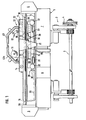
- a heliographic table 1 according to the invention rests on a frame 2 and can be pivoted about a longitudinal axis 3. To this end, the axis 3 can be driven by a motor not shown using a wheel 4 .
- Table 1 has, in addition to the gearboxes 5 to 8, a frame 9 (see fig, 2) defining a plane 10, on which the tailing stools are positioned. For this job, tilt the table 1 around 1 1 longitudinal axis 3, (see fig. 1) is particularly indicated and advantageous.
- the phenomenon of natural attraction between two materials can advantageously be implemented to achieve the aim of the present invention if a network of wires is associated with the surface of the support 51 of the heliographic table. of iron or steel wires 52, 53 and if the stirrups 54 are fitted with magnets 55, as is shown in FIG. 4.
- the support surface 51 which can be a glass reinforced with a network of wires 52, 53, a transparent synthetic sheet on the two faces of which are fixed wires 52, 53 or even a transparent sheet of glass or synthetic material carrying a network of magnetic or magnetizable lines printed or glued on one of its surfaces.
- the magnets 55 associated with the templates 54 can be synthetic plates containing, for example, barium ferrite particles or metallic magnets. They can be glued to the lower or upper surfaces of the stencils.
- the wires of the network are spaced from each other by 15 to 35 mm.
- magnets with a diameter of at least 20% greater than the distance between the wires on the stencils and by placing these magnets at distances between them of around 20 to 40 mm perfect positioning of the stencils can be achieved .
- one end of the network 66 is clamped in a groove 57 by means of a rod 58 using a clamping device (not shown) which presses the rod 58 towards the bottom of the groove 57.
- the other end of the network 66 can be fixed in a manner not shown on a tension roller which can be turned manually, for example using a lever (not shown), clockwise after having pinched the first end by means of the rod 8 in order to tension the network 66, this roller being retained by a stop pawl or a similar device not shown.
- each stencil has magnetized sheets or blades 55 glued to the lower surface by means of which it is fixed to the network of wires 66.
- the positioning of the stirrups 54 can be further facilitated if the table 65 is turned around its longitudinal axis 62 and is thus inclined or else placed in a vertical position. This is possible because of the attachment to a magnet according to the invention by which in the vertical position any movement of the templates 54 is avoided.
- the light-sensitive material is provided in the form of a paper strip, and is according to the invention on a reel 11 inside the carriage 12. It goes without saying that inside the carriage 12, a suspension device for the coil 11 must be provided.
- the carriage 12 could simply be moved by hand along the frame 9. In the embodiment shown in the drawing, it however has a number of wheels 13, 14. 14a and 15 (see fig. 2), of which in FIG. 1 only the wheels 14 are shown in order to facilitate its understanding.
- the carriage 12 is designed as a mobile carriage which can move along a track of the table 1, defined by column guides 16.
- the light-sensitive material is unwound in synchronism with the coil 11, deposited above the network and the stencils, exposed as described below and finally wound up. on the winding core 17.
- one of the wheels 13-15 can be designed as a movement detector of the carriage 12 by which a motor for driving the winding core 17 receives an adjustment signal. It should however be considered that during the unwinding of the light-sensitive material 17 from the coil 11, the latter always becomes smaller, while the coil on the core 17 always becomes larger. This can be considered in the adjustment by detection of the sizes of the coils for example. It is however simpler to obtain a regular advance of the material by the use of a capstan pin 19, driven in synchronism with the movement of the carriage.
- stepper motors for the capstan drive and the carriage drive and adjust them using a common cadence generator.
- the carriage 12 is however driven by a gear arranged in the housing 5 by means of a chain 20.
- the movement of the carriage is transmitted to the wheel 15 (fig. 2), having the form of '' a toothed wheel meshing with a rack disposed inside the guide column 16, as shown schematically from Figure 1, this movement is then transmitted to a needle coil 23 via a gear 22.
- the needle coil 23 (see figs. 1 and 2) fulfills a double function. On the one hand, it must guarantee a fixed meshing with the light-sensitive material 18 (provided that this does not have lateral perforation in the genre of films, in which case the needle coil would have to be replaced by a toothed roller. ).
- the axis 24 respectively 24a of the various needle crowns is inclined relative to the drive direction, as is known in the textile industry.
- a smoothing of the light-sensitive material is obtained in the lateral direction, in order to guarantee a winding without wrinkles.
- the inclination of the axes 24, 24a is shown in an exaggerated manner in FIG. 2 and is so weak in practice that a tearing of the material at the locations of the holes perforated by the needles does not occur on the short course on which the material 18 is in contact with the coil 23.
- a compression installation In order to arrange the light-sensitive material flat on the stencils placed in plane 10, a compression installation must be provided.
- This can be formed for example of leaf springs, folded at their edges and arranged longitudinally.
- it is however formed by 6 rollers 25.
- These rollers can, if necessary instead of the capstan pin 19, be driven at least in part.
- the roller 25 disposed closest to the winding core 17, regulates the speed of advance of the light-sensitive material, and that the other rollers 25 are not driven, driven to a lower speed, or even in the opposite direction, as is known from the double capstan drives in tape recorders, used to stretch the material 18 in the longitudinal direction.
- six rollers it is possible to provide several combinations.
- it is possible to provide for driving, in addition to the first roller, each second and for letting the intermediate rollers turn empty.
- the winding core 17 is driven by a sliding clutch, because - as already said - its diameter and thereby its circumferential speed increases.
- the advance should however only be defined by the movement of the carriage 12.
- the network in the plane 10 is pinched using fasteners 26.
- the latter are mounted on the frame 9 using separators 27, in a manner not shown.
- a lighting carriage 28 which is driven in synchronism with the carriage 12 by means of a chain gear, arranged inside the housing 5, and of a chain 29 in the housing 6.
- the chains 20, 29 for example, mesh with two chain wheels of the same dimension, then pass through the housings 8, 7 and 6 and return to the rear side of the carriage 12, respectively of the carriage lighting 28.
- the chain 29 (in fact a chain 29 is fixed on each side of the carriage) is fixed to the front side of the lighting carriage with a pin 30.
- the carriage 28 has an individual drive motor, one can make use of the possibilities of electronic adjustments and synchronization described above with regard to the synchronization of carriage movement and material advance, as co nnues in other fields of technology.
- the frame 9 can however also be equipped on its lower side (see fig. 2) with a notch or be open and be connected with the lighting carriage 28 by a rigid mechanical connection (see part 21).
- the frame 9 is open on its side so that the carriages 12 and 28 can be combined in a single construction unit.
- the frame 9 in the form of an open profile also serves as a guide for the lighting carriage 28.
- the table 1 is tiltable around its longitudinal axis 3, so that it is also necessary for. the carriage 12, to support it with its wheels 13 and 15 laterally, as is the case for the lighting carriage 28. For this reason, the latter carries, apart from the four wheels 32, also lateral wheels 33.
- the lighting carriage carries a number of lighting tubes 34, mounted in mounts 35 (fig. 2). The latter are fixed to a lamp holder in the form of a bowl, connected to a frame of the carriage 36.
- the energization is carried out by impedance coils 38, placed at the two ends of the carriage 28, which are connected to the electrical network. by brushes 29.
- the latter are moved laterally and cooperate by their elements 40, each with one of the electrical conductors 41, mounted on insulators 42, placed on the underside of the folded edge of the frame 9.
- the three electrical conductors 41 can, for example, correspond to the three phases of an alternating current network.
- a motor of the carriage 28 to the electrical network, if this carriage is equipped with a separate motor.
- a stepping motor it could be connected to the cadence generator common to the carriages 12 and 28.
- the pulses of a common cadence generator can be modified, if other motors are used. Since a synchronous movement of the carriages 12 and 28 is important, it is above all motors having good regular running properties, as do synchronous and asynchronous motors which lend themselves to such an application.
- the carriage 28 may have opposite rollers 25, counter-rollers, in order to guarantee correct operation of the sensitive material in the light 18 on the network, respectively on the stoppers arranged on the plane 10. This is especially indicated if at least one of the rollers 25 is driven for the advancement of the material.
- the gear used to actuate the winding core is not shown in the drawing, those skilled in the art readily recognize that it must build it like those used in tape recorders or other tape devices.
- the coil 11 is not normally driven, but can be in the case of high tension in the material. If, however, the tension of the light-sensitive material 18 in the longitudinal direction is too low, it may be advantageous to drive the coil 11 in the opposite direction by a soft slip clutch.
- the needle coil can be replaced by a roller having inclined elevations relative to its longitudinal axis.
Landscapes
- Engineering & Computer Science (AREA)
- Textile Engineering (AREA)
- Physics & Mathematics (AREA)
- General Physics & Mathematics (AREA)
- Replacement Of Web Rolls (AREA)
Applications Claiming Priority (4)
| Application Number | Priority Date | Filing Date | Title |
|---|---|---|---|
| CH378981 | 1981-06-10 | ||
| CH378881 | 1981-06-10 | ||
| CH3789/81 | 1981-06-10 | ||
| CH3788/81 | 1981-06-10 |
Publications (1)
| Publication Number | Publication Date |
|---|---|
| EP0066892A1 true EP0066892A1 (de) | 1982-12-15 |
Family
ID=25693843
Family Applications (1)
| Application Number | Title | Priority Date | Filing Date |
|---|---|---|---|
| EP82105059A Withdrawn EP0066892A1 (de) | 1981-06-10 | 1982-06-09 | Kontaktkopiervorrichtung für Schablonen |
Country Status (1)
| Country | Link |
|---|---|
| EP (1) | EP0066892A1 (de) |
Cited By (1)
| Publication number | Priority date | Publication date | Assignee | Title |
|---|---|---|---|---|
| GB2133567A (en) * | 1983-01-13 | 1984-07-25 | Giuseppe Paccagnella | Apparatus for a continuous contact exposure of photosensitive materials by means of a slot source of light |
Citations (10)
| Publication number | Priority date | Publication date | Assignee | Title |
|---|---|---|---|---|
| BE471346A (de) * | ||||
| US2427923A (en) * | 1942-03-28 | 1947-09-23 | Spaulding Moss Company | Apparatus for printing on lightsensitive material |
| DE904857C (de) * | 1951-12-20 | 1954-02-22 | Meteor Appbau Paul Schmeck G M | Verfahren und Vorrichtung zum Herstellen von Reflexkopien |
| US2919636A (en) * | 1954-01-05 | 1960-01-05 | Kron Oskar | Contact copying device |
| FR1327858A (fr) * | 1962-04-11 | 1963-05-24 | Machine de production et de reproduction de tracés de confection et analogues | |
| GB977365A (en) * | 1961-12-15 | 1964-12-09 | Eastman Kodak Co | Photographic printing apparatus |
| FR1409770A (fr) * | 1964-06-24 | 1965-09-03 | Kalle Ag | Procédé d'obtention d'un assemblage de corps solides présentant une forte adhérence, et ne faisant intervenir aucune matière |
| FR2019104A1 (de) * | 1968-09-28 | 1970-06-26 | Haus Hans | |
| DE2030639A1 (de) * | 1970-06-22 | 1971-12-30 | MD Papierveredelung GmbH, 8750 Aschaffenburg | Verfahren und Vorrichtung zum Fixieren einer Modellschablone auf einer Fläche |
| DE2649980A1 (de) * | 1976-10-30 | 1978-05-03 | Albrecht Bruno Dr Rer Pol | Selbsthaftende, gelochte schnittmusterfolie |
-
1982
- 1982-06-09 EP EP82105059A patent/EP0066892A1/de not_active Withdrawn
Patent Citations (10)
| Publication number | Priority date | Publication date | Assignee | Title |
|---|---|---|---|---|
| BE471346A (de) * | ||||
| US2427923A (en) * | 1942-03-28 | 1947-09-23 | Spaulding Moss Company | Apparatus for printing on lightsensitive material |
| DE904857C (de) * | 1951-12-20 | 1954-02-22 | Meteor Appbau Paul Schmeck G M | Verfahren und Vorrichtung zum Herstellen von Reflexkopien |
| US2919636A (en) * | 1954-01-05 | 1960-01-05 | Kron Oskar | Contact copying device |
| GB977365A (en) * | 1961-12-15 | 1964-12-09 | Eastman Kodak Co | Photographic printing apparatus |
| FR1327858A (fr) * | 1962-04-11 | 1963-05-24 | Machine de production et de reproduction de tracés de confection et analogues | |
| FR1409770A (fr) * | 1964-06-24 | 1965-09-03 | Kalle Ag | Procédé d'obtention d'un assemblage de corps solides présentant une forte adhérence, et ne faisant intervenir aucune matière |
| FR2019104A1 (de) * | 1968-09-28 | 1970-06-26 | Haus Hans | |
| DE2030639A1 (de) * | 1970-06-22 | 1971-12-30 | MD Papierveredelung GmbH, 8750 Aschaffenburg | Verfahren und Vorrichtung zum Fixieren einer Modellschablone auf einer Fläche |
| DE2649980A1 (de) * | 1976-10-30 | 1978-05-03 | Albrecht Bruno Dr Rer Pol | Selbsthaftende, gelochte schnittmusterfolie |
Non-Patent Citations (1)
| Title |
|---|
| MANUFACTURING CLOTHIER, vol.59, no.5, mai 1978, Londres (GB) * |
Cited By (1)
| Publication number | Priority date | Publication date | Assignee | Title |
|---|---|---|---|---|
| GB2133567A (en) * | 1983-01-13 | 1984-07-25 | Giuseppe Paccagnella | Apparatus for a continuous contact exposure of photosensitive materials by means of a slot source of light |
Similar Documents
| Publication | Publication Date | Title |
|---|---|---|
| FR2672878A1 (fr) | Dispositif de bobinage de matieres en bande ou en ruban. | |
| FR2676427A1 (fr) | Procede et dispositif de bobinage d'une bande de film. | |
| FR2584055A1 (fr) | Rupteuse pour papier en continu. | |
| EP0301989A1 (de) | Maschine zum Abwickeln von Bahnen mit Gestellen für Wickelrollen | |
| EP0223632B1 (de) | Abwickelvorrichtung für Rollen | |
| FR2528023A1 (fr) | Procede et dispositif pour la reprise de produits plats se presentant en disposition en ecailles, en particulier pour la reprise de feuilles imprimees | |
| EP0694897A1 (de) | Vorrichtung zur selektiven Anzeigung eines Bildes aus einem Satz solcher Bilder | |
| FR2726502A1 (fr) | Dispositif d'amenee d'une bande de papier a une plieuse d'une rotative d'impression a bobines | |
| EP0066892A1 (de) | Kontaktkopiervorrichtung für Schablonen | |
| EP0795504B1 (de) | Maschine zum kontinuierlichen Abwickeln von Rollen mit zumindest einer Einrichtung zum gleichzeitigen Abwickeln von zwei paarweise oder koaxial angeordneten Rollen | |
| EP0469130B1 (de) | Maschine zum bandschneiden, kleben und wickeln von anzeigen für werbetafeln mit rotierenden prismen | |
| EP1335480A1 (de) | Verfahren und Vorrichtung zur Herstellung eines magnetischen Kreises einer elektrischen Maschine | |
| EP0490789B1 (de) | Verfahren und Vorrichtung zur Herstellung von halbdurchlässigen Hohlfaserbündeln für Membranvorrichtungen | |
| FR2643487A1 (fr) | Appareil de depose et pose d'affiches predecoupees en bandes sur des panneaux publicitaires | |
| EP1147018B1 (de) | Verfahren und vorrichtung zur herstellung von personalisierten coupons | |
| EP1588968B1 (de) | Trag- und Antriebsmodul eines aufgespulten bahnförmigen Materials für eine Bearbeitungsmaschine | |
| EP0044814B1 (de) | Maschine zum Herstellen von Rollen aus einer Papierbahn | |
| FR2679888A1 (fr) | Procede et dispositif pour raccorder en continuite deux feuils minces. | |
| FR2655912A1 (fr) | Dispositif d'entrainement et de guidage d'une bande de papier ou similaire. | |
| BE1011594A3 (fr) | Procede de decoupage d'affiches et dispositif pour sa mise en oeuvre. | |
| FR2814731A1 (fr) | Dispositif de raccordement de precision pour une machine a derouler en continu | |
| FR2575111A1 (fr) | Appareil d'impression sans frappe | |
| CH621531A5 (en) | Device for continuously and automatically opening signatures intended to be assembled in order to form a book | |
| FR2503633A1 (fr) | Appareil d'avance de papier pour imprimante | |
| FR2497781A1 (fr) | Procede pour changer les bobines et les mandrins des machines d'enroulement sans axe |
Legal Events
| Date | Code | Title | Description |
|---|---|---|---|
| PUAI | Public reference made under article 153(3) epc to a published international application that has entered the european phase |
Free format text: ORIGINAL CODE: 0009012 |
|
| AK | Designated contracting states |
Designated state(s): DE FR GB IT NL |
|
| STAA | Information on the status of an ep patent application or granted ep patent |
Free format text: STATUS: THE APPLICATION IS DEEMED TO BE WITHDRAWN |
|
| 18D | Application deemed to be withdrawn |
Effective date: 19831121 |