EP1335168A2 - Anordnung zur Erhöhung der Temperaturwechselbeständigkeit von fluiddurchströmten, druckbelasteten Glasrohren - Google Patents
Anordnung zur Erhöhung der Temperaturwechselbeständigkeit von fluiddurchströmten, druckbelasteten Glasrohren Download PDFInfo
- Publication number
- EP1335168A2 EP1335168A2 EP03001412A EP03001412A EP1335168A2 EP 1335168 A2 EP1335168 A2 EP 1335168A2 EP 03001412 A EP03001412 A EP 03001412A EP 03001412 A EP03001412 A EP 03001412A EP 1335168 A2 EP1335168 A2 EP 1335168A2
- Authority
- EP
- European Patent Office
- Prior art keywords
- glass tube
- inner element
- arrangement
- tube
- glass
- Prior art date
- Legal status (The legal status is an assumption and is not a legal conclusion. Google has not performed a legal analysis and makes no representation as to the accuracy of the status listed.)
- Withdrawn
Links
Images



Classifications
-
- F—MECHANICAL ENGINEERING; LIGHTING; HEATING; WEAPONS; BLASTING
- F28—HEAT EXCHANGE IN GENERAL
- F28F—DETAILS OF HEAT-EXCHANGE AND HEAT-TRANSFER APPARATUS, OF GENERAL APPLICATION
- F28F1/00—Tubular elements; Assemblies of tubular elements
- F28F1/003—Multiple wall conduits, e.g. for leak detection
-
- F—MECHANICAL ENGINEERING; LIGHTING; HEATING; WEAPONS; BLASTING
- F24—HEATING; RANGES; VENTILATING
- F24S—SOLAR HEAT COLLECTORS; SOLAR HEAT SYSTEMS
- F24S10/00—Solar heat collectors using working fluids
- F24S10/40—Solar heat collectors using working fluids in absorbing elements surrounded by transparent enclosures, e.g. evacuated solar collectors
- F24S10/45—Solar heat collectors using working fluids in absorbing elements surrounded by transparent enclosures, e.g. evacuated solar collectors the enclosure being cylindrical
-
- F—MECHANICAL ENGINEERING; LIGHTING; HEATING; WEAPONS; BLASTING
- F28—HEAT EXCHANGE IN GENERAL
- F28F—DETAILS OF HEAT-EXCHANGE AND HEAT-TRANSFER APPARATUS, OF GENERAL APPLICATION
- F28F21/00—Constructions of heat-exchange apparatus characterised by the selection of particular materials
- F28F21/006—Constructions of heat-exchange apparatus characterised by the selection of particular materials of glass
-
- Y—GENERAL TAGGING OF NEW TECHNOLOGICAL DEVELOPMENTS; GENERAL TAGGING OF CROSS-SECTIONAL TECHNOLOGIES SPANNING OVER SEVERAL SECTIONS OF THE IPC; TECHNICAL SUBJECTS COVERED BY FORMER USPC CROSS-REFERENCE ART COLLECTIONS [XRACs] AND DIGESTS
- Y02—TECHNOLOGIES OR APPLICATIONS FOR MITIGATION OR ADAPTATION AGAINST CLIMATE CHANGE
- Y02E—REDUCTION OF GREENHOUSE GAS [GHG] EMISSIONS, RELATED TO ENERGY GENERATION, TRANSMISSION OR DISTRIBUTION
- Y02E10/00—Energy generation through renewable energy sources
- Y02E10/40—Solar thermal energy, e.g. solar towers
- Y02E10/44—Heat exchange systems
Definitions
- the invention relates to an arrangement for increasing the Resistance to temperature changes of fluid-flowed, pressure-loaded Glass tubes, in detail with the features from the preamble of Claims 1 and 13, further use of such an arrangement in one Heat exchanger or an absorber tube for solar panels.
- the invention was therefore based on the object of an arrangement for increasing the Resistance to temperature changes of fluid-flowed, pressure-loaded To develop glass tubes, which by a low constructive and manufacturing effort is characterized, low costs and with regard to the availability of the materials to be used, no special ones Makes demands. Processing should be as easy as possible and the individual Glass tube should be able to be integrated as easily as possible in this arrangement.
- the arrangement for increasing the resistance to temperature changes of fluid-flowed, pressure-loaded glass tubes comprises one of a fluid flowable and in this state pressure-resistant glass tube, in which
- a hollow cylindrical inner element is introduced, which has a smaller wall thickness than the glass tube and in the flowed state of the glass tube at least partially, preferably completely free of one is direct heat coupling with the glass tube. That is, the inner element fluid flows around on both sides - on the outer and inner circumference. The Flow around takes place when the inner element is completely coaxial Glass tube without pressure. Between the interior of the interior element and the rest There is a hydraulic coupling inside the glass tube, i.e.
- the inner element has a smaller wall thickness than that Glass tube on.
- Solution c is preferably used, since there are no particular ones Measures must be taken on the glass tube or inner element and thus uses standardized elements or prefabricated elements can be combined with an additional tour if necessary can.
- This guide can be positively and non-positively with the glass tube be connected.
- the guide is preferably fixed non-positively in the glass tube. for example by clamping.
- the guide can also with the inner element be coupled non-positively and / or positively.
- the connection between the guide and the inner element with a tension very large fit, so that only a rough fixation of the Inner element opposite the glass tube.
- the main function of leadership is in the position fixation in the de-energized state, especially during to see the transport of the arrangement according to the invention Avoid damage to the inner element or the glass tube.
- the inner element preferably extends over the entire axial Extension of the glass tube, so that over the entire length of the glass tube analog cooling behavior can be achieved.
- a large number of interior elements are provided, which are arranged adjacent to each other but free of one Are connected to each other. This has the advantage that the inner element is not must necessarily be adapted to the length of the glass tube, but prefabricated, possibly standardized inner part elements are also used here can be, which form the unit inner element by merging.
- the inner element is also from a tubular or tubular element formed, the inner circumference of the glass tube the Corresponds to the outer circumference of the inner element.
- material Plastics use, for example PTFE.
- the solution according to the invention can be used for glass tubes with only one Outer wall and glass tubes with tubes arranged inside for coaxial Guiding the flow medium.
- Special areas of application for the Arrangement according to the invention are heat exchangers in which the Heat transfer elements are formed by glass tubes and further Absorber tubes for solar collectors.
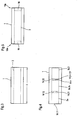
- FIG. 1 illustrates an arrangement according to the invention for increasing the temperature change resistance of fluid-flowed, pressure-loaded glass tubes using a schematically simplified sectional view through a glass tube 1.
- the arrangement is designated 2.
- This comprises an inner element 3 in the form of a thin-walled glass tube 19 which is inserted into the glass tube 1 to be protected, in particular the interior 10 enclosed by it.
- Glass tube 1 and inner element 3 are hydraulically coupled to one another, ie the inner element 3 does not form a separate interior from the interior 10.
- the outer diameter d A3 of the thin-walled tube 19 is smaller than the inner diameter d I1 of the glass tube 1.
- the thin-walled tube 19 has a smaller wall thickness s 3 than the glass tube 1.
- the wall thickness s 1 is a function of the pressure prevailing through the fluid in the glass tube 1. This requires a certain minimum wall thickness s 1 when flowing through.
- the minimum wall thickness of the thin-walled tube 19 can be significantly lower, since due to the flow on both sides, ie on the inner circumference and on the outer circumference, no one-sided pressure effect is exerted on the wall 6 of the inner element 3, which is designed as a thin-walled tube 19.
- a change in the temperature of the fluid flowing through the glass tube 1 causes a change in the temperature on the wall 7 of the glass tube 1 due to heat conduction, heat transfer and convection in the fluid, in particular that caused by the inner diameter d i . characterized inner surface 4.
- the glass tube 1 is filled with a cold fluid under standstill conditions.
- the temperature change can be approx. 250 K.
- the inner element 3 in the form of the thin-walled tube 19, there is also a transition between the latter and the wall 6 and the fluid due to convection in the fluid. There is therefore no direct heat exchange between the two tubes - glass tube 1 and tube 19 - but only an indirect heat exchange via the fluid flowing through the glass tube 1.
- the thin-walled tube 19 is preferably made of glass.
- FIGS. 2a and 2b illustrate an arrangement 2.2 according to the invention for a glass tube 1.2 with coaxial flow, such as can be used for example for vacuum tube collectors, in two sectional views.
- the glass tube 1.2 comprises a first outer tube 20 which is closed on one side and which forms the outer wall 9 for delimiting the interior 10.
- the glass tube 1.2 comprises a second inner glass tube 21, which is arranged in the interior 10 and enables coaxial flow through the glass tube 1.2.
- the second inner glass tube 21 is arranged coaxially with the first outer tube 20, which is closed on one side, and is designed to be open toward the inner circumference of the outer tube 20, in particular the closed side.
- the interior 10 is thus delimited by the inner circumference 8 of the inner glass tube 21, the outer circumference 11 of the second inner glass tube 21 and the inner circumference 12 of the outer wall 9, which is formed by the first outer tube 20, which is closed on one side.
- a hollow cylindrical inner element 3.2 in the form of a thin-walled tube 19.2, preferably made of glass, is introduced into the interior 10 of the hollow tube. This is arranged in the interior 10 between the inner tube 21 and the outer tube 20 such that it is partially, preferably completely free of contact with the outer periphery 11 and / or the inner periphery 12 of the inner glass tube 21 or that of the first outer one, at least in the flow-through state Tube 20 is formed outer wall 9.
- the wall thicknesses of the first outer tube 20 and the second inner tube 21 differ from the wall thickness s 3 , the tubes 20 and 21 being characterized by a greater wall thickness than that of the inner element 3.2.
- the inner tube 3.2 is therefore also referred to as a thin-walled tube.
- cooling on the inner circumference 12 of the outer wall 9 can be delayed due to the convection in the fluid and the heat transfer to the thin-walled tube 19.2, which contributes to improving the resistance to temperature changes of the glass tube 1.2.
- the second inner tube 21 withstands the thermal shock, since both the inner circumference 8 and the outer circumference 11 are flowed around. Inadmissible temperature gradients on the walls of the tubes 20 and 21 of the glass tube 1.2 can thus be avoided.
- the inner element is 3 designed as a thin-walled tube 19, 19.2, that is, as a tubular element with a fixed or constant cross-section.
- the thin-walled tube is also characterized by the fact that it extends axially through a solid shape is characterized.
- thin-walled instead of one Tube 19, 19.2 for the inner element 3, 3.2 also a tubular element, preferably a thin-walled elastic hose, preferably made of Plastic.
- the arrangement according to the invention then corresponds those described in Figures 1 and 2, but with the thin-walled Plastic hose a larger in both the radial and axial directions Flexibility than the thin-walled tube has.
- Possibility to free the interior elements 3, i.e. without fixing the situation opposite the glass tube 1 to lead in the glass tube 1. In this case, the position is fixed solely due to the fact that a fluid flows through the inner element 3 acting forces.
- this extends Inner element 3, as in Figure 3 for designs of the inner element as Inner tube or thin-walled plastic hose over the entire extension I the glass tube 1.
- the insertion of the Inner element 3 connected with increased effort should damage be avoided.
- To fulfill the function it is not absolutely necessary that the individual inner elements 3a to 3.n facing each other End faces 14.12 and 14.21 to 14.n2 and 14. (n + 1) 1, must touch.
- Figure 5 illustrates the design of the guides 15 and 16 in shape one holder each, which engages in the inner element 3 and opposite the inner circumference of the glass tube 1 is clamped.
- These guides 15 and 16 are preferably fixed non-positively in the glass tube 1, here by clamping.
- the guide can also be non-positively and / or positively with the inner element be coupled.
- unnecessary tensions are avoided the connection between guide 15 or 16 and inner element 3 with at least provided a game fit, so that only a rough fixation of the Inner element opposite the glass tube.
- the main function of leadership is in the position fixation in the de-energized state, especially during to see the transport of the arrangement according to the invention Avoid damage to the inner element or the glass tube.
- FIG. 6 illustrates a second embodiment of an arrangement 2.6 according to the invention for increasing the resistance to temperature changes of pressure-loaded glass tubes 1.6 through which fluid flows.
- the glass tube 1.6 is shown in cross-section in a schematically simplified representation.
- the outer diameter d A3 of the inner element 3.6 is dimensioned such that its outer surface 5.6 abuts the inner surface 4.6 of the glass tube 1.6.
- the inner element is not non-positively or positively connected to the glass tube 1.6.
- the wall 7.6 of the glass tube 1.6 and 6.6 of the inner element 3.6 functionally form a multi-layer wall 17.6, which consists of two layers.
- Both layers are characterized by a different heat transfer behavior, so that when the fluid flows through the tube with a low temperature, the inner surface 4.6 of the glass tube 1.6 is cooled only slowly, since wall 6.6 is interposed as the first layer. If a material is chosen for the wall 6.6, which has poor thermal conductivity, the cooling of the inner surface 4.6 can be delayed very much, so that impermissibly high stresses, which lead to damage to the glass tube 1.6, are avoided. Materials that have a high thermal resistance are preferably used for the inner element 3.6.
- the inner element 3.6 according to FIG. 6 can in turn be of a thin-walled glass tube are formed or a thin-walled tubular element, preferably a plastic tube.
- a plastic material is preferably used, which preferably also is characterized by a high thermal resistance.
- the Inner element 3.7 is in this case cohesive with the inner circumference 4.7 of the Glass tube 1.7 connected.
Landscapes
- Engineering & Computer Science (AREA)
- Physics & Mathematics (AREA)
- Thermal Sciences (AREA)
- Mechanical Engineering (AREA)
- General Engineering & Computer Science (AREA)
- Sustainable Development (AREA)
- Life Sciences & Earth Sciences (AREA)
- Sustainable Energy (AREA)
- Chemical & Material Sciences (AREA)
- Combustion & Propulsion (AREA)
- Heat-Exchange Devices With Radiators And Conduit Assemblies (AREA)
- Rigid Pipes And Flexible Pipes (AREA)
- Joining Of Glass To Other Materials (AREA)
Abstract
Description
- Figur 1
- verdeutlicht in schematisch vereinfachter Darstellung anhand eines Schnittes durch ein Glasrohr eine erste erfindungsgemäße Ausführung;
- Figuren 2a und 2b
- verdeutlichen anhand einer Schnittdarstellung durch ein Glasrohr eine zweite erfindungsgemäße Ausgestaltung;
- Figur 3
- verdeutlicht eine Ausführung mit Innenelement, welches sich in axialer Richtung über die Länge des Glasrohres erstreckt;
- Figur 4
- verdeutlicht eine Ausführung mit in axialer Richtung hintereinander angeordneten Innenelementen;
- Figur 5
- verdeutlicht eine Ausgestaltung mit Führung des Innenelementes im Glasrohr;
- Figur 6
- zeigt eine weitere Ausführung mit einem Innenelement, welches direkt wärmetechnisch mit der Wand des Glasrohres gekoppelt ist;
- Figur 7
- verdeutlicht eine Ausgestaltung eines Glasrohres mit Beschichtung an der Innenfläche.
- 1; 1.2; 1.6; 1.7
- Glasrohr
- 2; 2.2; 2.6; 2.7
- Anordnung zur Erhöhung der Temperaturwechselbeständigkeit fluiddurchströmter druckbelasteter Glasrohre
- 3; 3.2; 3.6; 3.7
- Innenelement
- 4
- Innenfläche des Glasrohres
- 5
- Außenfläche des Innenelementes
- 6
- Wand
- 7
- Wand
- 8
- Innenumfang
- 9
- Außenwand
- 10
- Innenraum
- 11
- Außenumfang
- 12
- Innenumfang
- 13a, 13b
- axiale Endbereiche
- 14.11 bis 14.nn
- Stirnseite
- 15
- Halterung
- 16
- Halterung
- 17
- Wand
- 18
- Beschichtung
- 19
- dünnwandiges Rohr
- 20
- erstes, einseitig verschlossenes äußeres Rohr
- 21
- zweites inneres Glasrohr
- dA3
- Außendurchmesser des Innenelementes
- dI1
- Innendurchmesser des Glasrohres
- dA1
- Außendurchmesser des Glasrohres
- dI3
- Innendurchmesser des Innenelementes
- s3
- Wandstärke des Innenelementes
- s1
- Wandstärke des Glasrohres
- s8
- Wandstärke der Innenwand 8
- s9
- Wandstärke der Außenwand 9
Claims (22)
- Anordnung (2; 2.2) zur Erhöhung der Temperaturwechselbeständigkeit von Glasrohren (1; 1.2)1.1 mit einem, von einem Fluid durchströmbaren Glasrohr (1; 1.2); gekennzeichnet durch die folgenden Merkmale:1.2 mit einem in das Glasrohr (1; 1.2) einschiebbaren hohlzylindrischen Innenelement (3; 3.2);1.3 der vom Innenelement (3; 3.2) umschlossene Hohlraum ist hydraulisch mit dem Innenraum des Glasrohres gekoppelt;1.4 die Wandstärke (s3) des Innenelementes (3; 3.2) ist kleiner als die Wandstärke des Glasrohres (1; 1.2);1.5 das Innenelement (3; 3.2) ist im fluiddurchströmten Zustand des Glasrohres wenigstens teilweise frei von einer direkten Wärmekopplung mit dem Glasrohr (1; 1.2);
- Anordnung (2; 2.2) nach Anspruch 1, dadurch gekennzeichnet, dass das Innenelement (3; 3.2) im fluiddurchströmten Zustand des Glasrohres (1, 1.2) vollständig frei von einer direkten Wärmekopplung mit dem Glasrohr (1; 1.2) ist.
- Anordnung (2; 2.2) nach Anspruch 1 oder 2, dadurch gekennzeichnet, dass das Innenelement (3; 3.2) von einem schlauchförmigen Element gebildet wird.
- Anordnung (2; 2.2) nach einem der Ansprüche 1 bis 3 dadurch gekennzeichnet, dass das Innenelement in axialer und/oder radialer Richtung flexibel ist.
- Anordnung (2; 2.2) nach einem der Ansprüche 1 bis 4, dadurch gekennzeichnet, dass das Innenelement (3; 3.2) aus Kunststoff besteht.
- Anordnung (2; 2.2) nach Anspruch 1 oder 2, dadurch gekennzeichnet, dass das hohlzylindrische Innenelement (3; 3.2) von einem dünnwandigen Glasrohr (19, 19.2) gebildet wird.
- Anordnung (2; 2.2) nach einem der Ansprüche 1 bis 6 dadurch gekennzeichnet, dass das Innenelement (3; 3.2) eine geringere Wärmeleitfähigkeit als das Glasrohr (1; 1.2) aufweist.
- Anordnung (2; 2.2) nach einem der Ansprüche 1 bis 7, dadurch gekennzeichnet, dass das Innenelement (3; 3.2) sich über die gesamte axiale Erstreckung des Glasrohres (1; 1.2) erstreckt.
- Anordnung (2; 2.2) nach einem der Ansprüche 1 bis 8, dadurch gekennzeichnet, dass eine Mehrzahl von Innenelementen (3a, 3b, 3c) vorgesehen ist, die einander benachbart angeordnet sind und frei von einer Verbindung miteinander.
- Anordnung (2; 2.2) nach einem der Ansprüche 1 bis 9, dadurch gekennzeichnet, dass das Innenelement (3) im Glasrohr (1; 1.2) geführt ist.
- Anordnung (2; 2.2) nach Anspruch 10, dadurch gekennzeichnet, dass die Führung im Glasrohr (1; 1.2) ausgebildet ist.
- Anordnung (2; 2.2) nach Anspruch 11, dadurch gekennzeichnet, dass das Innenelement mittels einer separaten Führung (15, 16) am Glasrohr (1; 1.2) geführt ist.
- Anordnung (2.2) nach einem der Ansprüche 1 bis 12 dadurch gekennzeichnet, dass das Glasrohr (1.2) ein erstes, einseitig geschlossenes äußeres Rohr (20) umfasst, welches die Außenwand (9) des Glasrohres (1.2) bildet, und ein zweites, in diesem angeordnetes inneres Glasrohr (21), welches zur verschlossenen Seite des äußeren Rohres (20) hin geöffnet ausgeführt ist, umfasst und das Innenelement (3.2) im fluiddurchströmten Zustand wenigstens teilweise frei von einer direkten Wärmekopplung mit dem äußeren und inneren Rohr (20, 21) ist.
- Anordnung (2.2) nach Anspruch 13, dadurch gekennzeichnet, dass das innere Rohr (21) koaxial zum äußeren Rohr (20) angeordnet ist.
- Anordnung (2; 2.2) nach einem der Ansprüche 1 bis 14, dadurch gekennzeichnet, dass der Außenumfang (11) des Innenelementes (3; 3.2) geringfügig kleiner ist, als der Innenumfang (12) des Glasrohres (1; 1.2).
- Anordnung (2.6; 2.7) zur Erhöhung der Temperaturwechsel-beständigkeit von Glasrohren (1; 1.2)16.1 mit einem von einem Fluid durchströmbaren Glasrohr (1; 1.2); gekennzeichnet durch die folgenden Merkmale:16.2 mit einem im Glasrohr (1.6; 1.7) angeordneten hohlzylindrischen Innenelement (3; 3.2), dessen Außenumfang (11) am Innenumfang (12) des Glasrohres (1.6, 1.7). anliegt.
- Anordnung (2.6) nach Anspruch 16, dadurch gekennzeichnet, dass das Innenelement (3.6) von einem schlauchförmigen Element gebildet wird.
- Anordnung (2.6) nach einem der Ansprüche 16 oder 17 dadurch gekennzeichnet, dass das Innenelement (3.6) in axialer und/oder radialer Richtung flexibel ist.
- Anordnung (2.6; 2.7) nach einem der Ansprüche 16 bis 18, dadurch gekennzeichnet, dass das Innenelement (3.6; 3.7) aus Kunststoff besteht.
- Anordnung (2.7) nach einem der Ansprüche 15 bis 18, dadurch gekennzeichnet, dass das Innenelement (3..7) stoffschlüssig mit dem Glasrohr (1.7) verbunden ist und eine Beschichtung (18) bildet.
- Verwendung einer Anordnung gemäß einem der Ansprüche 1 bis 20 in einem Wärmetauscher.
- Verwendung einer Anordnung gemäß einem der Ansprüche 1 bis 21 in einem Absorberrohr eines Sonnenkollektors.
Applications Claiming Priority (2)
| Application Number | Priority Date | Filing Date | Title |
|---|---|---|---|
| DE10205548A DE10205548B4 (de) | 2002-02-11 | 2002-02-11 | Anordnung zur Erhöhung der Temperaturwechselbeständigkeit von fluiddurchströmten, druckbelasteten Glasrohren |
| DE10205548 | 2002-02-11 |
Publications (2)
| Publication Number | Publication Date |
|---|---|
| EP1335168A2 true EP1335168A2 (de) | 2003-08-13 |
| EP1335168A3 EP1335168A3 (de) | 2006-05-24 |
Family
ID=27588525
Family Applications (1)
| Application Number | Title | Priority Date | Filing Date |
|---|---|---|---|
| EP03001412A Withdrawn EP1335168A3 (de) | 2002-02-11 | 2003-01-22 | Anordnung zur Erhöhung der Temperaturwechselbeständigkeit von fluiddurchströmten, druckbelasteten Glasrohren |
Country Status (4)
| Country | Link |
|---|---|
| US (1) | US7137413B2 (de) |
| EP (1) | EP1335168A3 (de) |
| JP (1) | JP4180934B2 (de) |
| DE (1) | DE10205548B4 (de) |
Cited By (3)
| Publication number | Priority date | Publication date | Assignee | Title |
|---|---|---|---|---|
| WO2008074852A2 (de) | 2006-12-19 | 2008-06-26 | Maik Schedletzky | Röhrenkollektor mit variabler wärmeleitfähigkeit der koaxialrohre |
| CN1661316B (zh) * | 2004-02-27 | 2010-06-23 | 淄博绿能环保设备科技有限公司 | 使用玻璃外壳热管作为换热元件的防腐换热装置 |
| CN1661315B (zh) * | 2004-02-27 | 2011-12-21 | 淄博环能海臣环保技术服务有限公司 | 玻璃外壳热管 |
Families Citing this family (10)
| Publication number | Priority date | Publication date | Assignee | Title |
|---|---|---|---|---|
| SE525007C2 (sv) * | 2003-03-17 | 2004-11-09 | Vattenfall Ab | Metod och anordning för att bromsa och desintegrera en i en ledningskanal framrusande vätskeplugg |
| WO2005088207A1 (de) * | 2004-03-15 | 2005-09-22 | Uestuen Orhan | Wärmetauscher mit vakuumröhre |
| US8613278B2 (en) * | 2008-03-28 | 2013-12-24 | Esolar, Inc. | Solar thermal receiver for medium- and high-temperature applications |
| US20170047887A1 (en) * | 2014-01-02 | 2017-02-16 | Donald Bennett Hilliard | Solar receiver and process |
| US10041747B2 (en) | 2010-09-22 | 2018-08-07 | Raytheon Company | Heat exchanger with a glass body |
| US10024578B1 (en) * | 2010-11-08 | 2018-07-17 | Randy L. Rutkai | Combination fence and solar heater for swimming pools |
| US20130048134A1 (en) * | 2011-08-25 | 2013-02-28 | The Boeing Company | Stagnant Fuel Thermal Insulation System |
| CN112429980A (zh) * | 2020-12-03 | 2021-03-02 | 信和光能(安徽)有限公司 | 一种高硼硅玻璃管 |
| CN113294920B (zh) * | 2021-06-09 | 2022-03-08 | 湖南科技大学 | 一种喷吸射流增强换热容积式太阳能吸热器 |
| CN113606633B (zh) * | 2021-06-29 | 2022-07-29 | 国网天津市电力公司电力科学研究院 | 双玻双面pv/t组件与热泵耦合的供暖系统及其控制方法 |
Family Cites Families (19)
| Publication number | Priority date | Publication date | Assignee | Title |
|---|---|---|---|---|
| US2460482A (en) * | 1945-02-20 | 1949-02-01 | Abbot Charles Greeley | Solar heat collector |
| DE943351C (de) * | 1953-09-06 | 1956-05-17 | Jenaer Glas Schott Gen Veb | Gefaesse und Rohre aus Glas, Quarz oder keramischen Stoffen fuer chemische Apparaturen |
| BE792348A (fr) * | 1971-12-28 | 1973-03-30 | Uss Eng & Consult | Procede de liaison de garnitures dans des tubes metalliques |
| US3952724A (en) * | 1974-06-24 | 1976-04-27 | Owens-Illinois, Inc. | Solar energy converter |
| US4186724A (en) * | 1976-11-22 | 1980-02-05 | American Solar | Solar energy collector |
| NL7703837A (nl) * | 1977-04-07 | 1978-10-10 | Philips Nv | Zonnecollector. |
| US4205655A (en) * | 1978-02-22 | 1980-06-03 | Corning Glass Works | Solar collector |
| US4194042A (en) | 1978-09-21 | 1980-03-18 | Corning Glass Works | Metallized glass-ceramic cooking vessels exhibiting extended service life |
| DE7834482U1 (de) * | 1978-11-20 | 1979-03-29 | Walde, Richard Stewart, Springfield Orchard, Ongar, Essex (Grossbritannien) | Rohr zur verwendung in solarheizeinrichtungen |
| US4554908A (en) * | 1979-08-29 | 1985-11-26 | Alpha-Omega Development Inc. | Electromagnetic energy absorber |
| US4299203A (en) * | 1979-11-13 | 1981-11-10 | Exxon Research & Engineering Co. | Tubular solar collector system |
| US4282857A (en) * | 1980-03-06 | 1981-08-11 | Owens-Illinois, Inc. | Solar energy collector assembly |
| JPS5856521Y2 (ja) * | 1981-07-06 | 1983-12-27 | 日東工器株式会社 | 真空二重管型太陽熱集熱管 |
| US4452233A (en) * | 1982-03-04 | 1984-06-05 | Goodman Jr Maurice | Solar energy collector |
| JPS5923057U (ja) * | 1982-08-04 | 1984-02-13 | 日東工器株式会社 | 太陽熱集熱器 |
| US4644934A (en) * | 1985-05-03 | 1987-02-24 | Kaus David P | Solar energy heating system |
| DE3821985C1 (de) * | 1988-06-30 | 1990-03-01 | Metalpraecis Berchem + Schaberg Gesellschaft Fuer Metallformgebung Mbh, 4650 Gelsenkirchen, De | |
| JPH0552428A (ja) * | 1991-08-21 | 1993-03-02 | Shiroki Corp | 太陽熱温水装置における真空二重集熱管 |
| DE29808532U1 (de) * | 1998-05-12 | 1998-10-01 | Schott-Rohrglas Gmbh, 95448 Bayreuth | Röhrenkollektor |
-
2002
- 2002-02-11 DE DE10205548A patent/DE10205548B4/de not_active Expired - Fee Related
-
2003
- 2003-01-22 EP EP03001412A patent/EP1335168A3/de not_active Withdrawn
- 2003-02-03 JP JP2003026314A patent/JP4180934B2/ja not_active Expired - Fee Related
- 2003-02-10 US US10/361,402 patent/US7137413B2/en not_active Expired - Fee Related
Cited By (4)
| Publication number | Priority date | Publication date | Assignee | Title |
|---|---|---|---|---|
| CN1661316B (zh) * | 2004-02-27 | 2010-06-23 | 淄博绿能环保设备科技有限公司 | 使用玻璃外壳热管作为换热元件的防腐换热装置 |
| CN1661315B (zh) * | 2004-02-27 | 2011-12-21 | 淄博环能海臣环保技术服务有限公司 | 玻璃外壳热管 |
| WO2008074852A2 (de) | 2006-12-19 | 2008-06-26 | Maik Schedletzky | Röhrenkollektor mit variabler wärmeleitfähigkeit der koaxialrohre |
| WO2008074852A3 (de) * | 2006-12-19 | 2009-10-08 | Maik Schedletzky | Röhrenkollektor mit variabler wärmeleitfähigkeit der koaxialrohre |
Also Published As
| Publication number | Publication date |
|---|---|
| EP1335168A3 (de) | 2006-05-24 |
| US7137413B2 (en) | 2006-11-21 |
| JP4180934B2 (ja) | 2008-11-12 |
| US20030221734A1 (en) | 2003-12-04 |
| DE10205548A1 (de) | 2003-08-21 |
| DE10205548B4 (de) | 2007-04-26 |
| JP2003240357A (ja) | 2003-08-27 |
Similar Documents
| Publication | Publication Date | Title |
|---|---|---|
| DE10205548B4 (de) | Anordnung zur Erhöhung der Temperaturwechselbeständigkeit von fluiddurchströmten, druckbelasteten Glasrohren | |
| DE102009028306B4 (de) | Doppelrohr | |
| EP2106515B1 (de) | Verbindungsanordnung für fluidleitungen | |
| EP2703707B1 (de) | System zum Herstellen einer dichten Rohrverbindung | |
| DE102013100886B4 (de) | Wärmetauscher für ein Kraftfahrzeug mit einem doppelwandigen Wärmetauscherrohr | |
| DE112009000126T5 (de) | Vorrichtung zum Koppeln von Komponenten eines Kraftstoffabgabesystems | |
| DE3403429A1 (de) | Kuehlereinheit fuer kunststoff-spritzgiessmaschine | |
| DE202009009910U1 (de) | Wärmetauscher mit Strömungsumlenker | |
| EP2926073B1 (de) | Wärmeübertrager | |
| EP2986882B1 (de) | Rohrverbindung zur durchleitung eines unter druck stehenden fluids | |
| DE102011113239A1 (de) | Wärmetauscher, insbesondere Abgaswärmetauscher für einen Kraftwagen | |
| DE602004000169T2 (de) | Doppelrohrverbindung und Herstellungsverfahrung | |
| EP2154409A1 (de) | Rohr für eine aus mehreren miteinander zu verbindenden bestehende Rohrleitung und Verfahren zur Verbindung von derartigen Rohren | |
| EP4235001A1 (de) | Thermisch isolierte transferleitung mit kuppelelement | |
| DE102010024276A1 (de) | Wärmeüberträger mit profiliertem Rohr in Rohr System | |
| DE102006024122B4 (de) | Vorrichtung zur Verbindung zweier Sammelrohre bei Kollektoren für Solaranlagen | |
| CH662634A5 (de) | Mediumfuehrende leitung mit mindestens einer drosselvorrichtung. | |
| DE102015001880A1 (de) | Verfahren und Vorrichtung zur Herstellung einer Kunststoffmatte mit Verstärkung am Kapillarrohr | |
| WO2011057594A1 (de) | Rohr-in-rohr-wärmetauscher | |
| DE4319006A1 (de) | Heiz/-Kühlkörperabdichtung | |
| EP2287552B1 (de) | Wärmeübertrager | |
| DE102007053002B4 (de) | Verbindungsanordnung für den Installationsbereich | |
| EP4141308A1 (de) | Rohrverbindungsanordnung | |
| DE102010001543A1 (de) | Wärmeübertrager | |
| DE3114297A1 (de) | Koaxial-waermeaustauscher |
Legal Events
| Date | Code | Title | Description |
|---|---|---|---|
| PUAI | Public reference made under article 153(3) epc to a published international application that has entered the european phase |
Free format text: ORIGINAL CODE: 0009012 |
|
| AK | Designated contracting states |
Designated state(s): AT BE BG CH CY CZ DE DK EE ES FI FR GB GR HU IE IT LI LU MC NL PT SE SI SK TR |
|
| AX | Request for extension of the european patent |
Extension state: AL LT LV MK RO |
|
| RAP1 | Party data changed (applicant data changed or rights of an application transferred) |
Owner name: SCHOTT AG |
|
| PUAL | Search report despatched |
Free format text: ORIGINAL CODE: 0009013 |
|
| AK | Designated contracting states |
Kind code of ref document: A3 Designated state(s): AT BE BG CH CY CZ DE DK EE ES FI FR GB GR HU IE IT LI LU MC NL PT SE SI SK TR |
|
| AX | Request for extension of the european patent |
Extension state: AL LT LV MK RO |
|
| 17P | Request for examination filed |
Effective date: 20060701 |
|
| 17Q | First examination report despatched |
Effective date: 20061204 |
|
| AKX | Designation fees paid |
Designated state(s): DE ES FR GB IT |
|
| STAA | Information on the status of an ep patent application or granted ep patent |
Free format text: STATUS: THE APPLICATION HAS BEEN WITHDRAWN |
|
| 18W | Application withdrawn |
Effective date: 20090131 |