EP1333205B1 - Drehschieber - Google Patents
Drehschieber Download PDFInfo
- Publication number
- EP1333205B1 EP1333205B1 EP20020027451 EP02027451A EP1333205B1 EP 1333205 B1 EP1333205 B1 EP 1333205B1 EP 20020027451 EP20020027451 EP 20020027451 EP 02027451 A EP02027451 A EP 02027451A EP 1333205 B1 EP1333205 B1 EP 1333205B1
- Authority
- EP
- European Patent Office
- Prior art keywords
- housing
- rotary slide
- region
- slide according
- reception
- Prior art date
- Legal status (The legal status is an assumption and is not a legal conclusion. Google has not performed a legal analysis and makes no representation as to the accuracy of the status listed.)
- Expired - Lifetime
Links
- 239000000463 material Substances 0.000 claims description 24
- 239000004033 plastic Substances 0.000 claims description 12
- 229920003023 plastic Polymers 0.000 claims description 12
- 238000005260 corrosion Methods 0.000 claims description 9
- 230000007797 corrosion Effects 0.000 claims description 9
- 238000007789 sealing Methods 0.000 claims description 5
- 238000001746 injection moulding Methods 0.000 claims description 4
- 239000002184 metal Substances 0.000 claims description 4
- 238000003466 welding Methods 0.000 claims description 4
- 239000002990 reinforced plastic Substances 0.000 claims description 3
- 238000013022 venting Methods 0.000 claims 2
- 239000007789 gas Substances 0.000 description 4
- 238000013461 design Methods 0.000 description 3
- 238000009826 distribution Methods 0.000 description 3
- 238000010276 construction Methods 0.000 description 2
- 238000004519 manufacturing process Methods 0.000 description 2
- -1 polyethylene Polymers 0.000 description 2
- 230000003014 reinforcing effect Effects 0.000 description 2
- 238000013519 translation Methods 0.000 description 2
- XLYOFNOQVPJJNP-UHFFFAOYSA-N water Substances O XLYOFNOQVPJJNP-UHFFFAOYSA-N 0.000 description 2
- 229920000049 Carbon (fiber) Polymers 0.000 description 1
- 229920002430 Fibre-reinforced plastic Polymers 0.000 description 1
- 239000004698 Polyethylene Substances 0.000 description 1
- 239000004743 Polypropylene Substances 0.000 description 1
- 238000004026 adhesive bonding Methods 0.000 description 1
- 239000004917 carbon fiber Substances 0.000 description 1
- 238000003889 chemical engineering Methods 0.000 description 1
- 238000004891 communication Methods 0.000 description 1
- 150000001875 compounds Chemical class 0.000 description 1
- 238000013016 damping Methods 0.000 description 1
- 230000001419 dependent effect Effects 0.000 description 1
- 238000011161 development Methods 0.000 description 1
- 230000018109 developmental process Effects 0.000 description 1
- 239000013536 elastomeric material Substances 0.000 description 1
- 239000011151 fibre-reinforced plastic Substances 0.000 description 1
- 239000003365 glass fiber Substances 0.000 description 1
- 238000002347 injection Methods 0.000 description 1
- 239000007924 injection Substances 0.000 description 1
- 238000009434 installation Methods 0.000 description 1
- 238000000034 method Methods 0.000 description 1
- 229920000573 polyethylene Polymers 0.000 description 1
- 229920001155 polypropylene Polymers 0.000 description 1
- 239000012744 reinforcing agent Substances 0.000 description 1
- 239000010865 sewage Substances 0.000 description 1
- 238000009423 ventilation Methods 0.000 description 1
- 239000002351 wastewater Substances 0.000 description 1
Images



Classifications
-
- F—MECHANICAL ENGINEERING; LIGHTING; HEATING; WEAPONS; BLASTING
- F16—ENGINEERING ELEMENTS AND UNITS; GENERAL MEASURES FOR PRODUCING AND MAINTAINING EFFECTIVE FUNCTIONING OF MACHINES OR INSTALLATIONS; THERMAL INSULATION IN GENERAL
- F16K—VALVES; TAPS; COCKS; ACTUATING-FLOATS; DEVICES FOR VENTING OR AERATING
- F16K3/00—Gate valves or sliding valves, i.e. cut-off apparatus with closing members having a sliding movement along the seat for opening and closing
- F16K3/02—Gate valves or sliding valves, i.e. cut-off apparatus with closing members having a sliding movement along the seat for opening and closing with flat sealing faces; Packings therefor
- F16K3/04—Gate valves or sliding valves, i.e. cut-off apparatus with closing members having a sliding movement along the seat for opening and closing with flat sealing faces; Packings therefor with pivoted closure members
- F16K3/06—Gate valves or sliding valves, i.e. cut-off apparatus with closing members having a sliding movement along the seat for opening and closing with flat sealing faces; Packings therefor with pivoted closure members in the form of closure plates arranged between supply and discharge passages
-
- Y—GENERAL TAGGING OF NEW TECHNOLOGICAL DEVELOPMENTS; GENERAL TAGGING OF CROSS-SECTIONAL TECHNOLOGIES SPANNING OVER SEVERAL SECTIONS OF THE IPC; TECHNICAL SUBJECTS COVERED BY FORMER USPC CROSS-REFERENCE ART COLLECTIONS [XRACs] AND DIGESTS
- Y10—TECHNICAL SUBJECTS COVERED BY FORMER USPC
- Y10T—TECHNICAL SUBJECTS COVERED BY FORMER US CLASSIFICATION
- Y10T137/00—Fluid handling
- Y10T137/8158—With indicator, register, recorder, alarm or inspection means
- Y10T137/8225—Position or extent of motion indicator
Definitions
- the invention relates to a rotary valve for a medium-carrying pipeline comprising a housing with two connection areas between two pipe ends housing with a locking member for shutting off the pipeline and with an actuator for actuating the locking member, wherein the housing has a first receiving area for receiving the locking member in the closed Position of the rotary valve, a second receiving portion for receiving the locking member in the open position of the rotary valve and a drive portion for receiving the actuating device, wherein the drive portion is arranged in the housing separate from the first and second receiving portion.
- valves or dampers are used as shut-off devices in main and distribution lines.
- the obturator is installed in the medium-carrying pipeline and consists essentially of a first region for connection to the pipeline, a second region for receiving the locking member in the open state of the obturator and a third region for receiving the actuating device, which is usually formed as a spindle drive.
- the slides often have on both sides of the valve body flanges, with which the obturator can be installed in the pipeline.
- the pipelines can be designed as a distribution network of a supply system.
- the medium in the pipeline can be gas, water or wastewater.
- valves or valves are used, which have a perpendicular to the pipe axis disk-shaped shut-off, which is moved in a direction perpendicular to the pipe axis extending plane from the pipe.
- the movement type of the shut-off disc may be a straight-line or a rotary or pivoting movement in this plane.
- the axis of rotation is running while perpendicular to the pipe axis and can be inside or outside the shut-off.
- the most important advantage of this design is the relatively short length, ie the space required in the axial direction of the pipeline is minimal.
- the overall height is relatively large, that is, when laid in the ground lines with a shut-off device with a large height, the line itself be buried relatively deep.
- a generic rotary valve is known.
- a so-called pendulum slider for applications under high vacuum in high-purity gas damping systems is described.
- the rotary valve is used in a vacuum system together with a turbo vacuum pump as a control element to adjust the vacuum in the system as accurately as possible.
- the housing and the slide are constructed of several individual parts of metal and designed for a relatively low pressure resistance.
- the slider is then pressed against the pivoting movement from the open position in the closed position to a seat in the housing.
- the lever arm which connects the shut-off disc with the actuator, acts together with a ramp in the region of the pivot axis of the actuator. With this ramp is achieved that the disc is moved towards the seat in the axial direction at the end of the pivoting movement.
- a shut-off device for gas supply lines is also known.
- the shut-off member is a flat valve disc, which is arranged between two flanges formed plastic housing parts.
- the first housing part and the second housing part are connected to a supply line extending from bottom to top and perpendicular to the valve disc.
- the second housing part additionally has an open transverse bore for a horizontally extending line.
- the drive shaft for the movement of the valve disc runs parallel to the axis of the supply line.
- the movement of the drive axle is facilitated by a coaxially arranged reduction gear.
- a gate valve for delivery lines of bulk materials is also known.
- the housing is parallel to the line axis divided in a first receiving area for receiving the slider in the closed position and in a second receiving area for receiving the slider in the open position.
- the actuating device is arranged outside the housing and comprises a pivot lever and a cylinder as a pivot drive.
- a rotary valve which can be made as compact and corrosion-resistant as possible from as few and easy to manufacture items.
- the rotary valve should also be as easy to install in existing piping systems.
- a rotary valve for a medium-carrying pipeline comprising a housing with two connection areas between two pipe ends housing with a locking member for shutting off the pipeline and with an actuator for actuating the locking member, wherein the housing has a first receiving area for receiving the locking member in the closed Position of the rotary valve, a second receiving portion for receiving the locking member in the open position of the rotary valve and a drive portion for receiving the actuating device, wherein the drive portion is arranged in the housing separate from the first and second receiving portion, wherein the actuating device is a lever arm, a nut and a spindle, wherein the spindle is arranged perpendicular to the axis of the connection areas.
- the spatially separated arrangement of the drive range contributes greatly to increasing the corrosion resistance and the life of the rotary valve.
- the rotary valve is constructed as compact as possible. This is achieved in that both the receiving areas and the drive area in the direction of the pipeline axis form three substantially equal areas of the housing. This is also achieved by arranging the receiving regions and the driving region in the direction of the pipeline axis substantially in the manner of an equilateral triangle adjacent to one another in the housing.
- the compact design of the rotary valve means that pipelines that are laid in the ground no longer need to be buried unnecessarily deep.
- the rotary valve can be easily made. This is achieved in that the drive region, the first receiving region and at least the largest part of the second receiving region are formed as a one-piece housing. This is also achieved by virtue of the fact that the housing is essentially mirror-symmetrical with respect to a mirror surface extending through the housing perpendicular to the pipe axis.
- the actuating device is arranged in the drive region sealed against the medium in the first and the second receiving area.
- the housing with the Receiving areas and the drive area are each formed of a corrosion-resistant material.
- the housing with the receiving areas and the drive area are each formed from a single cast in a plastic injection molding process.
- all areas of the obturator, which can be touched by the medium are formed of a corrosion-resistant material.
- all areas of the obturator, which can be touched by the medium are formed of a pure or a reinforced plastic material.
- the rotary valve can be easily installed in an existing pipeline.
- the housing in the first receiving area on two opposite sides each have a connection area for connection to the medium-carrying pipeline, wherein at least the material of the connection area is compatible with the material of the pipeline.
- the connection area is designed as an electric welding sleeve.
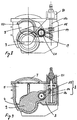
- a housing 1 of an inventive rotary valve is seen from above on the housing 1, that is, in a direction which is perpendicular to the pipe axis X, shown.
- the housing 1 is mirror-symmetrical or substantially mirror-symmetrical with respect to a mirror surface Y, which is perpendicular to the pipe axis X.
- a cover plate 7 is arranged, which closes the housing from above. Laterally next to the pipe axis X, a drive region 3 can be seen.
- FIGS. 1 and 2 show the drive region 3, a first receiving region 4 and a second receiving region 5. Adjacent to the second receiving area 5, the end cover 7 can be seen.
- the drive region 3 serves to receive an actuating device 8, which can be better seen in FIGS. 6 to 9.
- the actuating device serves to actuate a locking member 9.
- the locking member 9 can be moved by means of the actuating device 8 in the drive region 3 from the first receiving area 4 into the second receiving area 5.
- the end cover 7 can be detachably connected to the housing 1 by gluing or welding or by screwing.
- the end cover 7 can increase the stability of the housing 1. If the locking member 9 must be replaced and if the inner walls of the housing 1 must be cleaned, the end cover 7 can also be designed so that it can be removed.
- the housing 1 may optionally be constructed of two nearly mirror-symmetrical halves.
- FIG. 3 shows how the drive region 3, the first receiving region 4 and the second receiving region 5, for example, all occupy an approximately equal part of the housing 1. Viewed in the direction of the pipe axis X, the three regions 3, 4, 5 can, for example, occupy approximately equal cross-sectional areas.
- the receiving areas 4, 5 and the drive area 3 are arranged relative to one another, such as on the vertices of an equilateral or at least one isosceles triangle.
- the housing 1 thus has in a plane which is perpendicular to the pipe axis X, the smallest possible surface area.
- the housing 1 is similar to that shown in Figures 1 and 3, but without end cap 7. Also, the obturator 9 has been omitted to release the view of the interior of the housing 1. Inside the housing 1 guide ribs 10 and sealing surfaces 11 can be seen, which serve for a guide and sealing of the shut-9. Also, the actuator 8 has been omitted. In the drive area 3, a bearing 13 is visible. The bearing 13 is arranged at the interface between the two receiving regions 4, 5 and the drive region 3. The bearing 13 may also be formed mirror-symmetrically on the front and the back of the housing 1.
- the housing 1 may be made, for example, from a single mold in an injection molding process of a pure or reinforced plastic material or of another corrosion-resistant material.
- plastic material for buried pipelines for example, polyethylene or polypropylene can be used.
- reinforcing agents glass or carbon fibers or other non-polymeric materials may be used. All areas that can be contacted by the medium in the pipeline are made of a suitable plastic material. This ensures a high resistance to corrosion.
- FIG. 7 shows the housing 1 cut in a plane perpendicular to the pipe axis X. This plane can also be the plane Y be the symmetry for the housing 1. From Figures 6 and 7, the compact arrangement of the two receiving areas 4, 5 and the drive area 3 is well out.
- 5 and 6 and ribs 12 can be seen on the outside of the housing 1.
- the ribs 12 may be formed as longitudinal and / or as transverse ribs.
- the ribs 12 serve inter alia as reinforcing ribs for the walls of the housing 1.
- the arrangement of the reinforcing ribs 12, the walls of the housing 1 can be made much thinner, which significantly contributes to the material and weight saving of the housing 1.
- the bearing 13 is located where the three areas meet 3,4,5 together.
- the locking member 9 is essentially a disc of plastic material.
- the disc 9 is fixedly connected in the region of the bearing 13 with a lever arm 14, which in turn is movably connected to a nut 15 which is moved by a spindle 16 up and down.
- the spindle 16, the nut 15 and the lever arm 14 are preferably all made of metal. However, the spindle, the nut and the lever arm can also be honored from a plastic or, for example, from a fiber-reinforced plastic material, if the forces occur.
- the lever arm 14 may be carried out both on one side and on both sides. In the double-sided version, two identical lever arms 14 are located on both sides of the housing 1.
- the drive region 3 is not touched by the medium.
- the spindle 16 can be connected to a drive motor, not shown, for driving the spindle.
- a translation between the movement of the disc 9 and the spindle 16 is achieved.
- This combination has the consequence that the spindle 16 has a shorter length than in commercial rotary valves. This contributes to a smaller housing 1 and a compact construction as possible of the rotary valve.
- the spindle 16 is also less loaded by the translation and therefore can be performed accordingly easier and easier.
- a shaft 17, which is made for example of metal.
- the sealing of the driving area 3 is achieved by means of seals 20 acting on the shaft 17, between the shaft 17 and the front and the rear side of the housing 1 are arranged in the region of the bearing 13.
- the spindle 16 is mounted in the drive region 3 and held by two plates 19, which also serve as upper and lower stop for the nut 15.
- FIGS. 8 and 9 the obturator is again depicted as similar to FIGS. 6 and 7.
- Figure 8 it can be seen how the disc 9 can be pivoted away from the first receiving portion 4 in the second receiving portion 5, when the combination of nut 15 and spindle 16 is actuated.
- the disk 9 and the lever arm 14 are drawn in two different positions. An upper position, in which the disc 9 has been completely pivoted away from the first receiving portion 4 in the second receiving portion 5 and in which the pipe is completely released for the passage of the medium, and a second position in which the disc 9 is still partially in first receiving area 4 is located.
- FIG. 8 also shows a seal 20 for sealing the shaft 17 and the drive region 3 against the medium.
- a device 21 for limiting the torque of the actuating device 8 is arranged on top of the spindle 16.
- the torque limiting device 21 is designed here as a slip clutch, but may also be formed, for example, as a shear pin. With the slip clutch 21 prevents the spindle 16 is operated with a large torque. Especially in the two end positions of the disc 9, that is both in the fully open position and in the fully closed position of the obturator is thus prevented that too great a force is exerted on the disc 9. This ensures that the obturator is insensitive to mishandling during opening and closing.
- the slip clutch 21 may be configured to deliver an audible sound or other signal when the torque is exceeded.
- FIGS. 6, 7 and 8 also show how a seal 22 is arranged between the disk 9 and the housing 1.
- the seal 22 is a part, for example of an elastomeric material, which rests in the lower region of the disc 9 at its periphery and is arranged in the upper region of the disc 9 on both sides in the edge region of the disc 9.
- the seal 22 is preferably placed in the injection mold of the disc 9 and then molded around it with the plastic material of the disc 9.
- the seal 22 and the disc 9 can be connected as an alternative in a so-called two-component injection molding process with each other.
- first a first component of the compound for example, the seal 22, injected from a first plastic material into the mold and then be over-molded with the plastic material of the second component, for example, the disc 9.
- the seal 22 can also be fixed in the final assembly of a machine or by hand on the disc 9.
- the plastic disk 9 thus forms a unit with the etastomer seal 22.
- FIG. 10 shows the obturator in a perspective view, similar to FIGS. 3 and 5.
- FIGS. 10, 11 and 12 include a connection region 23 for connecting the housing 1 to the pipeline, a ventilation device 24 for ventilating the housing 1 , a position indicator 25 for indicating the position of the disc 9 and a closure piece 26 for completing the drive portion 3 and the housing 1 can be seen.
- the position indicator 25 to indicate the position of the shut-off is in communication with the spindle 16.
- the position indicator 25 may be formed as a mechanical, electrical or electromagnetic display. Depending on the embodiment of the display, the display 25 of the slide position can also be read at a greater distance from the rotary valve.
- the terminal portions 23 are made of a plastic material which is compatible with the material of the pipe to be connected and which can be welded to the pipe.
- the connection regions 23 may be formed, for example, as electric welding sleeves.
- the obturator is characterized by a modular design with various options, such as the position indicator 25 and the vent 24 is constructed as simple and compact as possible and has no parts in the areas touched by the medium, which are at risk of corrosion.
Landscapes
- Engineering & Computer Science (AREA)
- General Engineering & Computer Science (AREA)
- Mechanical Engineering (AREA)
- Sliding Valves (AREA)
- Pipe Accessories (AREA)
- Valve Housings (AREA)
- Rotary Pumps (AREA)
- Multiple-Way Valves (AREA)
- Valve-Gear Or Valve Arrangements (AREA)
- Sewage (AREA)
Applications Claiming Priority (2)
| Application Number | Priority Date | Filing Date | Title |
|---|---|---|---|
| DE10204030 | 2002-01-31 | ||
| DE2002104030 DE10204030A1 (de) | 2002-01-31 | 2002-01-31 | Drehschieber |
Publications (3)
| Publication Number | Publication Date |
|---|---|
| EP1333205A2 EP1333205A2 (de) | 2003-08-06 |
| EP1333205A3 EP1333205A3 (de) | 2003-12-17 |
| EP1333205B1 true EP1333205B1 (de) | 2006-03-15 |
Family
ID=7713518
Family Applications (1)
| Application Number | Title | Priority Date | Filing Date |
|---|---|---|---|
| EP20020027451 Expired - Lifetime EP1333205B1 (de) | 2002-01-31 | 2002-12-10 | Drehschieber |
Country Status (8)
| Country | Link |
|---|---|
| US (1) | US6935365B2 (da) |
| EP (1) | EP1333205B1 (da) |
| JP (1) | JP4334235B2 (da) |
| CN (1) | CN100365331C (da) |
| AT (1) | ATE320569T1 (da) |
| DE (2) | DE10204030A1 (da) |
| DK (1) | DK1333205T3 (da) |
| ES (1) | ES2256400T3 (da) |
Families Citing this family (12)
| Publication number | Priority date | Publication date | Assignee | Title |
|---|---|---|---|---|
| US9221154B2 (en) | 1997-04-04 | 2015-12-29 | Chien-Min Sung | Diamond tools and methods for making the same |
| US9238207B2 (en) | 1997-04-04 | 2016-01-19 | Chien-Min Sung | Brazed diamond tools and methods for making the same |
| US9409280B2 (en) | 1997-04-04 | 2016-08-09 | Chien-Min Sung | Brazed diamond tools and methods for making the same |
| US9463552B2 (en) | 1997-04-04 | 2016-10-11 | Chien-Min Sung | Superbrasvie tools containing uniformly leveled superabrasive particles and associated methods |
| US7368013B2 (en) * | 1997-04-04 | 2008-05-06 | Chien-Min Sung | Superabrasive particle synthesis with controlled placement of crystalline seeds |
| US7323049B2 (en) * | 1997-04-04 | 2008-01-29 | Chien-Min Sung | High pressure superabrasive particle synthesis |
| US9868100B2 (en) | 1997-04-04 | 2018-01-16 | Chien-Min Sung | Brazed diamond tools and methods for making the same |
| US9724802B2 (en) | 2005-05-16 | 2017-08-08 | Chien-Min Sung | CMP pad dressers having leveled tips and associated methods |
| US8678878B2 (en) | 2009-09-29 | 2014-03-25 | Chien-Min Sung | System for evaluating and/or improving performance of a CMP pad dresser |
| DE102006019898B3 (de) * | 2006-04-28 | 2007-08-23 | Siemens Ag | Fahrzeug mit monostabilem Schalter zum Aktivieren eines Verbrauchers und entsprechendes Verfahren |
| JP5620862B2 (ja) * | 2011-03-17 | 2014-11-05 | 株式会社アルバック | 仕切弁 |
| CN102865382B (zh) * | 2011-07-06 | 2014-06-18 | 康科联(北京)新技术有限公司 | 具有自修复功能的导筒阀 |
Family Cites Families (20)
| Publication number | Priority date | Publication date | Assignee | Title |
|---|---|---|---|---|
| US2443036A (en) * | 1948-06-08 | Valve | ||
| DE1755664U (de) * | 1957-07-05 | 1957-11-07 | Heinrich Braukmann | Absperrschieber aus stahl-schweisskonstruktion. |
| US3237916A (en) * | 1963-10-02 | 1966-03-01 | Grove Valve & Regulator Co | Disc valve |
| DE1755664A1 (de) | 1968-06-06 | 1971-12-02 | Daimler Benz Ag | Sicherheitsfrontscheibe,insbesondere fuer Kraftwagen |
| DE2550203B2 (de) * | 1975-11-08 | 1980-03-13 | Leybold-Heraeus Gmbh, 5000 Koeln | Pendelschieber |
| DE2820531A1 (de) * | 1978-05-11 | 1979-11-15 | Leybold Heraeus Gmbh & Co Kg | Antrieb fuer ventile, schieber u.dgl. |
| DE3538404A1 (de) * | 1985-10-29 | 1987-04-30 | Kurt Jooss | Drehplattenschieber |
| DE3610975A1 (de) * | 1986-04-02 | 1987-10-08 | Buerkert Gmbh | Drehantrieb mit einer drehmomentbegrenzungsvorrichtung |
| CN86106396A (zh) * | 1986-10-30 | 1988-05-11 | 吕世典 | 旋启闸板移动阀座密封阀 |
| DE3834974C2 (de) * | 1988-10-14 | 1999-06-02 | Immanuel Jeschke | Absperrschieber |
| US4997006A (en) * | 1990-04-25 | 1991-03-05 | Savant Instruments, Inc. | Rotary valve for vacuum service use |
| DE4313633A1 (de) * | 1993-04-26 | 1994-10-27 | Manibs Spezialarmaturen | Absperrvorrichtung |
| DE4414115A1 (de) * | 1994-04-22 | 1995-10-26 | Jaudt Dosiertechnik Maschinenf | Absperrschieber |
| CN2225576Y (zh) * | 1995-06-15 | 1996-04-24 | 中国科学院电工研究所 | 电磁摆式平板阀 |
| US6079441A (en) * | 1997-04-14 | 2000-06-27 | Itt Manufacturing Enterprises, Inc. | Adjustable electronic position indicator apparatus |
| DE19716915C2 (de) * | 1997-04-23 | 1999-05-06 | Erhard Gmbh & Co | Spindelgetriebe |
| DE19858860B4 (de) * | 1998-12-19 | 2006-09-28 | Behr Gmbh & Co. Kg | Ventil für einen Wärmeträgermediumkreislauf eines Kraftfahrzeuges |
| US6089537A (en) * | 1999-06-23 | 2000-07-18 | Mks Instruments, Inc. | Pendulum valve assembly |
| IT1311132B1 (it) * | 1999-11-05 | 2002-03-04 | Magneti Marelli Spa | Corpo farfallato . |
| CN2425244Y (zh) * | 2000-03-24 | 2001-03-28 | 郑州市慧丰新技术有限公司 | 陶瓷密封上引式出料阀 |
-
2002
- 2002-01-31 DE DE2002104030 patent/DE10204030A1/de not_active Ceased
- 2002-12-10 DE DE50206067T patent/DE50206067D1/de not_active Expired - Lifetime
- 2002-12-10 AT AT02027451T patent/ATE320569T1/de active
- 2002-12-10 ES ES02027451T patent/ES2256400T3/es not_active Expired - Lifetime
- 2002-12-10 DK DK02027451T patent/DK1333205T3/da active
- 2002-12-10 EP EP20020027451 patent/EP1333205B1/de not_active Expired - Lifetime
-
2003
- 2003-01-15 JP JP2003007118A patent/JP4334235B2/ja not_active Expired - Fee Related
- 2003-01-27 US US10/352,296 patent/US6935365B2/en not_active Expired - Fee Related
- 2003-01-31 CN CNB031031641A patent/CN100365331C/zh not_active Expired - Fee Related
Also Published As
| Publication number | Publication date |
|---|---|
| DK1333205T3 (da) | 2006-07-17 |
| CN1435585A (zh) | 2003-08-13 |
| DE50206067D1 (de) | 2006-05-11 |
| US20030140969A1 (en) | 2003-07-31 |
| JP2003232452A (ja) | 2003-08-22 |
| EP1333205A2 (de) | 2003-08-06 |
| JP4334235B2 (ja) | 2009-09-30 |
| EP1333205A3 (de) | 2003-12-17 |
| CN100365331C (zh) | 2008-01-30 |
| DE10204030A1 (de) | 2003-08-14 |
| ES2256400T3 (es) | 2006-07-16 |
| US6935365B2 (en) | 2005-08-30 |
| ATE320569T1 (de) | 2006-04-15 |
Similar Documents
| Publication | Publication Date | Title |
|---|---|---|
| EP1333205B1 (de) | Drehschieber | |
| DE69423879T2 (de) | Plattenventil | |
| EP1506361B1 (de) | Absperrarmatur | |
| DE1750912A1 (de) | Ventil | |
| EP1046845B1 (de) | Ventilanordnung | |
| EP2345831B1 (de) | Absperrelement | |
| DE102007041035B4 (de) | Ventilkörper, Ventil, Pumpvorrichtung und Vorrichtung zur Herstellung von Ventilkörpern | |
| EP3366961B1 (de) | Membranventil mit freiem durchgang | |
| EP1926930B1 (de) | Kupplungseinrichtung zum verbinden von leitungseinrichtungen, vorzugsweise quick connector | |
| EP0696699A1 (de) | Entleerventil | |
| DE19724549A1 (de) | Armatur, insbesondere Regel- und Absperrklappe | |
| DE2812224C2 (de) | Elastisches Sitzelement für eine Absperrvorrichtung | |
| EP0015962A1 (de) | Schnellschluss-ventil für gasförmige und flüssige medien | |
| EP0756115A1 (de) | Absperrklappe | |
| EP4204719A1 (de) | Kugelhahn, insbesondere zur explosionsentkopplung in prozessrohrleitungen | |
| EP1926929B1 (de) | Ventilvorrichtung | |
| EP0943901A1 (de) | Armatur zur hydraulischen Durchflussmessung | |
| DE19826558C1 (de) | Ventil mit Dichtkantenring | |
| EP1957838A1 (de) | Rückschlagventil | |
| CH691403A5 (de) | Vakuumventil. | |
| DE3930780C2 (de) | Absperrklappe mit einem Elastomerfutter | |
| EP0672853A1 (de) | Absperrschieber für Rohrleitungen | |
| DE2150635C3 (da) | ||
| DE3118895C2 (da) | ||
| DE7835728U1 (de) | Absperr-sicherheitsschieber |
Legal Events
| Date | Code | Title | Description |
|---|---|---|---|
| PUAI | Public reference made under article 153(3) epc to a published international application that has entered the european phase |
Free format text: ORIGINAL CODE: 0009012 |
|
| AK | Designated contracting states |
Designated state(s): AT BE BG CH CY CZ DE DK EE ES FI FR GB GR IE IT LI LU MC NL PT SE SI SK TR |
|
| AX | Request for extension of the european patent |
Extension state: AL LT LV MK RO |
|
| PUAL | Search report despatched |
Free format text: ORIGINAL CODE: 0009013 |
|
| AK | Designated contracting states |
Kind code of ref document: A3 Designated state(s): AT BE BG CH CY CZ DE DK EE ES FI FR GB GR IE IT LI LU MC NL PT SE SI SK TR |
|
| AX | Request for extension of the european patent |
Extension state: AL LT LV MK RO |
|
| 17P | Request for examination filed |
Effective date: 20040112 |
|
| 17Q | First examination report despatched |
Effective date: 20040225 |
|
| AKX | Designation fees paid |
Designated state(s): AT BE BG CH CY CZ DE DK EE ES FI FR GB GR IE IT LI LU MC NL PT SE SI SK TR |
|
| GRAP | Despatch of communication of intention to grant a patent |
Free format text: ORIGINAL CODE: EPIDOSNIGR1 |
|
| GRAS | Grant fee paid |
Free format text: ORIGINAL CODE: EPIDOSNIGR3 |
|
| GRAA | (expected) grant |
Free format text: ORIGINAL CODE: 0009210 |
|
| AK | Designated contracting states |
Kind code of ref document: B1 Designated state(s): AT BE BG CH CY CZ DE DK EE ES FI FR GB GR IE IT LI LU MC NL PT SE SI SK TR |
|
| PG25 | Lapsed in a contracting state [announced via postgrant information from national office to epo] |
Ref country code: NL Free format text: LAPSE BECAUSE OF FAILURE TO SUBMIT A TRANSLATION OF THE DESCRIPTION OR TO PAY THE FEE WITHIN THE PRESCRIBED TIME-LIMIT Effective date: 20060315 Ref country code: IE Free format text: LAPSE BECAUSE OF FAILURE TO SUBMIT A TRANSLATION OF THE DESCRIPTION OR TO PAY THE FEE WITHIN THE PRESCRIBED TIME-LIMIT Effective date: 20060315 Ref country code: SI Free format text: LAPSE BECAUSE OF FAILURE TO SUBMIT A TRANSLATION OF THE DESCRIPTION OR TO PAY THE FEE WITHIN THE PRESCRIBED TIME-LIMIT Effective date: 20060315 Ref country code: FI Free format text: LAPSE BECAUSE OF FAILURE TO SUBMIT A TRANSLATION OF THE DESCRIPTION OR TO PAY THE FEE WITHIN THE PRESCRIBED TIME-LIMIT Effective date: 20060315 |
|
| REG | Reference to a national code |
Ref country code: GB Ref legal event code: FG4D Free format text: NOT ENGLISH Ref country code: CH Ref legal event code: EP |
|
| REG | Reference to a national code |
Ref country code: CH Ref legal event code: NV Representative=s name: GEORG FISCHER AG |
|
| GBT | Gb: translation of ep patent filed (gb section 77(6)(a)/1977) |
Effective date: 20060315 |
|
| REG | Reference to a national code |
Ref country code: IE Ref legal event code: FG4D Free format text: LANGUAGE OF EP DOCUMENT: GERMAN |
|
| REF | Corresponds to: |
Ref document number: 50206067 Country of ref document: DE Date of ref document: 20060511 Kind code of ref document: P |
|
| PG25 | Lapsed in a contracting state [announced via postgrant information from national office to epo] |
Ref country code: BG Free format text: LAPSE BECAUSE OF FAILURE TO SUBMIT A TRANSLATION OF THE DESCRIPTION OR TO PAY THE FEE WITHIN THE PRESCRIBED TIME-LIMIT Effective date: 20060615 Ref country code: SE Free format text: LAPSE BECAUSE OF FAILURE TO SUBMIT A TRANSLATION OF THE DESCRIPTION OR TO PAY THE FEE WITHIN THE PRESCRIBED TIME-LIMIT Effective date: 20060615 |
|
| REG | Reference to a national code |
Ref country code: ES Ref legal event code: FG2A Ref document number: 2256400 Country of ref document: ES Kind code of ref document: T3 |
|
| REG | Reference to a national code |
Ref country code: DK Ref legal event code: T3 |
|
| PG25 | Lapsed in a contracting state [announced via postgrant information from national office to epo] |
Ref country code: PT Free format text: LAPSE BECAUSE OF FAILURE TO SUBMIT A TRANSLATION OF THE DESCRIPTION OR TO PAY THE FEE WITHIN THE PRESCRIBED TIME-LIMIT Effective date: 20060816 |
|
| ET | Fr: translation filed | ||
| NLV1 | Nl: lapsed or annulled due to failure to fulfill the requirements of art. 29p and 29m of the patents act | ||
| REG | Reference to a national code |
Ref country code: IE Ref legal event code: FD4D |
|
| PG25 | Lapsed in a contracting state [announced via postgrant information from national office to epo] |
Ref country code: MC Free format text: LAPSE BECAUSE OF NON-PAYMENT OF DUE FEES Effective date: 20061231 Ref country code: BE Free format text: LAPSE BECAUSE OF NON-PAYMENT OF DUE FEES Effective date: 20061231 |
|
| PLBE | No opposition filed within time limit |
Free format text: ORIGINAL CODE: 0009261 |
|
| STAA | Information on the status of an ep patent application or granted ep patent |
Free format text: STATUS: NO OPPOSITION FILED WITHIN TIME LIMIT |
|
| 26N | No opposition filed |
Effective date: 20061218 |
|
| BERE | Be: lapsed |
Owner name: GEORG FISCHER WAVIN A.G. Effective date: 20061231 |
|
| PG25 | Lapsed in a contracting state [announced via postgrant information from national office to epo] |
Ref country code: GR Free format text: LAPSE BECAUSE OF FAILURE TO SUBMIT A TRANSLATION OF THE DESCRIPTION OR TO PAY THE FEE WITHIN THE PRESCRIBED TIME-LIMIT Effective date: 20060616 |
|
| PG25 | Lapsed in a contracting state [announced via postgrant information from national office to epo] |
Ref country code: EE Free format text: LAPSE BECAUSE OF FAILURE TO SUBMIT A TRANSLATION OF THE DESCRIPTION OR TO PAY THE FEE WITHIN THE PRESCRIBED TIME-LIMIT Effective date: 20060315 |
|
| PG25 | Lapsed in a contracting state [announced via postgrant information from national office to epo] |
Ref country code: LU Free format text: LAPSE BECAUSE OF NON-PAYMENT OF DUE FEES Effective date: 20061210 |
|
| PG25 | Lapsed in a contracting state [announced via postgrant information from national office to epo] |
Ref country code: CY Free format text: LAPSE BECAUSE OF FAILURE TO SUBMIT A TRANSLATION OF THE DESCRIPTION OR TO PAY THE FEE WITHIN THE PRESCRIBED TIME-LIMIT Effective date: 20060315 |
|
| PGFP | Annual fee paid to national office [announced via postgrant information from national office to epo] |
Ref country code: AT Payment date: 20101214 Year of fee payment: 9 Ref country code: DK Payment date: 20101210 Year of fee payment: 9 Ref country code: FR Payment date: 20110104 Year of fee payment: 9 |
|
| PGFP | Annual fee paid to national office [announced via postgrant information from national office to epo] |
Ref country code: CH Payment date: 20101224 Year of fee payment: 9 Ref country code: CZ Payment date: 20101208 Year of fee payment: 9 Ref country code: SK Payment date: 20101209 Year of fee payment: 9 |
|
| PGFP | Annual fee paid to national office [announced via postgrant information from national office to epo] |
Ref country code: GB Payment date: 20101221 Year of fee payment: 9 |
|
| PGFP | Annual fee paid to national office [announced via postgrant information from national office to epo] |
Ref country code: IT Payment date: 20101223 Year of fee payment: 9 |
|
| PGFP | Annual fee paid to national office [announced via postgrant information from national office to epo] |
Ref country code: ES Payment date: 20101223 Year of fee payment: 9 |
|
| PGFP | Annual fee paid to national office [announced via postgrant information from national office to epo] |
Ref country code: TR Payment date: 20081124 Year of fee payment: 7 |
|
| REG | Reference to a national code |
Ref country code: DK Ref legal event code: EBP |
|
| PG25 | Lapsed in a contracting state [announced via postgrant information from national office to epo] |
Ref country code: CZ Free format text: LAPSE BECAUSE OF NON-PAYMENT OF DUE FEES Effective date: 20111210 |
|
| REG | Reference to a national code |
Ref country code: CH Ref legal event code: PL |
|
| GBPC | Gb: european patent ceased through non-payment of renewal fee |
Effective date: 20111210 |
|
| REG | Reference to a national code |
Ref country code: SK Ref legal event code: MM4A Ref document number: E 838 Country of ref document: SK Effective date: 20111210 |
|
| REG | Reference to a national code |
Ref country code: FR Ref legal event code: ST Effective date: 20120831 |
|
| PG25 | Lapsed in a contracting state [announced via postgrant information from national office to epo] |
Ref country code: GB Free format text: LAPSE BECAUSE OF NON-PAYMENT OF DUE FEES Effective date: 20111210 Ref country code: CH Free format text: LAPSE BECAUSE OF NON-PAYMENT OF DUE FEES Effective date: 20111231 Ref country code: LI Free format text: LAPSE BECAUSE OF NON-PAYMENT OF DUE FEES Effective date: 20111231 |
|
| PG25 | Lapsed in a contracting state [announced via postgrant information from national office to epo] |
Ref country code: SK Free format text: LAPSE BECAUSE OF NON-PAYMENT OF DUE FEES Effective date: 20111210 Ref country code: IT Free format text: LAPSE BECAUSE OF NON-PAYMENT OF DUE FEES Effective date: 20111210 |
|
| PG25 | Lapsed in a contracting state [announced via postgrant information from national office to epo] |
Ref country code: DK Free format text: LAPSE BECAUSE OF NON-PAYMENT OF DUE FEES Effective date: 20120102 Ref country code: TR Free format text: LAPSE BECAUSE OF NON-PAYMENT OF DUE FEES Effective date: 20091210 |
|
| PG25 | Lapsed in a contracting state [announced via postgrant information from national office to epo] |
Ref country code: FR Free format text: LAPSE BECAUSE OF NON-PAYMENT OF DUE FEES Effective date: 20120102 |
|
| REG | Reference to a national code |
Ref country code: AT Ref legal event code: MM01 Ref document number: 320569 Country of ref document: AT Kind code of ref document: T Effective date: 20121210 |
|
| REG | Reference to a national code |
Ref country code: ES Ref legal event code: FD2A Effective date: 20131022 |
|
| PG25 | Lapsed in a contracting state [announced via postgrant information from national office to epo] |
Ref country code: AT Free format text: LAPSE BECAUSE OF NON-PAYMENT OF DUE FEES Effective date: 20121210 |
|
| PGFP | Annual fee paid to national office [announced via postgrant information from national office to epo] |
Ref country code: DE Payment date: 20131220 Year of fee payment: 12 |
|
| PG25 | Lapsed in a contracting state [announced via postgrant information from national office to epo] |
Ref country code: ES Free format text: LAPSE BECAUSE OF NON-PAYMENT OF DUE FEES Effective date: 20111211 |
|
| REG | Reference to a national code |
Ref country code: DE Ref legal event code: R119 Ref document number: 50206067 Country of ref document: DE |
|
| PG25 | Lapsed in a contracting state [announced via postgrant information from national office to epo] |
Ref country code: DE Free format text: LAPSE BECAUSE OF NON-PAYMENT OF DUE FEES Effective date: 20150701 |