EP1333046B1 - Epoxy resin composition, surface treatment method, liquid-jet recording head and liquid-jet recording apparatus - Google Patents
Epoxy resin composition, surface treatment method, liquid-jet recording head and liquid-jet recording apparatus Download PDFInfo
- Publication number
- EP1333046B1 EP1333046B1 EP03000968A EP03000968A EP1333046B1 EP 1333046 B1 EP1333046 B1 EP 1333046B1 EP 03000968 A EP03000968 A EP 03000968A EP 03000968 A EP03000968 A EP 03000968A EP 1333046 B1 EP1333046 B1 EP 1333046B1
- Authority
- EP
- European Patent Office
- Prior art keywords
- epoxy resin
- resin composition
- film
- liquid
- ink
- Prior art date
- Legal status (The legal status is an assumption and is not a legal conclusion. Google has not performed a legal analysis and makes no representation as to the accuracy of the status listed.)
- Expired - Lifetime
Links
- 239000003822 epoxy resin Substances 0.000 title claims abstract description 82
- 229920000647 polyepoxide Polymers 0.000 title claims abstract description 82
- 239000000203 mixture Substances 0.000 title claims abstract description 60
- 238000000034 method Methods 0.000 title claims description 35
- 238000004381 surface treatment Methods 0.000 title claims description 16
- 239000000758 substrate Substances 0.000 claims abstract description 42
- 125000003700 epoxy group Chemical group 0.000 claims abstract description 16
- 125000002723 alicyclic group Chemical group 0.000 claims abstract description 14
- 125000005010 perfluoroalkyl group Chemical group 0.000 claims abstract description 14
- 125000004432 carbon atom Chemical group C* 0.000 claims abstract description 12
- 125000005376 alkyl siloxane group Chemical group 0.000 claims abstract description 11
- 238000010538 cationic polymerization reaction Methods 0.000 claims abstract description 7
- 239000002685 polymerization catalyst Substances 0.000 claims abstract description 7
- 239000011248 coating agent Substances 0.000 claims description 30
- 238000000576 coating method Methods 0.000 claims description 29
- 150000001875 compounds Chemical class 0.000 claims description 19
- 239000007788 liquid Substances 0.000 claims description 13
- 230000001678 irradiating effect Effects 0.000 claims description 7
- 239000002841 Lewis acid Substances 0.000 claims description 4
- 125000000217 alkyl group Chemical group 0.000 claims description 4
- 125000004435 hydrogen atom Chemical group [H]* 0.000 claims description 4
- 150000007517 lewis acids Chemical class 0.000 claims description 4
- 150000003839 salts Chemical class 0.000 claims description 3
- 238000007599 discharging Methods 0.000 claims description 2
- 125000002560 nitrile group Chemical group 0.000 claims description 2
- 239000000976 ink Substances 0.000 description 59
- 239000011342 resin composition Substances 0.000 description 38
- 239000005871 repellent Substances 0.000 description 30
- 239000000463 material Substances 0.000 description 22
- XLYOFNOQVPJJNP-UHFFFAOYSA-N water Substances O XLYOFNOQVPJJNP-UHFFFAOYSA-N 0.000 description 18
- 229920005989 resin Polymers 0.000 description 17
- 239000011347 resin Substances 0.000 description 17
- 239000002904 solvent Substances 0.000 description 17
- 239000003795 chemical substances by application Substances 0.000 description 13
- 239000000243 solution Substances 0.000 description 13
- 238000007639 printing Methods 0.000 description 12
- 239000010410 layer Substances 0.000 description 11
- 229920000642 polymer Polymers 0.000 description 10
- 230000005499 meniscus Effects 0.000 description 8
- 239000000126 substance Substances 0.000 description 8
- 239000003054 catalyst Substances 0.000 description 7
- 238000004140 cleaning Methods 0.000 description 7
- 238000010438 heat treatment Methods 0.000 description 7
- 239000000178 monomer Substances 0.000 description 7
- -1 perfluoro groups Chemical group 0.000 description 7
- 239000003495 polar organic solvent Substances 0.000 description 7
- 238000010276 construction Methods 0.000 description 6
- 238000011161 development Methods 0.000 description 6
- 230000002940 repellent Effects 0.000 description 6
- 238000006243 chemical reaction Methods 0.000 description 5
- 238000001035 drying Methods 0.000 description 5
- 238000006116 polymerization reaction Methods 0.000 description 5
- 238000012360 testing method Methods 0.000 description 5
- PEDCQBHIVMGVHV-UHFFFAOYSA-N Glycerine Chemical compound OCC(O)CO PEDCQBHIVMGVHV-UHFFFAOYSA-N 0.000 description 4
- 239000007864 aqueous solution Substances 0.000 description 4
- 239000011230 binding agent Substances 0.000 description 4
- 230000007774 longterm Effects 0.000 description 4
- 230000014759 maintenance of location Effects 0.000 description 4
- 238000005259 measurement Methods 0.000 description 4
- 238000011417 postcuring Methods 0.000 description 4
- 239000006096 absorbing agent Substances 0.000 description 3
- 230000000052 comparative effect Effects 0.000 description 3
- 230000007423 decrease Effects 0.000 description 3
- 239000006185 dispersion Substances 0.000 description 3
- 238000011156 evaluation Methods 0.000 description 3
- QSHDDOUJBYECFT-UHFFFAOYSA-N mercury Chemical compound [Hg] QSHDDOUJBYECFT-UHFFFAOYSA-N 0.000 description 3
- 229910052753 mercury Inorganic materials 0.000 description 3
- 238000012986 modification Methods 0.000 description 3
- 230000004048 modification Effects 0.000 description 3
- 239000003960 organic solvent Substances 0.000 description 3
- 238000000206 photolithography Methods 0.000 description 3
- 229920002120 photoresistant polymer Polymers 0.000 description 3
- 238000011084 recovery Methods 0.000 description 3
- 239000007787 solid Substances 0.000 description 3
- 238000004528 spin coating Methods 0.000 description 3
- 229920002554 vinyl polymer Polymers 0.000 description 3
- YTJDSANDEZLYOU-UHFFFAOYSA-N 1,1,1,3,3,3-hexafluoro-2-[4-(1,1,1,3,3,3-hexafluoro-2-hydroxypropan-2-yl)phenyl]propan-2-ol Chemical compound FC(F)(F)C(C(F)(F)F)(O)C1=CC=C(C(O)(C(F)(F)F)C(F)(F)F)C=C1 YTJDSANDEZLYOU-UHFFFAOYSA-N 0.000 description 2
- RTZKZFJDLAIYFH-UHFFFAOYSA-N Diethyl ether Chemical compound CCOCC RTZKZFJDLAIYFH-UHFFFAOYSA-N 0.000 description 2
- 239000004593 Epoxy Substances 0.000 description 2
- 239000004695 Polyether sulfone Substances 0.000 description 2
- PPBRXRYQALVLMV-UHFFFAOYSA-N Styrene Chemical compound C=CC1=CC=CC=C1 PPBRXRYQALVLMV-UHFFFAOYSA-N 0.000 description 2
- 150000004945 aromatic hydrocarbons Chemical class 0.000 description 2
- 239000002585 base Substances 0.000 description 2
- 230000008901 benefit Effects 0.000 description 2
- 235000019241 carbon black Nutrition 0.000 description 2
- 238000007334 copolymerization reaction Methods 0.000 description 2
- 238000000354 decomposition reaction Methods 0.000 description 2
- SBZXBUIDTXKZTM-UHFFFAOYSA-N diglyme Chemical compound COCCOCCOC SBZXBUIDTXKZTM-UHFFFAOYSA-N 0.000 description 2
- 238000010894 electron beam technology Methods 0.000 description 2
- 150000002148 esters Chemical class 0.000 description 2
- LYCAIKOWRPUZTN-UHFFFAOYSA-N ethylene glycol Natural products OCCO LYCAIKOWRPUZTN-UHFFFAOYSA-N 0.000 description 2
- 238000001704 evaporation Methods 0.000 description 2
- 230000008020 evaporation Effects 0.000 description 2
- NBVXSUQYWXRMNV-UHFFFAOYSA-N fluoromethane Chemical compound FC NBVXSUQYWXRMNV-UHFFFAOYSA-N 0.000 description 2
- 235000011187 glycerol Nutrition 0.000 description 2
- LNEPOXFFQSENCJ-UHFFFAOYSA-N haloperidol Chemical compound C1CC(O)(C=2C=CC(Cl)=CC=2)CCN1CCCC(=O)C1=CC=C(F)C=C1 LNEPOXFFQSENCJ-UHFFFAOYSA-N 0.000 description 2
- WGCNASOHLSPBMP-UHFFFAOYSA-N hydroxyacetaldehyde Natural products OCC=O WGCNASOHLSPBMP-UHFFFAOYSA-N 0.000 description 2
- 238000007654 immersion Methods 0.000 description 2
- 150000002576 ketones Chemical class 0.000 description 2
- 238000002156 mixing Methods 0.000 description 2
- 230000000704 physical effect Effects 0.000 description 2
- 229920006393 polyether sulfone Polymers 0.000 description 2
- 239000003505 polymerization initiator Substances 0.000 description 2
- 230000008569 process Effects 0.000 description 2
- 239000004094 surface-active agent Substances 0.000 description 2
- 125000000391 vinyl group Chemical group [H]C([*])=C([H])[H] 0.000 description 2
- WRIDQFICGBMAFQ-UHFFFAOYSA-N (E)-8-Octadecenoic acid Natural products CCCCCCCCCC=CCCCCCCC(O)=O WRIDQFICGBMAFQ-UHFFFAOYSA-N 0.000 description 1
- FABAOYOFJNAVHB-KVVVOXFISA-N (z)-octadec-9-enoic acid;propane-1,2,3-triol Chemical compound OCC(O)CO.CCCCCCCC\C=C/CCCCCCCC(O)=O FABAOYOFJNAVHB-KVVVOXFISA-N 0.000 description 1
- OGKXDOHOOONBIR-UHFFFAOYSA-N 2-[[1,1,1,3,3,3-hexafluoro-2-[3-[1,1,1,3,3,3-hexafluoro-2-(oxiran-2-ylmethoxy)propan-2-yl]phenyl]propan-2-yl]oxymethyl]oxirane Chemical compound C=1C=CC(C(OCC2OC2)(C(F)(F)F)C(F)(F)F)=CC=1C(C(F)(F)F)(C(F)(F)F)OCC1CO1 OGKXDOHOOONBIR-UHFFFAOYSA-N 0.000 description 1
- IEMNEAVSEGLTHB-UHFFFAOYSA-N 2-[[4-[1,1,1,3,3,3-hexafluoro-2-[4-(oxiran-2-ylmethoxy)phenyl]propan-2-yl]phenoxy]methyl]oxirane Chemical compound C=1C=C(OCC2OC2)C=CC=1C(C(F)(F)F)(C(F)(F)F)C(C=C1)=CC=C1OCC1CO1 IEMNEAVSEGLTHB-UHFFFAOYSA-N 0.000 description 1
- LQJBNNIYVWPHFW-UHFFFAOYSA-N 20:1omega9c fatty acid Natural products CCCCCCCCCCC=CCCCCCCCC(O)=O LQJBNNIYVWPHFW-UHFFFAOYSA-N 0.000 description 1
- QSBYPNXLFMSGKH-UHFFFAOYSA-N 9-Heptadecensaeure Natural products CCCCCCCC=CCCCCCCCC(O)=O QSBYPNXLFMSGKH-UHFFFAOYSA-N 0.000 description 1
- 229920002126 Acrylic acid copolymer Polymers 0.000 description 1
- 239000004925 Acrylic resin Substances 0.000 description 1
- 229920000178 Acrylic resin Polymers 0.000 description 1
- 229930185605 Bisphenol Natural products 0.000 description 1
- BRLQWZUYTZBJKN-UHFFFAOYSA-N Epichlorohydrin Chemical compound ClCC1CO1 BRLQWZUYTZBJKN-UHFFFAOYSA-N 0.000 description 1
- LFQSCWFLJHTTHZ-UHFFFAOYSA-N Ethanol Chemical compound CCO LFQSCWFLJHTTHZ-UHFFFAOYSA-N 0.000 description 1
- VGGSQFUCUMXWEO-UHFFFAOYSA-N Ethene Chemical compound C=C VGGSQFUCUMXWEO-UHFFFAOYSA-N 0.000 description 1
- 239000005977 Ethylene Substances 0.000 description 1
- YCKRFDGAMUMZLT-UHFFFAOYSA-N Fluorine atom Chemical compound [F] YCKRFDGAMUMZLT-UHFFFAOYSA-N 0.000 description 1
- CERQOIWHTDAKMF-UHFFFAOYSA-M Methacrylate Chemical compound CC(=C)C([O-])=O CERQOIWHTDAKMF-UHFFFAOYSA-M 0.000 description 1
- NTIZESTWPVYFNL-UHFFFAOYSA-N Methyl isobutyl ketone Chemical compound CC(C)CC(C)=O NTIZESTWPVYFNL-UHFFFAOYSA-N 0.000 description 1
- SECXISVLQFMRJM-UHFFFAOYSA-N N-Methylpyrrolidone Chemical compound CN1CCCC1=O SECXISVLQFMRJM-UHFFFAOYSA-N 0.000 description 1
- CTQNGGLPUBDAKN-UHFFFAOYSA-N O-Xylene Chemical compound CC1=CC=CC=C1C CTQNGGLPUBDAKN-UHFFFAOYSA-N 0.000 description 1
- 239000005642 Oleic acid Substances 0.000 description 1
- ZQPPMHVWECSIRJ-UHFFFAOYSA-N Oleic acid Natural products CCCCCCCCC=CCCCCCCCC(O)=O ZQPPMHVWECSIRJ-UHFFFAOYSA-N 0.000 description 1
- 239000006087 Silane Coupling Agent Substances 0.000 description 1
- XUIMIQQOPSSXEZ-UHFFFAOYSA-N Silicon Chemical compound [Si] XUIMIQQOPSSXEZ-UHFFFAOYSA-N 0.000 description 1
- XTXRWKRVRITETP-UHFFFAOYSA-N Vinyl acetate Chemical compound CC(=O)OC=C XTXRWKRVRITETP-UHFFFAOYSA-N 0.000 description 1
- 238000005299 abrasion Methods 0.000 description 1
- NIXOWILDQLNWCW-UHFFFAOYSA-N acrylic acid group Chemical group C(C=C)(=O)O NIXOWILDQLNWCW-UHFFFAOYSA-N 0.000 description 1
- 150000001338 aliphatic hydrocarbons Chemical class 0.000 description 1
- 239000003513 alkali Substances 0.000 description 1
- 229910052782 aluminium Inorganic materials 0.000 description 1
- XAGFODPZIPBFFR-UHFFFAOYSA-N aluminium Chemical compound [Al] XAGFODPZIPBFFR-UHFFFAOYSA-N 0.000 description 1
- PNEYBMLMFCGWSK-UHFFFAOYSA-N aluminium oxide Inorganic materials [O-2].[O-2].[O-2].[Al+3].[Al+3] PNEYBMLMFCGWSK-UHFFFAOYSA-N 0.000 description 1
- 239000003849 aromatic solvent Substances 0.000 description 1
- 125000000751 azo group Chemical group [*]N=N[*] 0.000 description 1
- LFYJSSARVMHQJB-QIXNEVBVSA-N bakuchiol Chemical compound CC(C)=CCC[C@@](C)(C=C)\C=C\C1=CC=C(O)C=C1 LFYJSSARVMHQJB-QIXNEVBVSA-N 0.000 description 1
- 230000015572 biosynthetic process Effects 0.000 description 1
- DNFSNYQTQMVTOK-UHFFFAOYSA-N bis(4-tert-butylphenyl)iodanium Chemical class C1=CC(C(C)(C)C)=CC=C1[I+]C1=CC=C(C(C)(C)C)C=C1 DNFSNYQTQMVTOK-UHFFFAOYSA-N 0.000 description 1
- IISBACLAFKSPIT-UHFFFAOYSA-N bisphenol A Chemical compound C=1C=C(O)C=CC=1C(C)(C)C1=CC=C(O)C=C1 IISBACLAFKSPIT-UHFFFAOYSA-N 0.000 description 1
- ZFVMWEVVKGLCIJ-UHFFFAOYSA-N bisphenol AF Chemical compound C1=CC(O)=CC=C1C(C(F)(F)F)(C(F)(F)F)C1=CC=C(O)C=C1 ZFVMWEVVKGLCIJ-UHFFFAOYSA-N 0.000 description 1
- 238000009835 boiling Methods 0.000 description 1
- 239000006229 carbon black Substances 0.000 description 1
- 150000001768 cations Chemical class 0.000 description 1
- 239000003086 colorant Substances 0.000 description 1
- 238000004132 cross linking Methods 0.000 description 1
- 125000004122 cyclic group Chemical group 0.000 description 1
- 125000000113 cyclohexyl group Chemical group [H]C1([H])C([H])([H])C([H])([H])C([H])(*)C([H])([H])C1([H])[H] 0.000 description 1
- 125000001559 cyclopropyl group Chemical group [H]C1([H])C([H])([H])C1([H])* 0.000 description 1
- 230000007547 defect Effects 0.000 description 1
- 238000013461 design Methods 0.000 description 1
- 230000006866 deterioration Effects 0.000 description 1
- 150000004985 diamines Chemical class 0.000 description 1
- 238000004090 dissolution Methods 0.000 description 1
- 239000000428 dust Substances 0.000 description 1
- 230000000694 effects Effects 0.000 description 1
- 230000005611 electricity Effects 0.000 description 1
- 238000005530 etching Methods 0.000 description 1
- JBTWLSYIZRCDFO-UHFFFAOYSA-N ethyl methyl carbonate Chemical compound CCOC(=O)OC JBTWLSYIZRCDFO-UHFFFAOYSA-N 0.000 description 1
- 230000001747 exhibiting effect Effects 0.000 description 1
- 229910052731 fluorine Inorganic materials 0.000 description 1
- 239000011737 fluorine Substances 0.000 description 1
- 125000003709 fluoroalkyl group Chemical group 0.000 description 1
- 125000000524 functional group Chemical group 0.000 description 1
- 230000009477 glass transition Effects 0.000 description 1
- 238000007646 gravure printing Methods 0.000 description 1
- 125000005843 halogen group Chemical group 0.000 description 1
- 238000005338 heat storage Methods 0.000 description 1
- 230000007062 hydrolysis Effects 0.000 description 1
- 238000006460 hydrolysis reaction Methods 0.000 description 1
- QXJSBBXBKPUZAA-UHFFFAOYSA-N isooleic acid Natural products CCCCCCCC=CCCCCCCCCC(O)=O QXJSBBXBKPUZAA-UHFFFAOYSA-N 0.000 description 1
- 238000012423 maintenance Methods 0.000 description 1
- 238000004519 manufacturing process Methods 0.000 description 1
- 230000007246 mechanism Effects 0.000 description 1
- 229910052751 metal Inorganic materials 0.000 description 1
- 239000002184 metal Substances 0.000 description 1
- 239000012454 non-polar solvent Substances 0.000 description 1
- 239000003921 oil Substances 0.000 description 1
- ZQPPMHVWECSIRJ-KTKRTIGZSA-N oleic acid Chemical compound CCCCCCCC\C=C/CCCCCCCC(O)=O ZQPPMHVWECSIRJ-KTKRTIGZSA-N 0.000 description 1
- 230000003287 optical effect Effects 0.000 description 1
- 239000002245 particle Substances 0.000 description 1
- 238000000059 patterning Methods 0.000 description 1
- 239000005011 phenolic resin Substances 0.000 description 1
- 239000000049 pigment Substances 0.000 description 1
- 239000001042 pigment based ink Substances 0.000 description 1
- 229920006122 polyamide resin Polymers 0.000 description 1
- 229920005668 polycarbonate resin Polymers 0.000 description 1
- 239000004431 polycarbonate resin Substances 0.000 description 1
- 229920000728 polyester Polymers 0.000 description 1
- 229920001225 polyester resin Polymers 0.000 description 1
- 239000004645 polyester resin Substances 0.000 description 1
- 229920001721 polyimide Polymers 0.000 description 1
- 239000009719 polyimide resin Substances 0.000 description 1
- 230000000379 polymerizing effect Effects 0.000 description 1
- 238000012545 processing Methods 0.000 description 1
- 239000011241 protective layer Substances 0.000 description 1
- 150000003254 radicals Chemical class 0.000 description 1
- 230000009257 reactivity Effects 0.000 description 1
- 230000001105 regulatory effect Effects 0.000 description 1
- 238000007650 screen-printing Methods 0.000 description 1
- 229910052710 silicon Inorganic materials 0.000 description 1
- 239000010703 silicon Substances 0.000 description 1
- 238000001228 spectrum Methods 0.000 description 1
- 239000007921 spray Substances 0.000 description 1
- 238000005507 spraying Methods 0.000 description 1
- 239000003381 stabilizer Substances 0.000 description 1
- 230000003068 static effect Effects 0.000 description 1
- 229920001187 thermosetting polymer Polymers 0.000 description 1
- 238000012546 transfer Methods 0.000 description 1
- 239000008096 xylene Substances 0.000 description 1
Images


Classifications
-
- C—CHEMISTRY; METALLURGY
- C08—ORGANIC MACROMOLECULAR COMPOUNDS; THEIR PREPARATION OR CHEMICAL WORKING-UP; COMPOSITIONS BASED THEREON
- C08L—COMPOSITIONS OF MACROMOLECULAR COMPOUNDS
- C08L63/00—Compositions of epoxy resins; Compositions of derivatives of epoxy resins
-
- B—PERFORMING OPERATIONS; TRANSPORTING
- B41—PRINTING; LINING MACHINES; TYPEWRITERS; STAMPS
- B41J—TYPEWRITERS; SELECTIVE PRINTING MECHANISMS, i.e. MECHANISMS PRINTING OTHERWISE THAN FROM A FORME; CORRECTION OF TYPOGRAPHICAL ERRORS
- B41J2/00—Typewriters or selective printing mechanisms characterised by the printing or marking process for which they are designed
- B41J2/005—Typewriters or selective printing mechanisms characterised by the printing or marking process for which they are designed characterised by bringing liquid or particles selectively into contact with a printing material
- B41J2/01—Ink jet
- B41J2/135—Nozzles
- B41J2/16—Production of nozzles
- B41J2/1601—Production of bubble jet print heads
- B41J2/1603—Production of bubble jet print heads of the front shooter type
-
- B—PERFORMING OPERATIONS; TRANSPORTING
- B41—PRINTING; LINING MACHINES; TYPEWRITERS; STAMPS
- B41J—TYPEWRITERS; SELECTIVE PRINTING MECHANISMS, i.e. MECHANISMS PRINTING OTHERWISE THAN FROM A FORME; CORRECTION OF TYPOGRAPHICAL ERRORS
- B41J2/00—Typewriters or selective printing mechanisms characterised by the printing or marking process for which they are designed
- B41J2/005—Typewriters or selective printing mechanisms characterised by the printing or marking process for which they are designed characterised by bringing liquid or particles selectively into contact with a printing material
- B41J2/01—Ink jet
- B41J2/135—Nozzles
- B41J2/16—Production of nozzles
- B41J2/1606—Coating the nozzle area or the ink chamber
-
- B—PERFORMING OPERATIONS; TRANSPORTING
- B41—PRINTING; LINING MACHINES; TYPEWRITERS; STAMPS
- B41J—TYPEWRITERS; SELECTIVE PRINTING MECHANISMS, i.e. MECHANISMS PRINTING OTHERWISE THAN FROM A FORME; CORRECTION OF TYPOGRAPHICAL ERRORS
- B41J2/00—Typewriters or selective printing mechanisms characterised by the printing or marking process for which they are designed
- B41J2/005—Typewriters or selective printing mechanisms characterised by the printing or marking process for which they are designed characterised by bringing liquid or particles selectively into contact with a printing material
- B41J2/01—Ink jet
- B41J2/135—Nozzles
- B41J2/16—Production of nozzles
- B41J2/162—Manufacturing of the nozzle plates
-
- B—PERFORMING OPERATIONS; TRANSPORTING
- B41—PRINTING; LINING MACHINES; TYPEWRITERS; STAMPS
- B41J—TYPEWRITERS; SELECTIVE PRINTING MECHANISMS, i.e. MECHANISMS PRINTING OTHERWISE THAN FROM A FORME; CORRECTION OF TYPOGRAPHICAL ERRORS
- B41J2/00—Typewriters or selective printing mechanisms characterised by the printing or marking process for which they are designed
- B41J2/005—Typewriters or selective printing mechanisms characterised by the printing or marking process for which they are designed characterised by bringing liquid or particles selectively into contact with a printing material
- B41J2/01—Ink jet
- B41J2/135—Nozzles
- B41J2/16—Production of nozzles
- B41J2/1621—Manufacturing processes
- B41J2/1626—Manufacturing processes etching
-
- B—PERFORMING OPERATIONS; TRANSPORTING
- B41—PRINTING; LINING MACHINES; TYPEWRITERS; STAMPS
- B41J—TYPEWRITERS; SELECTIVE PRINTING MECHANISMS, i.e. MECHANISMS PRINTING OTHERWISE THAN FROM A FORME; CORRECTION OF TYPOGRAPHICAL ERRORS
- B41J2/00—Typewriters or selective printing mechanisms characterised by the printing or marking process for which they are designed
- B41J2/005—Typewriters or selective printing mechanisms characterised by the printing or marking process for which they are designed characterised by bringing liquid or particles selectively into contact with a printing material
- B41J2/01—Ink jet
- B41J2/135—Nozzles
- B41J2/16—Production of nozzles
- B41J2/1621—Manufacturing processes
- B41J2/1631—Manufacturing processes photolithography
-
- B—PERFORMING OPERATIONS; TRANSPORTING
- B41—PRINTING; LINING MACHINES; TYPEWRITERS; STAMPS
- B41J—TYPEWRITERS; SELECTIVE PRINTING MECHANISMS, i.e. MECHANISMS PRINTING OTHERWISE THAN FROM A FORME; CORRECTION OF TYPOGRAPHICAL ERRORS
- B41J2/00—Typewriters or selective printing mechanisms characterised by the printing or marking process for which they are designed
- B41J2/005—Typewriters or selective printing mechanisms characterised by the printing or marking process for which they are designed characterised by bringing liquid or particles selectively into contact with a printing material
- B41J2/01—Ink jet
- B41J2/135—Nozzles
- B41J2/16—Production of nozzles
- B41J2/1621—Manufacturing processes
- B41J2/1637—Manufacturing processes molding
- B41J2/1639—Manufacturing processes molding sacrificial molding
-
- B—PERFORMING OPERATIONS; TRANSPORTING
- B41—PRINTING; LINING MACHINES; TYPEWRITERS; STAMPS
- B41J—TYPEWRITERS; SELECTIVE PRINTING MECHANISMS, i.e. MECHANISMS PRINTING OTHERWISE THAN FROM A FORME; CORRECTION OF TYPOGRAPHICAL ERRORS
- B41J2/00—Typewriters or selective printing mechanisms characterised by the printing or marking process for which they are designed
- B41J2/005—Typewriters or selective printing mechanisms characterised by the printing or marking process for which they are designed characterised by bringing liquid or particles selectively into contact with a printing material
- B41J2/01—Ink jet
- B41J2/135—Nozzles
- B41J2/16—Production of nozzles
- B41J2/1621—Manufacturing processes
- B41J2/164—Manufacturing processes thin film formation
- B41J2/1645—Manufacturing processes thin film formation thin film formation by spincoating
-
- C—CHEMISTRY; METALLURGY
- C08—ORGANIC MACROMOLECULAR COMPOUNDS; THEIR PREPARATION OR CHEMICAL WORKING-UP; COMPOSITIONS BASED THEREON
- C08G—MACROMOLECULAR COMPOUNDS OBTAINED OTHERWISE THAN BY REACTIONS ONLY INVOLVING UNSATURATED CARBON-TO-CARBON BONDS
- C08G59/00—Polycondensates containing more than one epoxy group per molecule; Macromolecules obtained by polymerising compounds containing more than one epoxy group per molecule using curing agents or catalysts which react with the epoxy groups
- C08G59/18—Macromolecules obtained by polymerising compounds containing more than one epoxy group per molecule using curing agents or catalysts which react with the epoxy groups ; e.g. general methods of curing
- C08G59/20—Macromolecules obtained by polymerising compounds containing more than one epoxy group per molecule using curing agents or catalysts which react with the epoxy groups ; e.g. general methods of curing characterised by the epoxy compounds used
- C08G59/32—Epoxy compounds containing three or more epoxy groups
- C08G59/3254—Epoxy compounds containing three or more epoxy groups containing atoms other than carbon, hydrogen, oxygen or nitrogen
-
- C—CHEMISTRY; METALLURGY
- C08—ORGANIC MACROMOLECULAR COMPOUNDS; THEIR PREPARATION OR CHEMICAL WORKING-UP; COMPOSITIONS BASED THEREON
- C08G—MACROMOLECULAR COMPOUNDS OBTAINED OTHERWISE THAN BY REACTIONS ONLY INVOLVING UNSATURATED CARBON-TO-CARBON BONDS
- C08G77/00—Macromolecular compounds obtained by reactions forming a linkage containing silicon with or without sulfur, nitrogen, oxygen or carbon in the main chain of the macromolecule
- C08G77/04—Polysiloxanes
- C08G77/14—Polysiloxanes containing silicon bound to oxygen-containing groups
-
- C—CHEMISTRY; METALLURGY
- C08—ORGANIC MACROMOLECULAR COMPOUNDS; THEIR PREPARATION OR CHEMICAL WORKING-UP; COMPOSITIONS BASED THEREON
- C08G—MACROMOLECULAR COMPOUNDS OBTAINED OTHERWISE THAN BY REACTIONS ONLY INVOLVING UNSATURATED CARBON-TO-CARBON BONDS
- C08G77/00—Macromolecular compounds obtained by reactions forming a linkage containing silicon with or without sulfur, nitrogen, oxygen or carbon in the main chain of the macromolecule
- C08G77/04—Polysiloxanes
- C08G77/22—Polysiloxanes containing silicon bound to organic groups containing atoms other than carbon, hydrogen and oxygen
- C08G77/26—Polysiloxanes containing silicon bound to organic groups containing atoms other than carbon, hydrogen and oxygen nitrogen-containing groups
-
- C—CHEMISTRY; METALLURGY
- C08—ORGANIC MACROMOLECULAR COMPOUNDS; THEIR PREPARATION OR CHEMICAL WORKING-UP; COMPOSITIONS BASED THEREON
- C08G—MACROMOLECULAR COMPOUNDS OBTAINED OTHERWISE THAN BY REACTIONS ONLY INVOLVING UNSATURATED CARBON-TO-CARBON BONDS
- C08G77/00—Macromolecular compounds obtained by reactions forming a linkage containing silicon with or without sulfur, nitrogen, oxygen or carbon in the main chain of the macromolecule
- C08G77/42—Block-or graft-polymers containing polysiloxane sequences
- C08G77/442—Block-or graft-polymers containing polysiloxane sequences containing vinyl polymer sequences
Definitions
- the present invention relates to a curing epoxy resin composition which permits water-repellent and ink-repellent surface treatment.
- the present invention relates to an epoxy resin composition capable of forming a film pattern by ultraviolet irradiation, a surface treatment method using the resin composition, a liquid-jet recording head subjected to ink-repellent treatment with the epoxy resin composition, and a liquid-jet recording apparatus using the liquid-jet recording head.
- a method of applying a water-repellent coating to a member required to have water resistance and ink repellency to obtain these properties is generally known, and resin materials and coating materials used for the method have been developed.
- films of fluoropolyolefin and a fluororesin coating material having perfluoro groups are thermally and chemically stable, excellent in weather resistance, water resistance, chemical resistance, solvent resistance, etc., and further excellent in release property, abrasion resistance and water repellency; such films are widely used for various applications.
- a liquid-jet recording head adapted to discharge liquid droplets such as ink droplets through discharge nozzles and cause them to adhere to a recording medium such as a sheet of paper so as to record or form an image thereon has only recently been required to be able to discharge smaller liquid droplets, be driven with a higher driving frequency, and have a larger number of nozzles in order to improve recording properties. Therefore, a treatment for maintaining the nozzle surface in a clear state becomes more important. However, it is difficult to selectively treat the surface of a nozzle or precisely treat the surface in the form of a pattern using any existing material which avoids ink adhesion.
- a material mainly comprising a compound having a photosensitive functional group must be used as a surface treatment material for treating the surface in the form of a pattern so that the material has characteristics like photoresist suitable for pattern treatment; however, it is very difficult to design the molecule of such a compound so that the compound has water repellency and ink repellency at the same time.
- a film structure must be designed so as to maintain the properties of the surface for a long period of time.
- a material permitting such a pattern surface treatment having the above-described properties is extremely valuable for surface treatment of an ink-jet print head, as described below.
- the discharge orifice (nozzle) is preferably designed to have the following characteristics:
- the nozzle surface has excellent scratch resistance against the cleaning operation and paper transfer.
- the interfacial tension i.e., the contact angle
- the above-noted characteristics are required for the discharge orifice because if a recording liquid such as an ink adheres to the periphery of the orifice, the discharge (flying) direction of the ink droplets discharged from the orifice deviates, making it impossible to print highly accurately and directly degrade the printing performance.
- a method is known in which the surface of the discharge orifice is subjected to water-repellent treatment.
- a method of ink-repellent treatment with a polymer having fluoroacetyl groups and silazane groups is known as prior art relating to the above-described surface treatment (for example, Japanese Patent Laid-Open No. 2-39944 ).
- the recording liquid to be used for such recording systems is also required to show sophisticated characteristics. More often, the recording liquid to be used for such recording systems is chemically regulated to be basic with a pH value of 7 to 11 in order to further improve dissolution stability and dispersion stability of contents, and thus a structural material highly resistant against alkali and hydrolysis must be used for a printer member.
- a water-repellent agent applied for treating the surface of the discharge orifice in order to satisfy the above requirements can damage the film forming property of the agent and the tight adhesion of the agent to the surface of the discharge orifice as it comes into contact with the solvent of the recording liquid, particularly the polar organic solvent of the recording liquid. Then, the coat of the water-repellent agent can be peeled off to decrease the water repellency of the surface.
- an object of the present invention to provide an epoxy resin composition that can be suitably used for a water-repellent agent or water-repellent coating to be applied to a surface that can be brought into contact with a solution or material containing a component such as a polar organic solvent that can damage the film forming ability and the adhesion of the water-repellent agent.
- Still another object of the present invention is to provide a surface treatment method capable of precisely imparting water-repellency to a surface of a member by using the epoxy resin composition in a position-selective manner.
- a further object of the present invention is to provide a liquid-jet recording head and liquid-jet recording apparatus in which the surface of a substrate is treated with the epoxy resin composition so that the surface of a nozzle can be constantly maintained in a clear state, and an ink does not adhere to the surface of a printing head even when the head is brought into contact with a recording medium for a long period of time, thereby exhibiting high dot landing precision, and permitting long-term maintenance of printing quality.
- an epoxy resin composition comprises (a) an epoxy resin having at least two alicyclic epoxy groups, at least one perfluoroalkyl group having 6 to 12 carbon atoms, and at least one alkylsiloxane group; and (b) a cationic polymerization catalyst.
- the alicyclic epoxy groups and the perfluoroalkyl group are present in branch chains of the epoxy resin, and the alkylsiloxane group is present in the main chain of the epoxy resin.
- a surface treatment method comprises (i) coating the epoxy resin composition on the surface of a substrate to form a film; (ii) irradiating at least a portion of the film with an active energy ray (position-selective manner); and (iii) dissolving at least a portion of the film which was not irradiated with the active energy ray in a liquid capable of dissolving the film.
- a surface treatment method comprises (i) coating the epoxy resin composition on the surface of a substrate to form a film; (ii) curing at least a portion of the film by polymerization; and (iii) selectively removing an uncured portion of the film.
- a liquid-jet recording head comprises a discharge orifice for discharging a liquid, wherein at least the periphery of the discharge orifice is coated with a cured film of the epoxy resin composition.
- a liquid-jet recording apparatus comprises the above-described liquid-jet recording head.
- the epoxy resin composition of the present invention is an epoxy resin system, and thus a film comprising the resin composition has excellent adhesion to various members and can be cured at a relatively low temperature to provide a cured product having excellent physical properties as a structural material. Furthermore, since the epoxy resin composition contains an epoxy compound having an alkylsiloxane group and perfluoroalkyl group, the film is significantly improved in resistance to water-soluble organic solvents, particularly polar organic solvents. The film also has improved resistance to pigment dispersion stabilizer and the like contained in a pigment-based ink. Furthermore, when the resin composition contains a compatibilizer, the compatibilizer provides compatibility between the components of the resin composition, thereby widening the range of component materials of the resin composition of the present invention.
- the film formed by coating the resin composition of the present invention and then drying the coating contains, as a catalyst, an onium salt of a Lewis acid which is activated with an active energy ray, the film can be cured in the form of a pattern. Therefore, uncured portions of the film are then removed to permit surface treatment of a member in the form of a pattern.
- the surface of a member can be treated in the form of a pattern by a method comprising coating the resin composition on the substrate and then drying the coating to form a film, irradiating the film with an active energy ray through a mask having a desired pattern, and then removing uncured portions of the film by development with a developer.
- a solvent or solvent composition suitable for the film comprising the resin composition is selected as the developer.
- the developer an aromatic hydrocarbon, a ketone, an ester, glycol ester, or a mixture thereof can be used.
- post-curing is preferably further performed by heating the film or irradiating the film with an active energy ray after development to completely cure the film of the resin composition.
- the resin composition of the present invention can be suitably used as a water-repellent agent or water-repellent coating material applied to an area having opportunity for contact with a solution or material containing a component such as a polar organic solvent, which can damage adhesion of the water-repellent agent.
- the resin composition of the present invention is further suitably used for water-repellent and ink-repellent treatment of the discharge orifice surface of the liquid-jet recording head.
- the precision of selective surface modifying treatment using optical polymerizability, the solid strength of the cured film, the durability as a device due to frictional strength, and the high degree of water repellency and ink repellency result in improvements in properties such as meniscus retention of an aqueous ink, cleaning property, droplet discharge direction precision, persistency of continuous discharge, suitability for print start after a pause, etc.
- the meniscus retention represents the property by which an ink maintains the ink surface at the nozzle tip by surface tension and recovers and holds a meniscus at a predetermined position during repeated droplet discharges. With low meniscus retention, the ink leaks from the nozzle tip, the meniscus retreats to decrease the volume of the droplet discharged, or in an extreme case, a defect occurs in the discharge of ink droplets.
- Fig. 1 is a sectional view showing a principal portion of an example of a liquid-jet recording head.
- Fig. 2 is a perspective view of the principal portion of the head shown in Fig. 1.
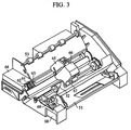
- Fig. 3 is a drawing showing an example of a liquid-jet recording apparatus including a multi-head.
- Figs. 4A to 4C are drawings respectively showing steps of a method of manufacturing a liquid-jet recording head of the present invention.
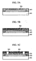
- Figs. 5A to 5C are drawings respectively showing steps performed after the steps shown in Fig. 4C.
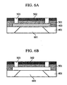
- Fig. 6A and 6B are drawings respectively showing steps performed after the steps shown in Fig. 5C.
- An epoxy resin composition of the present invention comprises (a) an epoxy resin having at least two alicyclic epoxy groups, at least one perfluoroalkyl group having 6 to 12 carbon atoms, and at least one alkylsiloxane group; and (b) a cationic polymerization catalyst.
- the alicyclic epoxy groups and the perfluoroalkyl group are present in branch chains of the epoxy resin, and the alkylsiloxane group is present in the main chain of the epoxy resin.
- the epoxy resin of the epoxy resin composition is not limited as long as the above conditions are satisfied.
- Examples of the epoxy resin of the present invention include epoxy resins represented by formula (1):
- a is an integer from 1 to 50
- b is an integer from 1 to 50
- c is an integer from 2 to 100.
- each of n 1 , n 2 , n 3 , n 5 , n 6 , and n 7 is an integer from 1 to 5
- n 4 is an integer from 2 to 200.
- each of R 1 , R 4' R 5 , R 6 , R 7 , and R 10 is independently a hydrogen atom or a straight or branched chain alkyl group having 1 to 3 carbon atoms
- each of R 2 , R 3 , R 8 and R 9 is independently a hydrogen atom, a straight or branched chain alkyl group having 1 to 3 carbon atoms, or a nitrile group
- R f is a straight or branched chain perfluoroalkyl group having 6 to 12 carbon atoms, particularly a perfluoroalkyl group having 8 to 10 carbon atoms.
- the epoxy resin represented by formula (1) can be obtained by copolymerization of perfluoroalkyl methacrylate, 3,4-oxycyclohexylmethyl methacrylate, and an azo group-containing polysiloxaneamide at an appropriate monomer ratio according to an ordinary method.
- the epoxy resin may also be commercially obtained.
- the epoxy resin can be synthesized by heating, light irradiation or heating and light irradiation of a compound represented by structural formula (1)-i below in coexistence with vinyl monomers represented by structural formulae (1)-ii and (1)-iii so as to produce radical species.
- R 1 to R 13 are the same as R 2 , R 3 , R 8 and R 9 above, n 8 and n 9 each represent 0 or an integer from 1 to 6, and X represents a halogen atom.
- R 1 , R 10' n 1' and n 7 are the same as defined above.
- a compound represented by formula (1)-i can be synthesized by the method disclosed in, for example, Japanese Patent Publication No JP-B-2-33053 ( JP-A-61252230 ). Namely, the compound can be obtained by reaction of a diamine represented by formula (1)-iv below and dihalides represented by formulae (1)-v and (1)-vi below.
- the epoxy resin composition represented by formula (1) preferably has a number average molecular weight of 8,000 to 22,000, and more preferably has a number average molecular weight of 8,500 to 20,000 in light of the durability of the water-repellent coating.
- An example of the epoxy resin represented by formula (1) is an epoxy resin represented by formula (2) below.
- R f , n 4 , and a, b and c are defined as above.
- a is 20 to 50
- b is 5 to 40
- c is 20 to 70
- n is 20 to 150
- the number average molecular weight is 8,000 to 20,000.
- a more preferred example of the epoxy resin is an acrylic epoxy resin (A-1) having a number average molecular weight of about 20,000 and represented by the following structural formula in which the monomer unit a is 40 mol%, the monomer unit b is 20 mol%, and the monomer unit c is 40 mol%:
- a 3,4-epoxycyclohexyl group is shown as an alicyclic epoxy group.
- the alicyclic group is not limited to this, and a cyclopropyl group or cyclohexyl group may be introduced.
- the epoxy resin may be used independently. Since the resin has a high molecular weight, the resin is preferably mixed with an oligomer having a lower molecular weight of the resin and a solvent to improve coating performance for a substance to be treated with the resin composition and to improve the drying property of a film after the solvent is evaporated, thereby improving the workability of treatment. Namely, the resin represented by formula (1) or another high molecular weight resin is preferably used to function as a binder. The resin represented by formula (1) or other high molecular weight resin is preferably used as the binder for exposure work in the form of a pattern on a resin film.
- the oligomer is preferably a resin having a lower molecular weight than the resin represented by formula (1), but another low molecular weight oligomer may be used.
- the resin composition of the present invention mainly comprises the epoxy resin represented by formula (1) and the catalyst
- the resin composition preferably further contains at least one compatibilizer according to demand.
- Preferred examples of the compatibilizer include compounds represented by the following formula (3) and (4): wherein p is an integer from 0 to 2.
- a preferred example of this compound is a compound where p is 0, i.e., 2,2-bis(4-glycidyloxyphenyl)hexafluoropropane. wherein q is an integer from 0 to 2, and
- a preferred example of this compound is a compound where q is 0, i.e., m-bis-[1-(2,3-epoxypropoxy)-2,2,2-trifluoro-1-(trifluoromethyl)ethyl]benzene.
- the compound represented by formula (3) or (4) has a fluoroalkyl group, and thus the film formed by using such a compound only minimally decreases the surface energy and has low water repellency and ink repellency because of its short chain length.
- the compound represented by formula (3) or (4) can be synthesized by reaction of a divalent alcohol and epichlorohydrin corresponding to a compound in which groups containing the epoxy groups at both ends are removed from the compound represented by general formula (3) or (4) by an ordinary method.
- the resin composition of the present invention contains a polymerization initiator as a catalyst for curing the resin composition.
- the resin composition is designed so as to have high reactivity to an onium salt of a Lewis acid which is activated by an active energy ray permitting curing at low temperature. Therefore, the surface of a substrate can be selectively treated by a photolithography method using the resin composition, and the resin composition is suitable for surface modification of a substrate which cannot be easily maintained at high temperature.
- the catalyst include bis(4-tert-butylphenyl)iodonium salt, Optomer SP-150 and Optomer SP-170 (trade name, produced by Asahidenka Kogyo Co., Ltd.), and the like.
- Optomer SP-150 The chemical structure of Optomer SP-150 is represented by the following formula:
- Optomer SP-170 The chemical structure of Optomer SP-170 is represented by the following formula:
- Irgacure 261 (trade name, produced by Chiba Specialty Co., Ltd.) represented by the following structural formula, and the like can also be used as the polymerization initiator:
- the resin composition of the present invention is preferably combined with an epoxy polymer which can participate in a cross-linking reaction by itself, as a binder polymer other than the resin represented by formula (1).
- a polymer include an acrylic resin obtained by copolymerization of an acryl monomer having a side chain epoxy group, a vinyl polymer obtained by polymerization of a vinyl monomer having an alicyclic epoxy group in its side chain, a polyester polymer having an alicyclic epoxy group in its side chain (for example, EHPE3150, produced by Daicel Chemical Industries, Ltd.), and the like. If a polymer without such an epoxy group is used, physical properties are intentionally controlled according to the application thereof.
- polymers of such a polymer include general purpose polymer compounds for coating, such as polymers of bisphenol epoxy resins (trade names PKHC and PKHJ, produced by Union Carbide Co., Ltd.), poly(ethylene/vinyl acetate), phenol resins, polycarbonate resins, polyester resins, polyamide resins, soluble polyimide resins, and the like.
- the epoxy resin composition of the present invention basically contains the components below in a nonpolar solvent.
- the mixing ratio depends upon the softening point and glass transition temperature of both components, and thus the ratio is not generally limited.
- the ratio of oligomer : component (a) is 10:90 to 90:10 (ratio by mass).
- the ratio of the catalyst (b) is in the range of 0.5 part by mass to 7 parts by mass relative to 100 part by mass of the total amount of the epoxy resin components.
- the oligomer has low compatibility with the polymer, and thus the compatibilizer (c) is preferably used.
- the epoxy resin composition of the present invention is used for treating the surface of a substrate by heating or irradiation with an active energy ray.
- the resin composition of the present invention is dissolved in an aromatic solvent, an aliphatic hydrocarbon solvent, an ester solvent, an ether solvent, a fluorocarbon solvent, or the like, and the resultant solution can be coated on the surface of the substrate by any one of various coating/printing methods such as roll coating, spin coating, spray coating, screen printing, gravure printing, etc.
- the formed film is cured by heating or irradiation with an active energy ray.
- a source of an active energy ray for curing a mercury lamp, a laser beam, an electron beam, or the like, which contains large amounts of bright line spectra in the range of wavelengths from 200 to 480 nm, is preferred.
- the epoxy resin composition of the present invention preferably contains the binder component and is prepared so as to form a dry solid film.
- the epoxy resin composition can facilitate selective surface treatment of the substrate by patterning similar to a photoresist process.
- a coating solution containing the resin composition of the present invention is coated on the substrate, and then the solvent is removed to form a dry film.
- the film is irradiated with an active energy ray through a mask having an appropriate pattern or irradiated with an active energy ray in the form of a pattern, and then the uncured portion of the film is removed by development with a solvent system which can dissolve the film.
- post-curing is preferably performed after development.
- an energy source for post-curing heating with a microwave or the like or an active energy ray irradiation by an electron beam, ultraviolet rays, or the like is used.
- the above-described surface modifying method of the present invention enables water-repellent and oil-repellent treatment with excellent film adhesion to the substrate and surface hardness of the film, and thus has the great advantage that the substrate can be modified to have excellent durability.
- the nozzle surface of the liquid-jet recording head is treated with the resin composition of the present invention to form a surface which exhibits no strong adhesion of an ink and which has good release property, facilitating wiping of the ink adhering to the nozzle surface by a cleaning operation.
- a cleaning mechanism may be mounted on the liquid-jet recording head, for example, the ink-jet recording head, or a cleaning method may be performed.
- the ink adhering to the orifice surface of the ink-jet recording head may be wiped with a rubber blade, the ink in a nozzle may be sucked by a pump, or the ink may be discharged at a position other than on a recording sheet.
- Any one of these methods cannot eliminate the phenomenon that small droplets of excessive ink adhere to the periphery of the nozzle because not all of the ink is turned into ink droplets when an ink column withdrawn by discharge pressure forms into a droplet. Therefore, if the small droplets spontaneously drop, are sucked back to the inside of the nozzle, or are readily removed, the droplets have no influence on ink discharge.
- the epoxy resin composition of the present invention can be cured at relatively low temperature to provide a cured film having excellent water repellency, oil repellency, adhesion to the substrate, chemical resistance, and friction resistance.
- Figs. 1 and 2 show the principal portion of an example of the construction of a liquid-jet recording head to which the resin composition of the present invention can be applied.
- Fig. 1 is a sectional view taken along a flow path of an ink
- Fig. 2 is a perspective view of the liquid-jet recording head shown in Fig. 1.
- the recording head 13 shown in Fig. 1 comprises a substrate 15 on which a discharge energy generator (17, 18, 19) is disposed, and a member 14 laminated on the substrate 15 by forming a predetermined pattern of a cured product of a thermosetting resin composition and/or an active energy ray curing resin composition to form at least a flow path.
- the substrate 15 comprises a base 20 made of a material with a high heat release effect, such as alumina or the like, and a heat storage layer 19, an exothermic resistor layer 18 made of a metal, electrodes 17-1 and 17-2 made of aluminum or the like, and a protective layer 16, which are laminated, in that order, on the surface of the base 20.
- the discharge energy generating element formed in a portion (in the region shown by character n in Fig. 1) of the exothermic resistor layer 18, in which the electrodes are not formed generates heat to exert thermal energy on an ink positioned above the element.
- a cured film 30 comprising the resin composition of the present invention is used as a water-repellent and ink-repellent agent in the peripheries of at least the orifice openings 22 of the orifice surface 29 (Fig. 2), thereby preventing the droplets from adhering to the surface to prevent a deviation in the discharge direction of the droplets.
- the cured film comprising the resin composition of the present invention not only exhibits excellent adhesion to the substrate, but also causes no deterioration in water repellency and adhesion even when the ink contains an organic solvent, particularly, a polar organic solvent.
- Fig. 3 shows an example of a liquid-jet recording apparatus including such a multi-head as shown in Fig. 2.
- reference numeral 61 denotes a blade serving as a wiping member, one end of which is a fixed end held by a blade holding member to establish a cantilever state.
- the blade 61 is disposed at a position adjacent to a recording region of the recording head. In this example, the blade 61 is held to project into the movement path of the recording head.
- Reference numeral 62 denotes a cap disposed at a home position adjacent to the blade 61 and is moved perpendicularly to the movement direction of the recording head to cap the orifices in contact therewith.
- reference numeral 63 denotes an ink absorber provided adjacent to the blade 61 and held to project into the movement path of the recording head in the same manner as the blade 61.
- the blade 61, the cap 62 and the ink absorber 63 constitute a discharge recovery section 64 for removing moisture, dust particles, and the like from the ink discharge orifice surface by the blade 61 and the ink absorber 63.
- Reference numeral 65 denotes a recording head for recording in a liquid-jet system, for example, having a construction in which an ink is discharged by thermal energy, as shown in Figs. 1 and 2.
- Reference numeral 66 denotes a carriage for moving the recording head 65 mounted thereon.
- the carriage 66 is slidably engaged with a guide shaft 67 and partially connected (not shown in the drawing) to a belt 69 driven by a motor 68. Therefore, the carriage 66 can be moved along the guide shaft 67, i.e., can be moved to the recording region of the recording head 65 and the adjacent region thereof.
- Reference numeral 51 denotes a paper feed section into which a recording medium is inserted
- reference numeral 52 denotes a paper feed roller driven by a motor not shown in the drawing. This construction permits the recording medium to be fed to a position opposite to the discharge orifice surface of the recording head and expelled through a paper-expelling roller 53 as recording proceeds.
- the cap 65 of the head recovery section 64 retreats from the movement path of the recording head 65, while the blade 61 projects into the movement path. As a result, the orifice surface of the recording head 65 is wiped.
- the cap 62 is moved to project into the movement path of the recording head 65.
- the recording head 65 When the recording head 65 is moved from the home position to the start position of recording, the cap 62 and the blade 61 are at the same positions as at the time of wiping. As a result, in this movement, the orifice surface of the recording head 65 is wiped.
- the recording head 65 is moved to the home position at the times of recording end and recovery, but the recording head 65 is also moved to the home position adjacent to the recording region of the recording head at predetermined intervals when the recording head 65 is moved in the recording region for recording. During this movement, the discharge surface is also wiped.
- the ink jet recording apparatus can use a recording head in which discharge orifices for cyan, magenta, yellow and black inks are arranged in parallel.
- recording heads for the respective colors may be arranged in parallel.
- each of the color inks may be discharged from one discharge orifice or simultaneously discharged from a plurality of discharge orifices to adhere at least two droplets of the same color to the recording medium.
- the liquid-jet recording head of the present invention is subjected to surface treatment with an ink repellent treatment material comprising the above-described epoxy resin composition of the present invention and has the chemical properties described in the examples below. Therefore, an ink adheres less, or adhered ink can be easily removed by a cleaning wiper blade, thereby significantly improving substantial retention of a print.
- the epoxy resin composition of the present invention used in this method is dissolved in an organic solvent and used in the form of a coating solution.
- a coating thickness of as small as several ⁇ m an ordinary fine coating device such as a roll coater, a spin coater, a spray coater, or the like can be used.
- the coating solution may be coated on a release sheet to form a dry film, and the dry film may be bonded to the surface of a substrate using a laminator or the like to form a film on the surface of the substrate.
- a first method of treating the surface of the substrate in the form of a pattern can be achieved by selectively irradiating the film with an active energy ray through a mask having a predetermined pattern and then performing development with a developer to remove uncured portions of the film.
- a solvent or a solvent composition suitable for the film comprising the resin composition of the present invention must be selected as the developer.
- the developer any one of aromatic hydrocarbons, ketones, esters, glycol ethers, and the like, and mixtures thereof can be used.
- heating or active energy ray irradiation is preferably performed as post-curing after development.
- a second method of treating the surface of the substrate in the form of a pattern comprises the first step (1) of coating the coating solution on the substrate and drying the coating to form a film, the second step (2) of irradiating the whole surface with an active energy ray which accelerates polymerization to cure the film, and the third step (3) of irradiating the film with a decay active energy ray to selectively remove a desired portion of the cured-portion of the film.
- the active energy ray for accelerating polymerization ultraviolet rays rich in light at wavelengths from 250 to 480 ⁇ m can be used.
- the decay active energy ray light at wavelengths of 210 ⁇ m or less, an excimer laser, or the like can be used.
- the film in order to complete curing of the film, is preferably heat-treated or irradiated with a polymerizing active energy ray in any one of the steps.
- the epoxy resin composition of the present invention is useful as a water repellent agent or water repellent coating material applied to a surface which may come into contact with a solution or a material containing a component such as a polar organic solvent, which deteriorates the adhesion of the water repellent agent.
- the epoxy resin composition can also be used for water repellent and ink repellent treatment of the discharge orifice surface of the liquid-jet recording head.
- Resin A-1:Optomer AP-170 96:4 (used in Example 1 below)
- Resin A-1:Optomer AP-170 94:6 (used in Example 2 below)
- Resin A-1:0ptomer AP-170:1,4-bis(2-hydroxyhexafluoroisopropyl)benzene 95:5:25 (used in Example 3 below)
- Resin A-1:Optomer AP-170:1,4-bis(2-hydroxyhexafluoroisopropyl)benzene:2,2-bis(4-glycidyloxyphenyl)hexafluoropropane 80:5:25:25 (used in Example 4 below)
- each of Composition Examples 1 to 4 was added to diethylene glycol dimethyl ether as a solvent and dissolved therein to form a 30% to 40% solution. Then, each of the prepared solutions was applied to a silicon wafer substrate having a 5- ⁇ m thick thermally oxidized film by means of a spinner to have a thickness of 1 to 3 ⁇ m in a wet state. Then, the substrate was dried on a hot plate at 110°C for 5 minutes to remove the solvent. Then, the substrate was irradiated with ultraviolet rays to an accumulated dose of 2 J/cm 2 by means of an ultraviolet ray irradiation apparatus using a high-pressure mercury lamp. Thereafter, the substrate was heated in a furnace at 150°C for 15 minutes to complete the curing reaction. The thus-formed four substrates were measured as described below. T1: Measurement of contact angle
- T2 Measurement of contact angle after immersion in a water dispersion of dye
- T3 Long-term printing durability
- positive type photoresist (trade name ODUR-1010, produced by Tokyo Ohka Kogyo Co., Ltd.) was coated to a thickness of 13 ⁇ m on a substrate 401 to be treated; the substrate had been previously provided with discharge energy generating elements 402, by spin coating to form a resist layer 403, as shown in Fig. 4C. Then, an epoxy resin composition having the composition shown in Table 1 was deposited to a thickness of 25 ⁇ m as a flow path forming material 501 on the resist layer 403, as shown in Fig. 5A.
- the flow path forming material layer 501 was deposited, it was dried at 80°C on a hot plate for 3 minutes. Then, a solution of each of Examples 1 to 4, respectively containing Composition Examples 1 to 4, was coated on the deposited layer by spin coating to form a film 502, as shown in Fig. 5B.
- the thus-formed first (501) and second (502) photosensitive resin layers were exposed to ultraviolet rays of 1.0 J/cm 2 through a mask having the pattern of a discharge orifice portion using Canon mask analyzer MPA600, heat-treated at 90°C for 4 minutes, and then immersed in a developer containing MIBK and xylene at a ratio of 2:3 to form discharge orifices 503 (Fig. 5C).
- an ink supply port 601 was formed at the back of the Si substrate 401 by anisotropic etching, and, as shown in Fig. 6B, the resist layer 403 was finally removed. Furthermore, the first (501) and second (502) photosensitive resin layers were heat-treated at 200°C for 1 hour for the purpose of completely curing the layers to-complete nozzles.
- the thus-obtained nozzles were incorporated into an ink-jet recording head and electrically wired in a predetermined manner.
- the ink-jet recording head was mounted in a printer, and a long-term printing durability test was conducted using an ink-jet ink comprising pure water, glycerin, food black 2 (water-soluble black dye), and N-methylpyrrolidone at a ratio of 70:15:3:12 (parts by mass).
- each of the measurements T1 to T3 was performed by the same method as in Example 1, except that bisphenol AF (the structure below), which is a fluorine-containing epoxy resin, was used in place of the epoxy resin of Example 1.
- Flurorad TM FC-722 fluoro-coating agent, produced by Sumitomo 3M
- FC-722 fluoro-coating agent, produced by Sumitomo 3M
- the surface of the resultant coating was treated by drying at 100°C for 30 minutes.
- this plate was irradiated with an exicmer laser at a wavelength of 195 ⁇ m, which was converged to a beam diameter of 5 ⁇ m, from above to form a nozzle opening.
- a film comprising the resin composition of the present invention exhibits a large contact angle and excellent durability. Therefore, an ink would not adhere to the surface of the printing head even if the surface is held in contact with an ink for a long period of time so that ink droplets have excellent landing precision, and a high printing quality could be maintained for a long period of time.
- composition Examples 1 and 3 were coated on a molded plate of polyether sulfone using a spinner so that the thickness after evaporation of the solvent was about 2 ⁇ m and then dried. Then, this plate was irradiated with light with a total of 10 J/cm 2 from a high-pressure mercury lamp to perform polymerization curing of the film. Then, the plate was irradiated with an excimer laser at a wavelength of 195 ⁇ m, which was converged to a beam diameter of 5 ⁇ m, from above to form a nozzle opening. The opening was satisfactorily formed, and no decomposition residue was produced at the edge. As a result, it was found that the composition of the present invention has excellent suitability to processing with an ultraviolet laser,
- a resin composition suitable as a water-repellent agent or water-repellent coating material which can be applied to a surface which is apt to be brought into contact with a solution or substance containing a component that can damage the film forming property and adhesion of the water-repellent agent.
- a resin composition permitting surface modifying treatment, thereby making it possible to maintain in clear state.
- an ink-jet recording head and liquid-jet recording apparatus in which the surface of a nozzle can be maintained in a clear state by treating the substrate with the resin composition of the present invention so that ink would not adhere to the surface of a printing head even if it is in contact with the ink for a long period of time, thereby improving the landing precision of dots, and maintaining a print quality for a long time.
- An epoxy resin composition can be used for forming a film having excellent water-repellency on a substrate surface.
- the epoxy resin composition contains (a) an epoxy resin having at least two alicyclic epoxy groups, at least one perfluoroalkyl group having 6 to 12 carbon atoms, and at least one alkylsiloxane group and (b) a cationic polymerization catalyst.
- the alicyclic epoxy groups and the perfluoroalkyl group are present in branched chains of the epoxy resin, and the alkylsiloxane group is present in the main chain of the epoxy resin.
Landscapes
- Chemical & Material Sciences (AREA)
- Manufacturing & Machinery (AREA)
- Engineering & Computer Science (AREA)
- Polymers & Plastics (AREA)
- Chemical Kinetics & Catalysis (AREA)
- Medicinal Chemistry (AREA)
- Health & Medical Sciences (AREA)
- Organic Chemistry (AREA)
- Particle Formation And Scattering Control In Inkjet Printers (AREA)
- Epoxy Resins (AREA)
- Paints Or Removers (AREA)
- Application Of Or Painting With Fluid Materials (AREA)
- Ink Jet Recording Methods And Recording Media Thereof (AREA)
Applications Claiming Priority (2)
| Application Number | Priority Date | Filing Date | Title |
|---|---|---|---|
| JP2002008439 | 2002-01-17 | ||
| JP2002008439 | 2002-01-17 |
Publications (3)
| Publication Number | Publication Date |
|---|---|
| EP1333046A2 EP1333046A2 (en) | 2003-08-06 |
| EP1333046A3 EP1333046A3 (en) | 2004-09-08 |
| EP1333046B1 true EP1333046B1 (en) | 2007-08-01 |
Family
ID=19191421
Family Applications (1)
| Application Number | Title | Priority Date | Filing Date |
|---|---|---|---|
| EP03000968A Expired - Lifetime EP1333046B1 (en) | 2002-01-17 | 2003-01-16 | Epoxy resin composition, surface treatment method, liquid-jet recording head and liquid-jet recording apparatus |
Country Status (7)
Families Citing this family (26)
| Publication number | Priority date | Publication date | Assignee | Title |
|---|---|---|---|---|
| CN1208388C (zh) * | 2002-01-17 | 2005-06-29 | 佳能株式会社 | 环氧树脂组合物、表面处理方法、液体喷射记录头和液体喷射记录装置 |
| ES2316877T3 (es) * | 2003-07-22 | 2009-04-16 | Leibniz-Institut Fur Neue Materialien Gemeinnutzige Gmbh | Composicion de recubrimiento repelente a liquidos conresistencia a los alcalis y recubrimiento que se pueda usar en procedimientos de formacacion de patrones. |
| AU2003254564A1 (en) * | 2003-07-22 | 2005-02-25 | Canon Kabushiki Kaisha | Liquid-repellent coating composition and coating having high alkali resistance |
| CN101068845B (zh) * | 2004-12-03 | 2010-05-26 | 三菱化学株式会社 | 组合物、固化物和物品 |
| DE102005002960A1 (de) * | 2005-01-21 | 2006-08-03 | Leibniz-Institut Für Neue Materialien Gemeinnützige Gmbh | Kompositzusammensetzung für mikrogemusterte Schichten mit hohem Relaxationsvermögen, hoher chemischer Beständigkeit und mechanischer Stabilität |
| EP1801142B1 (en) | 2005-12-16 | 2016-02-24 | Canon Kabushiki Kaisha | Resin composition,resin cured product, and liquid discharge head |
| CN100556954C (zh) * | 2006-06-05 | 2009-11-04 | 中国科学院化学研究所 | 发光二级管封装用耐紫外和高温老化的有机硅环氧树脂组合物 |
| WO2008000680A1 (en) * | 2006-06-27 | 2008-01-03 | Clariant International Ltd | Fluorous telomeric compounds and polymers containing same |
| DE102006033280A1 (de) * | 2006-07-18 | 2008-01-24 | Leibniz-Institut Für Neue Materialien Gemeinnützige Gmbh | Kompositzusammensetzung für mikrostrukturierte Schichten |
| JP4865473B2 (ja) * | 2006-09-25 | 2012-02-01 | 富士フイルム株式会社 | 成形印刷物の製造方法、及び、成形印刷物 |
| KR20080067925A (ko) * | 2007-01-17 | 2008-07-22 | 삼성전자주식회사 | 잉크젯 프린트헤드 및 그 제조방법 |
| JP2009143048A (ja) * | 2007-12-12 | 2009-07-02 | Tdk Corp | ハードコート層および光透過層を有する積層体およびその製造方法 |
| JP5315681B2 (ja) * | 2007-12-12 | 2013-10-16 | Tdk株式会社 | ハードコート用組成物、ハードコート層を有する物体およびその製造方法 |
| US8563115B2 (en) * | 2008-08-12 | 2013-10-22 | Xerox Corporation | Protective coatings for solid inkjet applications |
| US8191992B2 (en) * | 2008-12-15 | 2012-06-05 | Xerox Corporation | Protective coatings for solid inkjet applications |
| JP5726181B2 (ja) * | 2010-05-27 | 2015-05-27 | 昭和電工株式会社 | フッ素及びエポキシ基含有共重合体及びその製造方法 |
| JP5783854B2 (ja) * | 2011-09-01 | 2015-09-24 | キヤノン株式会社 | 液体吐出ヘッドの製造方法、および液体吐出ヘッド |
| KR101482687B1 (ko) * | 2013-02-20 | 2015-01-16 | 한국과학기술원 | 투명 플렉시블 하드코팅 필름, 및 이의 제조 방법 |
| US10246606B2 (en) | 2013-02-20 | 2019-04-02 | Korea Advanced Institute Of Science And Technology | Transparent flexible hard coated film and method of producing the same |
| US20140303284A1 (en) * | 2013-03-15 | 2014-10-09 | The Sherwin-Williams Company | Expoxyfluorosilicones and modified polyacrylic resins for coating compositions |
| USD728577S1 (en) * | 2014-07-01 | 2015-05-05 | Google Inc. | Mobile device module |
| USD730906S1 (en) * | 2014-07-01 | 2015-06-02 | Google Inc. | Mobile device module |
| JP6991806B2 (ja) * | 2017-09-14 | 2022-01-13 | 東芝テック株式会社 | インクジェットヘッド及びインクジェットプリンタ |
| JP2019051636A (ja) * | 2017-09-14 | 2019-04-04 | 東芝テック株式会社 | インクジェットヘッド及びインクジェットプリンタ |
| JP7098350B2 (ja) | 2018-02-28 | 2022-07-11 | キヤノン株式会社 | 接着シートを用いたインクジェット記録ヘッド及び製造方法 |
| JP7077774B2 (ja) * | 2018-05-23 | 2022-05-31 | 信越化学工業株式会社 | 活性エネルギー線硬化性組成物 |
Family Cites Families (36)
| Publication number | Priority date | Publication date | Assignee | Title |
|---|---|---|---|---|
| JPH0233053B2 (ja) | 1985-04-30 | 1990-07-25 | Osaka City | Azokiganjuhorishirokisanamido |
| US4688052A (en) * | 1985-07-13 | 1987-08-18 | Canon Kabushiki Kaisha | Liquid jet recording head having a layer of a resin composition curable with an active energy ray |
| US4688053A (en) * | 1985-07-13 | 1987-08-18 | Canon Kabushiki Kaisha | Liquid jet recording head having a layer of a resin composition curable with an active energy ray |
| JPH0639166B2 (ja) * | 1985-09-12 | 1994-05-25 | キヤノン株式会社 | 記録器具 |
| JPH0698759B2 (ja) * | 1986-10-13 | 1994-12-07 | キヤノン株式会社 | 液体噴射記録ヘツド |
| JPH0698760B2 (ja) * | 1986-10-13 | 1994-12-07 | キヤノン株式会社 | 液体噴射記録ヘツド |
| IT1199770B (it) | 1986-12-16 | 1988-12-30 | Ausimont Spa | Resine epossidiche ottenute mediante coreticolazione di prepolimeri epossidici fluorurati e prepolimeri epossidici non fluorurati |
| US4954580A (en) | 1987-12-01 | 1990-09-04 | Ciba-Geigy Corporation | Epoxysiloxanes |
| JPH0284343A (ja) * | 1988-03-16 | 1990-03-26 | Canon Inc | 液体噴射記録ヘッド |
| JPH0233053A (ja) | 1988-07-22 | 1990-02-02 | Nec Corp | 紙幣自動取扱装置 |
| JP2593922B2 (ja) | 1988-07-30 | 1997-03-26 | キヤノン株式会社 | インクジエット記録ヘッド |
| EP0368320B1 (en) | 1988-11-10 | 1997-10-08 | Dai Nippon Insatsu Kabushiki Kaisha | Heat transfer image-receiving sheet |
| US5086307A (en) * | 1990-03-21 | 1992-02-04 | Canon Kabushiki Kaisha | Liquid jet recording head |
| US5178959A (en) | 1991-03-27 | 1993-01-12 | General Electric Company | Epoxy-functional fluorosilicones |
| US5196558A (en) * | 1991-08-07 | 1993-03-23 | Shin-Etsu Chemical Company, Limited | Siloxane compounds |
| JP2975190B2 (ja) * | 1991-10-29 | 1999-11-10 | キヤノン株式会社 | インクジェット記録ヘッド |
| ATE141546T1 (de) * | 1991-10-31 | 1996-09-15 | Canon Kk | Polymerzusammensetzung für transfer-giessen zur herstellung eines farbstrahlaufzeichnungskopfes und unter deren verwendung hergestellter farbstrahlaufzeichnungskopf |
| CA2092458A1 (en) | 1992-05-29 | 1993-11-30 | Richard P. Eckberg | Fluoro-organo modified uv-curable epoxy silicone and epoxyfluorosilicone compositions |
| JP3061944B2 (ja) * | 1992-06-24 | 2000-07-10 | キヤノン株式会社 | 液体噴射記録ヘッド、その製造方法及び記録装置 |
| JP3274031B2 (ja) * | 1993-10-13 | 2002-04-15 | キヤノン株式会社 | インクジェットヘッドおよび該インクジェットヘッドを備えたインクジェット装置 |
| JP3397478B2 (ja) * | 1993-11-26 | 2003-04-14 | キヤノン株式会社 | インクジェットヘッド及び該インクジェットヘッドの製造方法及びインクジェット装置 |
| JPH08301954A (ja) | 1995-04-28 | 1996-11-19 | Toray Dow Corning Silicone Co Ltd | 硬化性剥離剤組成物 |
| WO1996041835A1 (fr) * | 1995-06-13 | 1996-12-27 | Canon Kabushiki Kaisha | Composition de resine epoxyde a base de fluor tres soluble dans des solvants |
| US5980026A (en) * | 1995-06-14 | 1999-11-09 | Canon Kabushiki Kaisha | Process for production of ink jet head |
| JPH09132657A (ja) * | 1995-09-04 | 1997-05-20 | Canon Inc | 基材の表面処理方法及び該方法を用いたインクジェット記録ヘッドの製造方法 |
| JPH09239992A (ja) * | 1996-03-12 | 1997-09-16 | Canon Inc | 液体噴射記録ヘッド、その製造方法、及び該ヘッドを有する液体噴射記録装置 |
| JP3559697B2 (ja) | 1997-12-01 | 2004-09-02 | キヤノン株式会社 | インクジェット記録ヘッドの製造方法 |
| US6409931B1 (en) * | 1998-01-26 | 2002-06-25 | Canon Kabushiki Kaisha | Method of producing ink jet recording head and ink jet recording head |
| US6472129B2 (en) | 1998-03-10 | 2002-10-29 | Canon Kabushiki Kaisha | Fluorine-containing epoxy resin composition, and surface modification process, ink jet recording head and ink jet recording apparatus making use of the same |
| US6139920A (en) * | 1998-12-21 | 2000-10-31 | Xerox Corporation | Photoresist compositions |
| US6586495B1 (en) * | 1999-09-20 | 2003-07-01 | Canon Kabushiki Kaisha | Alkylsiloxane-containing epoxy resin composition, surface modifying method using the same, ink-jet recording head and liquid-jet recording apparatus |
| JP4033286B2 (ja) * | 2001-03-19 | 2008-01-16 | 日本板硝子株式会社 | 高屈折率誘電体膜とその製造方法 |
| US6750290B2 (en) * | 2001-04-19 | 2004-06-15 | Canon Kabushiki Kaisha | Epoxy resin composition, method of improving surface of substrate, ink jet recording head and ink jet recording apparatus |
| US6846520B2 (en) * | 2002-01-17 | 2005-01-25 | Canon Kabushiki Kaisha | Epoxy resin composition, surface treatment method, liquid-jet recording head and liquid-jet recording apparatus |
| CN1208388C (zh) * | 2002-01-17 | 2005-06-29 | 佳能株式会社 | 环氧树脂组合物、表面处理方法、液体喷射记录头和液体喷射记录装置 |
| US6869541B2 (en) * | 2002-02-21 | 2005-03-22 | Canon Kabushiki Kaisha | Epoxy resin composition, surface treating method, ink-jet recording head, and ink-jet recording apparatus |
-
2003
- 2003-01-13 US US10/340,708 patent/US6992117B2/en not_active Expired - Fee Related
- 2003-01-14 CN CNB031004423A patent/CN1208389C/zh not_active Expired - Fee Related
- 2003-01-16 AT AT03000968T patent/ATE368697T1/de not_active IP Right Cessation
- 2003-01-16 ES ES03000968T patent/ES2287366T3/es not_active Expired - Lifetime
- 2003-01-16 EP EP03000968A patent/EP1333046B1/en not_active Expired - Lifetime
- 2003-01-16 DE DE60315205T patent/DE60315205T2/de not_active Expired - Lifetime
- 2003-01-16 KR KR1020030002999A patent/KR100626782B1/ko not_active IP Right Cessation
-
2005
- 2005-06-27 US US11/166,124 patent/US7399502B2/en not_active Expired - Fee Related
Non-Patent Citations (1)
| Title |
|---|
| None * |
Also Published As
| Publication number | Publication date |
|---|---|
| EP1333046A3 (en) | 2004-09-08 |
| KR100626782B1 (ko) | 2006-09-22 |
| DE60315205D1 (de) | 2007-09-13 |
| KR20030063165A (ko) | 2003-07-28 |
| CN1208389C (zh) | 2005-06-29 |
| US20050267265A1 (en) | 2005-12-01 |
| DE60315205T2 (de) | 2008-05-08 |
| EP1333046A2 (en) | 2003-08-06 |
| US6992117B2 (en) | 2006-01-31 |
| US7399502B2 (en) | 2008-07-15 |
| ATE368697T1 (de) | 2007-08-15 |
| CN1432601A (zh) | 2003-07-30 |
| ES2287366T3 (es) | 2007-12-16 |
| US20030169313A1 (en) | 2003-09-11 |
Similar Documents
| Publication | Publication Date | Title |
|---|---|---|
| US7399502B2 (en) | Composition of perfluoroalkyl group-containing alkylsiloxy cycloaliphatic epoxy resin | |
| US7566758B2 (en) | Epoxy resin composition | |
| EP1783153B1 (en) | Surface modification process making use of a fluorine-containing epoxy resin composition. | |
| US6869541B2 (en) | Epoxy resin composition, surface treating method, ink-jet recording head, and ink-jet recording apparatus | |
| US6750290B2 (en) | Epoxy resin composition, method of improving surface of substrate, ink jet recording head and ink jet recording apparatus | |
| US20030181623A1 (en) | Alkylsiloxane-containing epoxy resin composition, surface modifying method using the same, ink-jet recording head and liquid-jet recording apparatus | |
| US6448346B1 (en) | Fluorine-containing epoxy resin composition, and surface modification process, ink jet recording head and ink jet recording apparatus making use of the same | |
| US6344526B1 (en) | Fluorine-containing epoxy resin composition, and surface modification process, ink jet recording head and ink jet recording apparatus using same | |
| EP1329473B1 (en) | Epoxy resin composition, surface treatment method, liquid-jet recording head and liquid-jet recording apparatus | |
| JP4174124B2 (ja) | 含フッ素エポキシ樹脂組成物を用いた表面改質方法、インクジェット記録ヘッド、インクジェット記録装置 | |
| JP4174123B2 (ja) | 含フッ素エポキシ樹脂組成物及びこれを用いたインクジェット記録ヘッド | |
| JP4175620B2 (ja) | エポキシ樹脂組成物、及び液体噴射記録ヘッド | |
| JPH11335440A (ja) | 含フッ素エポキシ樹脂組成物及びこれを用いた表面改質方法、インクジェット記録ヘッド、インクジェット記録装置 | |
| JP4174329B2 (ja) | エポキシ樹脂組成物、及び液体噴射記録ヘッド | |
| JP4006346B2 (ja) | エポキシ樹脂組成物、これを用いた物品の表面の選択的処理方法及びインクジェット記録ヘッド | |
| JP2001158818A (ja) | 含アルキルシロキサンエポキシ樹脂組成物及びそれを用いた表面改質方法、インクジェット記録へッド、液体噴射記録装置 |
Legal Events
| Date | Code | Title | Description |
|---|---|---|---|
| PUAI | Public reference made under article 153(3) epc to a published international application that has entered the european phase |
Free format text: ORIGINAL CODE: 0009012 |
|
| AK | Designated contracting states |
Designated state(s): AT BE BG CH CY CZ DE DK EE ES FI FR GB GR HU IE IT LI LU MC NL PT SE SI SK TR |
|
| AX | Request for extension of the european patent |
Extension state: AL LT LV MK RO |
|
| PUAL | Search report despatched |
Free format text: ORIGINAL CODE: 0009013 |
|
| AK | Designated contracting states |
Kind code of ref document: A3 Designated state(s): AT BE BG CH CY CZ DE DK EE ES FI FR GB GR HU IE IT LI LU MC NL PT SE SI SK TR |
|
| AX | Request for extension of the european patent |
Extension state: AL LT LV MK RO |
|
| 17P | Request for examination filed |
Effective date: 20050119 |
|
| AKX | Designation fees paid |
Designated state(s): AT BE BG CH CY CZ DE DK EE ES FI FR GB GR HU IE IT LI LU MC NL PT SE SI SK TR |
|
| GRAP | Despatch of communication of intention to grant a patent |
Free format text: ORIGINAL CODE: EPIDOSNIGR1 |
|
| GRAS | Grant fee paid |
Free format text: ORIGINAL CODE: EPIDOSNIGR3 |
|
| GRAA | (expected) grant |
Free format text: ORIGINAL CODE: 0009210 |
|
| AK | Designated contracting states |
Kind code of ref document: B1 Designated state(s): AT BE BG CH CY CZ DE DK EE ES FI FR GB GR HU IE IT LI LU MC NL PT SE SI SK TR |
|
| REG | Reference to a national code |
Ref country code: GB Ref legal event code: FG4D |
|
| REG | Reference to a national code |
Ref country code: CH Ref legal event code: EP |
|
| REG | Reference to a national code |
Ref country code: IE Ref legal event code: FG4D |
|
| REF | Corresponds to: |
Ref document number: 60315205 Country of ref document: DE Date of ref document: 20070913 Kind code of ref document: P |
|
| REG | Reference to a national code |
Ref country code: ES Ref legal event code: FG2A Ref document number: 2287366 Country of ref document: ES Kind code of ref document: T3 |
|
| PG25 | Lapsed in a contracting state [announced via postgrant information from national office to epo] |
Ref country code: BG Free format text: LAPSE BECAUSE OF FAILURE TO SUBMIT A TRANSLATION OF THE DESCRIPTION OR TO PAY THE FEE WITHIN THE PRESCRIBED TIME-LIMIT Effective date: 20071101 Ref country code: FI Free format text: LAPSE BECAUSE OF FAILURE TO SUBMIT A TRANSLATION OF THE DESCRIPTION OR TO PAY THE FEE WITHIN THE PRESCRIBED TIME-LIMIT Effective date: 20070801 |
|
| REG | Reference to a national code |
Ref country code: CH Ref legal event code: PL |
|
| ET | Fr: translation filed | ||
| PG25 | Lapsed in a contracting state [announced via postgrant information from national office to epo] |
Ref country code: LI Free format text: LAPSE BECAUSE OF FAILURE TO SUBMIT A TRANSLATION OF THE DESCRIPTION OR TO PAY THE FEE WITHIN THE PRESCRIBED TIME-LIMIT Effective date: 20070801 Ref country code: CH Free format text: LAPSE BECAUSE OF FAILURE TO SUBMIT A TRANSLATION OF THE DESCRIPTION OR TO PAY THE FEE WITHIN THE PRESCRIBED TIME-LIMIT Effective date: 20070801 Ref country code: AT Free format text: LAPSE BECAUSE OF FAILURE TO SUBMIT A TRANSLATION OF THE DESCRIPTION OR TO PAY THE FEE WITHIN THE PRESCRIBED TIME-LIMIT Effective date: 20070801 |
|
| PG25 | Lapsed in a contracting state [announced via postgrant information from national office to epo] |
Ref country code: BE Free format text: LAPSE BECAUSE OF FAILURE TO SUBMIT A TRANSLATION OF THE DESCRIPTION OR TO PAY THE FEE WITHIN THE PRESCRIBED TIME-LIMIT Effective date: 20070801 |
|
| PG25 | Lapsed in a contracting state [announced via postgrant information from national office to epo] |
Ref country code: DK Free format text: LAPSE BECAUSE OF FAILURE TO SUBMIT A TRANSLATION OF THE DESCRIPTION OR TO PAY THE FEE WITHIN THE PRESCRIBED TIME-LIMIT Effective date: 20070801 Ref country code: GR Free format text: LAPSE BECAUSE OF FAILURE TO SUBMIT A TRANSLATION OF THE DESCRIPTION OR TO PAY THE FEE WITHIN THE PRESCRIBED TIME-LIMIT Effective date: 20071102 |
|
| PG25 | Lapsed in a contracting state [announced via postgrant information from national office to epo] |
Ref country code: PT Free format text: LAPSE BECAUSE OF FAILURE TO SUBMIT A TRANSLATION OF THE DESCRIPTION OR TO PAY THE FEE WITHIN THE PRESCRIBED TIME-LIMIT Effective date: 20080102 Ref country code: SK Free format text: LAPSE BECAUSE OF FAILURE TO SUBMIT A TRANSLATION OF THE DESCRIPTION OR TO PAY THE FEE WITHIN THE PRESCRIBED TIME-LIMIT Effective date: 20070801 Ref country code: CZ Free format text: LAPSE BECAUSE OF FAILURE TO SUBMIT A TRANSLATION OF THE DESCRIPTION OR TO PAY THE FEE WITHIN THE PRESCRIBED TIME-LIMIT Effective date: 20070801 |
|
| PLBE | No opposition filed within time limit |
Free format text: ORIGINAL CODE: 0009261 |
|
| STAA | Information on the status of an ep patent application or granted ep patent |
Free format text: STATUS: NO OPPOSITION FILED WITHIN TIME LIMIT |
|
| PG25 | Lapsed in a contracting state [announced via postgrant information from national office to epo] |
Ref country code: SE Free format text: LAPSE BECAUSE OF FAILURE TO SUBMIT A TRANSLATION OF THE DESCRIPTION OR TO PAY THE FEE WITHIN THE PRESCRIBED TIME-LIMIT Effective date: 20071101 |
|
| 26N | No opposition filed |
Effective date: 20080506 |
|
| PG25 | Lapsed in a contracting state [announced via postgrant information from national office to epo] |
Ref country code: MC Free format text: LAPSE BECAUSE OF NON-PAYMENT OF DUE FEES Effective date: 20080131 |
|
| PG25 | Lapsed in a contracting state [announced via postgrant information from national office to epo] |
Ref country code: IE Free format text: LAPSE BECAUSE OF NON-PAYMENT OF DUE FEES Effective date: 20080116 Ref country code: EE Free format text: LAPSE BECAUSE OF FAILURE TO SUBMIT A TRANSLATION OF THE DESCRIPTION OR TO PAY THE FEE WITHIN THE PRESCRIBED TIME-LIMIT Effective date: 20070801 |
|
| PGFP | Annual fee paid to national office [announced via postgrant information from national office to epo] |
Ref country code: ES Payment date: 20081204 Year of fee payment: 7 |
|
| PGFP | Annual fee paid to national office [announced via postgrant information from national office to epo] |
Ref country code: NL Payment date: 20090120 Year of fee payment: 7 |
|
| PG25 | Lapsed in a contracting state [announced via postgrant information from national office to epo] |
Ref country code: SI Free format text: LAPSE BECAUSE OF FAILURE TO SUBMIT A TRANSLATION OF THE DESCRIPTION OR TO PAY THE FEE WITHIN THE PRESCRIBED TIME-LIMIT Effective date: 20070801 |
|
| PG25 | Lapsed in a contracting state [announced via postgrant information from national office to epo] |
Ref country code: CY Free format text: LAPSE BECAUSE OF FAILURE TO SUBMIT A TRANSLATION OF THE DESCRIPTION OR TO PAY THE FEE WITHIN THE PRESCRIBED TIME-LIMIT Effective date: 20070801 |
|
| PG25 | Lapsed in a contracting state [announced via postgrant information from national office to epo] |
Ref country code: HU Free format text: LAPSE BECAUSE OF FAILURE TO SUBMIT A TRANSLATION OF THE DESCRIPTION OR TO PAY THE FEE WITHIN THE PRESCRIBED TIME-LIMIT Effective date: 20080202 Ref country code: LU Free format text: LAPSE BECAUSE OF NON-PAYMENT OF DUE FEES Effective date: 20080116 |
|
| REG | Reference to a national code |
Ref country code: NL Ref legal event code: V1 Effective date: 20100801 |
|
| PG25 | Lapsed in a contracting state [announced via postgrant information from national office to epo] |
Ref country code: TR Free format text: LAPSE BECAUSE OF FAILURE TO SUBMIT A TRANSLATION OF THE DESCRIPTION OR TO PAY THE FEE WITHIN THE PRESCRIBED TIME-LIMIT Effective date: 20070801 |
|
| PG25 | Lapsed in a contracting state [announced via postgrant information from national office to epo] |
Ref country code: NL Free format text: LAPSE BECAUSE OF NON-PAYMENT OF DUE FEES Effective date: 20100801 |
|
| REG | Reference to a national code |
Ref country code: ES Ref legal event code: FD2A Effective date: 20110224 |
|
| PG25 | Lapsed in a contracting state [announced via postgrant information from national office to epo] |
Ref country code: ES Free format text: LAPSE BECAUSE OF NON-PAYMENT OF DUE FEES Effective date: 20110223 |
|
| PG25 | Lapsed in a contracting state [announced via postgrant information from national office to epo] |
Ref country code: ES Free format text: LAPSE BECAUSE OF NON-PAYMENT OF DUE FEES Effective date: 20100117 |
|
| REG | Reference to a national code |
Ref country code: FR Ref legal event code: PLFP Year of fee payment: 13 |
|
| PGFP | Annual fee paid to national office [announced via postgrant information from national office to epo] |
Ref country code: IT Payment date: 20150108 Year of fee payment: 13 |
|
| PGFP | Annual fee paid to national office [announced via postgrant information from national office to epo] |
Ref country code: FR Payment date: 20150126 Year of fee payment: 13 |
|
| REG | Reference to a national code |
Ref country code: FR Ref legal event code: ST Effective date: 20160930 |
|
| PG25 | Lapsed in a contracting state [announced via postgrant information from national office to epo] |
Ref country code: FR Free format text: LAPSE BECAUSE OF NON-PAYMENT OF DUE FEES Effective date: 20160201 |
|
| PG25 | Lapsed in a contracting state [announced via postgrant information from national office to epo] |
Ref country code: IT Free format text: LAPSE BECAUSE OF NON-PAYMENT OF DUE FEES Effective date: 20160116 |
|
| PGFP | Annual fee paid to national office [announced via postgrant information from national office to epo] |
Ref country code: DE Payment date: 20170131 Year of fee payment: 15 |
|
| PGFP | Annual fee paid to national office [announced via postgrant information from national office to epo] |
Ref country code: GB Payment date: 20170130 Year of fee payment: 15 |
|
| REG | Reference to a national code |
Ref country code: DE Ref legal event code: R119 Ref document number: 60315205 Country of ref document: DE |
|
| GBPC | Gb: european patent ceased through non-payment of renewal fee |
Effective date: 20180116 |
|
| PG25 | Lapsed in a contracting state [announced via postgrant information from national office to epo] |
Ref country code: DE Free format text: LAPSE BECAUSE OF NON-PAYMENT OF DUE FEES Effective date: 20180801 |
|
| PG25 | Lapsed in a contracting state [announced via postgrant information from national office to epo] |
Ref country code: GB Free format text: LAPSE BECAUSE OF NON-PAYMENT OF DUE FEES Effective date: 20180116 |