EP1331912B1 - Adapter für eine peg-sonde - Google Patents
Adapter für eine peg-sonde Download PDFInfo
- Publication number
- EP1331912B1 EP1331912B1 EP01993444A EP01993444A EP1331912B1 EP 1331912 B1 EP1331912 B1 EP 1331912B1 EP 01993444 A EP01993444 A EP 01993444A EP 01993444 A EP01993444 A EP 01993444A EP 1331912 B1 EP1331912 B1 EP 1331912B1
- Authority
- EP
- European Patent Office
- Prior art keywords
- adapter
- probe
- flow channel
- peg
- retaining element
- Prior art date
- Legal status (The legal status is an assumption and is not a legal conclusion. Google has not performed a legal analysis and makes no representation as to the accuracy of the status listed.)
- Expired - Lifetime
Links
- 239000000523 sample Substances 0.000 title claims abstract description 77
- 210000003815 abdominal wall Anatomy 0.000 claims abstract description 14
- 210000002784 stomach Anatomy 0.000 claims description 10
- 230000035764 nutrition Effects 0.000 description 4
- 235000016709 nutrition Nutrition 0.000 description 4
- 238000004904 shortening Methods 0.000 description 3
- 239000000560 biocompatible material Substances 0.000 description 2
- 230000014759 maintenance of location Effects 0.000 description 2
- 239000000463 material Substances 0.000 description 2
- 229920002379 silicone rubber Polymers 0.000 description 2
- 239000004945 silicone rubber Substances 0.000 description 2
- 238000005452 bending Methods 0.000 description 1
- 150000001875 compounds Chemical class 0.000 description 1
- 239000013013 elastic material Substances 0.000 description 1
- 210000003238 esophagus Anatomy 0.000 description 1
- 238000009434 installation Methods 0.000 description 1
- 239000007788 liquid Substances 0.000 description 1
- 230000007774 longterm Effects 0.000 description 1
- 238000000034 method Methods 0.000 description 1
- 235000015097 nutrients Nutrition 0.000 description 1
- 230000001681 protective effect Effects 0.000 description 1
- 238000007789 sealing Methods 0.000 description 1
- 125000006850 spacer group Chemical group 0.000 description 1
- 229920001169 thermoplastic Polymers 0.000 description 1
- 239000012815 thermoplastic material Substances 0.000 description 1
- 239000004416 thermosoftening plastic Substances 0.000 description 1
- 230000009466 transformation Effects 0.000 description 1
Images


Classifications
-
- A—HUMAN NECESSITIES
- A61—MEDICAL OR VETERINARY SCIENCE; HYGIENE
- A61J—CONTAINERS SPECIALLY ADAPTED FOR MEDICAL OR PHARMACEUTICAL PURPOSES; DEVICES OR METHODS SPECIALLY ADAPTED FOR BRINGING PHARMACEUTICAL PRODUCTS INTO PARTICULAR PHYSICAL OR ADMINISTERING FORMS; DEVICES FOR ADMINISTERING FOOD OR MEDICINES ORALLY; BABY COMFORTERS; DEVICES FOR RECEIVING SPITTLE
- A61J15/00—Feeding-tubes for therapeutic purposes
- A61J15/0015—Gastrostomy feeding-tubes
-
- A—HUMAN NECESSITIES
- A61—MEDICAL OR VETERINARY SCIENCE; HYGIENE
- A61J—CONTAINERS SPECIALLY ADAPTED FOR MEDICAL OR PHARMACEUTICAL PURPOSES; DEVICES OR METHODS SPECIALLY ADAPTED FOR BRINGING PHARMACEUTICAL PRODUCTS INTO PARTICULAR PHYSICAL OR ADMINISTERING FORMS; DEVICES FOR ADMINISTERING FOOD OR MEDICINES ORALLY; BABY COMFORTERS; DEVICES FOR RECEIVING SPITTLE
- A61J15/00—Feeding-tubes for therapeutic purposes
- A61J15/0026—Parts, details or accessories for feeding-tubes
- A61J15/0053—Means for fixing the tube outside of the body, e.g. by a special shape, by fixing it to the skin
- A61J15/0057—Means for fixing the tube outside of the body, e.g. by a special shape, by fixing it to the skin fixing a tube end, i.e. tube not protruding the fixing means
-
- A—HUMAN NECESSITIES
- A61—MEDICAL OR VETERINARY SCIENCE; HYGIENE
- A61J—CONTAINERS SPECIALLY ADAPTED FOR MEDICAL OR PHARMACEUTICAL PURPOSES; DEVICES OR METHODS SPECIALLY ADAPTED FOR BRINGING PHARMACEUTICAL PRODUCTS INTO PARTICULAR PHYSICAL OR ADMINISTERING FORMS; DEVICES FOR ADMINISTERING FOOD OR MEDICINES ORALLY; BABY COMFORTERS; DEVICES FOR RECEIVING SPITTLE
- A61J15/00—Feeding-tubes for therapeutic purposes
- A61J15/0026—Parts, details or accessories for feeding-tubes
- A61J15/003—Means for fixing the tube inside the body, e.g. balloons, retaining means
- A61J15/0034—Retainers adjacent to a body opening to prevent that the tube slips through, e.g. bolsters
-
- A—HUMAN NECESSITIES
- A61—MEDICAL OR VETERINARY SCIENCE; HYGIENE
- A61J—CONTAINERS SPECIALLY ADAPTED FOR MEDICAL OR PHARMACEUTICAL PURPOSES; DEVICES OR METHODS SPECIALLY ADAPTED FOR BRINGING PHARMACEUTICAL PRODUCTS INTO PARTICULAR PHYSICAL OR ADMINISTERING FORMS; DEVICES FOR ADMINISTERING FOOD OR MEDICINES ORALLY; BABY COMFORTERS; DEVICES FOR RECEIVING SPITTLE
- A61J15/00—Feeding-tubes for therapeutic purposes
- A61J15/0026—Parts, details or accessories for feeding-tubes
- A61J15/0053—Means for fixing the tube outside of the body, e.g. by a special shape, by fixing it to the skin
- A61J15/0061—Means for fixing the tube outside of the body, e.g. by a special shape, by fixing it to the skin fixing at an intermediate position on the tube, i.e. tube protruding the fixing means
Definitions
- the invention relates to an adapter for the subsequent shortening of a PEG probe which has already been placed for artificial nutrition.
- an endoscope or gastroscope is inserted into the patient's stomach and the stomach is deployed by air insufflation. Subsequently, a cannula is advanced through the abdominal wall and the stomach wall into the stomach lumen. Through the cannula, a guide thread is introduced into the stomach lumen, detected with the endoscope or gastroscope and pulled out again through the esophagus and mouth of the patient. With the aid of the guide thread laid in this way, the probe is then guided to the inside of the stomach and from there via the cannula to the outside. This procedure is also known as percutaneous endoscopically controlled gastrostomy (PEG).
- PEG percutaneous endoscopically controlled gastrostomy
- the known PEG probes which are generally used, have at their distal end an inner retaining member with which the probe tube is supported on the stomach inner wall.
- the probe tube is sized to extend far out of the abdominal wall.
- the tube has a connection part in order to be able to connect the transfer system for supplying nutrient solution.
- a conventional hose clamp or integrated closure cap is often provided.
- US-A-5,549,657 describes a PEG probe having an adapter for connection to a transfer system.
- the adapter is closed by a Y-slot valve which opens when connecting the transfer system.
- the connector of the transfer system has a projecting cannula which is inserted into the adapter.
- the disadvantage is that the known PEG probe with the conventional Oberleitsystemen having a Luer-lock connector, is not directly compatible.
- there is a risk that the slit valve does not completely seal and loses its functionality too quickly.
- US 5,527,280 describes an enteral nutrition probe having multiple lumens.
- the probe has an adapter with several connectors, each of which can be closed with plugs.
- DE 41 45 661 A1 discloses a device for percutaneous enteral long-term nutrition.
- the flow channel also of this probe is closed with a stopper.
- a shut-off with rotatable or displaceable closure body is not provided here.
- DE 690 16 263 T2 describes a feeding probe, which again has a closable with a plug adapter.
- a PEG probe with a fitting that is part of the probe tube is described in US-A-5,836,924.
- the connecting piece of the PEG probe has a rotatable closure body for the flow channel.
- the invention has for its object to provide a universally applicable, easy-to-use and secure to be closed adapter with a low height, which allows the subsequent shortening of the probe tube an already placed PEG probe.
- the adapter according to the invention allows the shortening of the probe tube of an already placed PEG tube, without the need for probe exchange while still intact catheter tube, the adapter is connected to the only a short distance above the abdominal wall cut catheter tube.
- a shut-off device with a rotatable or displaceable closure body is provided.
- the obturator is advantageous in that the transfer system does not need to have a special connector that opens the adapter when connecting. Therefore, basically all application systems of enteral nutrition (according to EN 1615) can be connected.
- the abutting the abdominal wall outer retaining member of the adapter should be made of a cuddly, elastic material, eg. As silicone rubber with particularly good biocompatibility properties, while the remaining parts of the adapter made of dimensionally stable materials, eg. As thermoplastics, should be made to give the adapter the required stability.
- the attachment of the adapter to the PEG probe is carried out with two sleeve-shaped clamping parts, which can be screwed together with clamping of the proximal end of the fixed probe tube.
- an elastic clamping ring is preferably used, while in the second clamping part, a conical hollow pin is arranged concentrically.
- a conical hollow pin is arranged concentrically.
- the adapter for connecting the transfer hose on a Luer-Lock Anschiußteil which is characterized by a small size and a safe Konnexion.
- the closure body of the obturator may be a rotatably mounted cylinder body which is closed at one end, open at the other end and provided with a transverse bore.
- This closure body makes possible an arrangement of the Luer-Lock connection part transversely to the flow channel, whereby a particularly low height of the adapter is achieved and a lateral connection of the transfer hose is possible.
- the Verschlviß stresses can also be a closure piece, which is inserted axially into the flow channel.
- This embodiment is advantageous if the Luer-lock connector is to be arranged in the longitudinal direction of the flow channel, that is, the transfer hose is not connected laterally.
- the closure piece can be moved by rotating the outer housing body of the adapter.
- the transformation of the Rotational movement in a translational movement is preferably carried out by means of a guideway.
- the retaining member is preferably formed as a disk-shaped body, so that the adapter has the lowest possible height.
- the fastening means, the shut-off and the connection means of the adapter form a unit which is suitable for use in the retaining member. It can be provided depending on the hose length different locking positions. Since the retention member does not interfere with assembly, attachment of the adapter to the probe tube is facilitated.
- an opening is provided in the retaining member. If the probe tube is passed through the opening of the retaining member and deflected by 90 °, a particularly flat profile can be achieved.
- the retaining member can take a short piece of tubing as a reserve, so that the hose does not have to be cut off immediately above the abdominal wall.
- a guide is advantageously provided in the retaining member, which fixes the hose and reduces the risk of buckling at the bending point.
- the fixation of the hose can also be done solely by the fact that the unit consisting of the fastening means, the shut-off and the connection means positively seated in the retaining member.
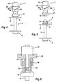
- Figures 1 to 3 show a first embodiment of the adapter 1 for the probe tube 2 of a PEG probe 3.
- the probe tube 2 of the PEG probe 3 has at its distal end a plate-shaped inner retaining member 4, with which the tube on the stomach inner wall supported.
- the outer retaining member 5, with which the PEG probe is supported on the abdominal wall, is part of the adapter.
- the retaining member 5 of the adapter is a circular disc of a cuddly, biocompatible material having a central opening 6 for passing the probe tube 2.
- the retaining member 5 On the side facing away from the patient, the retaining member 5 has a provided with an external thread 7 first sleeve-shaped clamping member 8, in the an elastic clamping ring 9 is inserted, through which the probe tube 2 is guided.
- a conical hollow pin 12 is concentrically arranged, on which the probe tube 2 is pushed.
- the first and second clamping part 8, 11 are screwed together, whereby the elastic clamping ring 9 exerts a radial clamping force on the tube.
- the housing body 43 of a obturator 13 connects, in which transverse to the longitudinal axis of the flow channel 14, a hollow cylindrical shut-off body 15 is rotatably mounted, which is open at one end 16, closed at the other end and provided with a central transverse bore 17 is.
- the cylinder body 15 can be rotated by means of a set screw 18, which is integral with the cylinder body.
- a positive Luer-lock connector 19 is attached to the housing body 43.
- a flexible tab 20 is attached laterally, to which a closure cap 21 is attached for closing the Luer-lock connector 19.
- the transfer hose of the transfer system has a negative luer lock connector.
- the protective cap 21 is removed from the positive Luer-lock connector 19 and the two luer-lock connectors of the adapter and the hose are connected together.
- Figures 4 to 6 show a second embodiment of the adapter, which differs from the embodiment according to Figures 1 to 3 by the obturator.
- the parts of the embodiment according to the figures 4 to 6, which correspond to the parts of the embodiment according to the figures 1 to 3, are provided with the same reference numerals.
- the adapter again has a retaining member 5 with a first sleeve-shaped clamping part 8 and a second sleeve-shaped clamping part 11auf.
- an elastic clamping ring 9 is again used to clamp the pushed onto the hollow pin 12 of the second clamping part probe tube 2 when screwing the two clamping parts.
- the second clamping member 11 is in this embodiment in a lower hollow cylindrical body 22, in which an upper hollow cylindrical body 23 is guided longitudinally displaceable.
- a cylindrical closure member 24 is arranged concentrically.
- the open end of the upper cylinder body 23 connects in the longitudinal direction of the flow channel 14, the positive Luer-lock connector 19 at.
- annular projection 25 is provided, from which a sleeve-shaped body 26 extends downwardly, which has a guide track 27 for extending from the lower cylinder body 22 radially outward guide pin 28.
- the upper part of the adapter 1 is rotated, so that the upper and lower cylinder body 22, 23 are pushed together and the cylindrical closure member 24 in the lumen of the upper cylinder body sealing introduced.
- its annular projection 25 may be provided with a knurling or the like.
- FIGS 7 to 9 show a third embodiment of the adapter, which differs from the embodiment according to the figures 4 to 6 by the retaining member 5 and the means for fixing the probe tube 2.
- the corresponding parts are again provided with the same reference numerals.
- the retaining member 27 is a plate-shaped element which is placed with its flat underside on the abdominal wall. It has an opening 30 for the passage of the probe tube. On its upper side define two parallel webs 31, 32 a subsequent to the opening 30 guide channel 33 for the hose 2.
- a unit 34 which is inserted into the retaining member 27 fits. The attachment of the hose to the adapter is not done by screwing two clamping parts, as in the embodiments of Figures 1 to 6.
- the adapter instead of the two clamping parts, the adapter according to the figures 7 to 9 at its hose end a profiled insert 35 with a conical hollow pin 36 for pushing on the hose.
- the insert 35 can be inserted into a correspondingly profiled recess 37 of the retaining member, which adjoins the guide channel.
- the profililiere recess 37 has a cylindrical portion 38 which receives the pushed onto the hollow pin piece of tubing by clamping.
- the probe tube 2 is guided for connection of the adapter through the opening 30, cut to the correct length and pushed onto the conical hollow pin 36 of the insert 35. Subsequently, the probe tube is bent by 90 ° and inserted into the guide channel 33, and the adapter is inserted with the insert 35 in the recess of the retaining member. there the hose piece sitting on the hollow pin is clamped. The guidance of the hose in the area of the deflection and in the attachment area reduces the risk of buckling. Moreover, the hose connection is relieved because the hose is clamped fixed. Further support provides the positive connection between the insert of the adapter and the profiled recess of the retaining member.
- profiled recess and a plurality of detent positions may be provided for inserting the insert to compensate for different lengths of the probe tube can.
- the areas of the retention member 27 with direct skin and tissue contact consist of a cuddly, biocompatible material, eg. As silicone rubber, whereas the remaining parts of the retaining member made of a harder materials, eg. B. thermoplastic materials are made.
- Fig. 10 shows another embodiment of the adapter, which differs from the embodiment according to the figures 7 to 9 characterized in that not the obturator according to the embodiments 4 to 6, but the obturator according to the figures 1 to 3 is used. Corresponding parts are again provided with the same reference numerals.
- the retaining member 27 again has an opening 30 for the probe tube 2 and a subsequent thereto guide channel 33, in which the tube is inserted.
- the profiled insert 35 of the adapter with the conical hollow pin 36 is inserted into the entprechend profiled recess 37 of the retaining member fitting, wherein the probe tube 2 is clamped in the cylindrical portion 38 of the recess on the hollow pin.
- the recess is formed such that the adapter with the adjusting screw 18 and the Luer-lock connector 19 is laterally supported on the Studchhalteglied 27.
- the fixing element 40 for the probe tube 2 during the installation of the PEG probe.
- the fixing element is formed as a flat plate, which is cut in the longitudinal direction.
- the incision 41 has a smaller width than the probe tube, so that the tube with the fixing element is clamped fixable.
- the thickness of the fixing element corresponds to the desired distance between the abdominal wall and the outer retaining member 5 of the adapter.
- the fixing element has a projecting lug 42.
- the fixation element is placed on the abdominal wall and pushed laterally onto the probe tube until the stop 42 abuts against the retaining member, so that the tube is fixed by clamping. Subsequently, the probe tube is cut off and the retaining member is fixed to the probe tube.
- the fixing element serves as a spacer.
Landscapes
- Health & Medical Sciences (AREA)
- Veterinary Medicine (AREA)
- Life Sciences & Earth Sciences (AREA)
- Animal Behavior & Ethology (AREA)
- General Health & Medical Sciences (AREA)
- Public Health (AREA)
- Pulmonology (AREA)
- Gastroenterology & Hepatology (AREA)
- Infusion, Injection, And Reservoir Apparatuses (AREA)
- Surgical Instruments (AREA)
- Medical Preparation Storing Or Oral Administration Devices (AREA)
- Ultra Sonic Daignosis Equipment (AREA)
- Measuring And Recording Apparatus For Diagnosis (AREA)
- Measurement Of The Respiration, Hearing Ability, Form, And Blood Characteristics Of Living Organisms (AREA)
- Medicines Containing Antibodies Or Antigens For Use As Internal Diagnostic Agents (AREA)
Description
- Die Erfindung betrifft einen Adapter zur nachträglichen Verkürzung einer PEG-Sonde, die zur künstlichen Ernährung bereits gelegt worden ist.
- Zum Legen einer PEG-Sonde wird ein Endoskop oder Gastroskop in den Magen des Patienten eingeführt, und der Magen wird durch Luftinsuflation entfaltet. Anschließend wird eine Kanüle durch die Bauchdecke und die Magenwand in das Magenlumen vorgeschoben. Durch die Kanüle wird ein Führungsfaden in das Magenlumen eingeführt, mit dem Endoskop oder Gastroskop erfaßt und durch Speiseröhre und Mund des Patienten wieder herausgezogen. Mit Hilfe des auf diese Weise gelegten Führungsfadens wird die Sonde dann bis zum Mageninneren und von dort über die Kanüle nach außen geführt. Dieser Eingriff wird auch als perkutane endoskopisch kontrollierte Gastrostomie (PEG) bezeichnet.
- Die bekannten PEG-Sonden, die allgemein Verwendung finden, weisen an ihrem distalen Ende ein inneres Rückhalteglied auf, mit dem sich der Sondenschlauch an der Mageninnenwandung abstützt. Der Sondenschlauch ist derart bemessen, daß er sich weit aus der Bauchdecke heraus erstreckt. An seinem proximalen Ende weist der Schlauch ein Anschlußteil auf, um das Überleitsystem zum Zuführen von Nährlösung konnektieren zu können. Zum Verschließen des Sondenschlauchs ist häufig noch eine konventionelle Schlauchklemme oder integrierte Verschlußkappe vorgesehen.
- In der Praxis haben sich die.bekannten PEG-Sonden bewährt Als störend wird aber vom aktiven Patienten der relativ weit vorstehende Sondenschlauch empfunden.
- Die US-A-5,549,657 beschreibt eine PEG-Sonde, die über einen Adapter zum Anschluß eines Überleitsystems verfügt. Der Adapter wird von einem Y-Schlitzventil verschlossen, das sich beim Konnektieren des Überleitsystems öffnet, Zum Öffnen des Ventils weist der Anschlußteil des Überleitsystems eine vorspringende Kanüle auf, die in den Adapter eingeführt wird. Nachteilig ist jedoch, daß die bekannte PEG-Sonde mit den konventionellen Oberleitsystemen, die einen Luer-Lock-Anschlußteil aufweisen, nicht direkt kompatibel ist. Darüber hinaus besteht die Gefahr, daß das Schlitzventil nicht vollständig abdichtet und zu schnell seine Funktionalität verliert.
- Die US 5,527,280 beschreibt eine Sonde zur enteralen Ernährung, die mehrere Lumen aufweist. Die Sonde verfügt über einen Adapter mit mehreren Anschlußstücken, die jeweils mit Stopfen verschließbar sind.
- Die DE 41 45 661 A1 offenbart eine Vorrichtung zur perkutanen enteralen Langzeitemährung. Der Strömungskanal auch dieser Sonde wird mit einem Stopfen verschlossen. Ein Absperrorgan mit dreh- oder verschiebbarem Verschlußkörper ist auch hier nicht vorgesehen. Die DE 690 16 263 T2 beschreibt eine Ernährungssonde, die wieder einen mit einem Stopfen verschließbaren Adapter aufweist.
- Eine PEG-Sonde mit einem Anschlussstück, das Bestandteil des Sondenschlauchs ist, beschreibt die US-A-5,836,924. Das Anschlussstück der PEG-Sonde weist einen drehbaren Verschlusskörper für den Strömungskanal auf.
- Der Erfindung liegt die Aufgabe zugrunde, einen universell einsetzbaren, einfach zu handhabenden und sicher zu verschließenden Adapter mit einer geringen Bauhöhe bereitzustellen, der die nachträgliche Verkürzung des Sondenschlauchs einer bereits gelegten PEG-Sonde erlaubt.
- Die Lösung dieser Aufgabe erfolgt erfindungsgemäß mit den Merkmalen des Patentanspruchs 1 und 10.
- Der erfindungsgemäße Adapter erlaubt die Verkürzung des Sondenschlauchs einer bereits gelegten PEG-Sonde, ohne die Notwendigkeit des Sondentauschs bei noch intaktem Katheterschlauch, wobei der Adapter an den nur ein kurzes Stück oberhalb der Bauchdecke abgeschnittenen Katheierschlauch angeschlossen wird.
- Zum Verschließen des Adapters ist ein Absperrorgan mit einem dreh- oder verschiebbaren Verschlußkörper vorgesehen. Das Absperrorgan ist insofern von Vorteil, als das Überleitsystem nicht über einen speziellen Anschlußteil zu verfügen braucht, der den Adapter beim Konnektieren öffnet. Daher können grundsätzlich alle Applikationssysteme der enteralen Ernährung (entsprechend der EN 1615) angeschlossen werden.
- Das sich an der Bauchdecke abstützende äußere Rückhalteglied des Adadpters sollte aus einem anschmiegsamen, elastischen Material, z. B. Silikonkautschuk mit besonders guten Biokompatibilitätseigenschaften bestehen, während die übrigen Teile des Adapters aus formstabilen Materialien, z. B. thermoplastischen Kunststoffen, gefertigt sein sollten, um dem Adapter die erforderliche Stabilität zu verleihen.
- Die Befestigung des Adapters an der PEG-Sonde erfolgt mit zwei hülsenförmigen Klemmteilen, die unter Verklemmung des proximalen Endes des fixierten Sondenschlauchs miteinander verschraubbar sind. Das erste hülsenförmige Klemmteil ist mit dem äußeren Rückhalteglied zwechmäßigerweise einstückig, kann aber auch in das Rückhalteglied lose eingesetzt sein.
- In das erste Klemmteil ist vorzugsweise ein elastischer Klemmring eingesetzt, während in dem zweiten Klemmteil ein konischer Hohlzapfen konzentrisch angeordnet ist. Vor dem Verschrauben der beiden Klemmteile wird der Sondenschlauch durch das erste Klemmteil geführt und auf den Hohlzapfen des zweiten Klemmteils geschoben. Beim Verschrauben des ersten und zweiten Klemmteils übt der Klemmring eine radiale Anpreßkraft auf den Schlauch aus, so daß dieser auf dem Hohlzapfen verklemmt wird. Damit kann eine ausreichende Zug- und Druckfestigkeit der Verbindung erreicht werden, ohne daß der Schlauch an der Klemmstelle beschädigt wird.
- Bei einer bevorzugten Ausführungsform weist der Adapter zum Anschluß des Überleitungsschlauchs einen Luer-Lock-Anschiußteil auf, der sich durch eine kleine Baugröße und eine sichere Konnexion auszeichnet.
- Der Verschlußkörper des Absperrorgans kann ein drehbar gelagerter Zylinderkörper sein, der an einem Ende verschlossen, an dem anderen Ende offen und mit einer Querbohrung versehen ist. Wenn der Verschlußkörper das Absperrorgan öffnet, kann Flüssigkeit aus dem Strömungskanal des Adapters durch die Querbohrung in den Zylinderkörper strömen. Dieser VerschluBkörper macht eine Anordnung des Luer-Lock-Anschlußteils quer zum Strömungskanal möglich, wodurch eine besonders geringe Bauhöhe des Adapters erreicht und ein seitlicher Anschluß des Überleitungsschlauchs möglich wird.
- Der Verschlvißkörper kann aber auch ein Verschlußstück sein, das in den Strömungskanal axial eingeschoben wird. Diese Ausführungsform ist von Vorteil, wenn der Luer-Lock-Anschlußteil in Längsrichtung des Strömungskanals angeordnet sein soll, d. h. der Überleitungsschlauch nicht seitlich angeschlossen wird.
- Zur Vereinfachung der Handhabung kann das Verschlußstück durch Drehen des äußeren Gehäusekörpers des Adapters verschoben werden. Die Umwandlung der rotatorischen Bewegung in eine translatorische Bewegung erfolgt dabei vorzugsweise mittels einer Führungsbahn.
- Da das Absperrorgan den Adapter dicht verschließt, kann auf eine zusätzliche Verschlußkappe prinzipiell verzichtet werden. Diese ist aber von Vorteil, als sie den Luer-Lock-Aschlußteil des Adapters schützt.
- Das Rückhalteglied ist vorzugsweise als scheibenförmiger Körper ausgebildet, so daß der Adapter eine möglichst geringe Bauhöhe hat.
- Bei einer alternativen Ausführungsform bilden die Befestigungsmittel, der Absperrkörper und die Anschlußmittel des Adapters eine Einheit, die passend in das Rückhalteglied einsetzbar ist. Dabei können je nach Schlauchlänge unterschiedliche Rastpositionen vorgesehen sein. Da das Rückhalteglied bei der Montage nicht im Wege steht, wird die Befestigung des Adapters an dem Sondenschlauch erleichtert.
- Zum Durchführen des Sondenschlauchs ist in dem Rückhalteglied ein Öffnung vorgesehen. Wenn der Sondenschlauch durch die Öffnung des Rückhalteglieds geführt und um 90° umgelenkt wird, kann ein besonders flaches Profil erzielt werden. Damit kann das Rückhalteglied ein kurzes Schlauchstück als Reserve aufnehmen, so daß der Schlauch nicht unmittelbar oberhalb der Bauchdecke abgeschnitten werden muß.
- Für den Schlauch ist in dem Rückhalteglied vorteilhaftetweise eine Führung vorgesehen, die den Schlauch fixiert und die Knickgefahr an der Biegestelle reduziert. Die Fixierung des Schlauchs kann aber auch allein dadurch erfolgen, daß die aus den Befestigungsmitteln, den Absperrkörper und die Anschlußmittel bestehende Einheit formschlüssig in dem Rückhalteglied sitzt.
- Im folgenden werden verschiedene Ausführungsbeispiele der Erfindung unter Bezugnahme auf die Zeichnungen näher erläutert.
-
- Fig. 1
- eine Seitenansicht einer ersten Ausführungsform des an eine PEG-Sonde angeschlossenen Adapters,
- Fig. 2
- den von der PEG-Sonde abgenommenen Adapter von Fig. 1,
- Fig. 3
- das Oberteil des Adapters von Fig. 2 in geschnittener Darstellung,
- Fig. 4
- ein zweites Ausführungsbeispiel des an der PEG-Sonde angeschlossenen Adapters,
- Fig. 5
- den von der PEG-Sonde abgenommenen Adapter von Fig. 4, und
- Fig. 6
- das Oberteil des Adapters von Fig. 4 in teilweise geschnittener Darstellung.
- Fig. 7
- eine dritte Ausführungsform des an die PEG-Sonde angeschlossenen Adapters in teilweise geschnittener Darstellung,
- Fig. 8
- eine Ansicht des Adapters aus der Richtung des Pfeils VIII von Fig. 7,
- Fig. 9
- einen Schnitt durch das Rückhalteglied des Adapters von Fig. 8 entlang der Linie IX - IX,
- Fig. 10
- eine weitere Ausführungsform des Adapters, und
- Fig. 11
- ein Fixierungselement für den Sondenschlauch.
- Die Figuren 1 bis 3 zeigen eine erste Ausführungsform des Adapters 1 für den Sondenschlauch 2 einer PEG-Sonde 3. Der Sondenschlauch 2 der PEG-Sonde 3 weist an seinem distalen Ende ein plattenförmiges inneres Rückhalteglied 4 auf, mit dem sich der Schlauch an der Mageninnenwandung abstützt. Das äußere Rückhalteglied 5, mit dem sich die PEG-Sonde an der Bauchdecke abstützt, ist Bestandteil des Adapters.
- Das Rückhalteglied 5 des Adapters ist eine kreisförmige Scheibe aus einem anschmiegsamen, biokompatiblen Material mit einer zentralen Öffnung 6 zum Durchführen des Sondenschlauchs 2. An der dem Patienten abgewandten Oberseite weist das Rückhalteglied 5 ein mit einem Außengewinde 7 versehenes erstes hülsenförmiges Klemmteil 8 auf, in das ein elastischer Klemmring 9 eingesetzt ist, durch den der Sondenschlauch 2 geführt wird. In einem mit einem entsprechenden Innengewinde 10 versehenen zweiten hülsenförmigen Klemmteil 11 ist ein konischer Hohlzapfen 12 konzentrisch angeordnet, auf den der Sondenschlauch 2 aufgeschoben wird. Zum Verklemmen des Sondenschlauchs werden das erste und zweite Klemmteil 8, 11 miteinander verschraubt, wodurch der elastische Klemmring 9 eine radiale Klemmkraft auf den Schlauch ausübt.
- An das zweite Klemmteil 11 schließt sich der Gehäusekörper 43 eines Absperrorgans 13 an, in dem quer zur Längsachse des Strömungskanals 14 ein hohlzylindrischer Absperrkörper 15 drehbar gelagert ist, der an einem Ende 16 offen, an dem anderen Ende geschlossen und mit einer zentralen Querbohrung 17 versehen ist. Der Zylinderkörper 15 kann mittels einer Stellschraube 18 gedreht werden, die mit dem Zylinderkörper einstückig ist. Vor dem offenen Ende 16 des Zylinderkörpers ist an den Gehäusekörper 43 ein positiver Luer-Lock-Anschlußteil 19 angesetzt. An dem Gehäusekörper 43 ist seitlich eine flexible Lasche 20 befestigt, an der eine Verschlußkappe 21 zum Verschließen des Luer-Lock-Anschlußteils 19 angebracht ist.
- Zum Verkürzen des Sondenschlauchs 2 der bereits verlegten PEG-Sonde 3 wird der Schlauch oberhalb der Bauchdecke gerade abgeschnitten, das vorstehende Schlauchende durch das Rückhalteglied 5 mit dem ersten Klemmstück 8 geführt und auf den Hohlzapfen 12 des zweiten Klemmstücks 11 aufgeschoben. Anschließend werden beide Klemmstücke miteinander verschraubt.
- Der nicht dargestellte Überleitungsschlauch des Überleitsystems verfügt über eine negativen Luer-Lock-Anschlußteil. Zum Anschluß des Überleitungsschlauchs wird die Schutzkappe 21 von dem positiven Luer-Lock-Anschlußteil 19 abgenommen und die beiden Luer-Lock-Anschlußteile des Adapter und des Schlauchs werden miteinander verbunden.
- Die Figuren 4 bis 6 zeigen ein zweites Ausführungsbeispiel des Adapters, der sich von der Ausführungsform gemäß der Figuren 1 bis 3 durch das Absperrorgan unterscheidet. Die Teile des Ausführungsbeispiels gemäß der Figuren 4 bis 6, die den Teilen der Ausführungsform gemäß der Figuren 1 bis 3 entsprechen, sind mit den gleichen Bezugszeichen versehen.
- Der Adapter weist wieder ein Rückhalteglied 5 mit einem ersten hülsenförmigen Klemmteil 8 und einem zweiten hülsenförmigen Klemmteil 11auf. In das erste Klemmteil 8 ist wieder ein elastischer Klemmring 9 eingesetzt, um beim Zusammenschrauben der beiden Klemmteile den auf den Hohlzapfen 12 des zweiten Klemmteils aufgeschobenen Sondenschlauch 2 zu verklemmen.
- Das zweite Klemmteil 11 geht bei dieser Ausführungsform in einen unteren hohlzylindrischen Körper 22 über, in dem ein oberer hohlzylindrischer Körper 23 längsverschiebbar geführt ist. In dem unterer Zylinderkörper 22 ist ein zylindrisches Verschlußstück 24 konzentrisch angeordnet. An das offene Ende des oberen Zylinderkörpers 23 schließt sich in Längsrichtung des Strömungskanals 14 das positive Luer-Lock-Anschlußteil 19 an.
- An der Unterseite des Luer-Lock-Anschlußteils 19 ist ein ringförmiger Ansatz 25 vorgesehen, von dem sich nach unten ein hülsenförmiger Körper 26 erstreckt, der eine Führungsbahn 27 für einen sich von dem unteren Zylinderkörper 22 radial nach außen streckenden Führungsstift 28 aufweist.
- Zum Verschließen der PEG-Sonde 3 wird der obere Teil des Adapters 1 verdreht, so daß der obere und untere Zylinderkörper 22, 23 zusammengeschoben werden und das zylindrische Verschlußstück 24 in das Lumen des oberen Zylinderkörpers dichtend eingeführt wird. Um den Adapter besser greifen zu können, kann dessen ringförmiger Ansatz 25 mit einer Rändelung oder dgl. versehen sein.
- Die Figuren 7 bis 9 zeigen eine dritte Ausführungsform des Adapters, die sich von dem Ausführungsbeispiel gemäß der Figuren 4 bis 6 durch das Rückhalteglied 5 und die Mittel zur Befestigung des Sondenschlauchs 2 unterscheidet. Die einander entsprechenden Teile sind wieder mit den gleichen Bezugszeichen versehen.
- Das Rückhalteglied 27 ist ein plattenförmiges Element, das mit seiner flachen Unterseite auf die Bauchdecke aufgelegt wird. Es weist eine Öffnung 30 zum Durchführen des Sondenschlauchs auf. An seiner Oberseite begrenzen zwei parallel verlaufende Stege 31, 32 einen sich an die Öffnung 30 anschließenden Führungskanal 33 für den Schlauch 2. Bei der Ausführungsform gemäß der Figuren 7 bis 9 bilden die Mittel zur Befestigung des Sondenschlauchs, das Absperrorgan und die Mittel zum Anschluß des Überleitungsschlauchs eine Einheit 34, die in das Rückhalteglied 27 passend eingesetzt wird. Die Befestigung des Schlauchs an dem Adapter erfolgt nicht durch Verschrauben zweier Klemmteile, wie bei den Ausführungsbeispielen gemäß der Figuren 1 bis 6. Anstelle der beiden Klemmteile weist der Adapter gemäß der Figuren 7 bis 9 an seinem schlauchseitigen Ende ein profiliertes Einsatzstück 35 mit einem konischen Hohlzapfen 36 zum Aufschieben des Schlauchs auf. Das Einsatzstück 35 kann in eine entsprechend profilierte Ausnehmung 37 des Rückhaltegliedes eingesetzt werden, die sich an den Führungskanal anschließt. Die profililierte Ausnehmung 37 weist einen zylindrischen Abschnitt 38 auf, der das auf den Hohlzapfen aufgeschobene Schlauchstück klemmend aufnimmt.
- Der Sondenschlauch 2 wird zum Anschluß des Adapters durch die Öffnung 30 geführt, auf die richtige Länge abgeschnitten und auf den konischen Hohlzapfen 36 des Einsatzstücks 35 aufgeschoben. Anschließend wird der Sondenschlauch um 90° gebogen und in den Führungskanal 33 eingelegt, und der Adapter wird mit dem Einsatzstück 35 in die Ausnehmung des Rückhaltegliedes eingesetzt. Dabei wird das auf dem Hohlzapfen sitzende Schlauchstück klemmend fixiert. Die Führung des Schlauchs im Bereich der Umlenkung und im Befestigungsbereich reduziert die Knickgefahr. Im übrigen wird die Schlauchverbindung entlastet, da der Schlauch klemmend fixiert ist. Weiteren Rückhalt bietet die formschlüssige Verbindung zwischen dem Einsatzstück des Adapters und der profilierten Ausnehmung des Rückhalteglieds.
- In der profilierten Ausnehmung können auch mehrere Rastpositionen zum Einsetzen des Einsatzstücks vorgesehen sein, um unterschiedliche Längen des Sondenschlauchs ausgleichen zu können.
- Die Bereiche des Rückhalteglieds 27 mit direktem Haut- und Gewebekontakt bestehen aus einem anschmiegsamen, biokompatiblen Werkstoff, z. B. Silikonlcautschuk, wohingegen die übrigen Teile des Rückhalteglieds aus einem härteren Materialien, z. B. thermoplastischen Kunststoffen gefertigt sind.
- Fig. 10 zeigt ein weiteres Ausführungsbeispiel des Adapters, das sich von der Ausführungsform gemäß der Figuren 7 bis 9 dadurch unterscheidet, daß nicht das Absperrorgan gemäß der Ausführungsformen 4 bis 6, sondern das Absperrorgan gemäß der Figuren 1 bis 3 Verwendung findet. Einander entsprechende Teile sind wieder mit gleichen Bezugszeichen versehen.
- Das Rückhalteglied 27 weist wieder eine Öffnung 30 für den Sondenschlauch 2 und einen sich daran sich anschließenden Führungskanal 33 auf, in den der Schlauch eingelegt wird. Das profilierte Einsatzstück 35 des Adapters mit dem konischen Hohlzapfen 36 wird in die entprechend profilierte Ausnehmung 37 des Rückhalteglieds passend eingesetzt, wobei der Sondenschlauch 2 in dem zylindrischen Abschnitt 38 der Ausnehmung auf dem Hohlzapfen verklemmt wird. Die Ausnehmung ist derart ausgebildet, daß sich der Adapter mit der Stellschraube 18 und dem Luer-Lock-Anschlußteil 19 an dem Rüchhalteglied 27 seitlich abstützt.
- Fig. 11 zeigt ein Fixierungselement 40 für den Sondenschlauch 2 bei der Anlage der PEG-Sonde. Das Fixierungselement ist als flaches Plättchen ausgebildet, das in Längsrichtung eingeschnitten ist. Der Einschnitt 41 hat eine geringere Breite als der Sondenschlauch, so daß der Schlauch mit dem Fixierungselement klemmend fixierbar ist. Die Dicke des Fixierungselements entspricht dem gewünschten Abstand zwischen Bauchdecke und äußerem Rückhalteglied 5 des Adapters. An dem Rand, der dem Einschnitt gegenüberliegt, weist das Fixierungselement einen vorspringenden Ansatz 42 auf. Zur Anlage der PEG-Sonde wird das Fixierungselement auf die Bauchdecke aufgelegt und seitlich auf den Sondenschlauch geschoben, bis der Anschlag 42 an dem Rückhalteglied anschlägt, so daß der Schlauch klemmend fixiert ist. Anschließend wird der Sondenschlauch abgeschnitten, und das Rückhalteglied wird an dem Sondenschlauch fixiert. Dabei dient das Fixierungselement als Abstandshalter.
Claims (13)
- Adapter für eine PEG-Sonde mit einem sich an der Mageninnenwandung abstützenden inneren Rückhalteglied an ihrem distalen Ende und einem offenen proximalen Ende, wobei der Adapter aufweist:einen Strömungskanal (14), ein sich an der Bauchdecke abstützendes äußeres Rückhalteglied (5), Mittel (15,24) zum Verschließen des Strömungskanals und Mittel (19) zum Anschluß eines Überleitungsschlauchs an den Strömungskanal, wobei das Mittel zum Verschließen des Strömungskanals ein Absperrorgan ist, das mit einem drehbaren oder verschiebbaren Verschlußkörper (15,24) verschließbar ist, dadurch gekennzeichet, daß der Adapter ferner Mittel (8,11) zur Befestigung des proximalen Endes der PEG-Sonde an dem Rückhalteglied aufweist, und das Mittel zur Befestigung der PEG-Sonde ein erstes hülsenförmiges Klemmteil (8), das mit dem äußeren Rückhalteglied (5) einstückig ist, und ein zweites hülsenförmiges Klemmteil (11) aufweist, wobei das erste und zweite Klemmteil unter Verklemmung der PEG-Sonde miteinander verschraubbar sind.
- Adapter nach Anspruch 1, dadurch gekennzeichnet, daß das Mittel zum Anschluß des Überleitungsschlauchs ein Luer-Lock-Anschlußteil (19) ist.
- Adapter nach Anspruch 2, dadurch gekennzeichnet, daß der Luer-Lock-Anschlußteil (19) mit einer Verschlußkappe (21) verschließbar ist.
- Adapter nach Anspruch 3, dadurch gekennzeichnet, daß in das erste hülsenförmige Klemmteil (8) ein elastischer Klemmring (9) eingesetzt ist und in dem zweiten hülsenförmigen Klemmteil (11) ein konischer Hohlzapfen (12) konzentrisch angeordnet ist.
- Adapter nach einem der Anspruche 1 bis 4, dadurch gekennzeichnet, daß der Verschlußkörper ein um eine Achse quer zum Strömungskanal (14) drehbar gelagerter Zylinderkörper (15) ist, der an einem Ende verschlossen, an dem anderen Ende (16) offen und mit einer Querbohrung (17) versehen ist, wobei das Mittel (19) zur Befestigung der PEG-Sonde an dem offenen Ende des Verschlußkörpers angeordnet ist.
- Adapter nach einem der Ansprüche 1 bis 5, dadurch gekennzeichnet, daß der Verschlußkörper ein zylindrisches Verschlußstück (24) ist, das in den Strömungskanal (14) axial einschiebbar ist.
- Adapter nach Anspruch 6, dadurch gekennzeichnet, daß das zylindrische Verschlußstück (24) in einem ersten Zylinderkörper (22) konzentrisch angeordnet ist, der mit dem Rückhalteglied (5) einstückig ist, und in den ersten Zylinderkörper ein zweiter Zylinderkörper (23) eingesetzt ist, wobei der erste und zweite Zylinderkörper mittels einer Führung (28,29) gegeneinander verschiebbar sind.
- Adapter nach Anspruch 7, dadurch gekennzeichnet, daß der Luer-Lock-Anschlul3teil (19) an dem zweiten Zylinderkörper (23) in Längsrichtung des Strömungskanals (14) angeordnet ist.
- Adapter nach einem der Ansprüche 1 bis 8, dadurch gekennzeichnet, daß das Rückhalteglied (5) als scheibenförmiger Körper ausgebildet ist.
- Adapter für eine PEG-Sonde mit einem sich an der Mageninnenwandung abstützenden inneren Rückhalteglied an ihrem distalen Ende und einem offenen proximalen Ende, wobei der Adapter aufweist:einen Strömungskanal (14), ein sich an der Bauchdecke abstützendes äußeres Rückhalteglied (5), Mittel (15,24) zum Verschließen des Strömungskanals und Mittel (19) zum Anschluß eines Überleitungsschlauchs an den Strömungskanal, wobei das Mittel zum Verschließen des Strömungskanals ein Absperrorgan ist, das mit einem drehbaren oder verschiebbaren Verschlußkörper (15,24) verschließbar ist , dadurch gekennzeichnet, daß der Adapter ferner Mittel (8,11) zur Befestigung des proximalen Endes der PEG-Sonde an dem Rückhalteglied aufweist, und das Rückhalteglied (27) eine Öffnung (30) zum Durchführen der PEG-Sonde und eine Ausnehmung (37) aufweist, wobei die Mittel zur Befestigung des proximalen Endes der PEG-Sonde, das Absperrorgan und die Mittel zum Anschluß des Überleitungsschlauchs eine Einheit (34) bilden, die in die Ausnehmung einsetzbar ist.
- Adapter nach Anspruch 10, dadurch gekennzeichnet, daß die Ausnehmung (37) einen zylindrischen Klemmabschnitt (38) aufweist.
- Adapter nach Anspruch 11, dadurch gekennzeichnet, daß das Rückhalteglied (27) einen Führungskanal (33) aufweist, der sich an die Öffnung (30) anschließt.
- Adapter nach einem der Ansprüche 1 bis 12, gekennzeichnet durch ein Fixierungselement (40) zur klemmenden Fixierung des Sondenschlauchs, das als flaches Plättchen mit einem seitlichen Einschnitt (41) ausgebildet ist.
Applications Claiming Priority (3)
| Application Number | Priority Date | Filing Date | Title |
|---|---|---|---|
| DE10055283A DE10055283B4 (de) | 2000-11-08 | 2000-11-08 | Adapter für eine PEG-Sonde |
| DE10055283 | 2000-11-08 | ||
| PCT/EP2001/012753 WO2002038102A1 (de) | 2000-11-08 | 2001-11-03 | Adapter für eine peg-sonde |
Publications (2)
| Publication Number | Publication Date |
|---|---|
| EP1331912A1 EP1331912A1 (de) | 2003-08-06 |
| EP1331912B1 true EP1331912B1 (de) | 2007-03-07 |
Family
ID=7662527
Family Applications (1)
| Application Number | Title | Priority Date | Filing Date |
|---|---|---|---|
| EP01993444A Expired - Lifetime EP1331912B1 (de) | 2000-11-08 | 2001-11-03 | Adapter für eine peg-sonde |
Country Status (9)
| Country | Link |
|---|---|
| US (1) | US7063690B2 (de) |
| EP (1) | EP1331912B1 (de) |
| JP (1) | JP4180915B2 (de) |
| AT (1) | ATE355814T1 (de) |
| AU (1) | AU2002216006A1 (de) |
| CA (1) | CA2428148C (de) |
| DE (2) | DE10055283B4 (de) |
| ES (1) | ES2278812T3 (de) |
| WO (1) | WO2002038102A1 (de) |
Families Citing this family (14)
| Publication number | Priority date | Publication date | Assignee | Title |
|---|---|---|---|---|
| DE102004005372A1 (de) | 2004-02-03 | 2005-08-18 | Fresenius Medical Care Deutschland Gmbh | Vorrichtung und Verfahren zum Einbringen eines Verschlußstopfens in einen Patientenkonnektor für die Peritonealdialyse |
| JP2005330205A (ja) * | 2004-05-19 | 2005-12-02 | Mitsubishi Chemicals Corp | (メタ)アクロレイン又は(メタ)アクリル酸の製造方法 |
| US7896859B2 (en) | 2005-10-20 | 2011-03-01 | Tyco Healthcare Group Lp | Enteral feeding set |
| US7611502B2 (en) | 2005-10-20 | 2009-11-03 | Covidien Ag | Connector for enteral fluid delivery set |
| US8221363B2 (en) | 2006-10-18 | 2012-07-17 | Baxter Healthcare S.A. | Luer activated device with valve element under tension |
| US7981090B2 (en) | 2006-10-18 | 2011-07-19 | Baxter International Inc. | Luer activated device |
| US7753338B2 (en) | 2006-10-23 | 2010-07-13 | Baxter International Inc. | Luer activated device with minimal fluid displacement |
| US8366697B2 (en) * | 2008-02-08 | 2013-02-05 | Codan Us Corporation | Enteral feeding safety reservoir and system |
| US8864736B2 (en) * | 2008-02-08 | 2014-10-21 | Codan Us Corporation | Enteral feeding safety reservoir and system |
| US7955317B2 (en) | 2009-06-30 | 2011-06-07 | Tyco Healthcare Group Lp | Female adaptor for feeding line |
| DE102010019691A1 (de) * | 2010-05-07 | 2011-11-10 | Sartorius Stedim Biotech Gmbh | Ventil für einen Behälter |
| EP2497525B1 (de) * | 2011-03-09 | 2014-06-04 | Covidien LP | Verbindungselement zum Verbinden einer Spritze an ein Gastrostomierohr |
| DE102012004673A1 (de) * | 2012-03-12 | 2013-09-12 | Fresenius Medical Care Deutschland Gmbh | Schlauchadapter zum Beeinflussen des Drucks innerhalb eines Schlauchabschnitts während einer medizinischen Behandlung |
| US20230105889A1 (en) * | 2021-09-22 | 2023-04-06 | Micro-Tech Endoscopy USA, Inc. | Irrigation catheter with optional enteral feeding functionality or stomach-in fluid aspiration functionality |
Family Cites Families (16)
| Publication number | Priority date | Publication date | Assignee | Title |
|---|---|---|---|---|
| US4393873A (en) * | 1980-03-10 | 1983-07-19 | Nawash Michael S | Gastrostomy and other percutaneous transport tubes |
| US4315513A (en) * | 1980-03-10 | 1982-02-16 | Nawash Michael S | Gastrostomy and other percutaneous transport tubes |
| FR2581315A1 (fr) * | 1985-05-03 | 1986-11-07 | Biomasys Sa | Tete amovible de raccordement a un dispositif inamovible de passage percutane pour acces a un circuit de fluides dans un organisme vivant, boitier de distribution de fluides et systeme comportant cette tete de raccordement et ce boitier de distribution de fluides |
| US5197634A (en) * | 1989-05-09 | 1993-03-30 | Creative Packaging Corp. | Side orifice dispensing closure |
| US5071405A (en) * | 1989-06-02 | 1991-12-10 | Abbott Laboratories | Gastrostomy tube |
| US5125897A (en) * | 1990-04-27 | 1992-06-30 | Corpak, Inc. | Gastrostomy device with one-way valve and cuff pin |
| US5374254A (en) * | 1990-11-29 | 1994-12-20 | Buma; Shelley J. | Catheters with adjustable external locking bolsters |
| US5267969A (en) * | 1992-10-08 | 1993-12-07 | Abbott Laboratories | External retaining device for feeding tube or the like |
| US5549657A (en) | 1994-05-12 | 1996-08-27 | C.R. Bard, Inc. | Low profile adaptor for gastrostomy feeding tube |
| US5527280A (en) * | 1995-03-29 | 1996-06-18 | The Children's Seashore House | Multi-lumen enteral feeding and medicating device |
| DE19543011C2 (de) * | 1995-11-17 | 1998-11-12 | Stefan Dr Med Benz | Vorrichtung zur transabdominellen intraluminalen Manipulation in Hohlorganen |
| US6019746A (en) * | 1996-05-17 | 2000-02-01 | Applied Medical Technology, Inc. | Low profile balloon feeding device |
| DE19634116C2 (de) * | 1996-08-23 | 1998-08-20 | Fresenius Ag | Katheter für die perkutane enterale Ernährung |
| US5836924A (en) * | 1997-01-02 | 1998-11-17 | Mri Manufacturing And Research, Inc. | Feeding tube apparatus with rotational on/off valve |
| US6328720B1 (en) * | 2000-02-18 | 2001-12-11 | Zevex, Inc. | Low-profile enterostomy device |
| DE10139644B4 (de) * | 2001-08-11 | 2004-04-01 | Fresenius Kabi Deutschland Gmbh | Montageteil für einen Adapter einer PEG-Sonde und Adapter für eine PEG-Sonde mit einem derartigen Montageteil |
-
2000
- 2000-11-08 DE DE10055283A patent/DE10055283B4/de not_active Expired - Fee Related
-
2001
- 2001-11-03 ES ES01993444T patent/ES2278812T3/es not_active Expired - Lifetime
- 2001-11-03 WO PCT/EP2001/012753 patent/WO2002038102A1/de not_active Ceased
- 2001-11-03 AT AT01993444T patent/ATE355814T1/de active
- 2001-11-03 AU AU2002216006A patent/AU2002216006A1/en not_active Abandoned
- 2001-11-03 DE DE50112168T patent/DE50112168D1/de not_active Expired - Lifetime
- 2001-11-03 EP EP01993444A patent/EP1331912B1/de not_active Expired - Lifetime
- 2001-11-03 JP JP2002540692A patent/JP4180915B2/ja not_active Expired - Fee Related
- 2001-11-03 CA CA2428148A patent/CA2428148C/en not_active Expired - Fee Related
-
2003
- 2003-05-07 US US10/431,034 patent/US7063690B2/en not_active Expired - Fee Related
Also Published As
| Publication number | Publication date |
|---|---|
| DE10055283A1 (de) | 2002-06-06 |
| DE10055283B4 (de) | 2004-07-15 |
| JP4180915B2 (ja) | 2008-11-12 |
| AU2002216006A1 (en) | 2002-05-21 |
| JP2004512902A (ja) | 2004-04-30 |
| WO2002038102A1 (de) | 2002-05-16 |
| CA2428148A1 (en) | 2002-05-16 |
| US20030216712A1 (en) | 2003-11-20 |
| EP1331912A1 (de) | 2003-08-06 |
| ATE355814T1 (de) | 2007-03-15 |
| DE50112168D1 (de) | 2007-04-19 |
| CA2428148C (en) | 2010-04-06 |
| ES2278812T3 (es) | 2007-08-16 |
| US7063690B2 (en) | 2006-06-20 |
Similar Documents
| Publication | Publication Date | Title |
|---|---|---|
| DE60215737T2 (de) | Schutzhüllenanordnung mit einer Schutzhülle, einem Dilatator und einer Haltevorrichtung | |
| DE69631045T2 (de) | Gastrostomie-Ernährungsanschlüsse mit einwandfrei abdichtenden Eintrittsventilen | |
| DE3210148C2 (de) | Konnektor | |
| DE69124164T2 (de) | Implantierbare infusionsvorrichtung | |
| DE69123748T2 (de) | Katheteranschlussvorrichtung mit geteiltem zylinder | |
| DE69828281T2 (de) | Subkutaninfusionsvorrichtung | |
| EP2416837B1 (de) | Verbindungsstück für den sondenschlauch einer enteralen ernährungssonde und anordnung aus einer enteralen ernährungssonde und einem enteralen überleitsystem | |
| DE10055283B4 (de) | Adapter für eine PEG-Sonde | |
| EP1331962B1 (de) | Adapter für eine peg-sonde | |
| DE10149051B4 (de) | Vorrichtung zur Katheterkonnektion aus Träger, Hülse und Verbindungsstruktur | |
| CH691726A5 (de) | Konnektierungssystem für medizinische Anwendungen. | |
| CH702371A1 (de) | Verankerungsvorrichtung für Leitung in einem Schädel-Bohrloch. | |
| EP1083834B1 (de) | Vorrichtung zum schaffen eines transkutanen zuganges zu einem körperinneren hohlorgan | |
| DE102007025900A1 (de) | Verschlußvorrichtung für Venenverweilkanülen | |
| DE10139644B4 (de) | Montageteil für einen Adapter einer PEG-Sonde und Adapter für eine PEG-Sonde mit einem derartigen Montageteil | |
| EP0204986B1 (de) | Nasenolive | |
| EP0824929A2 (de) | Katheter für die perkutane enterale Ernährung | |
| DE3050812C2 (de) | Katheterisierungsvorrichtung | |
| DE3140192A1 (de) | Katheter | |
| WO1998053874A1 (de) | Kathetereinführvorrichtung mit einer einrichtung zum flüssigkeitsdichten abklemmen des einführungslumens | |
| DE10051593C2 (de) | PEG-Sonden-Adapter | |
| DE3444909A1 (de) | Katheter fuer die enterale ernaehrung zur insbesondere intraduodenalen applikation mittels einer gastrostomie | |
| DE19650664C1 (de) | Medizinische Vorrichtung zum Zuführen von Flüssigkeiten | |
| EP0761198A1 (de) | Katheter für die perkutane enterale Ernährung | |
| WO2003041601A1 (de) | Vorrichtung zur verbindung eines längsträgers mit einem knochenfixationsmittel |
Legal Events
| Date | Code | Title | Description |
|---|---|---|---|
| PUAI | Public reference made under article 153(3) epc to a published international application that has entered the european phase |
Free format text: ORIGINAL CODE: 0009012 |
|
| 17P | Request for examination filed |
Effective date: 20030426 |
|
| AK | Designated contracting states |
Designated state(s): AT BE CH CY DE DK ES FI FR GB GR IE IT LI LU MC NL PT SE TR |
|
| AX | Request for extension of the european patent |
Extension state: AL LT LV MK RO SI |
|
| GRAP | Despatch of communication of intention to grant a patent |
Free format text: ORIGINAL CODE: EPIDOSNIGR1 |
|
| GRAS | Grant fee paid |
Free format text: ORIGINAL CODE: EPIDOSNIGR3 |
|
| GRAA | (expected) grant |
Free format text: ORIGINAL CODE: 0009210 |
|
| AK | Designated contracting states |
Kind code of ref document: B1 Designated state(s): AT BE CH CY DE DK ES FI FR GB GR IE IT LI LU MC NL PT SE TR |
|
| PG25 | Lapsed in a contracting state [announced via postgrant information from national office to epo] |
Ref country code: FI Free format text: LAPSE BECAUSE OF FAILURE TO SUBMIT A TRANSLATION OF THE DESCRIPTION OR TO PAY THE FEE WITHIN THE PRESCRIBED TIME-LIMIT Effective date: 20070307 |
|
| REG | Reference to a national code |
Ref country code: GB Ref legal event code: FG4D Free format text: NOT ENGLISH |
|
| REG | Reference to a national code |
Ref country code: CH Ref legal event code: EP |
|
| REF | Corresponds to: |
Ref document number: 50112168 Country of ref document: DE Date of ref document: 20070419 Kind code of ref document: P |
|
| GBT | Gb: translation of ep patent filed (gb section 77(6)(a)/1977) |
Effective date: 20070329 |
|
| REG | Reference to a national code |
Ref country code: IE Ref legal event code: FG4D Free format text: LANGUAGE OF EP DOCUMENT: GERMAN |
|
| REG | Reference to a national code |
Ref country code: SE Ref legal event code: TRGR |
|
| PG25 | Lapsed in a contracting state [announced via postgrant information from national office to epo] |
Ref country code: PT Free format text: LAPSE BECAUSE OF FAILURE TO SUBMIT A TRANSLATION OF THE DESCRIPTION OR TO PAY THE FEE WITHIN THE PRESCRIBED TIME-LIMIT Effective date: 20070807 |
|
| REG | Reference to a national code |
Ref country code: ES Ref legal event code: FG2A Ref document number: 2278812 Country of ref document: ES Kind code of ref document: T3 |
|
| ET | Fr: translation filed | ||
| REG | Reference to a national code |
Ref country code: IE Ref legal event code: FD4D |
|
| PLBE | No opposition filed within time limit |
Free format text: ORIGINAL CODE: 0009261 |
|
| STAA | Information on the status of an ep patent application or granted ep patent |
Free format text: STATUS: NO OPPOSITION FILED WITHIN TIME LIMIT |
|
| PG25 | Lapsed in a contracting state [announced via postgrant information from national office to epo] |
Ref country code: IE Free format text: LAPSE BECAUSE OF FAILURE TO SUBMIT A TRANSLATION OF THE DESCRIPTION OR TO PAY THE FEE WITHIN THE PRESCRIBED TIME-LIMIT Effective date: 20070307 Ref country code: DK Free format text: LAPSE BECAUSE OF FAILURE TO SUBMIT A TRANSLATION OF THE DESCRIPTION OR TO PAY THE FEE WITHIN THE PRESCRIBED TIME-LIMIT Effective date: 20070307 |
|
| 26N | No opposition filed |
Effective date: 20071210 |
|
| PG25 | Lapsed in a contracting state [announced via postgrant information from national office to epo] |
Ref country code: GR Free format text: LAPSE BECAUSE OF FAILURE TO SUBMIT A TRANSLATION OF THE DESCRIPTION OR TO PAY THE FEE WITHIN THE PRESCRIBED TIME-LIMIT Effective date: 20070608 |
|
| PG25 | Lapsed in a contracting state [announced via postgrant information from national office to epo] |
Ref country code: MC Free format text: LAPSE BECAUSE OF NON-PAYMENT OF DUE FEES Effective date: 20071130 |
|
| PG25 | Lapsed in a contracting state [announced via postgrant information from national office to epo] |
Ref country code: CY Free format text: LAPSE BECAUSE OF FAILURE TO SUBMIT A TRANSLATION OF THE DESCRIPTION OR TO PAY THE FEE WITHIN THE PRESCRIBED TIME-LIMIT Effective date: 20070307 |
|
| PG25 | Lapsed in a contracting state [announced via postgrant information from national office to epo] |
Ref country code: LU Free format text: LAPSE BECAUSE OF NON-PAYMENT OF DUE FEES Effective date: 20071103 |
|
| REG | Reference to a national code |
Ref country code: DE Ref legal event code: R082 Ref document number: 50112168 Country of ref document: DE |
|
| PGFP | Annual fee paid to national office [announced via postgrant information from national office to epo] |
Ref country code: FR Payment date: 20141118 Year of fee payment: 14 Ref country code: GB Payment date: 20141127 Year of fee payment: 14 Ref country code: SE Payment date: 20141128 Year of fee payment: 14 Ref country code: ES Payment date: 20141126 Year of fee payment: 14 Ref country code: DE Payment date: 20141128 Year of fee payment: 14 Ref country code: TR Payment date: 20141021 Year of fee payment: 14 Ref country code: CH Payment date: 20141127 Year of fee payment: 14 |
|
| PGFP | Annual fee paid to national office [announced via postgrant information from national office to epo] |
Ref country code: NL Payment date: 20141126 Year of fee payment: 14 Ref country code: AT Payment date: 20141021 Year of fee payment: 14 |
|
| PGFP | Annual fee paid to national office [announced via postgrant information from national office to epo] |
Ref country code: IT Payment date: 20141127 Year of fee payment: 14 |
|
| PGFP | Annual fee paid to national office [announced via postgrant information from national office to epo] |
Ref country code: BE Payment date: 20141128 Year of fee payment: 14 |
|
| REG | Reference to a national code |
Ref country code: DE Ref legal event code: R119 Ref document number: 50112168 Country of ref document: DE |
|
| REG | Reference to a national code |
Ref country code: CH Ref legal event code: PL |
|
| REG | Reference to a national code |
Ref country code: AT Ref legal event code: MM01 Ref document number: 355814 Country of ref document: AT Kind code of ref document: T Effective date: 20151103 |
|
| GBPC | Gb: european patent ceased through non-payment of renewal fee |
Effective date: 20151103 |
|
| PG25 | Lapsed in a contracting state [announced via postgrant information from national office to epo] |
Ref country code: CH Free format text: LAPSE BECAUSE OF NON-PAYMENT OF DUE FEES Effective date: 20151130 Ref country code: LI Free format text: LAPSE BECAUSE OF NON-PAYMENT OF DUE FEES Effective date: 20151130 Ref country code: IT Free format text: LAPSE BECAUSE OF NON-PAYMENT OF DUE FEES Effective date: 20151103 |
|
| REG | Reference to a national code |
Ref country code: NL Ref legal event code: MM Effective date: 20151201 |
|
| REG | Reference to a national code |
Ref country code: FR Ref legal event code: ST Effective date: 20160729 |
|
| PG25 | Lapsed in a contracting state [announced via postgrant information from national office to epo] |
Ref country code: SE Free format text: LAPSE BECAUSE OF NON-PAYMENT OF DUE FEES Effective date: 20151104 Ref country code: AT Free format text: LAPSE BECAUSE OF NON-PAYMENT OF DUE FEES Effective date: 20151103 |
|
| PG25 | Lapsed in a contracting state [announced via postgrant information from national office to epo] |
Ref country code: NL Free format text: LAPSE BECAUSE OF NON-PAYMENT OF DUE FEES Effective date: 20151201 |
|
| PG25 | Lapsed in a contracting state [announced via postgrant information from national office to epo] |
Ref country code: GB Free format text: LAPSE BECAUSE OF NON-PAYMENT OF DUE FEES Effective date: 20151103 Ref country code: DE Free format text: LAPSE BECAUSE OF NON-PAYMENT OF DUE FEES Effective date: 20160601 |
|
| PG25 | Lapsed in a contracting state [announced via postgrant information from national office to epo] |
Ref country code: FR Free format text: LAPSE BECAUSE OF NON-PAYMENT OF DUE FEES Effective date: 20151130 |
|
| PG25 | Lapsed in a contracting state [announced via postgrant information from national office to epo] |
Ref country code: ES Free format text: LAPSE BECAUSE OF NON-PAYMENT OF DUE FEES Effective date: 20151104 |
|
| PG25 | Lapsed in a contracting state [announced via postgrant information from national office to epo] |
Ref country code: BE Free format text: LAPSE BECAUSE OF NON-PAYMENT OF DUE FEES Effective date: 20151130 |
|
| PG25 | Lapsed in a contracting state [announced via postgrant information from national office to epo] |
Ref country code: TR Free format text: LAPSE BECAUSE OF NON-PAYMENT OF DUE FEES Effective date: 20151103 |
|
| REG | Reference to a national code |
Ref country code: ES Ref legal event code: FD2A Effective date: 20180710 |