EP0761198A1 - Katheter für die perkutane enterale Ernährung - Google Patents
Katheter für die perkutane enterale Ernährung Download PDFInfo
- Publication number
- EP0761198A1 EP0761198A1 EP96114109A EP96114109A EP0761198A1 EP 0761198 A1 EP0761198 A1 EP 0761198A1 EP 96114109 A EP96114109 A EP 96114109A EP 96114109 A EP96114109 A EP 96114109A EP 0761198 A1 EP0761198 A1 EP 0761198A1
- Authority
- EP
- European Patent Office
- Prior art keywords
- catheter
- connector part
- balloon
- channel
- tube
- Prior art date
- Legal status (The legal status is an assumption and is not a legal conclusion. Google has not performed a legal analysis and makes no representation as to the accuracy of the status listed.)
- Granted
Links
Images

Classifications
-
- A—HUMAN NECESSITIES
- A61—MEDICAL OR VETERINARY SCIENCE; HYGIENE
- A61J—CONTAINERS SPECIALLY ADAPTED FOR MEDICAL OR PHARMACEUTICAL PURPOSES; DEVICES OR METHODS SPECIALLY ADAPTED FOR BRINGING PHARMACEUTICAL PRODUCTS INTO PARTICULAR PHYSICAL OR ADMINISTERING FORMS; DEVICES FOR ADMINISTERING FOOD OR MEDICINES ORALLY; BABY COMFORTERS; DEVICES FOR RECEIVING SPITTLE
- A61J15/00—Feeding-tubes for therapeutic purposes
- A61J15/0015—Gastrostomy feeding-tubes
-
- A—HUMAN NECESSITIES
- A61—MEDICAL OR VETERINARY SCIENCE; HYGIENE
- A61J—CONTAINERS SPECIALLY ADAPTED FOR MEDICAL OR PHARMACEUTICAL PURPOSES; DEVICES OR METHODS SPECIALLY ADAPTED FOR BRINGING PHARMACEUTICAL PRODUCTS INTO PARTICULAR PHYSICAL OR ADMINISTERING FORMS; DEVICES FOR ADMINISTERING FOOD OR MEDICINES ORALLY; BABY COMFORTERS; DEVICES FOR RECEIVING SPITTLE
- A61J15/00—Feeding-tubes for therapeutic purposes
- A61J15/0026—Parts, details or accessories for feeding-tubes
- A61J15/003—Means for fixing the tube inside the body, e.g. balloons, retaining means
- A61J15/0034—Retainers adjacent to a body opening to prevent that the tube slips through, e.g. bolsters
- A61J15/0038—Retainers adjacent to a body opening to prevent that the tube slips through, e.g. bolsters expandable, e.g. umbrella type
- A61J15/0042—Retainers adjacent to a body opening to prevent that the tube slips through, e.g. bolsters expandable, e.g. umbrella type inflatable
-
- A—HUMAN NECESSITIES
- A61—MEDICAL OR VETERINARY SCIENCE; HYGIENE
- A61J—CONTAINERS SPECIALLY ADAPTED FOR MEDICAL OR PHARMACEUTICAL PURPOSES; DEVICES OR METHODS SPECIALLY ADAPTED FOR BRINGING PHARMACEUTICAL PRODUCTS INTO PARTICULAR PHYSICAL OR ADMINISTERING FORMS; DEVICES FOR ADMINISTERING FOOD OR MEDICINES ORALLY; BABY COMFORTERS; DEVICES FOR RECEIVING SPITTLE
- A61J15/00—Feeding-tubes for therapeutic purposes
- A61J15/0026—Parts, details or accessories for feeding-tubes
- A61J15/0053—Means for fixing the tube outside of the body, e.g. by a special shape, by fixing it to the skin
- A61J15/0065—Fixing means and tube being one part
-
- A—HUMAN NECESSITIES
- A61—MEDICAL OR VETERINARY SCIENCE; HYGIENE
- A61J—CONTAINERS SPECIALLY ADAPTED FOR MEDICAL OR PHARMACEUTICAL PURPOSES; DEVICES OR METHODS SPECIALLY ADAPTED FOR BRINGING PHARMACEUTICAL PRODUCTS INTO PARTICULAR PHYSICAL OR ADMINISTERING FORMS; DEVICES FOR ADMINISTERING FOOD OR MEDICINES ORALLY; BABY COMFORTERS; DEVICES FOR RECEIVING SPITTLE
- A61J15/00—Feeding-tubes for therapeutic purposes
- A61J15/0026—Parts, details or accessories for feeding-tubes
- A61J15/0092—Valves on feeding tubes
Definitions
- the invention relates to a catheter for percutaneous enteral nutrition.
- Gastrostomy probes for enteral nutrition are known which are secured against slipping out by means of a balloon. After the catheter is inserted through the stoma into the stomach, the balloon is filled with air or a liquid from the outside. As a result, the balloon expands and closes the stoma from the inside.
- a movable locking ring which is attached to the probe tube, supports the catheter from the outside on the abdominal wall.
- US-A-4,701,163 describes such a catheter for percutaneous enteral nutrition.
- the catheter has a catheter tube, which is provided at its proximal end with a connector part for connecting a transfer device or a bladder syringe.
- the balloon enveloping the catheter tube is in flow connection via a channel with a connecting piece which projects laterally from the connector part.
- a pump or the like can be connected to the connecting piece in order to fill the balloon with air or a liquid.
- a valve element is connected into the feed channel.
- a catheter for percutaneous enteral nutrition which has several connectors for connecting a transfer device and a filling organ, is also known from US-A-4,642,092.
- catheters which have a movable locking ring
- probes with a support body which can be placed on the abdominal wall are also known.
- These catheters have the disadvantage that the support body has a relatively large overall height, in particular because of the dimensions of the valve element.
- a further disadvantage is the relatively large outlay in the manufacture of the catheter, which is due to the connection of the valve element consisting of several parts to the support body.
- the invention has for its object to provide a relatively easy to manufacture catheter for percutaneous enteral nutrition, the support body can have a low profile.
- the connector part for connecting a filling element for example a pump or the like, is integrated in the support body.
- the connector part is designed as a one-piece closure element made of a pierceable, self-sealing material which closes the channel for supplying the filling medium.
- the connector part forms, as it were, the closure element in the catheter according to the invention. It can consist of the same or a different material than the support body, the one consisting of a different material Connector part is connected to the support body by gluing or welding.
- the support body and the connector part are preferably made of the same material, in particular silicone, so that the support body can be produced inexpensively by injection molding together with the connector part.
- the connector part can be designed as a short projecting connector that does not interfere with appearance.
- the wall of the connector part is simply pierced with a needle. After removing the needle, the connector part seals the channel for supplying the medium again in an airtight or liquid-tight manner.
- the connector part is a cylindrical body, into which the channel for supplying the filling medium extends.
- the connector part is preferably part of a flexible tab that protrudes from a plate-shaped element that can be placed on the abdominal wall.
- the channel for supplying the filling medium then extends from the connector part through the tab, the plate-shaped element and the wall of the catheter tube into the balloon.
- the tab protruding from the plate-shaped element can easily be gripped by hand in order to inject the filling medium.
- a cylindrical recess is provided in the plate-shaped element of the support body which transitions into the channel for supplying the nutrient solution and is designed in such a way that the connector part provided on the flexible tab can be inserted into the recess in a suitable manner.
- the connector part not only forms a means for supplying a filling medium, but also provides a captive element secured to the plate-shaped element Closure element, with which the channel for supplying the nutrient solution can be sealed.
- the balloon is advantageously formed by an annular space in the wall of the catheter tube.
- the catheter tube can be produced as an injection molded part with a wall slotted in the axial direction, the distal end of the outer tube wall being fallen in love or welded to the distal end of the inner tube wall.
- a tubular body made of elastic material over the catheter tube, which body is fallen in love or welded to the catheter tube at its upper and lower edges.
- each balloon is connected via a channel to a separate connector part, so that the balloons can be filled individually with the filling medium.
- either one or the other balloon is filled.
- only one annular space can be provided, which extends from the lower edge of the support plate to the lip valve. When air is blown into the annulus, only the part of the catheter tube that extends into the stomach lumen expands like a balloon.
- the other part has a sealing function in the stoma canal.
- the connector parts are advantageously attached to the plate-shaped element of the support body.
- one of the connector parts can be an integral part of the tab in order to obtain a closure element for the channel for supplying the nutrient solution.
- the outer wall of the balloon is formed from two superimposed layers of different materials, the inner layer consisting of a flexible, sealing material and the outer layer consisting of a harder material than the inner layer.
- the harder outer skin gives the balloon the necessary stability and resistance. This extends the service life.
- the two layers are preferably not connected to one another in a planar manner, but rather only glued or welded to one another at their upper and lower edges, so that they can move relative to one another.
- a gel-like, evenly distributing mass is advantageously enclosed between the inner and outer layer of the outer balloon wall.
- the support body does not lie on the abdominal wall over the entire surface in the sense of adequate ventilation
- the support body advantageously has projecting elements, in particular knobs, on its underside.
- an adapter piece is preferably provided which can be fitted onto the connector part of the support body and to which a filling element, e.g. a pump or syringe can be connected.
- a cannula is integrated into the adapter piece and penetrates the connector part when the adapter piece is placed in order to establish a flow connection between the balloon and the filling element that can be connected to the adapter piece. Since the cannula is integrated in the adapter piece, injuries are avoided.
- the arrangement consisting of the catheter and the adapter piece also comprises a rod-shaped stylet which is in front the catheter is inserted into the catheter tube. This gives the catheter tube the stability required for insertion.
- the catheter has a circular disk-shaped plate 1 which is supported on the abdominal wall of the patient and from which a catheter tube 2 extends.
- the channel 3 of the catheter tube for supplying a nutrient solution into the gastric lumen is closed at its distal end with a lip valve 4, which has two lips 5, 5 'which extend from the distal end of the tube and lie closely on one another.
- the lip valve 4 does allow a fluid flow from the catheter tube 2 into the stomach lumen, but a reverse fluid flow is not possible.
- the circular disk-shaped support plate 1 and the catheter tube 2 with the lip valve 4 consist of a flexible material, preferably silicone. Numerous knobs 30 are provided on the underside of the support plate 1.
- annular space 6 is formed in the tube wall thereof, which is filled with a filling medium, e.g. Air or a liquid is filled, so that the catheter tube expands in the lower part like a balloon.
- Reference number 7 denotes the circumferential gluing point at which the lower end of the outer tube wall of the catheter tube slotted in the axial direction is glued to the inner tube wall to form the annular space.
- a flexible tab 8 with a rectangular cross section extends from the support plate 1 of the catheter and is integral with the support plate 1.
- a cylindrical connector part 9 is formed, which consists of a pierceable, self-sealing material, preferably the same material, for example silicone, as the support plate, the tab and the catheter tube.
- a cylindrical shaft 10 is formed in the cylindrical connector part 9, which opens into a channel 11 which extends through the tab 8 and the tube wall 12 of the catheter into the annular space 6.
- a cylindrical recess 24 is provided, which is followed by the channel 3 of the catheter tube 2 for supplying a nutrient solution.
- the inside diameter of the recess 24 corresponds to the outside diameter of the connector part 9 formed on the tab 8, so that it can be inserted into the recess to close the filling opening.
- the catheter assembly further comprises an adapter piece 13 for the connection of a syringe for inflating the balloon.
- One end piece of the adapter piece 13 is designed as a Luer lock connector 14 with a funnel-shaped recess 15 and an external thread 16, while the other end piece is provided with a cylindrical recess 17, so that the adapter piece 13 fits the cylindrical connector part 9 of the Leads catheter 1.
- the catheter-side connector part 9 and the recess 17 of the adapter piece 13 can also be conical.
- a pointed cannula 19 is inserted, which extends into the cylinder space 17 and creates a flow connection between the conical recess 15 and the cylindrical recess 17.
- the adapter piece 13 After insertion of the catheter tube 2, the adapter piece 13 is plugged onto the connector part 9 on the catheter side, the cannula 19 penetrating the connector part 9 and penetrating into the connector shaft 10 of the tab 8. A conventional syringe or a hose line with an air pump is connected to the Luer lock connecting part 14. Then the balloon is filled with air and the adapter piece 13 is pulled off again, the opening in the connector part 9 closing again in a self-sealing manner.
- the adapter piece 13 can also be integrated in a syringe or in the connecting part of a pump.
- the catheter arrangement also comprises a stylet 20, which consists of a round rod 21 provided with an external thread 20 ′ with a grip part 22. Below the grip part 22, the rod 21 of the stylet has a cylindrical shoulder 23 which, when the stylet is inserted, sits in the recess 24 in the center of the support plate 1.
- the channel 3 of the catheter tube 2 for supplying the nutrient solution is provided with an internal thread 25.
- FIG. 3 shows the distal end piece of the catheter tube 26 of a further embodiment of the catheter
- FIG. 4 shows the catheter in a top view.
- the catheter differs from that with reference to that shown in FIGS. 1 and 2 described embodiments in that two superimposed balloons are formed in the catheter tube, which can be inflated individually and allow an individual adjustment of the shaft length.
- Figs. 3 and 4 are the parts of the catheter which correspond to the parts of the embodiment according to FIGS. 1 and 2 correspond, provided with the same reference numerals.
- the two annular spaces 6 ', 6' 'of the balloons are each connected to a connector part via a channel in the hose wall 12 which cannot be seen in FIG. 3.
- the lower annular space 6 ' is connected to the connector part 9 on the tab 8 of the catheter.
- a second connector part 26 is provided on the support plate for filling the upper annular space 6 ′′ (FIG. 4).
- either the lower or the upper balloon can be inflated after inserting the catheter.
- FIG. 5 shows a section of a further embodiment of the catheter tube in the area of the annular space 6.
- the outer wall of the balloon consists of two layers 27, 28 of different materials lying one above the other.
- the inner layer 27 is made of a flexible sealing material and the outer layer 28 is made of a harder material than the inner layer.
- the two layers are not connected to one another in the area of the annular space.
- a gel-like material 29 is enclosed between the layers 27, 28 in order to increase the flexibility.
- the harder outer skin gives the balloon the necessary stability and resistance.
Abstract
Description
- Die Erfindung betrifft einen Katheter für die perkutane enterale Ernährung.
- Es sind Gastrostomie-Sonden zur enteralen Ernährung bekannt, die mittels eines Ballons gegen Herausrutschen gesichert sind. Nach Einführung des Katheters durch das Stoma in den Magen wird der Ballon von außen mit Luft oder einer Flüssigkeit gefüllt. Dadurch weitet sich der Ballon auf und verschließt das Stoma von innen. Ein bewegbarer Verschlußring, der auf den Sondenschlauch aufgezogen ist, stützt den Katheter von außen an der Bauchdecke ab.
- US-A-4,701,163 beschreibt einen derartigen Katheter für die perkutane enterale Ernährung. Der Katheter weist einen Katheterschlauch auf, der an seinem proximalen Ende mit einem Konnektorteil zum Anschluß eines Überleitgerätes oder einer Blasenspritze versehen ist. Der den Katheterschlauch umhüllende Ballon steht über einen Kanal mit einem Anschlußstück in Strömungsverbindung, das seitlich von dem Konnektorteil absteht. An dem Anschlußstück kann eine Pumpe oder dgl. angeschlossen werden, um den Ballon mit Luft oder einer Flüssigkeit zu befüllen. Um zu verhindern, daß das Füllmedium aus dem Ballon austritt, ist in den Zuführkanal ein Ventilelement geschaltet.
- Ein Katheter für die perkutane enterale Ernährung, der mehrere Konnektoren zum Anschluß eines Überleitgeräts und eines Füllorgans aufweist, ist auch aus der US-A-4,642,092 bekannt.
- Die bekannten Katheter der oben genannten Art haben sich in der Praxis bewährt. Als störend wird jedoch, der aus der Bauchdecke herausragende Katheterschlauch mit den Konnektoren und dem Ventilelement empfunden.
- Neben den Kathetern, die einen bewegbaren Verschlußring aufweisen, sind noch Sonden mit einem auf die Bauchdecke auflegbaren Stützkörper bekannt. Diese Katheter haben den Nachteil, daß der Stützkörper insbesondere wegen den Abmessungen des Ventilelements eine relativ große Bauhöhe aufweist. Als nachteilig erweist sich ferner der relativ große Aufwand bei der Herstellung des Katheters, der auf den Anschluß des aus mehreren Teilen bestehenden Ventilelements an den Stützkörper zurückzuführen ist.
- Der Erfindung liegt die Aufgabe zugrunde, einen relativ einfach herzustellenden Katheter für die perkutane enterale Ernährung zu schaffen, dessen Stützkörper eine geringe Bauhöhe aufweisen kann.
- Die Lösung dieser Aufgabe erfolgt erfindungsgemäß mit den im Patentanspruch 1 angegebenen Merkmalen.
- Bei dem erfindungsgemäßen Katheter ist der Konnektorteil zum Anschluß eines Füllorgans, beispielsweise einer Pumpe oder dgl., in den Stützkörper integriert. Der Konnektorteil ist als mit dem Stützkörper einstückiges Verschlußelement aus einem durchstechbaren, selbstdichtenden Material ausgebildet, das den Kanal zum Zuführen des Füllmediums verschließt. Der Konnektorteil bildet bei dem erfindungsgemäßen Katheter gleichsam das Verschlußelement. Er kann aus dem gleichen oder einem anderen Material als der Stützkörper bestehen, wobei der aus einem anderen Material bestehende Konnektorteil durch Klebung oder Schweißung mit dem Stützkörper verbunden ist. Vorzugsweise bestehen der Stützkörper und der Konnektorteil aus dem gleichen Material, insbesondere Silikon, so daß sich der Stützkörper zusammen mit dem Konnektorteil kostengünstig im Spritzgießverfahren herstellen läßt. Der Konnektorteil kann als kurzes vorstehendes Anschlußstück ausgebildet werden, das nicht störend in Erscheinung tritt.
- Um den Ballon des erfindungsgemäßen Katheters mit Luft oder einem flüssigen Medium zu befüllen, wird die Wandung des Konnektorteils einfach mit einer Nadel durchstoßen. Nach Entfernen der Nadel dichtet der Konnektorteil den Kanal zum Zuführen des Mediums wieder luft- bzw. flüssigkeitsdicht ab.
- Bei einer bevorzugten Ausführungsform des erfindungsgemäßen Katheters ist der Konnektorteil ein zylinderischer Körper, in den sich der Kanal zum Zuführen des Füllmediums erstreckt. Der Konnektorteil ist vorzugsweise Bestandteil einer flexiblen Lasche, die von einem plattenförmigen Element absteht, das auf die Bauchdecke aufgelegt werden kann. Der Kanal zum Zuführen des Füllmediums erstreckt sich dann von dem Konnektorteil durch die Lasche, das plattenförmige Element und die Wandung des Katheterschlauchs bis in den Ballon. Die von dem plattenförmigen Element abstehende Lasche läßt sich leicht mit der Hand fassen, um das Füllmedium zu injizieren.
- In einer weiteren bevorzugten Ausführungsform ist in dem plattenförmigen Element des Stützkörpers eine in den Kanal zum Zuführen der Nährlösung übergehende zylindrische Ausnehmung vorgesehen, die derart ausgebildet ist, daß der an der flexiblen Lasche vorgesehene Konnektorteil passend in die Ausnehmung eingesteckt werden kann. Bei dieser Ausführungsform bildet der Konnektorteil nicht nur ein Mittel zum Zuführen eines Füllmediums, sondern stellt auch eine unverlierbar an dem plattenförmigen Element gesichertes Verschlußelement dar, mit dem sich der Kanal zum Zuführen der Nährlösung dicht verschließen läßt.
- Der Ballon wird vorteilhafterweise durch einen Ringraum in der Wandung des Katheterschlauchs gebildet. Der Katheterschlauch kann als Spritzgießteil mit einer in axialer Richtung geschlitzten Wandung hergestellt werden, wobei das distale Ende der äußeren Schlauchwandung mit dem distalen Ende der inneren Schlauchwandung verliebt oder verschweißt wird. Alternativ ist es aber auch möglich, über den Katheterschlauch einen schlauchförmigen Körper aus elastischem Material zu stülpen, der an seinem oberen und unteren Rand mit dem Katheterschlauch verliebt oder verschweißt wird.
- Um eine sichere Fixierung des Katheters auch bei unterschiedlichen Stomalängen zu ermöglichen, sind in einer bevorzugten Ausführungsform an dem Katheterschlauch mehrere übereinander angeordnete Ballone vorgesehen, die sich jeweils über einen Teil der Länge des Katheterschlauchs erstrecken. Jeder Ballon ist über einen Kanal mit einem separaten Konnektorteil verbunden, so daß die Ballone einzeln mit dem Füllmedium gefüllt werden können. In Abhängigkeit von der Länge des Stomas wird entweder der eine oder der andere Ballon gefüllt. Zur Anpassung an unterschiedliche Stomalängen kann aber auch nur ein Ringraum vorgesehen sein, der sich vom unteren Rand der Stützplatte bis zum Lippenventil erstreckt. Wenn in den Ringraum Luft geblasen wird, dehnt sich nur der Teil des Katheterschlauchs ballonartig aus, der in das Magenlumen ragt. Der andere Teil hat im Stomakanal eine dichtende Funktion.
- Bei einem Katheter, der mehrere Ballone aufweist, sind die Konnektorteile vorteilhafterweise an dem plattenförmigen Element des Stützkörpers angebracht. Einer der Konnektorteile kann jedoch einstückiger Bestandteil der Lasche sein, um ein Verschlußelement für den Kanal zum Zuführen der Nährlösung zu erhalten.
- In vorteilhafter Ausgestaltung des erfindungsgemäßen Katheters wird die Außenwand des Ballons aus zwei übereinanderliegenden Schichten unterschiedlichen Materials gebildet, wobei die innere Schicht aus einem flexiblen, abdichtenden Material und die äußere Schicht aus einem härteren Material als die innere Schicht besteht. Die härtere Außenhaut verleiht dem Ballon die notwendige Stabilität und Resistenz. Dadurch wird die Standzeit verlängert. Die beiden Schichten sind vorzugsweise nicht flächig miteinander verbunden, sondern nur an ihren oberen und unteren Rändern miteinander verklebt oder verschweißt, so daß sich diese gegeneinander verschieben können. Um die erforderliche Flexibilität zu gewährleisten, ist vorteilhafterweise zwischen der inneren und äußeren Schicht der Ballonaußenwand eine gelartige, sich gleichmäßig verteilende Masse eingeschlossen.
- Damit im Sinne einer ausreichenden Belüftung der Stützkörper nicht ganzflächig auf der Bauchdecke aufliegt, weist der Stützkörper vorteilhafterweise an seiner Unterseite vorspringende Elemente, insbesondere Noppen auf.
- Zur Erhöhung der Sicherheit und zur Vereinfachung der Handhabung des erfindungsgemäßen Katheters ist vorzugsweise ein passend auf das Konnektorteil des Stützkörpers aufsteckbares Adapterstück vorgesehen, an das ein Füllorgan, z.B. eine Pumpe oder Spritze, angeschlossen werden kann. In das Adapterstück ist eine Kanüle integriert, die den Konnektorteil beim Aufsetzen des Adapterstücks zur Herstellung einer Strömungsverbindung zwischen dem Ballon und dem an das Adapterstück anschließbaren Füllorgan durchstößt. Da die Kanüle in das Adapterstück integriert ist, werden Verletzungen vermieden.
- Die aus dem Katheter und dem Adapterstück bestehende Anordnung umfaßt in einer vorteilhaften Ausführungsform noch einen stabförmigen Mandrin, der vor dem Verlegen des Katheters in den Katheterschlauch eingeschoben wird. Dieser verleiht dem Katheterschlauch die für das Einführen erforderliche Stabilität.
- Es hat sich gezeigt, daß sich beim Einschieben eines stabförmigen Mandrin in einen flexiblen Katheterschlauch sich derselbe leicht wellenförmig verformt. Eine derartige Verformung des Katheterschlauchs kann dadurch vermieden werden, daß der Katheterschlauch mit einem Innengewinde und der stabförmige Mandrin mit einem Außengewinde versehen ist. Der stabförmige Mandrin läßt sich dann in den Katheterschlauch einschrauben, wobei die Steigung des Gewindes derart bemessen sein sollte, daß nur wenige Umdrehungen erforderlich sind.
- Im folgenden werden mehrere Ausführungsbeispiele der Erfindung unter Bezugnahme auf die Zeichnungen näher erläutert.
- Es zeigen:
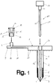
- Fig. 1
- eine bevorzugte Ausführungsform der Katheteranordnung umfassend Katheter, Adapterstück und Mandrin in schematischer Darstellung,
- Fig. 2
- den Katheter von Fig. 1 in der Draufsicht,
- Fig. 3
- einen Schnitt durch den Katheterschlauch einer weiteren Ausführungsform des Katheters,
- Fig. 4
- den Katheter der Ausführungsform von Fig. 3 in der Draufsicht und
- Fig. 5
- einen Ausschnitt des Ringraums einer Ausführungsform des Katheterschlauchs, bei der die Außenwandung des Ballons aus zwei Materialschichten besteht.
- Der Katheter weist eine kreisscheibenförmige sich an der Bauchdecke des Patienten abstützende Platte 1 auf, von der sich ein Katheterschlauch 2 erstreckt. Der Kanal 3 des Katheterschlauchs zum Zuführen einer Nährlösung in das Magenlumen ist an seinem distalen Ende mit einem Lippenventil 4 verschlossen, das zwei sich von dem distalen Ende des Schlauchs erstreckende Lippen 5, 5' aufweist, die dicht aufeinanderliegen. Das Lippenventil 4 erlaubt zwar eine Flüssigkeitsströmung aus dem Katheterschlauch 2 in das Magenlumen, eine umgekehrte Flüssigkeitsströmung ist jedoch nicht möglich. Die kreisscheibenförmige Stützplatte 1 und der Katheterschlauch 2 mit dem Lippenventil 4 bestehen aus einem flexiblen Material, vorzugsweise Silikon. An der Unterseite der Stützplatte 1 sind zahlreiche Noppen 30 vorgesehen.
- An dem distalen Endstück des Katheterschlauchs 2 ist in dessen Schlauchwandung ein Ringraum 6 ausgebildet, der mit einem Füllmedium, z.B. Luft oder einer Flüssigkeit, gefüllt wird, so daß sich der Katheterschlauch in seinem unteren Teil nach Art eines Ballons aufweitet. Mit dem Bezugszeichen 7 ist die umlaufende Klebestelle bezeichnet, an der das untere Ende der äußeren Schlauchwandung des in axialer Richtung geschlitzten Katheterschlauchs unter Bildung des Ringraums mit der inneren Schlauchwandung verklebt ist.
- Von der Stützplatte 1 des Katheters erstreckt sich in radialer Richtung eine flexible Lasche 8 mit rechteckförmigem Querschnitt, die mit der Stützplatte 1 einstückig ist. An dem freien Ende der Lasche 8 ist ein zylindrisches Konnektorteil 9 angeformt, das aus einem durchstechbaren, selbstdichtenden Material, vorzugsweise dem gleichen Material, z.B. Silikon, wie die Stützplatte, die Lasche und der Katheterschlauch besteht. In dem zylindrischen Konnektorteil 9 ist ein zylindrischer Schacht 10 ausgebildet, der in einen Kanal 11 mündet, der sich durch die Lasche 8 und die Schlauchwandung 12 des Katheters in den Ringraum 6 erstreckt.
- Im Zentrum der Stützplatte 1 des Katheters ist eine zylindrische Ausnehmung 24 vorgesehen, an die sich der Kanal 3 des Katheterschlauchs 2 zum Zuführen einer Nährlösung anschließt. Der Innendurchmesser der Ausnehmung 24 entspricht dem Außendurchmesser des an der Lasche 8 angeformten Konnektorteils 9, so daß dieser zum Verschließen der Füllöffnung in die Ausnehmung eingesteckt werden kann.
- Die Katheteranordnung umfaßt ferner ein Adapterstück 13 für den Anschluß einer Spritze zum Aufblasen des Ballons. Das eine Endstück des Adapterstücks 13 ist als Luer-Lock-Konnektor 14 mit einer trichterförmigen Ausnehmung 15 und einem Außengewinde 16 ausgebildet, während das andere Endstück mit einer zylindrischen Ausnehmung 17 versehen ist, so daß sich das Adapterstück 13 passend auf den zylindrischen Konnektorteil 9 des Katheters 1 aufstecken läßt. Zur besseren Abdichtung können der katheterseitige Konnektorteil 9 und die Ausnehmung 17 des Adapterstücks 13 auch konisch geformt sein.
- In dem Steg 18 zwischen der konischen Ausnehmung 15 und der zylindrischen Ausnehmung 17 des Adapterstücks 13 ist eine angespitzte Kanüle 19 eingesetzt, die sich bis in den Zylinderraum 17 erstreckt und eine Strömungsverbindung zwischen der konischen Ausnehmung 15 und der zylindrischen Ausnehmung 17 herstellt.
- Nach dem Einführen des Katheterschlauchs 2 wird das Adapterstück 13 auf den katheterseitigen Konnektorteil 9 aufgesteckt, wobei die Kanüle 19 den Konnektorteil 9 durchstößt und in den Konnektorschacht 10 der Lasche 8 eindringt. An den Luer-Lock-Anschlußteil 14 wird eine herkömmliche Spritze oder eine Schlauchleitung mit einer Luftpumpe angeschlossen. Dann wird der Ballon mit Luft gefüllt und das Adapterstück 13 wird wieder abgezogen, wobei sich die Öffnung im Konnektorteil 9 wieder selbstdichtend verschließt. Das Adapterstück 13 kann aber auch in eine Spritze oder in den Anschlußteil einer Pumpe integriert sein.
- Um den Katheterschlauch 2 einführen zu können, umfaßt die Katheteranordnung noch einen Mandrin 20, der aus einem runden mit einem Außengewinde 20' versehenen Stab 21 mit einem Griffteil 22 besteht. Unterhalb des Griffteils 22 weist der Stab 21 des Mandrin einen zylindrischen Absatz 23 auf, der bei eingesetztem Mandrin in der Ausnehmung 24 im Zentrum der Stützplatte 1 sitzt. Der Kanal 3 des Katheterschlauchs 2 zum Zuführen der Nährlösung ist mit einem Innengewinde 25 versehen. Vor dem Einführen des Katheterschlauchs wird der Mandrin in das Lumen des Schlauchs eingeschraubt, so daß der Schlauch seine Flexibilität verliert.
- Fig. 3 zeigt das distale Endstück des Katheterschlauchs 26 einer weiteren Ausführungsform des Katheters, während Fig. 4 den Katheter in der Draufsicht zeigt. Der Katheter unterscheidet sich von dem unter Bezugnahme auf die in den Fign. 1 und 2 beschriebenen Ausführungsbeispielen dadurch, daß in dem Katheterschlauch zwei übereinander angeordnete Ballone ausgebildet sind, die sich einzeln aufblasen lassen und eine individuelle Anpassung der Schaftlänge erlauben. In den Fign. 3 und 4 sind die Teile des Katheters, die den Teilen der Ausführungsform gemäß der Fign. 1 und 2 entsprechen, mit den gleichen Bezugszeichen versehen. Die beiden Ringräume 6', 6'' der Ballone sind jeweils über einen in Fig. 3 nicht erkennbaren Kanal in der Schlauchwandung 12 mit einem Konnektorteil verbunden. Der untere Ringraum 6' steht mit dem Konnektorteil 9 an der Lasche 8 des Katheters in Verbindung. Zum Befüllen des oberen Ringraums 6'' ist ein zweiter Konnektorteil 26 an der Stützplatte vorgesehen (Fig. 4). Je nach der Länge des Magenstomas kann nach dem Einführen des Katheters entweder der untere oder der obere Ballon aufgeblasen werden.
- Fig. 5 zeigt einen Ausschnitt einer weiteren Ausführungsform des Katheterschlauchs im Bereich des Ringraums 6. Bei diesem Ausführungsbeispiel besteht die Außenwand des Ballons aus zwei übereinanderliegenden Schichten 27,28 unterschiedlichen Materials. Die innere Schicht 27 besteht aus einem flexiblen abdichtenden Material und die äußere Schicht 28 aus einem härteren Material als die innere Schicht. Die beiden Schichten sind im Bereich des Ringraums nicht flächig miteinander verbunden. Zwischen den Schichten 27,28 ist ein gelartiges Material 29 eingeschlossen, um die Flexibilität zu erhöhen. Die härtere Außenhaut verleiht dem Ballon die notwendige Stabilität und Resistenz.
Claims (13)
- Katheter für die perkutane enterale Ernährung miteinem auf die Bauchdecke auflegbaren Stützkörper (1),einem sich von dem Stützkörper (1) erstreckenden Katheterschlauch (2) mit einem Kanal (3) zum Zuführen einer Nährlösung,mindestens einem am Katheterschlauch (2) vorgesehenen Ballon undmindestens einem Konnektorteil (9) zum Anschluß eines Füllorgans, der über einen Kanal (11) mit dem Ballon in Strömungsverbindung steht,dadurch gekennzeichnet,daß der Konnektorteil (9) zum Anschluß des Füllorgans als mit dem Stützkörper (1) einstückiges Verschlußelement aus einem durchstechbaren, selbstdichtenden Material ausgebildet ist, das den Kanal (11) zum Zuführen des Füllmediums verschließt.
- Katheter nach Anspruch 1, dadurch gekennzeichnet, daß der Konnektorteil (9) ein zylindrischer Körper ist, in den sich der Kanal (11) zum Zuführen des Füllmediums erstreckt.
- Katheter nach Anspruch 1 oder 2, dadurch gekennzeichnet, daß der Stützkörper ein auf die Bauchdecke auflegbares plattenförmiges Element (1) und eine davon abstehende flexible Lasche (8) aufweist, an der der Konnektorteil (9) vorgesehen ist, wobei sich der Kanal (11) zum Zuführen des Füllmediums von dem Konnektorteil (9) durch die Lasche (8), das plattenförmige Element (1) und die Wandung des Katheterschlauchs (2) bis in den Ballon erstreckt.
- Katheter nach Anspruch 3, dadurch gekennzeichnet, daß in dem plattenförmigen Element (1) des Stützkörpers eine in den Kanal (3) zum Zuführen der Nährlösung übergehende zylindrische Ausnehmung (24) vorgesehen ist, die derart ausgebildet ist, daß der an der flexiblen Lasche (8) vorgesehene Konnektorteil (9) passend in die Ausnehmung einsteckbar ist.
- Katheter nach einem der Ansprüche 1 bis 4, dadurch gekennzeichnet, daß der Ballon durch einen Ringraum (6) in der Schlauchwandung des Katheterschlauchs (2) gebildet wird.
- Katheter nach einem der Ansprüche 1 bis 5, dadurch gekennzeichnet, daß an dem Katheterschlauch (2) mehrere übereinander angeordnete Ballone vorgesehen sind, die über jeweils einen Kanal mit jeweils einem Konnektorteil (9, 26) verbunden sind, so daß die Ballone einzeln mit dem Füllmedium befüllbar sind.
- Katheter nach einem der Ansprüche 1 bis 6, dadurch gekennzeichnet, daß die Außenwand des Ballons aus zwei übereinanderliegenden Schichten (27, 28) unterschiedlichen Materials gebildet ist, wobei die innere Schicht (27) aus einem flexiblen abdichtenden Material und die äußere Schicht (28) aus einem härteren Material als die innere Schicht besteht.
- Katheter nach Anspruch 7, dadurch gekennzeichnet, daß zwischen der inneren Schicht (27) und der äußeren Schicht (28) der Ballonaußenwand eine gelartige Masse (29) eingeschlossen ist.
- Katheter nach einem der Ansprüche 1 bis 8, dadurch gekennzeichnet, daß am distalen Ende des Katheterschlauchs (2) ein den Kanal (3) zum Zuführen der Nährlösung verschließendes Lippenventil (4) angeordnet ist.
- Katheter nach einem der Ansprüche 3 bis 9, dadurch gekennzeichnet, daß das plattenförmige Element (1) des Stützkörpers an seiner Unterseite mit vorspringenden Elementen (30), insbesondere Noppen, versehen ist.
- Katheteranordnung mit einem Katheter nach einem der Ansprüche 1 bis 10 und einem passend auf den Konnektorteil des Stützkörpers aufsetzbares Adapterstück (13) zum Anschluß eines Füllorgans, wobei in das Adapterstück eine Kanüle (19) derart integriert ist, daß der Konnektorteil (9) beim Aufsetzen des Adapterstücks zur Herstellung einer Strömungsverbindung zwischen dem Ballon und dem an das Adapterstück anschließbaren Füllorgan durchstoßen wird.
- Katheteranordnung nach Anspruch 11, dadurch gekennzeichnet, daß die Katheteranordnung einen stabförmigen Mandrin (20) umfaßt, der in den Katheterschlauch (2) einschiebbar ist.
- Katheteranordnung nach Anspruch 12, dadurch gekennzeichnet, daß der stabförmige Mandrin (20) mit einem Außengewinde (20') und der Kanal (3) des Katheterschlauchs (2) mit einem Innengewinde (25) versehen ist.
Applications Claiming Priority (2)
| Application Number | Priority Date | Filing Date | Title |
|---|---|---|---|
| DE19533749A DE19533749A1 (de) | 1995-09-12 | 1995-09-12 | Stoma-Gastrostomiesonde mit flacher Rückhalteplatte und optionaler variabler Schaftlänge |
| DE19533749 | 1995-09-12 |
Publications (2)
| Publication Number | Publication Date |
|---|---|
| EP0761198A1 true EP0761198A1 (de) | 1997-03-12 |
| EP0761198B1 EP0761198B1 (de) | 2001-12-12 |
Family
ID=7771946
Family Applications (1)
| Application Number | Title | Priority Date | Filing Date |
|---|---|---|---|
| EP96114109A Expired - Lifetime EP0761198B1 (de) | 1995-09-12 | 1996-09-04 | Katheter für die perkutane enterale Ernährung |
Country Status (7)
| Country | Link |
|---|---|
| EP (1) | EP0761198B1 (de) |
| AT (1) | ATE210419T1 (de) |
| DE (2) | DE19533749A1 (de) |
| DK (1) | DK0761198T3 (de) |
| ES (1) | ES2165949T3 (de) |
| NO (1) | NO311331B1 (de) |
| PT (1) | PT761198E (de) |
Families Citing this family (2)
| Publication number | Priority date | Publication date | Assignee | Title |
|---|---|---|---|---|
| DE10055281B4 (de) * | 2000-11-08 | 2004-12-23 | Fresenius Kabi Deutschland Gmbh | Adapter für eine PEG-Sonde |
| DE10131152B4 (de) * | 2001-04-30 | 2004-05-27 | Nutricia Healthcare S.A. | Medizinisches Ballon-Button-System |
Citations (5)
| Publication number | Priority date | Publication date | Assignee | Title |
|---|---|---|---|---|
| US4102342A (en) * | 1975-12-29 | 1978-07-25 | Taichiro Akiyama | Valved device |
| WO1990012611A1 (en) * | 1989-04-21 | 1990-11-01 | Ash Medical Systems, Inc. | Non-intravascular infusion access device |
| WO1992019314A1 (en) * | 1991-05-03 | 1992-11-12 | Bierman Steven F | Sideport connector for catheterization system |
| US5267969A (en) * | 1992-10-08 | 1993-12-07 | Abbott Laboratories | External retaining device for feeding tube or the like |
| WO1994015655A2 (en) * | 1993-01-07 | 1994-07-21 | Medical Innovations Corporation | Gastrostomy catheter system |
-
1995
- 1995-09-12 DE DE19533749A patent/DE19533749A1/de not_active Withdrawn
-
1996
- 1996-08-28 NO NO19963590A patent/NO311331B1/no unknown
- 1996-09-04 PT PT96114109T patent/PT761198E/pt unknown
- 1996-09-04 EP EP96114109A patent/EP0761198B1/de not_active Expired - Lifetime
- 1996-09-04 DE DE59608419T patent/DE59608419D1/de not_active Expired - Fee Related
- 1996-09-04 AT AT96114109T patent/ATE210419T1/de not_active IP Right Cessation
- 1996-09-04 DK DK96114109T patent/DK0761198T3/da active
- 1996-09-04 ES ES96114109T patent/ES2165949T3/es not_active Expired - Lifetime
Patent Citations (5)
| Publication number | Priority date | Publication date | Assignee | Title |
|---|---|---|---|---|
| US4102342A (en) * | 1975-12-29 | 1978-07-25 | Taichiro Akiyama | Valved device |
| WO1990012611A1 (en) * | 1989-04-21 | 1990-11-01 | Ash Medical Systems, Inc. | Non-intravascular infusion access device |
| WO1992019314A1 (en) * | 1991-05-03 | 1992-11-12 | Bierman Steven F | Sideport connector for catheterization system |
| US5267969A (en) * | 1992-10-08 | 1993-12-07 | Abbott Laboratories | External retaining device for feeding tube or the like |
| WO1994015655A2 (en) * | 1993-01-07 | 1994-07-21 | Medical Innovations Corporation | Gastrostomy catheter system |
Also Published As
| Publication number | Publication date |
|---|---|
| ATE210419T1 (de) | 2001-12-15 |
| NO963590D0 (no) | 1996-08-28 |
| DE19533749A1 (de) | 1997-03-13 |
| PT761198E (pt) | 2002-05-31 |
| NO963590L (no) | 1997-03-13 |
| EP0761198B1 (de) | 2001-12-12 |
| DK0761198T3 (da) | 2002-03-18 |
| NO311331B1 (no) | 2001-11-19 |
| DE59608419D1 (de) | 2002-01-24 |
| ES2165949T3 (es) | 2002-04-01 |
Similar Documents
| Publication | Publication Date | Title |
|---|---|---|
| DE69728281T2 (de) | Vorrichtung für den chirurgischen Zugang zu einer Körperhöhle | |
| DE60013092T2 (de) | Ballonkatheter für den Magen mit verbesserter Ballonorientierung | |
| DE60112550T2 (de) | Implantierbare vorrichtung zur arzneimittelinjektion | |
| DE4105661C2 (de) | ||
| DE60030451T2 (de) | Einstellbares magenimplantat | |
| DE69631045T2 (de) | Gastrostomie-Ernährungsanschlüsse mit einwandfrei abdichtenden Eintrittsventilen | |
| DE102006053219B4 (de) | Tropfkammer für ein Infusionsgerät und Infusionsgerät mit einer Tropfkammer sowie Anordnung bestehend aus einem Infusionsbehältnis und einem Infusionsgerät | |
| DE1675448A1 (de) | Einweg-Durchflussventil | |
| CH691726A5 (de) | Konnektierungssystem für medizinische Anwendungen. | |
| EP0287998A2 (de) | Gastral/duodenal/jejunal-Katheter für die percutane enterale Ernährung | |
| WO2010115598A1 (de) | Verbindungsstück für den sondenschlauch einer enteralen ernährungssonde und anordnung aus einer enteralen ernährungssonde und einem enteralen überleitsystem | |
| WO1995029661A1 (de) | Einstückige appliziervorrichtung zur kontaminationsfreien verabreichung von arzneimitteln (zytostatika) | |
| DE2735086A1 (de) | Katheter zur untersuchung oder behandlung eines blutgefaesses, nebst geraet zum einsatz des katheters | |
| EP1331962B1 (de) | Adapter für eine peg-sonde | |
| DE3919740A1 (de) | Geraet zum einsetzen einer suprapubischen blasenfistel | |
| DE19634116C2 (de) | Katheter für die perkutane enterale Ernährung | |
| EP1331912B1 (de) | Adapter für eine peg-sonde | |
| DE10139644B4 (de) | Montageteil für einen Adapter einer PEG-Sonde und Adapter für eine PEG-Sonde mit einem derartigen Montageteil | |
| EP2931135A1 (de) | Ballonkatheter zur behandlung enteroatmosphärischer fisteln bei offenen abdomen | |
| DE2918326A1 (de) | Mit einer kunststoffkanuele verbundenes anschlusstueck | |
| EP0761198B1 (de) | Katheter für die perkutane enterale Ernährung | |
| WO2003039383A1 (de) | Mandrin für einen katheter, längenmesser zur bestimmung der stomalänge und set zur enteralen ernährung | |
| DE3731590C1 (en) | Medical probe | |
| DE1541237B2 (de) | Trokar | |
| DE10051593C2 (de) | PEG-Sonden-Adapter |
Legal Events
| Date | Code | Title | Description |
|---|---|---|---|
| PUAI | Public reference made under article 153(3) epc to a published international application that has entered the european phase |
Free format text: ORIGINAL CODE: 0009012 |
|
| AK | Designated contracting states |
Kind code of ref document: A1 Designated state(s): AT BE CH DE DK ES FI FR GB GR IE IT LI LU NL PT SE |
|
| 17P | Request for examination filed |
Effective date: 19970715 |
|
| GRAG | Despatch of communication of intention to grant |
Free format text: ORIGINAL CODE: EPIDOS AGRA |
|
| 17Q | First examination report despatched |
Effective date: 20001103 |
|
| GRAG | Despatch of communication of intention to grant |
Free format text: ORIGINAL CODE: EPIDOS AGRA |
|
| GRAG | Despatch of communication of intention to grant |
Free format text: ORIGINAL CODE: EPIDOS AGRA |
|
| GRAH | Despatch of communication of intention to grant a patent |
Free format text: ORIGINAL CODE: EPIDOS IGRA |
|
| RBV | Designated contracting states (corrected) |
Designated state(s): AT BE CH DE DK ES FI FR GB GR IE IT LI LU NL PT SE |
|
| GRAH | Despatch of communication of intention to grant a patent |
Free format text: ORIGINAL CODE: EPIDOS IGRA |
|
| GRAA | (expected) grant |
Free format text: ORIGINAL CODE: 0009210 |
|
| AK | Designated contracting states |
Kind code of ref document: B1 Designated state(s): AT BE CH DE DK ES FI FR GB GR IE IT LI LU NL PT SE |
|
| REF | Corresponds to: |
Ref document number: 210419 Country of ref document: AT Date of ref document: 20011215 Kind code of ref document: T |
|
| REG | Reference to a national code |
Ref country code: CH Ref legal event code: EP |
|
| REG | Reference to a national code |
Ref country code: GB Ref legal event code: IF02 |
|
| REG | Reference to a national code |
Ref country code: IE Ref legal event code: FG4D Free format text: GERMAN |
|
| REF | Corresponds to: |
Ref document number: 59608419 Country of ref document: DE Date of ref document: 20020124 |
|
| REG | Reference to a national code |
Ref country code: DK Ref legal event code: T3 |
|
| GBT | Gb: translation of ep patent filed (gb section 77(6)(a)/1977) |
Effective date: 20020225 |
|
| REG | Reference to a national code |
Ref country code: ES Ref legal event code: FG2A Ref document number: 2165949 Country of ref document: ES Kind code of ref document: T3 |
|
| ET | Fr: translation filed | ||
| REG | Reference to a national code |
Ref country code: PT Ref legal event code: SC4A Free format text: AVAILABILITY OF NATIONAL TRANSLATION Effective date: 20020306 |
|
| REG | Reference to a national code |
Ref country code: GR Ref legal event code: EP Ref document number: 20020400973 Country of ref document: GR |
|
| PGFP | Annual fee paid to national office [announced via postgrant information from national office to epo] |
Ref country code: GB Payment date: 20020814 Year of fee payment: 7 |
|
| PGFP | Annual fee paid to national office [announced via postgrant information from national office to epo] |
Ref country code: GR Payment date: 20020822 Year of fee payment: 7 |
|
| PGFP | Annual fee paid to national office [announced via postgrant information from national office to epo] |
Ref country code: IE Payment date: 20020826 Year of fee payment: 7 |
|
| PGFP | Annual fee paid to national office [announced via postgrant information from national office to epo] |
Ref country code: PT Payment date: 20020904 Year of fee payment: 7 |
|
| PGFP | Annual fee paid to national office [announced via postgrant information from national office to epo] |
Ref country code: NL Payment date: 20020916 Year of fee payment: 7 Ref country code: FR Payment date: 20020916 Year of fee payment: 7 |
|
| PGFP | Annual fee paid to national office [announced via postgrant information from national office to epo] |
Ref country code: DK Payment date: 20020918 Year of fee payment: 7 |
|
| PGFP | Annual fee paid to national office [announced via postgrant information from national office to epo] |
Ref country code: AT Payment date: 20020919 Year of fee payment: 7 |
|
| PGFP | Annual fee paid to national office [announced via postgrant information from national office to epo] |
Ref country code: SE Payment date: 20020920 Year of fee payment: 7 Ref country code: FI Payment date: 20020920 Year of fee payment: 7 Ref country code: CH Payment date: 20020920 Year of fee payment: 7 Ref country code: BE Payment date: 20020920 Year of fee payment: 7 |
|
| PGFP | Annual fee paid to national office [announced via postgrant information from national office to epo] |
Ref country code: LU Payment date: 20020923 Year of fee payment: 7 |
|
| PGFP | Annual fee paid to national office [announced via postgrant information from national office to epo] |
Ref country code: ES Payment date: 20020926 Year of fee payment: 7 |
|
| PLBE | No opposition filed within time limit |
Free format text: ORIGINAL CODE: 0009261 |
|
| STAA | Information on the status of an ep patent application or granted ep patent |
Free format text: STATUS: NO OPPOSITION FILED WITHIN TIME LIMIT |
|
| PGFP | Annual fee paid to national office [announced via postgrant information from national office to epo] |
Ref country code: DE Payment date: 20021116 Year of fee payment: 7 |
|
| 26N | No opposition filed | ||
| PG25 | Lapsed in a contracting state [announced via postgrant information from national office to epo] |
Ref country code: LU Free format text: LAPSE BECAUSE OF NON-PAYMENT OF DUE FEES Effective date: 20030904 Ref country code: IE Free format text: LAPSE BECAUSE OF NON-PAYMENT OF DUE FEES Effective date: 20030904 Ref country code: GB Free format text: LAPSE BECAUSE OF NON-PAYMENT OF DUE FEES Effective date: 20030904 Ref country code: FI Free format text: LAPSE BECAUSE OF NON-PAYMENT OF DUE FEES Effective date: 20030904 Ref country code: AT Free format text: LAPSE BECAUSE OF NON-PAYMENT OF DUE FEES Effective date: 20030904 |
|
| PG25 | Lapsed in a contracting state [announced via postgrant information from national office to epo] |
Ref country code: SE Free format text: LAPSE BECAUSE OF NON-PAYMENT OF DUE FEES Effective date: 20030905 Ref country code: ES Free format text: LAPSE BECAUSE OF NON-PAYMENT OF DUE FEES Effective date: 20030905 |
|
| PG25 | Lapsed in a contracting state [announced via postgrant information from national office to epo] |
Ref country code: LI Free format text: LAPSE BECAUSE OF NON-PAYMENT OF DUE FEES Effective date: 20030930 Ref country code: DK Free format text: LAPSE BECAUSE OF NON-PAYMENT OF DUE FEES Effective date: 20030930 Ref country code: CH Free format text: LAPSE BECAUSE OF NON-PAYMENT OF DUE FEES Effective date: 20030930 Ref country code: BE Free format text: LAPSE BECAUSE OF NON-PAYMENT OF DUE FEES Effective date: 20030930 |
|
| BERE | Be: lapsed |
Owner name: *FRESENIUS A.G. Effective date: 20030930 |
|
| PG25 | Lapsed in a contracting state [announced via postgrant information from national office to epo] |
Ref country code: PT Free format text: LAPSE BECAUSE OF NON-PAYMENT OF DUE FEES Effective date: 20040331 |
|
| PG25 | Lapsed in a contracting state [announced via postgrant information from national office to epo] |
Ref country code: NL Free format text: LAPSE BECAUSE OF NON-PAYMENT OF DUE FEES Effective date: 20040401 Ref country code: DE Free format text: LAPSE BECAUSE OF NON-PAYMENT OF DUE FEES Effective date: 20040401 |
|
| PG25 | Lapsed in a contracting state [announced via postgrant information from national office to epo] |
Ref country code: GR Free format text: LAPSE BECAUSE OF NON-PAYMENT OF DUE FEES Effective date: 20040402 |
|
| GBPC | Gb: european patent ceased through non-payment of renewal fee | ||
| EUG | Se: european patent has lapsed | ||
| REG | Reference to a national code |
Ref country code: DK Ref legal event code: EBP |
|
| REG | Reference to a national code |
Ref country code: CH Ref legal event code: PL |
|
| PG25 | Lapsed in a contracting state [announced via postgrant information from national office to epo] |
Ref country code: FR Free format text: LAPSE BECAUSE OF NON-PAYMENT OF DUE FEES Effective date: 20040528 |
|
| NLV4 | Nl: lapsed or anulled due to non-payment of the annual fee |
Effective date: 20040401 |
|
| REG | Reference to a national code |
Ref country code: PT Ref legal event code: MM4A Free format text: LAPSE DUE TO NON-PAYMENT OF FEES Effective date: 20040331 Ref country code: IE Ref legal event code: MM4A |
|
| REG | Reference to a national code |
Ref country code: FR Ref legal event code: ST |
|
| REG | Reference to a national code |
Ref country code: ES Ref legal event code: FD2A Effective date: 20030905 |
|
| PG25 | Lapsed in a contracting state [announced via postgrant information from national office to epo] |
Ref country code: IT Free format text: LAPSE BECAUSE OF NON-PAYMENT OF DUE FEES Effective date: 20050904 |