EP1331116A2 - Luftdüse - Google Patents
Luftdüse Download PDFInfo
- Publication number
- EP1331116A2 EP1331116A2 EP03000826A EP03000826A EP1331116A2 EP 1331116 A2 EP1331116 A2 EP 1331116A2 EP 03000826 A EP03000826 A EP 03000826A EP 03000826 A EP03000826 A EP 03000826A EP 1331116 A2 EP1331116 A2 EP 1331116A2
- Authority
- EP
- European Patent Office
- Prior art keywords
- opening
- guide element
- air
- air nozzle
- wall elements
- Prior art date
- Legal status (The legal status is an assumption and is not a legal conclusion. Google has not performed a legal analysis and makes no representation as to the accuracy of the status listed.)
- Granted
Links
Images

Classifications
-
- B—PERFORMING OPERATIONS; TRANSPORTING
- B60—VEHICLES IN GENERAL
- B60H—ARRANGEMENTS OF HEATING, COOLING, VENTILATING OR OTHER AIR-TREATING DEVICES SPECIALLY ADAPTED FOR PASSENGER OR GOODS SPACES OF VEHICLES
- B60H1/00—Heating, cooling or ventilating devices
- B60H1/34—Nozzles; Air-diffusers
- B60H1/3414—Nozzles; Air-diffusers with means for adjusting the air stream direction
- B60H1/3421—Nozzles; Air-diffusers with means for adjusting the air stream direction using only pivoting shutters
-
- B—PERFORMING OPERATIONS; TRANSPORTING
- B60—VEHICLES IN GENERAL
- B60H—ARRANGEMENTS OF HEATING, COOLING, VENTILATING OR OTHER AIR-TREATING DEVICES SPECIALLY ADAPTED FOR PASSENGER OR GOODS SPACES OF VEHICLES
- B60H1/00—Heating, cooling or ventilating devices
- B60H1/34—Nozzles; Air-diffusers
- B60H2001/3471—Details of actuators
Definitions
- the invention relates to an air nozzle for ventilation an interior of a motor vehicle with at least a guide element arranged in a nozzle housing for Steering of exiting from an opening in the nozzle housing Air and with an adjustment device for adjustment of the guide element.
- Such an air nozzle is, for example, from the EP 0 397 909 B1 is known.
- the slats allow the swivel axis to be arranged vertically a guide of the emerging from the air nozzle Airflow in a horizontal plane.
- a disadvantage of the known air nozzle is that the slats for their pivoting in the area of the opening have a large space requirement. A great room for however, the opening is particularly in a dashboard of a motor vehicle arranged air nozzles often not available.
- the invention is based on the problem, a Air nozzle of the type mentioned in such a way that it has a particularly small footprint.
- this problem is solved by that fixed wall elements with the nozzle housing in the intended outflow directions at an angle to the level of Are aligned and that the guide element for Throttling and / or directing the flow on the wall elements is designed.
- This design allows the area Keep the opening particularly small because of the direction of outflow essentially from those fixed with the nozzle housing and therefore non-swiveling wall elements is set.
- the guide elements direct the flow of the Air optionally directed in one direction Wall elements or on the other way aligned wall elements and can therefore inside Area of the nozzle housing may be arranged. Therefore leaves the opening of the air nozzle according to the invention in particular keep it small.
- Another advantage of this design is in that the contour of the opening of the nozzle housing the intended contour one to the invention Air nozzle adjacent dashboard of the motor vehicle can be adjusted.
- the wall elements can, for example, be fixed Be designed slats.
- the invention Air nozzle requires very few to be installed Components if the wall elements as side walls of the Nozzle housing are formed.
- the air nozzle according to the invention is designed structurally particularly simple when the nozzle housing is close the opening for creating the wall elements arcuate is designed.
- the one adjacent to the opening Area optionally designed spherical or cylindrical his. Therefore the outflow direction can be Use of a suitable guide element in the horizontal Adjust the level and the vertical level.
- the setting of the guide element designed according to another advantageous development of the Invention particularly convenient when the guide element in Direction of flow seen in front of the arcuate area is arranged and if a coupled to the guide element Actuator is guided up to the opening.
- This design allows the flow of air to be targeted Steer onto one of the wall elements and deflect from it. The other of the wall elements therefore does not contribute Directing the air at.
- the adjustment device requires thereby a particularly low structural Expenditure.
- Figure 1 shows an air nozzle with a cylindrical Nozzle housing 1.
- the nozzle housing 1 has an opening 2 for the outflow of air and a channel 3, through which the Air is introduced into the nozzle housing 1.
- At the opening 2 adjoin wall elements 4, 5 of the nozzle housing 1.
- Within the nozzle housing 1 there are several pivotable Slats 6 and a likewise pivotable guide element 7 arranged.
- the slats 6 are used to adjust the Outflow direction, for example, in the vertical plane the air nozzle, while the guide element 7 Outflow direction, for example in the horizontal plane can be adjusted.
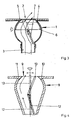
- Figure 2 shows in a sectional view the air nozzle of Figure 1 along the line II - II that the wall elements 4, 5 are oriented obliquely to the plane of the opening 2 are.
- the guide element 7 is perpendicular to one axis pivoting to the plane of the drawing and is aligned in an area between the wall elements 4, 5. This will keep the flow straight Paths through the nozzle housing 1.
- the flow of air with double arrows characterized.
- Figure 3 shows the air nozzle of Figure 2 after a Swiveling the guide element 7. This will Flow of air on one of the curved wall elements 5 directed so that the air is guided by this wall element 5 becomes. On the opposite wall element 4 throttled the flow of air. So that is the outflow direction the air from the opening 2 depending on the Position of the guide element 7. The wall element 5, on which the air is guided along, determines the outflow direction the air from the opening 2 firmly.
- FIG. 4 shows a further embodiment of the Air nozzle in longitudinal section, in which a nozzle housing 8 close an opening 9 to form a hemisphere wall elements 10, 11 has.
- a guide element 12 is pivotally mounted inside the nozzle housing 8 .
- the guiding element 12 is with an also pivotally mounted actuator 13 coupled.
- the control element 13 protrudes slightly out of the opening 9 of the nozzle housing 8 and can be placed around a perpendicular to the drawing plane Swivel the axis and about a perpendicular to the opening 9 Turn the pointing axis.
- the guide element 12 pivoted or rotated and directs the air onto the Wall elements 10, 11 near the opening 9.
Landscapes
- Physics & Mathematics (AREA)
- Thermal Sciences (AREA)
- Engineering & Computer Science (AREA)
- Mechanical Engineering (AREA)
- Air-Flow Control Members (AREA)
Abstract
Description
- Fig. 1
- eine perspektivische Darstellung einer erfindungsgemäßen Luftdüse,
- Fig. 2
- eine Schnittdarstellung durch die Luftdüse aus Figur 1 entlang der Linie II - II,
- Fig. 3
- die Luftdüse aus Figur 2 nach einer Verstellung eines Leitelementes,
- Fig. 4
- eine Schnittdarstellung durch eine weitere Ausführungsform der erfindungsgemäßen Luftdüse.
- 1
- Düsengehäuse
- 2
- Öffnung
- 3
- Kanal
- 4, 5
- Wandelement
- 6
- Lamelle
- 7
- Leitelement
- 8
- Düsengehäuse
- 9
- Öffnung
- 10, 11
- Wandelement
- 12
- Leitelement
- 13
- Stellelement
Claims (6)
- Luftdüse zur Belüftung eines Innenraums eines Kraftfahrzeuges mit zumindest einem in einem Düsengehäuse angeordneten Leitelement zur Lenkung von aus einer Öffnung im Düsengehäuse austretender Luft und mit einer Verstelleinrichtung zur Verstellung des Leitelementes, dadurch gekennzeichnet, dass mit dem Düsengehäuse (1, 8) feststehende Wandelemente (4, 5, 10, 11) in vorgesehenen Ausströmrichtungen schräg zur Ebene der Öffnung (2, 9) ausgerichtet sind und dass das Leitelement (7, 12) zur Drosselung und/oder Lenkung der Strömung an den Wandelementen (4, 5, 10, 11) gestaltet ist.
- Luftdüse nach Anspruch 1, dadurch gekennzeichnet, dass die Wandelemente (4, 5, 10, 11) als Seitenwandungen des Düsengehäuses (1, 8) ausgebildet sind.
- Luftdüse nach Anspruch 1 oder 2, dadurch gekennzeichnet, dass das Düsengehäuse (1, 8) nahe der Öffnung (2, 9) zur Erzeugung der Wandelemente bogenförmig gestaltet ist.
- Luftdüse nach zumindest einem der vorhergehenden Ansprüche, dadurch gekennzeichnet, dass das Leitelement (12) in Strömungsrichtung gesehen vor dem bogenförmigen Bereich angeordnet ist und dass ein mit dem Leitelement (12) gekoppeltes Stellelement (13) bis zu der Öffnung (9) geführt ist.
- Luftdüse nach zumindest einem der vorhergehenden Ansprüche, dadurch gekennzeichnet, dass das Leitelement (12) um eine senkrecht zur Öffnung (9) weisende Achse drehbar und um eine parallel zur Öffnung (9) angeordnete Achse schwenkbar gelagert ist.
- Luftdüse nach zumindest einem der vorhergehenden Ansprüche, dadurch gekennzeichnet, dass das Leitelement wahlweise gegen das eine Wandelement oder gegen das andere Wandelement schwenkbar gelagert ist.
Applications Claiming Priority (2)
| Application Number | Priority Date | Filing Date | Title |
|---|---|---|---|
| DE2002102926 DE10202926A1 (de) | 2002-01-25 | 2002-01-25 | Luftdüse |
| DE10202926 | 2002-01-25 |
Publications (3)
| Publication Number | Publication Date |
|---|---|
| EP1331116A2 true EP1331116A2 (de) | 2003-07-30 |
| EP1331116A3 EP1331116A3 (de) | 2004-04-28 |
| EP1331116B1 EP1331116B1 (de) | 2006-06-14 |
Family
ID=7713076
Family Applications (1)
| Application Number | Title | Priority Date | Filing Date |
|---|---|---|---|
| EP20030000826 Expired - Lifetime EP1331116B1 (de) | 2002-01-25 | 2003-01-15 | Luftdüse |
Country Status (3)
| Country | Link |
|---|---|
| EP (1) | EP1331116B1 (de) |
| DE (2) | DE10202926A1 (de) |
| ES (1) | ES2266648T3 (de) |
Cited By (10)
| Publication number | Priority date | Publication date | Assignee | Title |
|---|---|---|---|---|
| US9513027B2 (en) | 2013-05-29 | 2016-12-06 | Faurecia Innenraum Systeme Gmbh | Air vent |
| EP3231647A1 (de) * | 2016-04-14 | 2017-10-18 | Fischer Automotive Systems GmbH & Co. KG | Luftausströmer |
| WO2017182318A1 (de) * | 2016-04-19 | 2017-10-26 | Dr. Schneider Kunststoffwerke Gmbh | Luftausströmer mit einer einrichtung zum steuern eines luftstroms |
| EP3378686A1 (de) * | 2017-03-23 | 2018-09-26 | Dr. Schneider Kunststoffwerke GmbH | Luftausströmer |
| US10195924B2 (en) | 2013-05-29 | 2019-02-05 | Faurecia Innenraum Systeme Gmbh | Air vent |
| DE102017118055A1 (de) * | 2017-08-09 | 2019-02-14 | Fischer Automotive Systems Gmbh & Co. Kg | Luftausströmer |
| EP3632726A1 (de) | 2018-10-05 | 2020-04-08 | Seat, S.A. | Luftverteiler für ein fahrzeug |
| EP3632725A1 (de) | 2018-10-05 | 2020-04-08 | Seat, S.A. | Luftverteiler für ein fahrzeug |
| US10792979B2 (en) | 2016-06-15 | 2020-10-06 | Dr. Schneider Kunststoffwerke Gmbh | Air vent |
| EP4046836A1 (de) | 2021-02-08 | 2022-08-24 | Seat, S.A. | Luftverteiler für ein fahrzeug |
Families Citing this family (9)
| Publication number | Priority date | Publication date | Assignee | Title |
|---|---|---|---|---|
| DE102006002663B4 (de) * | 2006-01-19 | 2016-09-22 | GM Global Technology Operations LLC (n. d. Ges. d. Staates Delaware) | Ausströmdüse mit Lamellen und Kraftfahrzeug mit Innenraum |
| JP6428004B2 (ja) | 2014-07-10 | 2018-11-28 | 株式会社デンソー | 送風装置 |
| DE102016122138A1 (de) * | 2016-11-17 | 2018-05-17 | Dr. Schneider Kunststoffwerke Gmbh | Luftausströmer |
| DE102016122142B4 (de) * | 2016-11-17 | 2021-07-15 | Dr. Schneider Kunststoffwerke Gmbh | Luftausströmer |
| DE102018203076A1 (de) | 2018-03-01 | 2019-09-05 | Volkswagen Aktiengesellschaft | Lüftungsvorrichtung und Kraftfahrzeug |
| DE102018109994A1 (de) * | 2018-04-25 | 2019-10-31 | Dr. Schneider Kunststoffwerke Gmbh | Luftausströmer |
| DE202018104942U1 (de) | 2018-04-25 | 2018-09-10 | Dr. Schneider Kunststoffwerke Gmbh | Luftausströmer |
| DE102018214560A1 (de) * | 2018-08-28 | 2020-03-05 | Faurecia Innenraum Systeme Gmbh | Luftauslass |
| DE102022206301A1 (de) | 2022-06-23 | 2023-12-28 | Faurecia Innenraum Systeme Gmbh | Fahrzeuglüftungsvorrichtung mit flexiblen Flügel |
Citations (1)
| Publication number | Priority date | Publication date | Assignee | Title |
|---|---|---|---|---|
| EP0397909B1 (de) | 1989-05-19 | 1992-07-22 | Siemens Aktiengesellschaft | Luftverteilungsvorrichtung |
Family Cites Families (4)
| Publication number | Priority date | Publication date | Assignee | Title |
|---|---|---|---|---|
| DE2230239A1 (de) * | 1972-06-21 | 1974-01-17 | Volkswagenwerk Ag | Ausstroemerduese, insbesondere fuer die belueftung von kraftfahrzeugen |
| US5238448A (en) * | 1989-04-19 | 1993-08-24 | Toyoda Gosei Co., Ltd. | Air-conditioning grille |
| DE19943876A1 (de) * | 1999-09-14 | 2001-03-15 | Volkswagen Ag | Luftausströmer für den hinteren Fahrgastraum in Kraftfahrzeugen |
| DE10029365A1 (de) * | 2000-06-15 | 2001-12-20 | Behr Gmbh & Co | Ausströmer für eine Belüftungsanlage, insbesondere für ein Kraftfahrzeug |
-
2002
- 2002-01-25 DE DE2002102926 patent/DE10202926A1/de not_active Withdrawn
-
2003
- 2003-01-15 EP EP20030000826 patent/EP1331116B1/de not_active Expired - Lifetime
- 2003-01-15 ES ES03000826T patent/ES2266648T3/es not_active Expired - Lifetime
- 2003-01-15 DE DE50303760T patent/DE50303760D1/de not_active Expired - Lifetime
Patent Citations (1)
| Publication number | Priority date | Publication date | Assignee | Title |
|---|---|---|---|---|
| EP0397909B1 (de) | 1989-05-19 | 1992-07-22 | Siemens Aktiengesellschaft | Luftverteilungsvorrichtung |
Cited By (16)
| Publication number | Priority date | Publication date | Assignee | Title |
|---|---|---|---|---|
| US11400795B2 (en) | 2013-05-29 | 2022-08-02 | Faurecia Innenraum Systeme Gmbh | Air vent |
| US11878573B2 (en) | 2013-05-29 | 2024-01-23 | Faurecia Innenraum Systeme Gmbh | Air vent |
| US10195924B2 (en) | 2013-05-29 | 2019-02-05 | Faurecia Innenraum Systeme Gmbh | Air vent |
| US10408490B2 (en) | 2013-05-29 | 2019-09-10 | Faurecia Innenraum Systeme Gmbh | Air vent |
| US12365223B2 (en) | 2013-05-29 | 2025-07-22 | Faurecia Innenraum Systeme Gmbh | Air vent |
| US9513027B2 (en) | 2013-05-29 | 2016-12-06 | Faurecia Innenraum Systeme Gmbh | Air vent |
| CN107298007A (zh) * | 2016-04-14 | 2017-10-27 | 费希尔汽车系统有限责任两合公司 | 排气装置 |
| EP3231647A1 (de) * | 2016-04-14 | 2017-10-18 | Fischer Automotive Systems GmbH & Co. KG | Luftausströmer |
| CN107298007B (zh) * | 2016-04-14 | 2019-09-03 | 费希尔汽车系统有限责任两合公司 | 排气装置 |
| WO2017182318A1 (de) * | 2016-04-19 | 2017-10-26 | Dr. Schneider Kunststoffwerke Gmbh | Luftausströmer mit einer einrichtung zum steuern eines luftstroms |
| US10792979B2 (en) | 2016-06-15 | 2020-10-06 | Dr. Schneider Kunststoffwerke Gmbh | Air vent |
| EP3378686A1 (de) * | 2017-03-23 | 2018-09-26 | Dr. Schneider Kunststoffwerke GmbH | Luftausströmer |
| DE102017118055A1 (de) * | 2017-08-09 | 2019-02-14 | Fischer Automotive Systems Gmbh & Co. Kg | Luftausströmer |
| EP3632726A1 (de) | 2018-10-05 | 2020-04-08 | Seat, S.A. | Luftverteiler für ein fahrzeug |
| EP3632725A1 (de) | 2018-10-05 | 2020-04-08 | Seat, S.A. | Luftverteiler für ein fahrzeug |
| EP4046836A1 (de) | 2021-02-08 | 2022-08-24 | Seat, S.A. | Luftverteiler für ein fahrzeug |
Also Published As
| Publication number | Publication date |
|---|---|
| DE50303760D1 (de) | 2006-07-27 |
| EP1331116A3 (de) | 2004-04-28 |
| ES2266648T3 (es) | 2007-03-01 |
| EP1331116B1 (de) | 2006-06-14 |
| DE10202926A1 (de) | 2003-07-31 |
Similar Documents
| Publication | Publication Date | Title |
|---|---|---|
| EP1331116A2 (de) | Luftdüse | |
| DE102006002663B4 (de) | Ausströmdüse mit Lamellen und Kraftfahrzeug mit Innenraum | |
| DE19504737A1 (de) | Kraftfahrzeug-Gebläsegrill | |
| EP3321114A1 (de) | Luftausströmer | |
| DE102016116356A1 (de) | Luftausströmer | |
| DE102006032587B4 (de) | Luftausströmeinrichtung für Fahrzeuge | |
| EP3321113B1 (de) | Luftausströmer | |
| DE102020131095A1 (de) | Lüftungseinrichtung | |
| DE2230239A1 (de) | Ausstroemerduese, insbesondere fuer die belueftung von kraftfahrzeugen | |
| DE3509537C2 (de) | ||
| DE102019210048A1 (de) | Luftausströmer | |
| EP1204538B1 (de) | Luftausströmer mit lamellen | |
| DE202007010190U1 (de) | Luftdüse | |
| DE3333878A1 (de) | Belueftungsduese | |
| DE202005012570U1 (de) | Luftdüse | |
| DE19711679B4 (de) | Vorrichtung und Verfahren zur Regelung einer Luftströmung | |
| DE102016122138A1 (de) | Luftausströmer | |
| DE102022207513B4 (de) | Luftausströmer für ein Fahrzeug | |
| DE102009020574B3 (de) | Luftauslassdüse | |
| DE202004015522U1 (de) | Lamellenanordnung für eine Luftdüse | |
| EP0937596B1 (de) | Luftstromverteiler | |
| DE102005037748B3 (de) | Luftdüse | |
| EP1331117A2 (de) | Luftdüse zur Belüftung eines Innenraums eines Kraftfahrzeuges | |
| DE102005015222B3 (de) | Luftdüse | |
| DE102019100992B4 (de) | Luftablenkeinrichtung für einen Luftausströmer und Luftausströmer |
Legal Events
| Date | Code | Title | Description |
|---|---|---|---|
| PUAI | Public reference made under article 153(3) epc to a published international application that has entered the european phase |
Free format text: ORIGINAL CODE: 0009012 |
|
| AK | Designated contracting states |
Designated state(s): AT BE BG CH CY CZ DE DK EE ES FI FR GB GR HU IE IT LI LU MC NL PT SE SI SK TR |
|
| AX | Request for extension of the european patent |
Extension state: AL LT LV MK RO |
|
| PUAL | Search report despatched |
Free format text: ORIGINAL CODE: 0009013 |
|
| AK | Designated contracting states |
Kind code of ref document: A3 Designated state(s): AT BE BG CH CY CZ DE DK EE ES FI FR GB GR HU IE IT LI LU MC NL PT SE SI SK TR |
|
| AX | Request for extension of the european patent |
Extension state: AL LT LV MK RO |
|
| 17P | Request for examination filed |
Effective date: 20040816 |
|
| AKX | Designation fees paid |
Designated state(s): DE ES FR GB |
|
| 17Q | First examination report despatched |
Effective date: 20041209 |
|
| GRAP | Despatch of communication of intention to grant a patent |
Free format text: ORIGINAL CODE: EPIDOSNIGR1 |
|
| GRAS | Grant fee paid |
Free format text: ORIGINAL CODE: EPIDOSNIGR3 |
|
| GRAA | (expected) grant |
Free format text: ORIGINAL CODE: 0009210 |
|
| AK | Designated contracting states |
Kind code of ref document: B1 Designated state(s): DE ES FR GB |
|
| REG | Reference to a national code |
Ref country code: GB Ref legal event code: FG4D Free format text: NOT ENGLISH |
|
| REF | Corresponds to: |
Ref document number: 50303760 Country of ref document: DE Date of ref document: 20060727 Kind code of ref document: P |
|
| GBT | Gb: translation of ep patent filed (gb section 77(6)(a)/1977) |
Effective date: 20060906 |
|
| ET | Fr: translation filed | ||
| REG | Reference to a national code |
Ref country code: ES Ref legal event code: FG2A Ref document number: 2266648 Country of ref document: ES Kind code of ref document: T3 |
|
| PLBE | No opposition filed within time limit |
Free format text: ORIGINAL CODE: 0009261 |
|
| STAA | Information on the status of an ep patent application or granted ep patent |
Free format text: STATUS: NO OPPOSITION FILED WITHIN TIME LIMIT |
|
| 26N | No opposition filed |
Effective date: 20070315 |
|
| REG | Reference to a national code |
Ref country code: GB Ref legal event code: 732E Free format text: REGISTERED BETWEEN 20090219 AND 20090225 |
|
| REG | Reference to a national code |
Ref country code: GB Ref legal event code: 732E Free format text: REGISTERED BETWEEN 20090305 AND 20090311 |
|
| REG | Reference to a national code |
Ref country code: GB Ref legal event code: 732E Free format text: REGISTERED BETWEEN 20091029 AND 20091104 |
|
| REG | Reference to a national code |
Ref country code: GB Ref legal event code: 732E Free format text: REGISTERED BETWEEN 20091105 AND 20091111 |
|
| REG | Reference to a national code |
Ref country code: DE Ref legal event code: R081 Ref document number: 50303760 Country of ref document: DE Owner name: GM GLOBAL TECHNOLOGY OPERATIONS LLC (N. D. GES, US Free format text: FORMER OWNER: GM GLOBAL TECHNOLOGY OPERATIONS, INC., DETROIT, MICH., US Effective date: 20110323 |
|
| PGFP | Annual fee paid to national office [announced via postgrant information from national office to epo] |
Ref country code: ES Payment date: 20130207 Year of fee payment: 11 Ref country code: DE Payment date: 20130109 Year of fee payment: 11 Ref country code: GB Payment date: 20130109 Year of fee payment: 11 Ref country code: FR Payment date: 20130204 Year of fee payment: 11 |
|
| REG | Reference to a national code |
Ref country code: DE Ref legal event code: R119 Ref document number: 50303760 Country of ref document: DE |
|
| GBPC | Gb: european patent ceased through non-payment of renewal fee |
Effective date: 20140115 |
|
| REG | Reference to a national code |
Ref country code: DE Ref legal event code: R119 Ref document number: 50303760 Country of ref document: DE Effective date: 20140801 |
|
| PG25 | Lapsed in a contracting state [announced via postgrant information from national office to epo] |
Ref country code: DE Free format text: LAPSE BECAUSE OF NON-PAYMENT OF DUE FEES Effective date: 20140801 |
|
| REG | Reference to a national code |
Ref country code: FR Ref legal event code: ST Effective date: 20140930 |
|
| PG25 | Lapsed in a contracting state [announced via postgrant information from national office to epo] |
Ref country code: FR Free format text: LAPSE BECAUSE OF NON-PAYMENT OF DUE FEES Effective date: 20140131 Ref country code: GB Free format text: LAPSE BECAUSE OF NON-PAYMENT OF DUE FEES Effective date: 20140115 |
|
| REG | Reference to a national code |
Ref country code: ES Ref legal event code: FD2A Effective date: 20150731 |
|
| PG25 | Lapsed in a contracting state [announced via postgrant information from national office to epo] |
Ref country code: ES Free format text: LAPSE BECAUSE OF NON-PAYMENT OF DUE FEES Effective date: 20140116 |