EP1326294A2 - Batterie und ihre Verwendung in einer zusammengesetzte Batterie - Google Patents
Batterie und ihre Verwendung in einer zusammengesetzte Batterie Download PDFInfo
- Publication number
- EP1326294A2 EP1326294A2 EP20020024214 EP02024214A EP1326294A2 EP 1326294 A2 EP1326294 A2 EP 1326294A2 EP 20020024214 EP20020024214 EP 20020024214 EP 02024214 A EP02024214 A EP 02024214A EP 1326294 A2 EP1326294 A2 EP 1326294A2
- Authority
- EP
- European Patent Office
- Prior art keywords
- positive
- electrodes
- negative
- collectors
- electrode
- Prior art date
- Legal status (The legal status is an assumption and is not a legal conclusion. Google has not performed a legal analysis and makes no representation as to the accuracy of the status listed.)
- Granted
Links
Images


Classifications
-
- H—ELECTRICITY
- H01—ELECTRIC ELEMENTS
- H01M—PROCESSES OR MEANS, e.g. BATTERIES, FOR THE DIRECT CONVERSION OF CHEMICAL ENERGY INTO ELECTRICAL ENERGY
- H01M10/00—Secondary cells; Manufacture thereof
- H01M10/04—Construction or manufacture in general
- H01M10/0413—Large-sized flat cells or batteries for motive or stationary systems with plate-like electrodes
-
- H—ELECTRICITY
- H01—ELECTRIC ELEMENTS
- H01M—PROCESSES OR MEANS, e.g. BATTERIES, FOR THE DIRECT CONVERSION OF CHEMICAL ENERGY INTO ELECTRICAL ENERGY
- H01M10/00—Secondary cells; Manufacture thereof
- H01M10/60—Heating or cooling; Temperature control
- H01M10/61—Types of temperature control
- H01M10/613—Cooling or keeping cold
-
- H—ELECTRICITY
- H01—ELECTRIC ELEMENTS
- H01M—PROCESSES OR MEANS, e.g. BATTERIES, FOR THE DIRECT CONVERSION OF CHEMICAL ENERGY INTO ELECTRICAL ENERGY
- H01M10/00—Secondary cells; Manufacture thereof
- H01M10/60—Heating or cooling; Temperature control
- H01M10/62—Heating or cooling; Temperature control specially adapted for specific applications
- H01M10/625—Vehicles
-
- H—ELECTRICITY
- H01—ELECTRIC ELEMENTS
- H01M—PROCESSES OR MEANS, e.g. BATTERIES, FOR THE DIRECT CONVERSION OF CHEMICAL ENERGY INTO ELECTRICAL ENERGY
- H01M10/00—Secondary cells; Manufacture thereof
- H01M10/60—Heating or cooling; Temperature control
- H01M10/64—Heating or cooling; Temperature control characterised by the shape of the cells
- H01M10/647—Prismatic or flat cells, e.g. pouch cells
-
- H—ELECTRICITY
- H01—ELECTRIC ELEMENTS
- H01M—PROCESSES OR MEANS, e.g. BATTERIES, FOR THE DIRECT CONVERSION OF CHEMICAL ENERGY INTO ELECTRICAL ENERGY
- H01M10/00—Secondary cells; Manufacture thereof
- H01M10/60—Heating or cooling; Temperature control
- H01M10/65—Means for temperature control structurally associated with the cells
- H01M10/655—Solid structures for heat exchange or heat conduction
- H01M10/6551—Surfaces specially adapted for heat dissipation or radiation, e.g. fins or coatings
-
- H—ELECTRICITY
- H01—ELECTRIC ELEMENTS
- H01M—PROCESSES OR MEANS, e.g. BATTERIES, FOR THE DIRECT CONVERSION OF CHEMICAL ENERGY INTO ELECTRICAL ENERGY
- H01M10/00—Secondary cells; Manufacture thereof
- H01M10/60—Heating or cooling; Temperature control
- H01M10/65—Means for temperature control structurally associated with the cells
- H01M10/655—Solid structures for heat exchange or heat conduction
- H01M10/6553—Terminals or leads
-
- H—ELECTRICITY
- H01—ELECTRIC ELEMENTS
- H01M—PROCESSES OR MEANS, e.g. BATTERIES, FOR THE DIRECT CONVERSION OF CHEMICAL ENERGY INTO ELECTRICAL ENERGY
- H01M10/00—Secondary cells; Manufacture thereof
- H01M10/60—Heating or cooling; Temperature control
- H01M10/65—Means for temperature control structurally associated with the cells
- H01M10/656—Means for temperature control structurally associated with the cells characterised by the type of heat-exchange fluid
- H01M10/6561—Gases
- H01M10/6563—Gases with forced flow, e.g. by blowers
-
- H—ELECTRICITY
- H01—ELECTRIC ELEMENTS
- H01M—PROCESSES OR MEANS, e.g. BATTERIES, FOR THE DIRECT CONVERSION OF CHEMICAL ENERGY INTO ELECTRICAL ENERGY
- H01M10/00—Secondary cells; Manufacture thereof
- H01M10/60—Heating or cooling; Temperature control
- H01M10/65—Means for temperature control structurally associated with the cells
- H01M10/656—Means for temperature control structurally associated with the cells characterised by the type of heat-exchange fluid
- H01M10/6561—Gases
- H01M10/6566—Means within the gas flow to guide the flow around one or more cells, e.g. manifolds, baffles or other barriers
-
- H—ELECTRICITY
- H01—ELECTRIC ELEMENTS
- H01M—PROCESSES OR MEANS, e.g. BATTERIES, FOR THE DIRECT CONVERSION OF CHEMICAL ENERGY INTO ELECTRICAL ENERGY
- H01M50/00—Constructional details or processes of manufacture of the non-active parts of electrochemical cells other than fuel cells, e.g. hybrid cells
- H01M50/10—Primary casings, jackets or wrappings of a single cell or a single battery
- H01M50/172—Arrangements of electric connectors penetrating the casing
- H01M50/174—Arrangements of electric connectors penetrating the casing adapted for the shape of the cells
- H01M50/176—Arrangements of electric connectors penetrating the casing adapted for the shape of the cells for prismatic or rectangular cells
-
- H—ELECTRICITY
- H01—ELECTRIC ELEMENTS
- H01M—PROCESSES OR MEANS, e.g. BATTERIES, FOR THE DIRECT CONVERSION OF CHEMICAL ENERGY INTO ELECTRICAL ENERGY
- H01M50/00—Constructional details or processes of manufacture of the non-active parts of electrochemical cells other than fuel cells, e.g. hybrid cells
- H01M50/50—Current conducting connections for cells or batteries
- H01M50/502—Interconnectors for connecting terminals of adjacent batteries; Interconnectors for connecting cells outside a battery casing
- H01M50/509—Interconnectors for connecting terminals of adjacent batteries; Interconnectors for connecting cells outside a battery casing characterised by the type of connection, e.g. mixed connections
- H01M50/51—Connection only in series
-
- H—ELECTRICITY
- H01—ELECTRIC ELEMENTS
- H01M—PROCESSES OR MEANS, e.g. BATTERIES, FOR THE DIRECT CONVERSION OF CHEMICAL ENERGY INTO ELECTRICAL ENERGY
- H01M50/00—Constructional details or processes of manufacture of the non-active parts of electrochemical cells other than fuel cells, e.g. hybrid cells
- H01M50/50—Current conducting connections for cells or batteries
- H01M50/543—Terminals
- H01M50/547—Terminals characterised by the disposition of the terminals on the cells
- H01M50/548—Terminals characterised by the disposition of the terminals on the cells on opposite sides of the cell
-
- H—ELECTRICITY
- H01—ELECTRIC ELEMENTS
- H01M—PROCESSES OR MEANS, e.g. BATTERIES, FOR THE DIRECT CONVERSION OF CHEMICAL ENERGY INTO ELECTRICAL ENERGY
- H01M50/00—Constructional details or processes of manufacture of the non-active parts of electrochemical cells other than fuel cells, e.g. hybrid cells
- H01M50/50—Current conducting connections for cells or batteries
- H01M50/543—Terminals
- H01M50/552—Terminals characterised by their shape
- H01M50/553—Terminals adapted for prismatic, pouch or rectangular cells
- H01M50/557—Plate-shaped terminals
-
- H—ELECTRICITY
- H01—ELECTRIC ELEMENTS
- H01M—PROCESSES OR MEANS, e.g. BATTERIES, FOR THE DIRECT CONVERSION OF CHEMICAL ENERGY INTO ELECTRICAL ENERGY
- H01M50/00—Constructional details or processes of manufacture of the non-active parts of electrochemical cells other than fuel cells, e.g. hybrid cells
- H01M50/50—Current conducting connections for cells or batteries
- H01M50/543—Terminals
- H01M50/562—Terminals characterised by the material
-
- H—ELECTRICITY
- H01—ELECTRIC ELEMENTS
- H01M—PROCESSES OR MEANS, e.g. BATTERIES, FOR THE DIRECT CONVERSION OF CHEMICAL ENERGY INTO ELECTRICAL ENERGY
- H01M6/00—Primary cells; Manufacture thereof
- H01M6/42—Grouping of primary cells into batteries
-
- H—ELECTRICITY
- H01—ELECTRIC ELEMENTS
- H01M—PROCESSES OR MEANS, e.g. BATTERIES, FOR THE DIRECT CONVERSION OF CHEMICAL ENERGY INTO ELECTRICAL ENERGY
- H01M10/00—Secondary cells; Manufacture thereof
- H01M10/60—Heating or cooling; Temperature control
- H01M10/65—Means for temperature control structurally associated with the cells
- H01M10/651—Means for temperature control structurally associated with the cells characterised by parameters specified by a numeric value or mathematical formula, e.g. ratios, sizes or concentrations
-
- H—ELECTRICITY
- H01—ELECTRIC ELEMENTS
- H01M—PROCESSES OR MEANS, e.g. BATTERIES, FOR THE DIRECT CONVERSION OF CHEMICAL ENERGY INTO ELECTRICAL ENERGY
- H01M4/00—Electrodes
- H01M4/02—Electrodes composed of, or comprising, active material
- H01M4/64—Carriers or collectors
- H01M4/70—Carriers or collectors characterised by shape or form
-
- H—ELECTRICITY
- H01—ELECTRIC ELEMENTS
- H01M—PROCESSES OR MEANS, e.g. BATTERIES, FOR THE DIRECT CONVERSION OF CHEMICAL ENERGY INTO ELECTRICAL ENERGY
- H01M50/00—Constructional details or processes of manufacture of the non-active parts of electrochemical cells other than fuel cells, e.g. hybrid cells
- H01M50/10—Primary casings, jackets or wrappings of a single cell or a single battery
- H01M50/116—Primary casings, jackets or wrappings of a single cell or a single battery characterised by the material
- H01M50/124—Primary casings, jackets or wrappings of a single cell or a single battery characterised by the material having a layered structure
-
- Y—GENERAL TAGGING OF NEW TECHNOLOGICAL DEVELOPMENTS; GENERAL TAGGING OF CROSS-SECTIONAL TECHNOLOGIES SPANNING OVER SEVERAL SECTIONS OF THE IPC; TECHNICAL SUBJECTS COVERED BY FORMER USPC CROSS-REFERENCE ART COLLECTIONS [XRACs] AND DIGESTS
- Y02—TECHNOLOGIES OR APPLICATIONS FOR MITIGATION OR ADAPTATION AGAINST CLIMATE CHANGE
- Y02E—REDUCTION OF GREENHOUSE GAS [GHG] EMISSIONS, RELATED TO ENERGY GENERATION, TRANSMISSION OR DISTRIBUTION
- Y02E60/00—Enabling technologies; Technologies with a potential or indirect contribution to GHG emissions mitigation
- Y02E60/10—Energy storage using batteries
-
- Y—GENERAL TAGGING OF NEW TECHNOLOGICAL DEVELOPMENTS; GENERAL TAGGING OF CROSS-SECTIONAL TECHNOLOGIES SPANNING OVER SEVERAL SECTIONS OF THE IPC; TECHNICAL SUBJECTS COVERED BY FORMER USPC CROSS-REFERENCE ART COLLECTIONS [XRACs] AND DIGESTS
- Y02—TECHNOLOGIES OR APPLICATIONS FOR MITIGATION OR ADAPTATION AGAINST CLIMATE CHANGE
- Y02P—CLIMATE CHANGE MITIGATION TECHNOLOGIES IN THE PRODUCTION OR PROCESSING OF GOODS
- Y02P70/00—Climate change mitigation technologies in the production process for final industrial or consumer products
- Y02P70/50—Manufacturing or production processes characterised by the final manufactured product
Definitions
- the present invention relates to a battery, in which a large number of positive and negative electrodes formed to be approximately rectangular are stacked, and a laminate film compounded of polymer and metal is used for a battery enclosure. More particularly, the present invention relates to a terminal electrode structure in such a battery and a structure of an assembled battery using such batteries.
- a laminate film compounded of polymer and metal is used for the enclosure of the battery in order to realize higher energy and output thereof.
- a thick metal wire or a metal stick as an electrode terminal for drawing an electric current to the outside in this battery
- an adhesive polymer film is usually used on the portion of the electrode terminal in contact with the laminate film.
- An aspect of the present invention provides a battery comprising: a battery enclosure formed of a laminate film compounded of a metal and a polymer material, the battery enclosure having a substantially rectangular shape; a power-generating unit accommodated in the battery enclosure, the power-generating unit comprising positive electrodes including portions of positive electrode collectors having substantially rectangular shapes; negative electrodes including portions of negative electrode collectors having substantially rectangular shapes; and separators separating the positive electrodes from the negative electrodes, wherein the power-generating unit is formed by stacking the positive electrodes, the separators and the negative electrodes, each of the separators being disposed between each of the positive electrodes and each of the negative electrodes; and terminal electrodes comprising a positive terminal electrode and a negative terminal electrode, width of the positive terminal electrode being substantially equal to that of each of the positive electrode collectors, width of the negative terminal electrode being substantially equal to that of each of the negative electrode collectors, the positive terminal electrode and the negative terminal electrode protruding from mutually different sides of the battery enclosure, and portions of the terminal electrodes, which
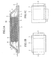
- a battery according to the present invention includes a battery enclosure 3, a power-generating unit 50 and positive and negative terminal electrodes 1, 2.
- the power-generating unit 50 is accommodated in the rectangular battery enclosure 3 formed of a composite laminate film.
- the positive terminal electrode 1 has a width substantially equal to a width of the positive electrode collector 5 of the power-generating unit 50.
- the negative terminal electrode 2 has a width substantially equal to a width of the negative electrode collector 7 of the power-generating unit 50.
- the positive and negative terminal electrodes 1 and 2 protrude from mutually different sides of the rectangular battery enclosure 3.
- the positive and negative electrode collectors 5, 7 are electrically connected to the positive and negative terminal electrodes 1, 2 in the battery enclosure 3, respectively.
- the positive and negative terminal electrodes 1, 2 are formed so as to protrude from the battery enclosure 3 by stacking the respective end portions of the positive and negative electrode collectors 5, 7.
- the power-generating unit 50 is configured by stacking the positive electrodes 4, the negative electrodes 6 and separators 8. Each of the separators 8 is located between each of the positive electrodes 4 and each of the negative electrodes 6.
- the power-generating unit 50 is hermetically sealed by the battery enclosure 3 composed of a laminate film compounded of polymer and metal.
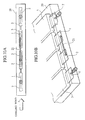
- FIG. 1A shows the internal structure of the battery.
- the end portions of the collectors 5 of the respective positive electrodes 4 are extended together from one sides of the separators 8 to the left in the drawing and are protruded from the battery enclosure 3 in a stacked state, and thus a positive terminal electrode 1 is formed.
- the end portions of the collectors 7 of the respective negative electrodes 6 are extended together from the other sides of the separators 8 to the right in the drawing and are protruded from the battery enclosure 3 in the stacked state, and thus a negative terminal electrode 2 is formed.
- the positive terminal electrode 1 formed of the plurality of positive electrode collectors 5 and the negative terminal electrode 2 formed of the plurality of negative electrode collectors 7 are not only protruded from two opposite sides of the rectangular battery enclosure 3 as described above (refer to FIG. 1B), respectively, but also may be protruded from two adjacent sides thereof as shown in FIG. 1C, respectively.
- the collectors 5 and 7 of the stacked positive and negative electrodes may be connected to current-drawing terminal electrodes 9 and 10 in the inside of the battery enclosure, respectively.
- the current-drawing terminal electrodes 9 and 10 have a width approximately equal to that of the collectors 5 and 7, respectively. It is also possible to form the positive and negative terminal electrodes 1 and 2 by protruding these terminal electrodes 9 and 10 from the battery enclosure 3.
- the stacked electrode collectors directly function as the terminal electrodes.
- the wide current-drawing terminal electrodes attached to the collectors in the battery enclosure are directly protruded therefrom. Therefore, the heating of the terminal portions can be sufficiently controlled in the case of drawing a large current.
- the batteries can be mutually connected relatively simply by use of means such as, for example, ultrasonic welding, without using bolts and the like conventionally. Thus, a sufficient welding area is secured, thereby lowering the resistance of the entire assembled battery and achieving the lightweight thereof.
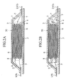
- each of the positive and negative electrode collectors 5, 7 includes at least one collector thicker than the other collectors. Namely, as shown in FIG. 2B, thickness of one collector T52 of the positive electrode collectors 5 is larger than that of the other collectors T51 of the positive electrode collectors 5. Similarly, thickness of one collector T72 of the negative electrode collectors 7 is larger than that of the other collectors T71 of the negative electrode collectors 7.
- Another structure can be adopted, in which such thick collectors 5,7 function as the positive and negative terminal electrodes, and protrude from the battery enclosure 3. The other positive and negative collectors 5, 7 are electrically connected to such thick collectors 5, 7 for the terminal electrodes (see FIG. 2B).
- the heating of the terminal portions in the case of drawing a large current is controlled. Further, the strength of the battery is increased by the rigidity of the thick collectors 5, 7, and even if some force is applied to the battery from the outside due to some reasons, the shape of the battery is maintained.
- the material of the terminal electrodes 1, 2 be composed of a three-dimensional deformable metal.
- the three-dimensional deformable metal is used for the faces of the positive and negative terminal electrodes 1 and 2, which are defined by the length direction of the battery (same direction as the direction of drawing the terminal electrodes 1 and 2), the width direction thereof (direction perpendicular to the direction of drawing the terminal electrodes 1 and 2) or the direction including both of the length and width directions. Therefore, the angles and the like of the terminal electrodes 1 and 2 can be freely changed. Accordingly, it becomes possible to adjust the amount and direction of the cooling wind, and thus the cooling effect is improved.
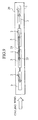
- FIGS. 3A and 3B show structures of batteries, in which the protruding portions of the positive and negative terminal electrodes 1 and 2 are subjected to twist deformation around center axes of directions in which the terminal electrodes 1, 2 protrude.
- the angles are applied to the terminal electrodes 1 and 2 as described above, and thus the cooling wind sent to the terminal electrode portions is rectified to the directions of the upper and lower faces of each battery.
- warmed air can be diverted to the directions described above. Therefore, the cooling effect is improved, and the lifetime of the battery is improved.
- structures can also be adopted, in which the one-side end portions in the width directions of the positive and negative terminal electrodes 1 and 2 protruding from the battery enclosure 3 are deformed to the directions of the upper and lower faces of the battery.
- the cooling wind is rectified similarly, the cooling effect is enhanced, and the lifetime of the battery is improved.
- structures can also be adopted, in which the tip portions of the protruding portions of the positive and negative electrodes 1 and 2 are deformed to the directions of the upper and lower faces of the battery.
- the cooling effect is enhanced similarly to the above-described batteries, and the lifetime of the battery is improved.
- structures can also be adopted, in which the protruding portions of the positive and negative electrodes 1 and 2, which protrude from the battery enclosure 3, are provided with waveform rugged portions in the length or width directions thereof. Swirling flows can be generated in the cooling wind by these waveform rugged portions. Thus, the cooling of the terminal electrode portions becomes even, and the temperature distribution becomes even. Accordingly, the lifetime of the battery is improved.
- the surface areas of the terminal electrodes 1 and 2 can be expanded more than flat terminals without increasing the mounting area of the battery, thereby enhancing the cooling effect for the terminal electrodes 1 and 2 and the entire battery.
- projections 11 may be formed on the front and/or back surface sides of the protruding portions of the positive and negative terminal electrodes 1 and 2. Swirling flows are generated in the cooling winds from the length and/or width directions of the battery similarly to the batteries shown in FIGS. 6A and 6B. Therefore, the terminal electrode portions are cooled evenly, and the temperature distribution becomes even, whereby the lifetime of the battery is improved.
- the positive and negative terminal electrodes 1 and 2 are selected from, for example, ones mainly containing Al, Cu, Ni, SUS (stainless steel), iron, gold and silver, considering required properties including strength, workability and nonreaction with a material used for the battery excluding battery reaction.
- the electrode material is not particularly limited to these.
- positive and negative electrodes capable of occluding/desorbing lithium ions may also be used for the electrodes of the battery.
- a positive electrode active material mainly composed of one selected from LiCoO 2 , LiMn 2 O 4 and LiNiO 2 for the positive electrode
- a negative electrode active material mainly composed of one selected from graphite and hard carbon for the negative electrode
- the active materials are not particularly limited to these materials.
- an electrolyte solution one obtained by impregnating a nonaqueous electrolyte solution into the separators, a solid electrolyte or a gel electrolyte, or a solid or gel electrolyte including the separators 8 may be used.
- the assembled battery is composed by using batteries in which terminal electrode portions are deformed and projections are provided thereon, thereby restricting the temperature increase of the assembled battery and improving the lifetime thereof.
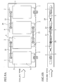
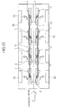
- FIGS. 8A and 8B show an assembled battery, in which a plurality of batteries shown in FIG. 3A, which are composed by subjecting the positive and negative terminal electrodes 1 and 2 to the twist deformation, are provided in an outer case 20, and these batteries are connected in series by inter-battery connection leads 21.
- the number of batteries is four.
- the batteries are arrayed such that the twist angles of the terminal electrodes 1 and 2 become larger from the windward toward leeward of the cooling wind for cooling the battery, which is indicated by arrows in the drawings.
- the temperature of the cooling wind is increased toward the leeward, and the assembled battery becomes more difficult to be cooled, whereby the temperature in the assembled battery becomes higher toward the leeward.
- the batteries are arrayed such that the twist angles of the terminal electrodes become larger toward the leeward, and thus areas in contact with the cooling wind can be increased toward the leeward. Further, it becomes possible to receive the cooling wind more effectively toward the leeward without providing any complicated rectification structure in the outer case 20. Moreover, the warmed cooling wind can be diverted to the directions of upper and lower faces of each battery. Therefore, the temperature distribution in the assembled battery becomes even, so that the endurance lifetime of the assembled battery is improved.
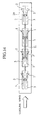
- FIG. 9 shows an assembled battery, in which a plurality of batteries shown in FIGS. 4A, which are composed by deforming the side edge portions of the positive and negative terminal electrodes 1 and 2 to the front surface side thereof, are provided in the outer case 20 similarly to FIGS. 8A and 8B, and are arrayed such that the deformation amounts of the ends of the electrodes to the upper direction are increased from the windward toward leeward of the cooling wind for the batteries.
- the amount of the cooling wind flowing on the battery surface is increased toward the leeward.
- areas in contact with the cooling wind are increased toward the leeward, such that a necessity of providing a complicated rectification structure in the outer case is eliminated. Accordingly, the temperature distribution in the assembled battery becomes even, and the lifetime of the assembled battery is improved.
- FIGS. 10A and 10B show an assembled battery, in which a plurality of batteries shown in FIG. 6A, which have waveform rugged portions formed in the positive and negative terminal electrodes 1 and 2, are provided in the outer case 20 similarly to FIG. 9, and are arrayed such that the amplitude amounts of the waveform rugged portions are increased from the windward toward leeward of the cooling wind for the batteries.
- a structure With such a structure, swirling flows becoming larger from the windward to the leeward are generated in the cooling wind.
- the cooling of the terminal electrode portions becomes even, thus eliminating the necessity of providing a complicated structure in the outer case similarly. Therefore, the temperature distribution in the assembled battery can be made even, and the lifetime of the assembled battery is improved.
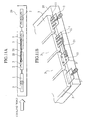
- FIGS. 11A and 11B show an assembled battery, in which batteries shown in FIG. 7A, which have the projections 11 formed in the protruding portions of the positive and negative terminal electrodes 1 and 2 from the battery enclosure 3, are provided in the outer case 20 similarly to FIGS. 10A and 10B, and are arrayed such that the number of projections 11 on the terminal electrodes is increased from the windward toward leeward of the cooling wind.
- the terminal electrodes 1 and 2 are cooled evenly, and a complicated rectification structure does not need to be used. Accordingly, the temperature distribution in the assembled battery is made even, and the lifetime of the assembled battery is improved.
- FIG. 12 shows an assembled battery, in which the batteries shown in FIG. 3A are used, and the angles of the terminal electrodes 1 and 2 are adjusted so as to rectify the cooling wind for the batteries to the battery control circuits 22 provided in the outer case 20.
- the temperature distribution of the control circuits 22 can also be made even, and the reliability of the control circuits 22 is improved.
- the assembled batteries in which the plurality of batteries equipped with the positive and negative terminal electrodes 1 and 2 composed of the material and formed in the shape as described above are provided in the case can be configured such that at least two sets thereof are provided each in the upper and lower directions or the right and left directions, further in the upper and lower directions and the right and left directions.
- the battery enclosure 3 was composed of a laminate film formed by sandwiching aluminum foil between nylon 6 and denatured PP (polypropylene).
- the positive electrode 4 was composed by using aluminum foil having a thickness of approximately 20 ⁇ m as the positive electrode collector 5 and by coating LiMn 2 O 4 as a positive electrode active material on the aluminum foil.
- the negative electrode 6 was composed by using copper foil having a thickness of approximately 10 ⁇ m as the negative electrode collector 7 and by coating hard carbon that is amorphous carbon as a negative electrode active material on the copper foil.
- the laminate film 3, the positive electrode 4, the negative electrode 6 and the separator 8 were stacked in order of the laminate film 3, the negative electrode 6, the separator 8 and the positive electrode 4.
- the positive electrode collector 5 and the negative electrode collector 7 were protruded by the width of 40 mm from the mutually opposite positions of the separator 8 having a rectangular shape.
- An aluminum-made positive terminal electrode 9 having a thickness of approximately 200 ⁇ m, a width of approximately 40 mm and a length of 30 mm was welded to the positive electrode collector 5.
- a nickel-made negative terminal electrode 10 having the same dimension as the aluminum-made positive terminal electrode 9 was welded to the negative electrode collector 7.
- These positive terminal electrode 9 and negative terminal electrode 10 were sandwiched by the laminate film as the battery enclosure 3.
- the positive and negative terminal electrodes 1 and 2 were composed of portions in which the positive and negative terminal electrodes 9 and 10 are protruded from the battery enclosure 3 by the length of approximately 20 mm.
- the peripheral portions of the positive and negative terminal electrodes 1 and 2 were heated and welded together, and the entire body was sealed, thereby fabricating a battery whose capacity is approximately 2 Ah.
- the positive and negative terminal electrodes 1 and 2 were protruded from two sides of a battery enclosure 3, which are adjacent to each other, and thus the positive and negative terminal electrodes 1 and 2 were protruded from the laminate film of the battery enclosure 3 so as to make an angle of 90° (refer to FIG. 1C).
- the battery was fabricated similarly to the above-described Example 1 besides the above.
- a battery was fabricated similarly to Example 1. As shown in FIG. 3A, the positive and negative terminal electrodes 1 and 2 were subjected to twist deformation, and a structure was made, in which the positive and negative terminal electrodes 1 and 2 have angles equal to each other with respect to the plane direction of the battery.
- a battery was fabricated similarly to Example 1. As shown in FIG. 3B, the positive and negative terminal electrodes 1 and 2 were subjected to twist deformation, and a structure was made, in which the positive and negative terminal electrodes 1 and 2 have angles reverse to each other with respect to the plane direction of the battery.
- a battery was fabricated similarly to Example 1. As shown in FIG. 4A, a structure was made, in which the one-side ends of the terminal electrodes 1 and 2 in the width direction were deformed to the upper direction of the battery.
- a battery was fabricated similarly to Example 1. As shown in FIG. 4B, a structure was made, in which the one-side ends of the terminal electrodes 1 and 2 in the width direction were deformed to the lower direction of the battery.
- a battery was fabricated similarly to Example 1. As shown in FIG. 4C, a structure was made, in which the one-side ends of the terminal electrodes 1 and 2 in the width direction were deformed to directions different from each other, that is, the upper and lower directions of the battery, respectively.
- a battery was fabricated similarly to Example 1. As shown in FIG. 5A, a structure was made, in which the tip portions of the terminal electrodes 1 and 2 were deformed to the upper direction of the battery.
- a battery was fabricated similarly to Example 1. As shown in FIG. 5B, a structure was made, in which the tip portions of the terminal electrodes 1 and 2 were deformed to the lower direction of the battery.
- a battery was fabricated similarly to Example 1. As shown in FIG. 5C, a structure was made, in which the tip portions of the terminal electrodes 1 and 2 were deformed to directions different from each other, that is, the upper and lower directions of the battery, respectively.
- a battery was fabricated similarly to Example 1. As shown in FIG. 6A, a structure was made, in which waveform rugged portions having a cycle between peaks of 5 mm are formed on the terminal electrodes 1 and 2 in the length direction of the battery.
- a battery was fabricated similarly to Example 1. As shown in FIG. 6B, a structure was made, in which waveform rugged portions having a cycle between peaks of 9 mm are formed in the terminal electrodes 1 and 2 in the width direction of the battery.
- a battery was fabricated similarly to Example 1. As shown in FIG. 7A, projections having convex portions on the upper face of the battery were formed on the terminal electrodes 1 and 2.
- a battery was fabricated similarly to Example 1. As shown in FIG. 7B, projections having convex portions on the lower face of the battery were formed on the terminal electrodes 1 and 2.
- Batteries were fabricated similarly to Example 3, and the positive and negative terminal electrodes 1 and 2 were subjected to twist deformation. As shown in FIGS. 8A and 8B, the batteries were arranged in the outer case 20 in a state where the respective terminal electrodes 1 and 2 were deformed at angles of 0°, 10°, 20° and 30° with respect to the level surface from the windward of the cooling wind at the left side in the drawing, and thus an assembled battery was configured.
- lead wires having a diameter of 8 mm were used as the inter-battery connection leads 21, and the terminals of the batteries, which are adjacent to each other, were connected in series by screws 23.
- Batteries were fabricated similarly to Example 5, and as shown in FIG. 9, the batteries were arrayed in the outer case 20 so as to get along with the flowing direction of the cooling wind. Moreover, the single batteries were mutually connected in series through the inter-battery connection leads 21, and thus an assembled battery was fabricated.
- Batteries were fabricated similarly to Example 11.
- the batteries were arranged in the outer case 20 such that the amplitudes of the waveform rugged portions formed on the positive and negative terminal electrodes 1 and 2 were 0, 1, 2 and 4 mm from the windward of the cooling wind. Further, the respective single batteries were mutually connected in series by the connection leads 21, and thus an assembled battery as shown in FIGS. 10A and 10B was obtained.
- Batteries were fabricated similarly to Example 13.
- the batteries were arranged in the outer case 20 such that the numbers of projections 11 formed on the positive and negative terminal electrodes 1 and 2 were 0, 5, 8 and 9 from the windward.
- the respective single batteries were connected in series by the connection leads 21, and thus an assembled battery as shown in FIGS. 11A and 11B was obtained.
- Batteries fabricated similarly to Example 3 were arranged in four columns and two steps in the outer case 20.
- the respective positive and negative terminal electrodes 1 and 2 were deformed at an angle of 20° with respect to the level surface so as to be capable of rectifying the cooling wind toward the control circuits 22.
- a structure was made, in which not only the batteries but also the control circuits 22 can be cooled by the cooling wind, and thus an assembled battery as shown in FIG. 12 was obtained.
- the battery enclosure 3, the negative electrodes 6, the separators 8 and the positive electrodes 4 were stacked in this order by use of the positive electrodes 4, the negative electrodes 6 and the separators 8, which were similar to those of the above-described Example 1.
- the positive and negative electrode collectors 5 and 7 were protruded by the width of 10 mm from the opposite positions of the separators 8.
- a Ni-made electrode terminal having a thickness of approximately 200 ⁇ m, a width of approximately 10 mm and a length of 30 mm was welded to the positive electrode collectors 5.
- a Cu-made electrode terminal having the same dimension as the Ni-made electrode terminal was welded to the negative electrode collectors 7.
- the Ni-made and Cu-made electrode terminals were protruded from the battery enclosure 3 by the length of approximately 20 mm, and were made as the positive and negative terminal electrodes 1 and 2, respectively.
- the peripheral portions of these positive and negative terminal electrodes 1 and 2 were heated and welded together, and the entire body was sealed, thereby fabricating a battery whose capacity is approximately 2 Ah.
- Example 14 the temperature increases in the case of carrying out the discharge of the electric power at the current of 40A that is equivalent to the current flowing at 20°C for five seconds for the batteries of Examples 1 to 14 and Comparative Example were measured.
- the following table shows results thereof.
- Classification Temperature Increase of Terminal Electrodes ⁇ T (°C) Comparative Example 69 Example 1 18 Example 2 18 Example 3 16 Example 4 17 Example 5 16 Example 6 16 Example 7 15 Example 8 16 Example 9 17 Example 10 14 Example 11 15 Example 12 14 Example 13 15 Example 14 15
- the terminal electrodes are deformed and imparted with the rectification effect for the cooling wind, whereby the temperature increase of the terminal electrodes can be controlled, and the lifetime of the battery can be improved.
- the temperature increase at the terminal electrodes can be sufficiently controlled by directly protruding the wide terminal electrodes from the battery enclosure.
- the terminal electrodes directly protruded from the battery enclosure are composed of metal that is three-dimensional deformable in the length and/or width directions of the battery, and the cooling wind is rectified by deforming the terminal electrodes in appropriate directions and providing wave rugged portions or projections. In this way, the temperature increases of the terminal electrodes and the battery body can be controlled, thus bringing an extremely excellent effect that the lifetime of the battery can be improved significantly.
Applications Claiming Priority (2)
| Application Number | Priority Date | Filing Date | Title |
|---|---|---|---|
| JP2001379881A JP3755591B2 (ja) | 2001-12-13 | 2001-12-13 | 電池およびそれを用いた組電池 |
| JP2001379881 | 2001-12-13 |
Publications (3)
| Publication Number | Publication Date |
|---|---|
| EP1326294A2 true EP1326294A2 (de) | 2003-07-09 |
| EP1326294A3 EP1326294A3 (de) | 2006-07-12 |
| EP1326294B1 EP1326294B1 (de) | 2012-08-22 |
Family
ID=19187013
Family Applications (1)
| Application Number | Title | Priority Date | Filing Date |
|---|---|---|---|
| EP20020024214 Expired - Lifetime EP1326294B1 (de) | 2001-12-13 | 2002-10-30 | Batterie und ihre Verwendung in einer zusammengesetzte Batterie |
Country Status (3)
| Country | Link |
|---|---|
| US (1) | US7501203B2 (de) |
| EP (1) | EP1326294B1 (de) |
| JP (1) | JP3755591B2 (de) |
Cited By (2)
| Publication number | Priority date | Publication date | Assignee | Title |
|---|---|---|---|---|
| US8911894B2 (en) | 2006-07-19 | 2014-12-16 | Toyota Jidosha Kabushiki Kaisha | Battery assembly |
| EP1333520B1 (de) * | 2002-02-01 | 2018-08-29 | NEC Corporation | Flachzelle und deren Verwendung in einer kombinierten Batterie |
Families Citing this family (33)
| Publication number | Priority date | Publication date | Assignee | Title |
|---|---|---|---|---|
| JP4593056B2 (ja) * | 2002-05-07 | 2010-12-08 | 富士重工業株式会社 | 板状電池の接続構造 |
| JP3698320B2 (ja) * | 2002-06-03 | 2005-09-21 | 日産自動車株式会社 | 組電池 |
| KR100727201B1 (ko) * | 2003-07-31 | 2007-06-13 | 닛본 덴끼 가부시끼가이샤 | 리튬 이온 2차 전지 |
| JP5240963B2 (ja) * | 2003-10-01 | 2013-07-17 | 日産自動車株式会社 | 組電池 |
| JP4747487B2 (ja) * | 2003-10-10 | 2011-08-17 | 日産自動車株式会社 | 単電池および電圧検出用の端子の形成方法 |
| JP4894129B2 (ja) * | 2003-10-10 | 2012-03-14 | 日産自動車株式会社 | 薄型電池及び組電池 |
| JP4899299B2 (ja) * | 2003-10-14 | 2012-03-21 | 日産自動車株式会社 | 薄型電池 |
| US8227116B2 (en) * | 2003-12-15 | 2012-07-24 | Nec Corporation | Secondary battery |
| JP4449907B2 (ja) * | 2003-12-15 | 2010-04-14 | 日本電気株式会社 | 二次電池用電解液およびそれを用いた二次電池 |
| JP4617672B2 (ja) * | 2003-12-26 | 2011-01-26 | トヨタ自動車株式会社 | ラミネート電池モジュールとその製造方法 |
| JP4590869B2 (ja) * | 2004-01-14 | 2010-12-01 | トヨタ自動車株式会社 | ラミネート型二次電池 |
| JP2006196428A (ja) * | 2004-05-31 | 2006-07-27 | Nissan Motor Co Ltd | 組電池およびその製造方法 |
| US20060172202A1 (en) * | 2005-02-03 | 2006-08-03 | Smith W N | Low temperature electrolytes and cell construction for low temperature lithium rechargeable batteries |
| JP2006269333A (ja) * | 2005-03-25 | 2006-10-05 | Nissan Motor Co Ltd | 燃料電池 |
| JP4532448B2 (ja) * | 2005-10-26 | 2010-08-25 | パナソニックEvエナジー株式会社 | 角形電池用電極ユニット、角形電池および角形電池用電極ユニットの製造方法 |
| JP4839955B2 (ja) * | 2006-05-11 | 2011-12-21 | トヨタ自動車株式会社 | 電池パックおよび車両 |
| JP4462245B2 (ja) * | 2006-07-19 | 2010-05-12 | トヨタ自動車株式会社 | 2次電池、積層2次電池および組電池 |
| DE102008038936A1 (de) * | 2008-08-13 | 2010-02-25 | Behr Gmbh & Co. Kg | Galvanisches Element |
| DE102009006117A1 (de) * | 2009-01-26 | 2010-07-29 | Li-Tec Battery Gmbh | Elektrochemische Energiespeicherzelle |
| JP4784687B2 (ja) * | 2009-10-09 | 2011-10-05 | 日本電気株式会社 | 扁平型電池およびそれを用いた組電池 |
| US20110177383A1 (en) * | 2010-01-19 | 2011-07-21 | Lightening Energy | Battery cell module for modular battery with interleaving separator |
| DE102010012934A1 (de) * | 2010-03-26 | 2011-09-29 | Daimler Ag | Einzelzelle und Batterie mit einer Mehrzahl von Einzelzellen |
| JP5589534B2 (ja) * | 2010-04-28 | 2014-09-17 | 日産自動車株式会社 | 扁平型電池 |
| US20120052365A1 (en) * | 2010-08-27 | 2012-03-01 | Chun-Chieh Chang | Advanced high durability lithium-ion battery |
| JP5625899B2 (ja) * | 2010-12-28 | 2014-11-19 | 株式会社豊田自動織機 | 電池 |
| JP2013033688A (ja) * | 2011-08-03 | 2013-02-14 | Sharp Corp | 二次電池 |
| CN103748725B (zh) * | 2011-08-23 | 2016-03-23 | 丰田自动车株式会社 | 蓄电装置和蓄电装置的制造方法 |
| JP6186209B2 (ja) * | 2013-08-23 | 2017-08-23 | 昭和電工株式会社 | 組電池の冷却兼加熱構造 |
| JP6075250B2 (ja) * | 2013-09-10 | 2017-02-08 | トヨタ自動車株式会社 | 蓄電装置の温度調節構造及び温度調節方法 |
| DE102015202338A1 (de) * | 2015-02-10 | 2016-08-11 | Robert Bosch Gmbh | Design für Feststoffzellen |
| GB2555649B (en) * | 2016-11-08 | 2021-03-10 | Oxis Energy Ltd | Battery |
| CN111656569B (zh) * | 2018-01-30 | 2023-08-29 | 株式会社Aesc日本 | 电池单元以及电池组 |
| JP7359682B2 (ja) | 2019-12-20 | 2023-10-11 | ファナック株式会社 | バスバーを有するモータ駆動装置 |
Citations (2)
| Publication number | Priority date | Publication date | Assignee | Title |
|---|---|---|---|---|
| US5871861A (en) * | 1994-04-05 | 1999-02-16 | Mitsubishi Chemical Corporation | Lithium ion secondary cell |
| JP2001143769A (ja) * | 1999-11-18 | 2001-05-25 | Hitachi Ltd | 電池モジュール及び電力供給装置 |
Family Cites Families (28)
| Publication number | Priority date | Publication date | Assignee | Title |
|---|---|---|---|---|
| US3220888A (en) * | 1962-09-20 | 1965-11-30 | Welch Allyn Inc | Rechargeable battery pack |
| US3506902A (en) * | 1967-07-27 | 1970-04-14 | Mallory & Co Inc P R | Rechargeable cells and connection means therefor |
| GB1318969A (en) * | 1969-10-02 | 1973-05-31 | Chloride Batteries Au Ltd | Battery intercell connector |
| GB1422782A (en) * | 1972-04-06 | 1976-01-28 | Alkaline Batteries Ltd | Alkaline electric cells |
| US3930889A (en) * | 1974-07-22 | 1976-01-06 | Bell & Howell Company | Multiple source battery-powered apparatus |
| US3969143A (en) * | 1975-07-22 | 1976-07-13 | Wilson Greatbatch Ltd. | Enclosure for lithium-iodine cell and method of making the same |
| JPH03241669A (ja) * | 1990-02-20 | 1991-10-28 | Yuasa Battery Co Ltd | 非水溶液電池とその集合電池 |
| US5283137A (en) * | 1991-04-29 | 1994-02-01 | Optima Batteries, Inc. | Cover assembly for rechargeable battery |
| JPH05166500A (ja) * | 1991-12-13 | 1993-07-02 | Yuasa Corp | 積層薄形電池 |
| US5587253A (en) * | 1993-03-05 | 1996-12-24 | Bell Communications Research, Inc. | Low resistance rechargeable lithium-ion battery |
| US5532080A (en) * | 1993-07-02 | 1996-07-02 | Konica Corporation | Cylindrical type dry battery and battery chamber |
| JPH0896841A (ja) * | 1994-09-22 | 1996-04-12 | Mitsubishi Chem Corp | リチウムイオン二次電池 |
| DK175086B1 (da) * | 1995-07-07 | 2004-05-24 | Danionics As | Viklet elektrokemisk celle, fremgangsmåde til fremstilling heraf og anvendelse af en sådan elektrokemisk celle |
| JPH11185719A (ja) * | 1997-12-25 | 1999-07-09 | Rohm Co Ltd | 電気部品の保護ケース、および充電池パック |
| WO2000035035A1 (en) * | 1998-12-04 | 2000-06-15 | Matsushita Electric Industrial Co., Ltd. | Battery and battery holder |
| JP3114719B2 (ja) * | 1999-02-02 | 2000-12-04 | 日本電気株式会社 | 積層型電池 |
| JP2000348772A (ja) * | 1999-06-04 | 2000-12-15 | Japan Storage Battery Co Ltd | 非水電解質電池 |
| US6617074B1 (en) * | 1999-06-30 | 2003-09-09 | Mitsubishi Materials Corporation | Lithium ion polymer secondary battery and gelatinous polymer electrolyte for sheet battery |
| JP2001085016A (ja) * | 1999-09-09 | 2001-03-30 | Sony Corp | 非水電解質電池 |
| JP2001160389A (ja) * | 1999-12-01 | 2001-06-12 | Toshiba Battery Co Ltd | リード折り曲げ装置 |
| US6413668B1 (en) * | 2000-01-10 | 2002-07-02 | Delphi Technologies, Inc. | Lithium ion battery and container |
| KR100515571B1 (ko) * | 2000-02-08 | 2005-09-20 | 주식회사 엘지화학 | 중첩 전기 화학 셀 |
| US6406815B1 (en) * | 2000-02-11 | 2002-06-18 | Delphi Technologies, Inc. | Compact lithium ion battery and method of manufacturing |
| JP2002075310A (ja) * | 2000-08-23 | 2002-03-15 | Nintendo Co Ltd | 蓄電池の逆差し防止構造およびそれに用いられる蓄電池と電池収納部 |
| JP3680744B2 (ja) * | 2001-02-23 | 2005-08-10 | 三菱マテリアル株式会社 | リチウムイオンポリマー二次電池 |
| US6849358B2 (en) * | 2001-04-06 | 2005-02-01 | Ngk Spark Plug Co., Ltd. | Lithium ion battery |
| JP4720065B2 (ja) * | 2001-09-04 | 2011-07-13 | 日本電気株式会社 | フィルム外装電池及び組電池 |
| US6897634B2 (en) * | 2002-04-13 | 2005-05-24 | Motorola, Inc. | Rechargeable battery having charging indicating means |
-
2001
- 2001-12-13 JP JP2001379881A patent/JP3755591B2/ja not_active Expired - Lifetime
-
2002
- 2002-10-30 EP EP20020024214 patent/EP1326294B1/de not_active Expired - Lifetime
- 2002-12-11 US US10/316,084 patent/US7501203B2/en not_active Expired - Lifetime
Patent Citations (2)
| Publication number | Priority date | Publication date | Assignee | Title |
|---|---|---|---|---|
| US5871861A (en) * | 1994-04-05 | 1999-02-16 | Mitsubishi Chemical Corporation | Lithium ion secondary cell |
| JP2001143769A (ja) * | 1999-11-18 | 2001-05-25 | Hitachi Ltd | 電池モジュール及び電力供給装置 |
Non-Patent Citations (4)
| Title |
|---|
| PATENT ABSTRACTS OF JAPAN vol. 016, no. 027 (E-1158), 23 January 1992 (1992-01-23) & JP 03 241669 A (YUASA BATTERY CO LTD), 28 October 1991 (1991-10-28) * |
| PATENT ABSTRACTS OF JAPAN vol. 017, no. 566 (E-1446), 13 October 1993 (1993-10-13) & JP 05 166500 A (YUASA CORP), 2 July 1993 (1993-07-02) * |
| PATENT ABSTRACTS OF JAPAN vol. 1996, no. 08, 30 August 1996 (1996-08-30) & JP 08 096841 A (MITSUBISHI CHEM CORP), 12 April 1996 (1996-04-12) * |
| PATENT ABSTRACTS OF JAPAN vol. 2000, no. 15, 6 April 2001 (2001-04-06) & JP 2000 348772 A (JAPAN STORAGE BATTERY CO LTD), 15 December 2000 (2000-12-15) * |
Cited By (2)
| Publication number | Priority date | Publication date | Assignee | Title |
|---|---|---|---|---|
| EP1333520B1 (de) * | 2002-02-01 | 2018-08-29 | NEC Corporation | Flachzelle und deren Verwendung in einer kombinierten Batterie |
| US8911894B2 (en) | 2006-07-19 | 2014-12-16 | Toyota Jidosha Kabushiki Kaisha | Battery assembly |
Also Published As
| Publication number | Publication date |
|---|---|
| US7501203B2 (en) | 2009-03-10 |
| JP3755591B2 (ja) | 2006-03-15 |
| US20030113621A1 (en) | 2003-06-19 |
| JP2003187857A (ja) | 2003-07-04 |
| EP1326294A3 (de) | 2006-07-12 |
| EP1326294B1 (de) | 2012-08-22 |
Similar Documents
| Publication | Publication Date | Title |
|---|---|---|
| US7501203B2 (en) | Battery formed of a stack of substantially rectangular electrodes | |
| JP4323465B2 (ja) | 二次電池 | |
| KR100637443B1 (ko) | 이차 전지와 이에 사용되는 단자 조립체 | |
| US8765291B2 (en) | Rechargeable battery | |
| US7393610B2 (en) | Laminate packaging flat cell | |
| JP5070703B2 (ja) | 双極型電池 | |
| JP2006012836A (ja) | 二次電池 | |
| JP4655593B2 (ja) | バイポーラ電池 | |
| JP2007213990A (ja) | 電池モジュール、組電池及びそれらの電池を搭載した車両 | |
| KR20160087220A (ko) | 이차전지 및 이차전지 배열 | |
| JP2004139775A (ja) | 積層型電池、組電池および車両 | |
| CN210805919U (zh) | 二次电池及其电极构件、电池模块和使用二次电池的装置 | |
| JP2004134210A (ja) | 積層型電池、組電池および車両 | |
| KR100627360B1 (ko) | 집전판용 플레이트와 이의 이차 전지 및 전지 모듈 | |
| US11855304B2 (en) | Secondary battery | |
| KR20050121914A (ko) | 이차 전지와 이에 사용되는 전극 조립체 | |
| JP2008311173A (ja) | 蓄電装置 | |
| JP2012134016A (ja) | 電圧検知用端子、端子付プレートおよび電池モジュール | |
| KR20080047165A (ko) | 전극 조립체 및 이를 구비하는 이차전지 | |
| US20140023913A1 (en) | Prismatic secondary battery | |
| JP2010525552A (ja) | 溶接点接続部を持つ電気化学単電池及びエネルギー貯蔵装置 | |
| KR100612236B1 (ko) | 이차 전지와 이에 사용되는 전극 조립체 | |
| JP4929587B2 (ja) | バイポーラ電池およびその製造方法、組電池 | |
| CN109659622A (zh) | 蓄电元件及蓄电元件的制造方法 | |
| CN111293268B (zh) | 电池 |
Legal Events
| Date | Code | Title | Description |
|---|---|---|---|
| PUAI | Public reference made under article 153(3) epc to a published international application that has entered the european phase |
Free format text: ORIGINAL CODE: 0009012 |
|
| 17P | Request for examination filed |
Effective date: 20021030 |
|
| AK | Designated contracting states |
Designated state(s): AT BE BG CH CY CZ DE DK EE ES FI FR GB GR IE IT LI LU MC NL PT SE SK TR |
|
| AX | Request for extension of the european patent |
Extension state: AL LT LV MK RO SI |
|
| PUAL | Search report despatched |
Free format text: ORIGINAL CODE: 0009013 |
|
| AK | Designated contracting states |
Kind code of ref document: A3 Designated state(s): AT BE BG CH CY CZ DE DK EE ES FI FR GB GR IE IT LI LU MC NL PT SE SK TR |
|
| AX | Request for extension of the european patent |
Extension state: AL LT LV MK RO SI |
|
| RIC1 | Information provided on ipc code assigned before grant |
Ipc: H01M 10/50 20060101ALI20060602BHEP Ipc: H01M 10/04 20060101ALI20060602BHEP Ipc: H01M 2/30 20060101ALI20060602BHEP Ipc: H01M 2/06 20060101ALI20060602BHEP Ipc: H01M 2/20 20060101AFI20030520BHEP Ipc: H01M 2/26 20060101ALI20060602BHEP |
|
| AKX | Designation fees paid |
Designated state(s): DE FR GB |
|
| 17Q | First examination report despatched |
Effective date: 20071115 |
|
| REG | Reference to a national code |
Ref country code: DE Ref legal event code: R079 Ref document number: 60243546 Country of ref document: DE Free format text: PREVIOUS MAIN CLASS: H01M0002200000 Ipc: H01M0002020000 |
|
| GRAP | Despatch of communication of intention to grant a patent |
Free format text: ORIGINAL CODE: EPIDOSNIGR1 |
|
| RIC1 | Information provided on ipc code assigned before grant |
Ipc: H01M 10/04 20060101ALI20120322BHEP Ipc: H01M 10/50 20060101ALI20120322BHEP Ipc: H01M 2/02 20060101AFI20120322BHEP Ipc: H01M 4/70 20060101ALN20120322BHEP Ipc: H01M 6/42 20060101ALI20120322BHEP Ipc: H01M 2/20 20060101ALI20120322BHEP Ipc: H01M 2/30 20060101ALI20120322BHEP |
|
| RIN1 | Information on inventor provided before grant (corrected) |
Inventor name: HORIE, HIDEAKI Inventor name: SHIMAMURA, OSAMU Inventor name: ABE, TAKAAKI Inventor name: WATANABE, KYOICHI Inventor name: TANJOU, YUUJI |
|
| GRAS | Grant fee paid |
Free format text: ORIGINAL CODE: EPIDOSNIGR3 |
|
| GRAA | (expected) grant |
Free format text: ORIGINAL CODE: 0009210 |
|
| AK | Designated contracting states |
Kind code of ref document: B1 Designated state(s): DE FR GB |
|
| REG | Reference to a national code |
Ref country code: GB Ref legal event code: FG4D |
|
| REG | Reference to a national code |
Ref country code: DE Ref legal event code: R096 Ref document number: 60243546 Country of ref document: DE Effective date: 20121018 |
|
| PLBE | No opposition filed within time limit |
Free format text: ORIGINAL CODE: 0009261 |
|
| STAA | Information on the status of an ep patent application or granted ep patent |
Free format text: STATUS: NO OPPOSITION FILED WITHIN TIME LIMIT |
|
| 26N | No opposition filed |
Effective date: 20130523 |
|
| REG | Reference to a national code |
Ref country code: DE Ref legal event code: R097 Ref document number: 60243546 Country of ref document: DE Effective date: 20130523 |
|
| REG | Reference to a national code |
Ref country code: FR Ref legal event code: PLFP Year of fee payment: 15 |
|
| REG | Reference to a national code |
Ref country code: FR Ref legal event code: PLFP Year of fee payment: 16 |
|
| REG | Reference to a national code |
Ref country code: FR Ref legal event code: PLFP Year of fee payment: 17 |
|
| REG | Reference to a national code |
Ref country code: DE Ref legal event code: R082 Ref document number: 60243546 Country of ref document: DE Representative=s name: HOEFER & PARTNER PATENTANWAELTE MBB, DE Ref country code: DE Ref legal event code: R081 Ref document number: 60243546 Country of ref document: DE Owner name: ENVISION AESC JAPAN LTD., ZAMA-SHI, JP Free format text: FORMER OWNER: NISSAN MOTOR CO., LTD., YOKOHAMA-SHI, KANAGAWA-KEN, JP |
|
| REG | Reference to a national code |
Ref country code: DE Ref legal event code: R079 Ref document number: 60243546 Country of ref document: DE Free format text: PREVIOUS MAIN CLASS: H01M0002020000 Ipc: H01M0050100000 |
|
| PGFP | Annual fee paid to national office [announced via postgrant information from national office to epo] |
Ref country code: FR Payment date: 20210913 Year of fee payment: 20 |
|
| PGFP | Annual fee paid to national office [announced via postgrant information from national office to epo] |
Ref country code: GB Payment date: 20210922 Year of fee payment: 20 |
|
| PGFP | Annual fee paid to national office [announced via postgrant information from national office to epo] |
Ref country code: DE Payment date: 20210923 Year of fee payment: 20 |
|
| REG | Reference to a national code |
Ref country code: DE Ref legal event code: R071 Ref document number: 60243546 Country of ref document: DE |
|
| REG | Reference to a national code |
Ref country code: GB Ref legal event code: PE20 Expiry date: 20221029 |
|
| PG25 | Lapsed in a contracting state [announced via postgrant information from national office to epo] |
Ref country code: GB Free format text: LAPSE BECAUSE OF EXPIRATION OF PROTECTION Effective date: 20221029 |