EP1325307B1 - Optoakustische messanordnung und deren verwendung - Google Patents
Optoakustische messanordnung und deren verwendung Download PDFInfo
- Publication number
- EP1325307B1 EP1325307B1 EP01969117A EP01969117A EP1325307B1 EP 1325307 B1 EP1325307 B1 EP 1325307B1 EP 01969117 A EP01969117 A EP 01969117A EP 01969117 A EP01969117 A EP 01969117A EP 1325307 B1 EP1325307 B1 EP 1325307B1
- Authority
- EP
- European Patent Office
- Prior art keywords
- measuring
- radiation
- cell
- measuring cell
- radiation source
- Prior art date
- Legal status (The legal status is an assumption and is not a legal conclusion. Google has not performed a legal analysis and makes no representation as to the accuracy of the status listed.)
- Expired - Lifetime
Links
- 230000005855 radiation Effects 0.000 claims abstract description 85
- 239000000443 aerosol Substances 0.000 claims abstract description 45
- 239000000779 smoke Substances 0.000 claims abstract description 22
- 239000000126 substance Substances 0.000 claims abstract description 16
- 238000010895 photoacoustic effect Methods 0.000 claims abstract description 11
- 238000011156 evaluation Methods 0.000 claims abstract description 5
- 230000002745 absorbent Effects 0.000 claims abstract 5
- 239000002250 absorbent Substances 0.000 claims abstract 5
- 239000007789 gas Substances 0.000 claims description 49
- 238000001514 detection method Methods 0.000 claims description 15
- CSCPPACGZOOCGX-UHFFFAOYSA-N Acetone Chemical compound CC(C)=O CSCPPACGZOOCGX-UHFFFAOYSA-N 0.000 claims description 6
- RTZKZFJDLAIYFH-UHFFFAOYSA-N Diethyl ether Chemical compound CCOCC RTZKZFJDLAIYFH-UHFFFAOYSA-N 0.000 claims description 6
- LFQSCWFLJHTTHZ-UHFFFAOYSA-N Ethanol Chemical compound CCO LFQSCWFLJHTTHZ-UHFFFAOYSA-N 0.000 claims description 6
- OKKJLVBELUTLKV-UHFFFAOYSA-N Methanol Chemical compound OC OKKJLVBELUTLKV-UHFFFAOYSA-N 0.000 claims description 6
- 239000002360 explosive Substances 0.000 claims description 6
- 150000001875 compounds Chemical class 0.000 claims description 5
- 238000012544 monitoring process Methods 0.000 claims description 5
- BDERNNFJNOPAEC-UHFFFAOYSA-N propan-1-ol Chemical compound CCCO BDERNNFJNOPAEC-UHFFFAOYSA-N 0.000 claims description 4
- 239000003440 toxic substance Substances 0.000 claims description 4
- RWSOTUBLDIXVET-UHFFFAOYSA-N Dihydrogen sulfide Chemical compound S RWSOTUBLDIXVET-UHFFFAOYSA-N 0.000 claims description 3
- 150000001408 amides Chemical class 0.000 claims description 3
- 150000001412 amines Chemical class 0.000 claims description 3
- 229930195733 hydrocarbon Natural products 0.000 claims description 3
- 150000002430 hydrocarbons Chemical class 0.000 claims description 3
- LELOWRISYMNNSU-UHFFFAOYSA-N hydrogen cyanide Chemical compound N#C LELOWRISYMNNSU-UHFFFAOYSA-N 0.000 claims description 3
- -1 C4H10 Chemical compound 0.000 claims description 2
- 150000001298 alcohols Chemical class 0.000 claims description 2
- 150000001299 aldehydes Chemical class 0.000 claims description 2
- 150000001735 carboxylic acids Chemical class 0.000 claims description 2
- 150000002170 ethers Chemical class 0.000 claims description 2
- 150000002576 ketones Chemical class 0.000 claims description 2
- 150000002825 nitriles Chemical class 0.000 claims description 2
- 239000002904 solvent Substances 0.000 claims description 2
- 231100000167 toxic agent Toxicity 0.000 claims 2
- 229960004132 diethyl ether Drugs 0.000 claims 1
- 150000002148 esters Chemical class 0.000 claims 1
- 229940052303 ethers for general anesthesia Drugs 0.000 claims 1
- 230000009977 dual effect Effects 0.000 description 9
- 239000002245 particle Substances 0.000 description 8
- 239000012528 membrane Substances 0.000 description 7
- 238000005259 measurement Methods 0.000 description 6
- 230000035945 sensitivity Effects 0.000 description 5
- 210000001015 abdomen Anatomy 0.000 description 4
- 238000010521 absorption reaction Methods 0.000 description 3
- 239000000567 combustion gas Substances 0.000 description 3
- 230000003287 optical effect Effects 0.000 description 3
- 239000001913 cellulose Substances 0.000 description 2
- 229920002678 cellulose Polymers 0.000 description 2
- 238000012937 correction Methods 0.000 description 2
- 238000001914 filtration Methods 0.000 description 2
- 229910000041 hydrogen chloride Inorganic materials 0.000 description 2
- 230000010363 phase shift Effects 0.000 description 2
- 231100000614 poison Toxicity 0.000 description 2
- XLYOFNOQVPJJNP-UHFFFAOYSA-N water Chemical compound O XLYOFNOQVPJJNP-UHFFFAOYSA-N 0.000 description 2
- 238000009529 body temperature measurement Methods 0.000 description 1
- 230000000052 comparative effect Effects 0.000 description 1
- 230000002860 competitive effect Effects 0.000 description 1
- 230000007423 decrease Effects 0.000 description 1
- 230000001419 dependent effect Effects 0.000 description 1
- 238000011161 development Methods 0.000 description 1
- 230000007613 environmental effect Effects 0.000 description 1
- 238000004880 explosion Methods 0.000 description 1
- 239000003517 fume Substances 0.000 description 1
- 239000000203 mixture Substances 0.000 description 1
- 230000010355 oscillation Effects 0.000 description 1
- 230000000737 periodic effect Effects 0.000 description 1
- 150000003014 phosphoric acid esters Chemical class 0.000 description 1
- 238000004867 photoacoustic spectroscopy Methods 0.000 description 1
- 239000011148 porous material Substances 0.000 description 1
- 238000012545 processing Methods 0.000 description 1
- 230000001629 suppression Effects 0.000 description 1
- 239000002023 wood Substances 0.000 description 1
Images
Classifications
-
- G—PHYSICS
- G01—MEASURING; TESTING
- G01N—INVESTIGATING OR ANALYSING MATERIALS BY DETERMINING THEIR CHEMICAL OR PHYSICAL PROPERTIES
- G01N21/00—Investigating or analysing materials by the use of optical means, i.e. using sub-millimetre waves, infrared, visible or ultraviolet light
- G01N21/17—Systems in which incident light is modified in accordance with the properties of the material investigated
- G01N21/1702—Systems in which incident light is modified in accordance with the properties of the material investigated with opto-acoustic detection, e.g. for gases or analysing solids
- G01N2021/1704—Systems in which incident light is modified in accordance with the properties of the material investigated with opto-acoustic detection, e.g. for gases or analysing solids in gases
Definitions
- the present invention relates to an opto-acoustic measuring arrangement for the detection of gases and / or aerosols, each having a measuring and reference cell and associated microphones, to which an evaluation is connected, in which a subtraction of the signals of the microphones takes place, and with a radiation source for the modulated loading of the measuring cell, the modulation frequency of the radiation source coinciding with the resonance frequency of the measuring cell.
- the US 4594004 describes an optoacoustic measuring device for continuously determining the concentration of particles contained in a gas, which has two measuring cells, which are irradiated in parallel to each other by the light of a laser.
- the first measuring cell is fed gas without particles.
- In the optical path in front of each of the two measuring cells is a chopper.
- the first chopper is operated at a chopper frequency which corresponds to the resonant frequency of the first measuring cell, while the chopper frequency of the second chopper corresponds to the resonant frequency of the second measuring cell.
- a measuring device can be z. B. the proportion of particles in exhaust gases, z. B. of vehicles, certain.
- the EP 0855592 describes a gas sensor.
- the gas sensor consists of a sensor body which has a light source, a measuring cell with a gas-permeable membrane and a measuring microphone and an optical measuring filter arranged between the light source and the measuring cell.
- the sensor body contains a separate from the measuring cell reference cell with a reference microphone, which is shielded against opto-acoustic signals of the gas to be measured.
- the measurement signal indicating the concentration of the gas to be detected is obtained by subtracting the signals of the two microphones.
- the irradiation of a gas to be detected by modulated light causes an acoustic pressure wave whose magnitude is directly related to the concentration of the relevant gas.
- the acoustic pressure wave arises because the gas absorbs the light radiation and thereby heats up. This results in a thermal expansion and, according to the modulation of the light radiation, a periodic pressure fluctuation.
- the two cells are usually referred to as measuring and reference cell, and the measuring arrangement is designed so that either the cells separated from each other and the radiation intersperses both cells ( CF Dewey, Jr.: Opto-acoustic Spectroscopy and Detection, [YH Pao, ed.], Academic Press, New York, 1977, 47-77 ) or the cells are interconnected and the radiation only passes through the measuring cell ( G. Busse and D. Herboeck: Differential Helmholtz resonator as an opto-acoustic detector, Applied Optics, Vol. 23, 3959 ).
- the detection of aerosols is similar, and they also absorb the modulated radiation, producing modulated heat and modulated pressure.
- Optoacoustic sensors for the measurement of aerosols described so far are mostly mono sensors with only one measuring cell. If sensors with two cells, so-called dual sensors with a measuring and a reference cell are proposed for the aerosol measurement, then these are constructed so that the reference cell is shielded against aerosol. The latter is achieved by filtering the air before it enters the reference cell.
- the detection sensitivity of optoacoustic sensors for gases or aerosols is in the range of those of optical smoke detectors. Because the optoacoustic Signals are generated by absorption and not by scattering, could be detected with the optoacoustic principle both large and very small aerosols to below the ⁇ -range and bright and dark smokes could be measured about equally well. Nevertheless, so far, the optoacoustic principle for smoke detection is not used, which is mainly due to the additional effort required for the air filtering and the correction of the signal size.
- the invention will now be an opto-acoustic measuring arrangement of the type mentioned above, the cost of which are competitive with those of a scattered light detector.
- measuring cell and the reference cell are open at least on one side with respect to the gas and / or aerosol to be detected.
- the sensor signal is normally zero, and only in the presence of aerosol or a combustible gas which absorbs the radiation emitted by the radiation source, a signal is generated in the measuring cell, which requires only a relatively simple electronics for its processing.
- the wavelength of the radiation emitted by the radiation source is selected such that it is absorbed by a gas to be detected.
- a first photocell for monitoring the intensity of the radiation emitted by the radiation source is arranged in the region of the radiation source.
- a second photocell is arranged, which is acted upon in the presence of an aerosol caused by this scattered radiation of the radiation source.
- a first preferred embodiment of the measuring arrangement according to the invention is characterized in that the evaluation electronics include a differential amplifier and a phase-sensitive rectifier.
- a measuring arrangement formed in this way can detect both an aerosol, ie smoke, as well as a gas and is therefore ideally suited for use as a so-called two-criteria detector for smoke and gas.
- an aerosol ie smoke
- a gas ie smoke
- two-criteria detector for smoke and gas.
- it behaves so that a certain aerosol absorbs in a certain wavelength range, the type of aerosol depends on the fire.
- the smoke of a fire almost always contains mixtures of organic substances, such as wood, which in the entire infrared range Strong and in the visible light still absorb enough, the choice of wavelength for optimal aerosol detection is not critical.
- the second photocell is not required, because in that case a wavelength can be selected at which no combustible gases absorb.
- the lateral photocell is in any case required if a gas is to be detected whose absorption range is that of aerosol.
- a second preferred embodiment of the measuring arrangement according to the invention is characterized in that the measuring cell is irradiated with two radiation sources which are operated at different frequencies. This arrangement is suitable for the detection of smoke and two gases.
- a further preferred embodiment of the measuring arrangement according to the invention is characterized in that two pairs of measurement and reference cells open on both sides are provided, each having different length and thus different resonance frequencies, each associated with each reference and each pair of measuring cells, and each measuring cell is acted upon by a radiation source.
- the measuring arrangement with the two pairs of measuring and reference cells is suitable for detecting smoke and two gases.
- the detection range of the measuring arrangement can be extended to a third gas.
- the invention further relates to a use of said measuring arrangement as a smoke detector.
- This use is characterized in that the measuring arrangement comprises a measuring cell, which is acted upon by a radiation of a wavelength at which the aerosol to be detected is absorbed and thereby an opto-acoustic effect is generated.
- the invention further relates to a use of said measuring arrangement as a fire hazard detector.
- This use is characterized in that the measuring arrangement has a measuring cell, which is acted upon by a radiation of a wavelength at which absorbs a combustible or explosive substance to be detected and thereby an optoacoustic effect is generated.
- the invention further relates to a use of said measuring arrangement as a combined smoke and gas detector.
- This use is characterized in that the measuring arrangement has a measuring cell, which is acted upon by radiation of a wavelength at which a combustible or explosive substance to be detected absorbs and thereby an optoacoustic effect is generated, and in that way a photocell is arranged next to the measuring cell is that it is acted upon by radiation caused by an aerosol scattered light of the radiation.
- the invention further relates to a use of said measuring arrangement as a combined fire and fire hazard.
- This use is characterized in that the measuring arrangement comprises two measuring cells, one of which is exposed to radiation of a wavelength at which the aerosol to be detected and / or a combustion gas absorbs, and the other of which is exposed to radiation of a wavelength at which one absorbed flammable or explosive substance and thereby an optoacoustic effect is generated.
- a radiation source 5 for example an LED, is provided, which acts on the interior of the measuring cell 1 with radiation of a specific wavelength.
- a first photocell 6 is arranged for monitoring the intensity of the radiation emitted by the radiation source 5.
- the outputs of the two microphones 3 and 4 are led to a differential amplifier 7, in which the microphone signals are subtracted from each other.
- the output signal of the differential amplifier 7 is fed to a phase-sensitive rectifier (lock-in) 8.
- the radiation source 5 radiates modulated into the measuring cell 1, wherein the modulation frequency of the radiation source 5 coincides with the resonance frequency of the measuring cell. If the measuring cell 1 contains an aerosol, then this absorbs the modulated radiation, whereby modulated heat is generated. The modulated heat generates modulated pressure and thereby sound at the frequency of the resonance frequency of the measuring cell 1, whereby the air column is excited to vibrate in the measuring cell. The same applies in the presence of a gas in the measuring cell 1.
- the microphone 3, which is located at the location of a pressure belly of the standing wave, measures the vibrations ( sound) in the tube. As soon as the microphone 3 measures a tone which coincides with the resonance frequency of the measuring cell 1, an aerosol and / or a gas is located in the measuring cell 1.
- the illustrated measuring arrangement responds equally well to dark and light aerosols: dark aerosols give a large signal because even at the first impact of the radiation of the radiation source 5 on a particle much radiation power is absorbed. And bright aerosols also give a big signal, because the radiation is reflected several times on the bright particles and in sum is also strongly absorbed.
- the optoacoustic sensor responds to large aerosols as well as to very small ones below the ⁇ range, since the optoacoustic signals are generated by absorption rather than scattering.
- the microphone 3 measures not only the resonant vibrations in the measuring cell 1, but also all the noise in the room, which can lead to disturbances. These disturbances are eliminated by the reference cell 2 and the microphone 4. Since the reference cell 2 is not exposed to the radiation of a radiation source, the microphone 4 can not measure any vibrations caused by a radiation source, but measures only the sounds of the room. The signals of the reference microphone 4 are subtracted in the differential amplifier 8 from the signals of the measuring microphone 3, whereby the sounds of the room are eliminated. Also eliminated are vibrations that act equally on both microphones.
- the two cells, measuring cell and reference cell can also be open on both sides.
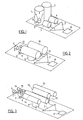
- FIG Fig. 2 Such an arrangement with a measuring cell 9 open on both sides, a reference cell 10 open on both sides, a measuring microphone 11 and a reference microphone 12 is shown in FIG Fig. 2 shown.
- this arrangement also has a second photocell 13, which is arranged in the region between the radiation source 5 and the measuring cell 1.
- the position of the second photocell 13 is selected so that in the presence of particles in the region between the radiation source 5 and measuring cell 1, a portion of the scattered light caused by these radiation of the radiation source 5 falls on the photocell 13.
- the second photocell 13 allows a distinction between aerosol and gas. If both the measuring cell 1 and the second photocell 13 a Signal, then an aerosol is present. If only the measuring cell 1 provides a signal, then either a gas or a very small and therefore non-scattering aerosol is present.
- the wavelength of the radiation source 5 is placed, for example, on the CO 2 line, then the measuring arrangement will be very sensitive on the one hand to measure the concentration of the combustion gas CO 2 and, on the other hand, the concentration of aerosol.
- the in the Fig. 1 and 2 illustrated measuring arrangement can be designed as a gas detector, as a smoke (aerosol) detector, as a combined gas and smoke detectors and they can be used in these various configurations as a fire alarm or as a fire hazard detector.
- a fire detector detects smoke and / or fumes, or in general, substances that characterize a fire.
- a fire hazard detector detects an already existing fire by detecting an aerosol or substances produced in a fire; on the other hand, it detects toxic substances arising in a fire, and it recognizes the danger of a possible fire or a possible explosion on the basis of the detection of the presence of combustible substances in the air.
- Substances which characterize a fire are in particular the following: CO 2 , CO, NO, NO 2 , SO 2 , NH 3 , HCl, HF, HCN, amines and amides, hydrocarbons, C, O and H containing compounds; Aerosols.
- Flammable substances are generally hydrocarbons, especially CH 4 , C 2 H 6 , C 3 H 8 , C 4 H 10 , C 2 H 2 , C 2 H 4 , and generally solvents, alcohols, ethers, ketones, aldehydes, amines and amides , in particular methanol, ethanol, n-propanol, diethyl ether, acetone.
- C, O and H containing compounds and carboxylic acids Other combustible substances which a fire hazard detector should detect are C, O and H containing compounds and carboxylic acids.
- Toxic substances are CO 2 , CO, NO, NO 2 , SO 2 , NH 3 , HCl, HF, HCN, H 2 S, nitriles, phosphoric acid esters, mercaptans, halogenated compounds.
- the resonance frequency can change accordingly.
- water vapor also influences the speed of sound and thus the resonance frequency.
- a temperature measurement can be used to calculate the approximate range of the resonant frequency and the additional possible expansion of the frequency range by varying the content of water vapor in the air and to temporally change the modulation frequency of the radiation source in this range (wobble).
- Another possibility of interference consists of frequencies in the room, which coincide with the resonant frequency. Such frequencies can cause both cells to vibrate but are not completely subtracted by the differential circuit to zero, because they impinge on the cells with a time shift due to the distance from the center of the measuring cell 1, 9 to the center of the reference cell 2, 10 and excite them to slightly phase-shifted oscillations. This phase shift can be minimized by the lowest possible resonant frequency, because then the disturbing sound frequencies have a large acoustic wavelength and the phase shift is small. Or you can measure the signal of the reference cell 2, 10 separately and increase the alarm threshold of the measuring arrangement when hitting a signal in the reference cell, which can indeed be generated only from the outside.
- the monitoring of the microphone sensitivity is recommended based on the zero point signals generated by the radiation source in the wall of the measuring cell 1, 9, which occur under all environmental conditions.
- the in the Fig. 1 and 2 shown arrangement for measuring / detecting smoke and a gas can be extended by an additional pair of cells for the measurement / detection of another gas.
- an additional measuring cell 14, an additional reference cell 15 and an additional radiation source 16 are provided, wherein, for example, the measuring cell 9 measures aerosol and a first gas and the measuring cell 14 measures a second gas.
- the two measuring cells 9 and 14 and correspondingly also the two reference cells 10 and 15 have different lengths and thus also different resonance frequencies and the two measuring cells are acted upon by the radiation sources 5 and 16 with radiation of different wavelengths.
- the two different resonance frequencies can be measured with only one measuring microphone 11.
- only a reference microphone 12 and only a single photocell 6 for monitoring the emission of the two radiation sources 5 and 16 is required.
- the measuring and reference cells may, for example, have the following dimensions: Measuring cell 9, reference cell 10: Length 2 cm each, resonant frequency 8.2 kHz each Measuring cell 14, reference cell 15: Length 2.2 cm each, resonant frequency 7.6 kHz each.
- the modulation frequency of the radiation source 5 is corresponding to 8.2 kHz and that of the radiation source 16 is 7.6 kHz. LEDs are used as radiation sources.
- Fig. 2 irradiate the measuring cell 9 of a cell pair with two radiation sources 5 and 16 at the same time and operate them with different frequencies.
- the radiation source 5 with the fundamental frequency and the radiation source 16 with the first overtone This requires compared to the arrangement of Fig. 3 only half the number of cells and microphones and saves costs accordingly.
- non-resonant, closed dual sensors are also known (see, for example, US Pat EP-A-0 855 592 ), which can also be designed so that with them the detection of aerosols and gases is possible.
- EP-A-0 855 592 can be seen, these optoacoustic dual sensors contain a measuring and a reference cell, which are completed by a membrane from the environment, and a radiation source. Gas can enter the cells through the membrane. It is a measurement and a reference microphone provided, wherein the reference microphone is shielded against opto-acoustic signals of the detected gas / aerosol. So that aerosol particles can penetrate into the cells, the pore size of the membranes is correspondingly increased.
- the membranes become acoustically soft for frequencies below 500 Hz, it is no longer possible to build up pressure in the cell and the sensitivity drops sharply.
- the membranes become acoustically hard again and the sensitivity no longer decreases.
- Eventual blockage of the membranes can be monitored by separately measuring the reference signal, which gives a basic level of noise, and tracks the sensitivity based on this baseline level. If you place the wavelength of the radiation source, for example, on the CO 2 line, then the measuring device is very sensitive measure the concentration of the combustion gas CO 2 . On the other hand, however, the concentration of aerosol is also measured very sensitively because cellulose and charred cellulose particles absorb intensively throughout the infrared. The volume per cell is about 2 times 2 times 2 cm 3 .
Landscapes
- Physics & Mathematics (AREA)
- Health & Medical Sciences (AREA)
- Life Sciences & Earth Sciences (AREA)
- Chemical & Material Sciences (AREA)
- Analytical Chemistry (AREA)
- Biochemistry (AREA)
- General Health & Medical Sciences (AREA)
- General Physics & Mathematics (AREA)
- Immunology (AREA)
- Pathology (AREA)
- Investigating Or Analysing Materials By Optical Means (AREA)
- Investigating Or Analyzing Materials By The Use Of Ultrasonic Waves (AREA)
- Investigating Or Analysing Biological Materials (AREA)
- Pens And Brushes (AREA)
- Golf Clubs (AREA)
- Confectionery (AREA)
Priority Applications (1)
| Application Number | Priority Date | Filing Date | Title |
|---|---|---|---|
| EP01969117A EP1325307B1 (de) | 2000-10-09 | 2001-10-01 | Optoakustische messanordnung und deren verwendung |
Applications Claiming Priority (6)
| Application Number | Priority Date | Filing Date | Title |
|---|---|---|---|
| EP00121937 | 2000-10-09 | ||
| EP00121937A EP1195597A1 (de) | 2000-10-09 | 2000-10-09 | Optoakustische Messanordnung und Verwendung der Messanordnung |
| CH8962001 | 2001-05-15 | ||
| CH8962001 | 2001-05-15 | ||
| EP01969117A EP1325307B1 (de) | 2000-10-09 | 2001-10-01 | Optoakustische messanordnung und deren verwendung |
| PCT/CH2001/000588 WO2002031475A1 (de) | 2000-10-09 | 2001-10-01 | Optoakustische messanordnung und deren verwendung |
Publications (2)
| Publication Number | Publication Date |
|---|---|
| EP1325307A1 EP1325307A1 (de) | 2003-07-09 |
| EP1325307B1 true EP1325307B1 (de) | 2009-03-04 |
Family
ID=25738771
Family Applications (1)
| Application Number | Title | Priority Date | Filing Date |
|---|---|---|---|
| EP01969117A Expired - Lifetime EP1325307B1 (de) | 2000-10-09 | 2001-10-01 | Optoakustische messanordnung und deren verwendung |
Country Status (12)
| Country | Link |
|---|---|
| US (1) | US7091869B2 (cs) |
| EP (1) | EP1325307B1 (cs) |
| KR (1) | KR100809130B1 (cs) |
| CN (1) | CN1250959C (cs) |
| AT (1) | ATE424554T1 (cs) |
| AU (1) | AU772018B2 (cs) |
| CZ (1) | CZ20021963A3 (cs) |
| DE (1) | DE50114746D1 (cs) |
| HU (1) | HUP0204193A2 (cs) |
| NO (1) | NO20022674L (cs) |
| PL (1) | PL354646A1 (cs) |
| WO (1) | WO2002031475A1 (cs) |
Families Citing this family (27)
| Publication number | Priority date | Publication date | Assignee | Title |
|---|---|---|---|---|
| CA2461328A1 (en) * | 2004-03-24 | 2005-09-24 | Robert Anthony Crane | A multiplexed type of spectrophone |
| US7797983B2 (en) * | 2004-03-29 | 2010-09-21 | Gasera Ltd. | Method and system for detecting one or more gases or gas mixtures and/or for measuring the concentration of one or more gases or gas mixtures |
| EP1715324A1 (de) * | 2005-04-18 | 2006-10-25 | Siemens Schweiz AG | Optoakustische Messanordnung für den Nachweis von Gasen und/oder Aerosolen |
| CN101163956B (zh) * | 2005-04-26 | 2011-02-02 | 皇家飞利浦电子股份有限公司 | 用于含氮气体化合物检测的低成本设备 |
| US7213444B2 (en) * | 2005-05-16 | 2007-05-08 | Carthago International Solutions, Inc. | Optoacoustic gas sensor |
| DE102005030151B3 (de) * | 2005-06-28 | 2006-11-02 | Fraunhofer-Gesellschaft zur Förderung der angewandten Forschung e.V. | Photoakustischer Freifelddetektor |
| KR100788795B1 (ko) * | 2006-08-29 | 2007-12-27 | 김성호 | 광 음향 검출기를 이용한 이산화탄소 농도 측정장치 |
| JP2010502943A (ja) * | 2006-08-31 | 2010-01-28 | コーニンクレッカ フィリップス エレクトロニクス エヌ ヴィ | 可変光強度変調器をもつ光空洞により増強された光音響式微量気体検出器 |
| US7886576B2 (en) * | 2006-11-06 | 2011-02-15 | Mine Safety Appliances Company | Photoacoustic gas sensor |
| US7782462B2 (en) | 2006-11-27 | 2010-08-24 | Applied Nanotech Holdings, Inc. | Sono-photonic gas sensor |
| DE102007026073B4 (de) * | 2007-05-25 | 2009-10-01 | Fraunhofer-Gesellschaft zur Förderung der angewandten Forschung e.V. | Vorrichtung und Verfahren zur Bestimmung der Permeationsrate mindestens eines Permeaten, durch ein eine Diffusionssperre bildendes Element |
| US7493816B1 (en) | 2007-09-28 | 2009-02-24 | Honeywell International Inc. | Smoke detectors |
| US8695402B2 (en) * | 2010-06-03 | 2014-04-15 | Honeywell International Inc. | Integrated IR source and acoustic detector for photoacoustic gas sensor |
| US8746038B2 (en) * | 2011-04-01 | 2014-06-10 | Honeywell International Inc. | Photoacoustic detector with acoustic and vibration noise compensation |
| US8945936B2 (en) | 2011-04-06 | 2015-02-03 | Fresenius Medical Care Holdings, Inc. | Measuring chemical properties of a sample fluid in dialysis systems |
| US8701465B2 (en) * | 2011-04-28 | 2014-04-22 | Honeywell International Inc. | Photoacoustic sensor diffusion membrane attachment structure |
| US9086364B2 (en) * | 2011-04-28 | 2015-07-21 | Honeywell International Inc. | Photoacoustic sensor with baseline and span correction |
| EP2604998A1 (de) * | 2011-12-12 | 2013-06-19 | ABB Research Ltd. | Vorrichtung zur Gasanalyse |
| US8848191B2 (en) | 2012-03-14 | 2014-09-30 | Honeywell International Inc. | Photoacoustic sensor with mirror |
| EP2634756A3 (de) * | 2013-06-10 | 2013-12-04 | Siemens Aktiengesellschaft | Tabakrauchmelder |
| FR3042866A1 (fr) * | 2015-10-21 | 2017-04-28 | Aerovia | Dispositif de detection de gaz a tres forte sensibilite base sur un resonateur de helmholtz |
| US11143626B2 (en) * | 2019-01-11 | 2021-10-12 | Infineon Technologies Ag | Photo-acoustic gas sensor with optimal reference path length |
| EP3550286B1 (en) * | 2019-04-17 | 2021-01-27 | Sensirion AG | Photoacoustic gas sensor device |
| CN110879203B (zh) * | 2019-12-09 | 2021-07-06 | 大连理工大学 | 一种高浓度甲烷背景中的微量乙烯气体测量系统及方法 |
| CN113516824B (zh) * | 2021-04-14 | 2023-05-12 | 汉威科技集团股份有限公司 | 一种复合型火灾探测器及其探测方法 |
| CN114739913B (zh) * | 2022-03-29 | 2022-10-28 | 安徽理工大学 | 一种基于双光声光谱的矿井粉尘实时检测系统及检测方法 |
| US11662301B1 (en) | 2022-03-29 | 2023-05-30 | Anhui University of Science and Technology | Mine dust real-time detection system based on double-photo acoustic spectrometry and detection method |
Family Cites Families (14)
| Publication number | Priority date | Publication date | Assignee | Title |
|---|---|---|---|---|
| FR1552069A (cs) | 1967-11-07 | 1969-01-03 | ||
| US4058725A (en) * | 1975-04-04 | 1977-11-15 | Aine Harry E | Infrared absorption spectrometer employing a dual optoacoustic detector |
| JPS595939A (ja) * | 1982-07-03 | 1984-01-12 | Horiba Ltd | パ−テイキユレ−ト連続測定装置 |
| US4688942A (en) * | 1982-11-26 | 1987-08-25 | The United State Of America As Represented By The Secretary Of The Navy | Radial and azmuthal non-resonant open-tubular optoacoustic cell |
| JPS59145957A (ja) * | 1983-01-08 | 1984-08-21 | Horiba Ltd | 光音響型濃度測定装置 |
| US4740086A (en) * | 1984-02-07 | 1988-04-26 | Oskar Oehler | Apparatus for the photoacoustic detection of gases |
| DK160590C (da) * | 1988-09-12 | 1991-09-16 | Fls Airloq As | Fremgangsmaade til detektering af en gasart ved hjaelp af fotoakustisk spektroskopi |
| DE4132110A1 (de) | 1991-09-26 | 1993-04-01 | Siemens Ag | Kraftsensor |
| US5331845A (en) * | 1993-01-19 | 1994-07-26 | Orbishpere Laboratories Neuchatel Sa | Probe and method for detecting alcohol |
| DE19637614A1 (de) | 1996-09-16 | 1997-11-13 | Bosch Gmbh Robert | Kraftsensor |
| DE19653427A1 (de) | 1996-12-20 | 1998-07-02 | Siemens Ag | Kraftsensor |
| US5933245A (en) * | 1996-12-31 | 1999-08-03 | Honeywell Inc. | Photoacoustic device and process for multi-gas sensing |
| EP0855592B1 (de) * | 1997-01-25 | 2006-07-12 | Siemens Schweiz AG | Optoakustischer Gassensor |
| DE19826629A1 (de) | 1998-06-17 | 1999-12-23 | Hbm Mes Und Systemtechnik Gmbh | Kraftmeßvorrichtung |
-
2001
- 2001-10-01 WO PCT/CH2001/000588 patent/WO2002031475A1/de not_active Ceased
- 2001-10-01 HU HU0204193A patent/HUP0204193A2/hu unknown
- 2001-10-01 US US10/148,949 patent/US7091869B2/en not_active Expired - Fee Related
- 2001-10-01 DE DE50114746T patent/DE50114746D1/de not_active Expired - Lifetime
- 2001-10-01 KR KR1020027007372A patent/KR100809130B1/ko not_active Expired - Fee Related
- 2001-10-01 AT AT01969117T patent/ATE424554T1/de not_active IP Right Cessation
- 2001-10-01 CN CNB018030793A patent/CN1250959C/zh not_active Expired - Fee Related
- 2001-10-01 EP EP01969117A patent/EP1325307B1/de not_active Expired - Lifetime
- 2001-10-01 PL PL01354646A patent/PL354646A1/xx not_active IP Right Cessation
- 2001-10-01 AU AU89464/01A patent/AU772018B2/en not_active Ceased
- 2001-10-01 CZ CZ20021963A patent/CZ20021963A3/cs unknown
-
2002
- 2002-06-06 NO NO20022674A patent/NO20022674L/no not_active Application Discontinuation
Also Published As
| Publication number | Publication date |
|---|---|
| HUP0204193A2 (en) | 2003-03-28 |
| NO20022674L (no) | 2002-07-24 |
| AU772018B2 (en) | 2004-04-08 |
| NO20022674D0 (no) | 2002-06-06 |
| US7091869B2 (en) | 2006-08-15 |
| EP1325307A1 (de) | 2003-07-09 |
| DE50114746D1 (de) | 2009-04-16 |
| PL354646A1 (en) | 2004-02-09 |
| CN1392952A (zh) | 2003-01-22 |
| WO2002031475A1 (de) | 2002-04-18 |
| CZ20021963A3 (cs) | 2002-11-13 |
| KR100809130B1 (ko) | 2008-02-29 |
| ATE424554T1 (de) | 2009-03-15 |
| US20030112019A1 (en) | 2003-06-19 |
| AU8946401A (en) | 2002-04-22 |
| CN1250959C (zh) | 2006-04-12 |
| KR20020071885A (ko) | 2002-09-13 |
Similar Documents
| Publication | Publication Date | Title |
|---|---|---|
| EP1325307B1 (de) | Optoakustische messanordnung und deren verwendung | |
| EP0855592B1 (de) | Optoakustischer Gassensor | |
| DE69111544T2 (de) | Sonde für die photoakustische Analyse. | |
| DE69114096T2 (de) | Photoakustische Zelle und photoakustische Messeinrichtung. | |
| DE102007014517B3 (de) | Zylindrischer photoakustischer Multipass-Detektor mit Anregung der zweiten azimutalen Resonanz | |
| DE102005030151B3 (de) | Photoakustischer Freifelddetektor | |
| DE4446723C2 (de) | Vorrichtung und Verfahren zur Messung der Konzentration eines Gases | |
| DE10051691A1 (de) | Gasdetektor mit geschlossener Zelle | |
| EP2132551B1 (de) | Photoakustischer detektor mit zwei strahlengängen für das anregungslicht | |
| DE3707622A1 (de) | Verfahren und vorrichtung zum messen geringer gaskonzentrationen | |
| EP1195597A1 (de) | Optoakustische Messanordnung und Verwendung der Messanordnung | |
| DE102006023061B4 (de) | Gasdetektor mit akustischer Messzelle und selektiv adsorbierender Oberfläche | |
| EP4006506B1 (de) | Verfahren zum bestimmen einer eigenschaft eines probenfluids oder einer resonanzfrequenz einer resonatorzelle | |
| DE102005053121A1 (de) | Partikelsensor | |
| DE3508027A1 (de) | Verfahren und einrichtung zum ermitteln der konzentration oder der massenanteile bestimmter gase in gasmischungen | |
| EP2132552A1 (de) | Verfahren und vorrichtung zur messung des photoakustischen signals mit rechnergestützter auswertung | |
| WO2025003488A1 (de) | Sensor zum bestimmen der konzentration eines gases | |
| EP1715324A1 (de) | Optoakustische Messanordnung für den Nachweis von Gasen und/oder Aerosolen | |
| DE4034375A1 (de) | Gas-messeinrichtung | |
| EP1463929A1 (de) | Verfahren und anordnung zur fremdgaserkennung in optischen abbildungs- und/oder strahlführungssystemen | |
| DE102004053480B3 (de) | Verfahren zur Analyse und Konzentrationsmessung | |
| EP1367383B1 (de) | Optischer Gasmelder | |
| DE102007018846A1 (de) | Vorrichtung und Verfahren zur simultanen photoakustischen Absorptionsmessung von Gasen und Aerosolen bei mehreren Wellenlängen mit nur einer Laserlichtquelle | |
| DE102024001415A1 (de) | QEPAS Sensor zur Analyse von Feststoffen und Flüssigkeiten | |
| DE19540236A1 (de) | Sensor für elektromagnetische Strahlung |
Legal Events
| Date | Code | Title | Description |
|---|---|---|---|
| PUAI | Public reference made under article 153(3) epc to a published international application that has entered the european phase |
Free format text: ORIGINAL CODE: 0009012 |
|
| 17P | Request for examination filed |
Effective date: 20020918 |
|
| AK | Designated contracting states |
Designated state(s): AT BE CH CY DE DK ES FI FR GB GR IE IT LI LU MC NL PT SE TR |
|
| 17Q | First examination report despatched |
Effective date: 20070510 |
|
| R17C | First examination report despatched (corrected) |
Effective date: 20070829 |
|
| R17C | First examination report despatched (corrected) |
Effective date: 20070926 |
|
| RAP1 | Party data changed (applicant data changed or rights of an application transferred) |
Owner name: SIEMENS AKTIENGESELLSCHAFT |
|
| R17C | First examination report despatched (corrected) |
Effective date: 20080123 |
|
| GRAP | Despatch of communication of intention to grant a patent |
Free format text: ORIGINAL CODE: EPIDOSNIGR1 |
|
| GRAS | Grant fee paid |
Free format text: ORIGINAL CODE: EPIDOSNIGR3 |
|
| GRAA | (expected) grant |
Free format text: ORIGINAL CODE: 0009210 |
|
| AK | Designated contracting states |
Kind code of ref document: B1 Designated state(s): AT BE CH CY DE DK ES FI FR GB GR IE IT LI LU MC NL PT SE TR |
|
| REG | Reference to a national code |
Ref country code: GB Ref legal event code: FG4D Free format text: NOT ENGLISH |
|
| REG | Reference to a national code |
Ref country code: CH Ref legal event code: EP |
|
| REG | Reference to a national code |
Ref country code: IE Ref legal event code: FG4D Free format text: LANGUAGE OF EP DOCUMENT: GERMAN |
|
| REF | Corresponds to: |
Ref document number: 50114746 Country of ref document: DE Date of ref document: 20090416 Kind code of ref document: P |
|
| PG25 | Lapsed in a contracting state [announced via postgrant information from national office to epo] |
Ref country code: FI Free format text: LAPSE BECAUSE OF FAILURE TO SUBMIT A TRANSLATION OF THE DESCRIPTION OR TO PAY THE FEE WITHIN THE PRESCRIBED TIME-LIMIT Effective date: 20090304 Ref country code: NL Free format text: LAPSE BECAUSE OF FAILURE TO SUBMIT A TRANSLATION OF THE DESCRIPTION OR TO PAY THE FEE WITHIN THE PRESCRIBED TIME-LIMIT Effective date: 20090304 |
|
| NLV1 | Nl: lapsed or annulled due to failure to fulfill the requirements of art. 29p and 29m of the patents act | ||
| PG25 | Lapsed in a contracting state [announced via postgrant information from national office to epo] |
Ref country code: SE Free format text: LAPSE BECAUSE OF FAILURE TO SUBMIT A TRANSLATION OF THE DESCRIPTION OR TO PAY THE FEE WITHIN THE PRESCRIBED TIME-LIMIT Effective date: 20090604 |
|
| REG | Reference to a national code |
Ref country code: IE Ref legal event code: FD4D |
|
| PG25 | Lapsed in a contracting state [announced via postgrant information from national office to epo] |
Ref country code: ES Free format text: LAPSE BECAUSE OF FAILURE TO SUBMIT A TRANSLATION OF THE DESCRIPTION OR TO PAY THE FEE WITHIN THE PRESCRIBED TIME-LIMIT Effective date: 20090615 Ref country code: PT Free format text: LAPSE BECAUSE OF FAILURE TO SUBMIT A TRANSLATION OF THE DESCRIPTION OR TO PAY THE FEE WITHIN THE PRESCRIBED TIME-LIMIT Effective date: 20090819 Ref country code: IE Free format text: LAPSE BECAUSE OF FAILURE TO SUBMIT A TRANSLATION OF THE DESCRIPTION OR TO PAY THE FEE WITHIN THE PRESCRIBED TIME-LIMIT Effective date: 20090304 |
|
| PLBE | No opposition filed within time limit |
Free format text: ORIGINAL CODE: 0009261 |
|
| STAA | Information on the status of an ep patent application or granted ep patent |
Free format text: STATUS: NO OPPOSITION FILED WITHIN TIME LIMIT |
|
| PG25 | Lapsed in a contracting state [announced via postgrant information from national office to epo] |
Ref country code: DK Free format text: LAPSE BECAUSE OF FAILURE TO SUBMIT A TRANSLATION OF THE DESCRIPTION OR TO PAY THE FEE WITHIN THE PRESCRIBED TIME-LIMIT Effective date: 20090304 |
|
| 26N | No opposition filed |
Effective date: 20091207 |
|
| BERE | Be: lapsed |
Owner name: SIEMENS A.G. Effective date: 20091031 |
|
| PG25 | Lapsed in a contracting state [announced via postgrant information from national office to epo] |
Ref country code: MC Free format text: LAPSE BECAUSE OF NON-PAYMENT OF DUE FEES Effective date: 20091031 |
|
| REG | Reference to a national code |
Ref country code: CH Ref legal event code: PL |
|
| REG | Reference to a national code |
Ref country code: FR Ref legal event code: ST Effective date: 20100630 |
|
| PG25 | Lapsed in a contracting state [announced via postgrant information from national office to epo] |
Ref country code: FR Free format text: LAPSE BECAUSE OF NON-PAYMENT OF DUE FEES Effective date: 20091102 |
|
| PG25 | Lapsed in a contracting state [announced via postgrant information from national office to epo] |
Ref country code: LI Free format text: LAPSE BECAUSE OF NON-PAYMENT OF DUE FEES Effective date: 20091031 Ref country code: BE Free format text: LAPSE BECAUSE OF NON-PAYMENT OF DUE FEES Effective date: 20091031 Ref country code: CH Free format text: LAPSE BECAUSE OF NON-PAYMENT OF DUE FEES Effective date: 20091031 Ref country code: GR Free format text: LAPSE BECAUSE OF FAILURE TO SUBMIT A TRANSLATION OF THE DESCRIPTION OR TO PAY THE FEE WITHIN THE PRESCRIBED TIME-LIMIT Effective date: 20090605 |
|
| PG25 | Lapsed in a contracting state [announced via postgrant information from national office to epo] |
Ref country code: GB Free format text: LAPSE BECAUSE OF NON-PAYMENT OF DUE FEES Effective date: 20091001 |
|
| PG25 | Lapsed in a contracting state [announced via postgrant information from national office to epo] |
Ref country code: AT Free format text: LAPSE BECAUSE OF NON-PAYMENT OF DUE FEES Effective date: 20091001 |
|
| PG25 | Lapsed in a contracting state [announced via postgrant information from national office to epo] |
Ref country code: IT Free format text: LAPSE BECAUSE OF FAILURE TO SUBMIT A TRANSLATION OF THE DESCRIPTION OR TO PAY THE FEE WITHIN THE PRESCRIBED TIME-LIMIT Effective date: 20090304 |
|
| PG25 | Lapsed in a contracting state [announced via postgrant information from national office to epo] |
Ref country code: LU Free format text: LAPSE BECAUSE OF NON-PAYMENT OF DUE FEES Effective date: 20091001 |
|
| PG25 | Lapsed in a contracting state [announced via postgrant information from national office to epo] |
Ref country code: TR Free format text: LAPSE BECAUSE OF FAILURE TO SUBMIT A TRANSLATION OF THE DESCRIPTION OR TO PAY THE FEE WITHIN THE PRESCRIBED TIME-LIMIT Effective date: 20090304 |
|
| PG25 | Lapsed in a contracting state [announced via postgrant information from national office to epo] |
Ref country code: CY Free format text: LAPSE BECAUSE OF FAILURE TO SUBMIT A TRANSLATION OF THE DESCRIPTION OR TO PAY THE FEE WITHIN THE PRESCRIBED TIME-LIMIT Effective date: 20090304 |
|
| PGFP | Annual fee paid to national office [announced via postgrant information from national office to epo] |
Ref country code: DE Payment date: 20111219 Year of fee payment: 11 |
|
| PG25 | Lapsed in a contracting state [announced via postgrant information from national office to epo] |
Ref country code: DE Free format text: LAPSE BECAUSE OF NON-PAYMENT OF DUE FEES Effective date: 20130501 |
|
| REG | Reference to a national code |
Ref country code: DE Ref legal event code: R119 Ref document number: 50114746 Country of ref document: DE Effective date: 20130501 |