EP1325307B1 - Optoacoustic measuring arrangement and use thereof - Google Patents
Optoacoustic measuring arrangement and use thereof Download PDFInfo
- Publication number
- EP1325307B1 EP1325307B1 EP01969117A EP01969117A EP1325307B1 EP 1325307 B1 EP1325307 B1 EP 1325307B1 EP 01969117 A EP01969117 A EP 01969117A EP 01969117 A EP01969117 A EP 01969117A EP 1325307 B1 EP1325307 B1 EP 1325307B1
- Authority
- EP
- European Patent Office
- Prior art keywords
- measuring
- radiation
- cell
- measuring cell
- radiation source
- Prior art date
- Legal status (The legal status is an assumption and is not a legal conclusion. Google has not performed a legal analysis and makes no representation as to the accuracy of the status listed.)
- Expired - Lifetime
Links
Images
Classifications
-
- G—PHYSICS
- G01—MEASURING; TESTING
- G01N—INVESTIGATING OR ANALYSING MATERIALS BY DETERMINING THEIR CHEMICAL OR PHYSICAL PROPERTIES
- G01N21/00—Investigating or analysing materials by the use of optical means, i.e. using sub-millimetre waves, infrared, visible or ultraviolet light
- G01N21/17—Systems in which incident light is modified in accordance with the properties of the material investigated
- G01N21/1702—Systems in which incident light is modified in accordance with the properties of the material investigated with opto-acoustic detection, e.g. for gases or analysing solids
- G01N2021/1704—Systems in which incident light is modified in accordance with the properties of the material investigated with opto-acoustic detection, e.g. for gases or analysing solids in gases
Definitions
- the present invention relates to an opto-acoustic measuring arrangement for the detection of gases and / or aerosols, each having a measuring and reference cell and associated microphones, to which an evaluation is connected, in which a subtraction of the signals of the microphones takes place, and with a radiation source for the modulated loading of the measuring cell, the modulation frequency of the radiation source coinciding with the resonance frequency of the measuring cell.
- the US 4594004 describes an optoacoustic measuring device for continuously determining the concentration of particles contained in a gas, which has two measuring cells, which are irradiated in parallel to each other by the light of a laser.
- the first measuring cell is fed gas without particles.
- In the optical path in front of each of the two measuring cells is a chopper.
- the first chopper is operated at a chopper frequency which corresponds to the resonant frequency of the first measuring cell, while the chopper frequency of the second chopper corresponds to the resonant frequency of the second measuring cell.
- a measuring device can be z. B. the proportion of particles in exhaust gases, z. B. of vehicles, certain.
- the EP 0855592 describes a gas sensor.
- the gas sensor consists of a sensor body which has a light source, a measuring cell with a gas-permeable membrane and a measuring microphone and an optical measuring filter arranged between the light source and the measuring cell.
- the sensor body contains a separate from the measuring cell reference cell with a reference microphone, which is shielded against opto-acoustic signals of the gas to be measured.
- the measurement signal indicating the concentration of the gas to be detected is obtained by subtracting the signals of the two microphones.
- the irradiation of a gas to be detected by modulated light causes an acoustic pressure wave whose magnitude is directly related to the concentration of the relevant gas.
- the acoustic pressure wave arises because the gas absorbs the light radiation and thereby heats up. This results in a thermal expansion and, according to the modulation of the light radiation, a periodic pressure fluctuation.
- the two cells are usually referred to as measuring and reference cell, and the measuring arrangement is designed so that either the cells separated from each other and the radiation intersperses both cells ( CF Dewey, Jr.: Opto-acoustic Spectroscopy and Detection, [YH Pao, ed.], Academic Press, New York, 1977, 47-77 ) or the cells are interconnected and the radiation only passes through the measuring cell ( G. Busse and D. Herboeck: Differential Helmholtz resonator as an opto-acoustic detector, Applied Optics, Vol. 23, 3959 ).
- the detection of aerosols is similar, and they also absorb the modulated radiation, producing modulated heat and modulated pressure.
- Optoacoustic sensors for the measurement of aerosols described so far are mostly mono sensors with only one measuring cell. If sensors with two cells, so-called dual sensors with a measuring and a reference cell are proposed for the aerosol measurement, then these are constructed so that the reference cell is shielded against aerosol. The latter is achieved by filtering the air before it enters the reference cell.
- the detection sensitivity of optoacoustic sensors for gases or aerosols is in the range of those of optical smoke detectors. Because the optoacoustic Signals are generated by absorption and not by scattering, could be detected with the optoacoustic principle both large and very small aerosols to below the ⁇ -range and bright and dark smokes could be measured about equally well. Nevertheless, so far, the optoacoustic principle for smoke detection is not used, which is mainly due to the additional effort required for the air filtering and the correction of the signal size.
- the invention will now be an opto-acoustic measuring arrangement of the type mentioned above, the cost of which are competitive with those of a scattered light detector.
- measuring cell and the reference cell are open at least on one side with respect to the gas and / or aerosol to be detected.
- the sensor signal is normally zero, and only in the presence of aerosol or a combustible gas which absorbs the radiation emitted by the radiation source, a signal is generated in the measuring cell, which requires only a relatively simple electronics for its processing.
- the wavelength of the radiation emitted by the radiation source is selected such that it is absorbed by a gas to be detected.
- a first photocell for monitoring the intensity of the radiation emitted by the radiation source is arranged in the region of the radiation source.
- a second photocell is arranged, which is acted upon in the presence of an aerosol caused by this scattered radiation of the radiation source.
- a first preferred embodiment of the measuring arrangement according to the invention is characterized in that the evaluation electronics include a differential amplifier and a phase-sensitive rectifier.
- a measuring arrangement formed in this way can detect both an aerosol, ie smoke, as well as a gas and is therefore ideally suited for use as a so-called two-criteria detector for smoke and gas.
- an aerosol ie smoke
- a gas ie smoke
- two-criteria detector for smoke and gas.
- it behaves so that a certain aerosol absorbs in a certain wavelength range, the type of aerosol depends on the fire.
- the smoke of a fire almost always contains mixtures of organic substances, such as wood, which in the entire infrared range Strong and in the visible light still absorb enough, the choice of wavelength for optimal aerosol detection is not critical.
- the second photocell is not required, because in that case a wavelength can be selected at which no combustible gases absorb.
- the lateral photocell is in any case required if a gas is to be detected whose absorption range is that of aerosol.
- a second preferred embodiment of the measuring arrangement according to the invention is characterized in that the measuring cell is irradiated with two radiation sources which are operated at different frequencies. This arrangement is suitable for the detection of smoke and two gases.
- a further preferred embodiment of the measuring arrangement according to the invention is characterized in that two pairs of measurement and reference cells open on both sides are provided, each having different length and thus different resonance frequencies, each associated with each reference and each pair of measuring cells, and each measuring cell is acted upon by a radiation source.
- the measuring arrangement with the two pairs of measuring and reference cells is suitable for detecting smoke and two gases.
- the detection range of the measuring arrangement can be extended to a third gas.
- the invention further relates to a use of said measuring arrangement as a smoke detector.
- This use is characterized in that the measuring arrangement comprises a measuring cell, which is acted upon by a radiation of a wavelength at which the aerosol to be detected is absorbed and thereby an opto-acoustic effect is generated.
- the invention further relates to a use of said measuring arrangement as a fire hazard detector.
- This use is characterized in that the measuring arrangement has a measuring cell, which is acted upon by a radiation of a wavelength at which absorbs a combustible or explosive substance to be detected and thereby an optoacoustic effect is generated.
- the invention further relates to a use of said measuring arrangement as a combined smoke and gas detector.
- This use is characterized in that the measuring arrangement has a measuring cell, which is acted upon by radiation of a wavelength at which a combustible or explosive substance to be detected absorbs and thereby an optoacoustic effect is generated, and in that way a photocell is arranged next to the measuring cell is that it is acted upon by radiation caused by an aerosol scattered light of the radiation.
- the invention further relates to a use of said measuring arrangement as a combined fire and fire hazard.
- This use is characterized in that the measuring arrangement comprises two measuring cells, one of which is exposed to radiation of a wavelength at which the aerosol to be detected and / or a combustion gas absorbs, and the other of which is exposed to radiation of a wavelength at which one absorbed flammable or explosive substance and thereby an optoacoustic effect is generated.
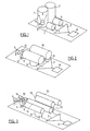
- a radiation source 5 for example an LED, is provided, which acts on the interior of the measuring cell 1 with radiation of a specific wavelength.
- a first photocell 6 is arranged for monitoring the intensity of the radiation emitted by the radiation source 5.
- the outputs of the two microphones 3 and 4 are led to a differential amplifier 7, in which the microphone signals are subtracted from each other.
- the output signal of the differential amplifier 7 is fed to a phase-sensitive rectifier (lock-in) 8.
- the radiation source 5 radiates modulated into the measuring cell 1, wherein the modulation frequency of the radiation source 5 coincides with the resonance frequency of the measuring cell. If the measuring cell 1 contains an aerosol, then this absorbs the modulated radiation, whereby modulated heat is generated. The modulated heat generates modulated pressure and thereby sound at the frequency of the resonance frequency of the measuring cell 1, whereby the air column is excited to vibrate in the measuring cell. The same applies in the presence of a gas in the measuring cell 1.
- the microphone 3, which is located at the location of a pressure belly of the standing wave, measures the vibrations ( sound) in the tube. As soon as the microphone 3 measures a tone which coincides with the resonance frequency of the measuring cell 1, an aerosol and / or a gas is located in the measuring cell 1.
- the illustrated measuring arrangement responds equally well to dark and light aerosols: dark aerosols give a large signal because even at the first impact of the radiation of the radiation source 5 on a particle much radiation power is absorbed. And bright aerosols also give a big signal, because the radiation is reflected several times on the bright particles and in sum is also strongly absorbed.
- the optoacoustic sensor responds to large aerosols as well as to very small ones below the ⁇ range, since the optoacoustic signals are generated by absorption rather than scattering.
- the microphone 3 measures not only the resonant vibrations in the measuring cell 1, but also all the noise in the room, which can lead to disturbances. These disturbances are eliminated by the reference cell 2 and the microphone 4. Since the reference cell 2 is not exposed to the radiation of a radiation source, the microphone 4 can not measure any vibrations caused by a radiation source, but measures only the sounds of the room. The signals of the reference microphone 4 are subtracted in the differential amplifier 8 from the signals of the measuring microphone 3, whereby the sounds of the room are eliminated. Also eliminated are vibrations that act equally on both microphones.
- the two cells, measuring cell and reference cell can also be open on both sides.
- FIG Fig. 2 Such an arrangement with a measuring cell 9 open on both sides, a reference cell 10 open on both sides, a measuring microphone 11 and a reference microphone 12 is shown in FIG Fig. 2 shown.
- this arrangement also has a second photocell 13, which is arranged in the region between the radiation source 5 and the measuring cell 1.
- the position of the second photocell 13 is selected so that in the presence of particles in the region between the radiation source 5 and measuring cell 1, a portion of the scattered light caused by these radiation of the radiation source 5 falls on the photocell 13.
- the second photocell 13 allows a distinction between aerosol and gas. If both the measuring cell 1 and the second photocell 13 a Signal, then an aerosol is present. If only the measuring cell 1 provides a signal, then either a gas or a very small and therefore non-scattering aerosol is present.
- the wavelength of the radiation source 5 is placed, for example, on the CO 2 line, then the measuring arrangement will be very sensitive on the one hand to measure the concentration of the combustion gas CO 2 and, on the other hand, the concentration of aerosol.
- the in the Fig. 1 and 2 illustrated measuring arrangement can be designed as a gas detector, as a smoke (aerosol) detector, as a combined gas and smoke detectors and they can be used in these various configurations as a fire alarm or as a fire hazard detector.
- a fire detector detects smoke and / or fumes, or in general, substances that characterize a fire.
- a fire hazard detector detects an already existing fire by detecting an aerosol or substances produced in a fire; on the other hand, it detects toxic substances arising in a fire, and it recognizes the danger of a possible fire or a possible explosion on the basis of the detection of the presence of combustible substances in the air.
- Substances which characterize a fire are in particular the following: CO 2 , CO, NO, NO 2 , SO 2 , NH 3 , HCl, HF, HCN, amines and amides, hydrocarbons, C, O and H containing compounds; Aerosols.
- Flammable substances are generally hydrocarbons, especially CH 4 , C 2 H 6 , C 3 H 8 , C 4 H 10 , C 2 H 2 , C 2 H 4 , and generally solvents, alcohols, ethers, ketones, aldehydes, amines and amides , in particular methanol, ethanol, n-propanol, diethyl ether, acetone.
- C, O and H containing compounds and carboxylic acids Other combustible substances which a fire hazard detector should detect are C, O and H containing compounds and carboxylic acids.
- Toxic substances are CO 2 , CO, NO, NO 2 , SO 2 , NH 3 , HCl, HF, HCN, H 2 S, nitriles, phosphoric acid esters, mercaptans, halogenated compounds.
- the resonance frequency can change accordingly.
- water vapor also influences the speed of sound and thus the resonance frequency.
- a temperature measurement can be used to calculate the approximate range of the resonant frequency and the additional possible expansion of the frequency range by varying the content of water vapor in the air and to temporally change the modulation frequency of the radiation source in this range (wobble).
- Another possibility of interference consists of frequencies in the room, which coincide with the resonant frequency. Such frequencies can cause both cells to vibrate but are not completely subtracted by the differential circuit to zero, because they impinge on the cells with a time shift due to the distance from the center of the measuring cell 1, 9 to the center of the reference cell 2, 10 and excite them to slightly phase-shifted oscillations. This phase shift can be minimized by the lowest possible resonant frequency, because then the disturbing sound frequencies have a large acoustic wavelength and the phase shift is small. Or you can measure the signal of the reference cell 2, 10 separately and increase the alarm threshold of the measuring arrangement when hitting a signal in the reference cell, which can indeed be generated only from the outside.
- the monitoring of the microphone sensitivity is recommended based on the zero point signals generated by the radiation source in the wall of the measuring cell 1, 9, which occur under all environmental conditions.
- the in the Fig. 1 and 2 shown arrangement for measuring / detecting smoke and a gas can be extended by an additional pair of cells for the measurement / detection of another gas.
- an additional measuring cell 14, an additional reference cell 15 and an additional radiation source 16 are provided, wherein, for example, the measuring cell 9 measures aerosol and a first gas and the measuring cell 14 measures a second gas.
- the two measuring cells 9 and 14 and correspondingly also the two reference cells 10 and 15 have different lengths and thus also different resonance frequencies and the two measuring cells are acted upon by the radiation sources 5 and 16 with radiation of different wavelengths.
- the two different resonance frequencies can be measured with only one measuring microphone 11.
- only a reference microphone 12 and only a single photocell 6 for monitoring the emission of the two radiation sources 5 and 16 is required.
- the measuring and reference cells may, for example, have the following dimensions: Measuring cell 9, reference cell 10: Length 2 cm each, resonant frequency 8.2 kHz each Measuring cell 14, reference cell 15: Length 2.2 cm each, resonant frequency 7.6 kHz each.
- the modulation frequency of the radiation source 5 is corresponding to 8.2 kHz and that of the radiation source 16 is 7.6 kHz. LEDs are used as radiation sources.
- Fig. 2 irradiate the measuring cell 9 of a cell pair with two radiation sources 5 and 16 at the same time and operate them with different frequencies.
- the radiation source 5 with the fundamental frequency and the radiation source 16 with the first overtone This requires compared to the arrangement of Fig. 3 only half the number of cells and microphones and saves costs accordingly.
- non-resonant, closed dual sensors are also known (see, for example, US Pat EP-A-0 855 592 ), which can also be designed so that with them the detection of aerosols and gases is possible.
- EP-A-0 855 592 can be seen, these optoacoustic dual sensors contain a measuring and a reference cell, which are completed by a membrane from the environment, and a radiation source. Gas can enter the cells through the membrane. It is a measurement and a reference microphone provided, wherein the reference microphone is shielded against opto-acoustic signals of the detected gas / aerosol. So that aerosol particles can penetrate into the cells, the pore size of the membranes is correspondingly increased.
- the membranes become acoustically soft for frequencies below 500 Hz, it is no longer possible to build up pressure in the cell and the sensitivity drops sharply.
- the membranes become acoustically hard again and the sensitivity no longer decreases.
- Eventual blockage of the membranes can be monitored by separately measuring the reference signal, which gives a basic level of noise, and tracks the sensitivity based on this baseline level. If you place the wavelength of the radiation source, for example, on the CO 2 line, then the measuring device is very sensitive measure the concentration of the combustion gas CO 2 . On the other hand, however, the concentration of aerosol is also measured very sensitively because cellulose and charred cellulose particles absorb intensively throughout the infrared. The volume per cell is about 2 times 2 times 2 cm 3 .
Abstract
Description
Die vorliegende Erfindung betrifft eine optoakustische Messanordnung für den Nachweis von Gasen und/oder Aerosolen, mit je einer Mess- und Referenzzelle und diesen zugeordneten Mikrofonen, an welche eine Auswerteelektronik angeschlossen ist, in welcher eine Subtraktion der Signale der Mikrofone erfolgt, und mit einer Strahlungsquelle zur modulierten Beaufschlagung der Messzelle, wobei die Modulationsfrequenz der Strahlungsquelle mit der Resonanzfrequenz der Messzelle übereinstimmt.The present invention relates to an opto-acoustic measuring arrangement for the detection of gases and / or aerosols, each having a measuring and reference cell and associated microphones, to which an evaluation is connected, in which a subtraction of the signals of the microphones takes place, and with a radiation source for the modulated loading of the measuring cell, the modulation frequency of the radiation source coinciding with the resonance frequency of the measuring cell.
Die
Die
Beim optoakustischen oder fotoakustischen Effekt wird durch die Bestrahlung eines zu detektierenden Gases durch moduliertes Licht eine akustische Druckwelle verursacht, deren Grösse in direktem Verhältnis zur Konzentration des betreffenden Gases steht. Die akustische Druckwelle entsteht deswegen, weil das Gas die Lichtstrahlung absorbiert und sich dadurch erwärmt. Daraus resultiert eine thermische Ausdehnung und, entsprechend der Modulation der Lichtstrahlung, eine periodische Druckschwankung. Die beiden Zellen werden in der Regel als Mess- und Referenzzelle bezeichnet, und die Messanordnung ist so ausgebildet, dass entweder die Zellen voneinander getrennt sind und die Strahlung beide Zellen durchsetzt (
Beim Nachweis von Aerosolen verhält es sich ähnlich, auch diese absorbieren die modulierte Strahlung, wodurch modulierte Wärme und von dieser modulierter Druck erzeugt wird. Bisher beschriebene optoakustische Sensoren für die Messung von Aerosolen sind meistens Monosensoren mit nur einer Messzelle. Wenn für die Aerosolmessung Sensoren mit zwei Zellen, sogenannte Dualsensoren mit einer Mess- und einer Referenzzelle vorgeschlagen werden, dann sind diese so aufgebaut, dass die Referenzzelle gegen Aerosol abgeschirmt ist. Letzteres wird dadurch erreicht, dass die Luft gefiltert wird, bevor sie in die Referenzzelle gelangt. Ausserdem wird auf die starke Temperaturabhängigkeit der Resonanzfrequenz hingewiesen, welche eine Korrektur der Signalgrösse erfordert.The detection of aerosols is similar, and they also absorb the modulated radiation, producing modulated heat and modulated pressure. Optoacoustic sensors for the measurement of aerosols described so far are mostly mono sensors with only one measuring cell. If sensors with two cells, so-called dual sensors with a measuring and a reference cell are proposed for the aerosol measurement, then these are constructed so that the reference cell is shielded against aerosol. The latter is achieved by filtering the air before it enters the reference cell. In addition, attention is drawn to the strong temperature dependence of the resonance frequency, which requires a correction of the signal magnitude.
Bei Anwendung des Dual-Prinzips liegt die Nachweisempfindlichkeit optoakustischer Sensoren für Gase oder Aerosole im Bereich derjenigen von optischen Rauchmeldern. Da die optoakustischen Signale durch Absorption und nicht durch Streuung erzeugt werden, könnten mit dem optoakustischen Prinzip sowohl grosse und auch kleinste Aerosole bis unterhalb des µ-Bereichs detektiert und helle und dunkle Raucharten könnten etwa gleich gut gemessen werden. Trotzdem wird bisher das optoakustische Prinzip zur Rauchdetektion nicht verwendet, was hauptsächlich durch den für die Luftfilterung und die Korrektur der Signalgrösse erforderlichen zusätzlichen Aufwand bedingt ist.When using the dual principle, the detection sensitivity of optoacoustic sensors for gases or aerosols is in the range of those of optical smoke detectors. Because the optoacoustic Signals are generated by absorption and not by scattering, could be detected with the optoacoustic principle both large and very small aerosols to below the μ-range and bright and dark smokes could be measured about equally well. Nevertheless, so far, the optoacoustic principle for smoke detection is not used, which is mainly due to the additional effort required for the air filtering and the correction of the signal size.
Durch die Erfindung soll nun eine optoakustische Messanordnung der eingangs genannten Art angegeben werden, deren Kosten mit denjenigen eines Streulichtmelders konkurrenzfähig sind.The invention will now be an opto-acoustic measuring arrangement of the type mentioned above, the cost of which are competitive with those of a scattered light detector.
Diese Aufgabe wird erfindungsgemäss dadurch gelöst, dass die Mess- und die Referenzzelle gegenüber dem nachzuweisenden Gas und/oder Aerosol mindestens einseitig offen sind.This object is achieved according to the invention in that the measuring cell and the reference cell are open at least on one side with respect to the gas and / or aerosol to be detected.
Da bei der erfindungsgemässen optoakustischen Messanordnung beide Zellen gegenüber dem nachzuweisenden Gas und/oder Aerosol offen sind, ist eine Filterung des zu untersuchenden Gases/Aerosols nicht erforderlich. Das Sensorsignal ist im Normalfall gleich Null, und erst bei Anwesenheit von Aerosol oder eines brennbaren Gases, welches die von der Strahlungsquelle ausgesandte Strahlung absorbiert, wird in der Messzelle ein Signal erzeugt, welches zu seiner verarbeitung nur eine relativ einfache Elektronik benötigt. Die Wellenlänge der von der Strahlungsquelle ausgesandten Strahlung ist so gewählt, dass sie von einem nachzuweisenden Gas absorbiert wird. Vorzugsweise ist im Bereich der Strahlungsquelle eine erste Fotozelle zur Überwachung der Intensität der von der Strahlungsquelle ausgesandten Strahlung angeordnet. Neben der Messzelle ist eine zweite Fotozelle angeordnet, welche bei Vorhandensein eines Aerosols von der durch dieses verursachten Streustrahlung der Strahlungsquelle beaufschlagt ist.Since both cells are open to the gas and / or aerosol to be detected in the optoacoustic measuring arrangement according to the invention, it is not necessary to filter the gas / aerosol to be investigated. The sensor signal is normally zero, and only in the presence of aerosol or a combustible gas which absorbs the radiation emitted by the radiation source, a signal is generated in the measuring cell, which requires only a relatively simple electronics for its processing. The wavelength of the radiation emitted by the radiation source is selected such that it is absorbed by a gas to be detected. Preferably, a first photocell for monitoring the intensity of the radiation emitted by the radiation source is arranged in the region of the radiation source. In addition to the measuring cell, a second photocell is arranged, which is acted upon in the presence of an aerosol caused by this scattered radiation of the radiation source.
Eine erste bevorzugte Ausführungsform der erfindungsgemässen Messanordnung ist dadurch gekennzeichnet, dass die Auswerteelektronik einen Differenzverstärker und einen phasenempfindlichen Gleichrichter enthält.A first preferred embodiment of the measuring arrangement according to the invention is characterized in that the evaluation electronics include a differential amplifier and a phase-sensitive rectifier.
Eine auf diese Weise ausgebildete Messanordnung kann also sowohl ein Aerosol, also Rauch, als auch ein Gas nachweisen und ist damit hervorragend für die Verwendung als sogenannter Zweikriterienmelder für Rauch und Gas geeignet. Es verhält sich in der Praxis so, dass ein bestimmtes Aerosol in einem bestimmten Wellenlängenbereich absorbiert, wobei die Art des Aerosols vom Brandgut abhängt. Da aber der Rauch eines Feuers praktisch immer auch Mischungen von organischen Substanzen, wie beispielsweise Holz, enthält, welche im gesamten Infrarotbereich stark und im Bereich des sichtbaren Lichts immer noch ausreichend absorbieren, ist die Wahl der Wellenlänge für einen optimalen Aerosolnachweis nicht kritisch.Thus, a measuring arrangement formed in this way can detect both an aerosol, ie smoke, as well as a gas and is therefore ideally suited for use as a so-called two-criteria detector for smoke and gas. In practice, it behaves so that a certain aerosol absorbs in a certain wavelength range, the type of aerosol depends on the fire. However, since the smoke of a fire almost always contains mixtures of organic substances, such as wood, which in the entire infrared range Strong and in the visible light still absorb enough, the choice of wavelength for optimal aerosol detection is not critical.
Wenn nur Rauch nachgewiesen werden soll, ist die zweiteFotozelle nicht erforderlich, weil in diesem Fall eine Wellenlänge gewählt werden kann, bei der keine brennbaren Gase absorbieren. Beim Nachweis von Rauch und Gas ist die seitliche Fotozelle jedenfalls dann erforderlich, wenn ein Gas detektiert werden soll, dessen Absorptionsbereich bei demjenigen von Aerosol liegt.If only smoke is to be detected, the second photocell is not required, because in that case a wavelength can be selected at which no combustible gases absorb. In the case of detection of smoke and gas, the lateral photocell is in any case required if a gas is to be detected whose absorption range is that of aerosol.
Eine zweite bevorzugte Ausführungsform der erfindungsgemässen Messanordnung ist dadurch gekennzeichnet, dass die Messzelle mit zwei Strahlungsquellen bestrahlt ist, welche mit unterschiedlichen Frequenzen betrieben sind. Diese Anordnung eignet sich zum Nachweis von Rauch und von zwei Gasen.A second preferred embodiment of the measuring arrangement according to the invention is characterized in that the measuring cell is irradiated with two radiation sources which are operated at different frequencies. This arrangement is suitable for the detection of smoke and two gases.
Eine weitere bevorzugte Ausführungsform der erfindungsgemässen Messanordnung ist dadurch gekennzeichnet, dass zwei Paare von beidseitig offenen Mess- und Referenzzellen vorgesehen sind, welche jeweils unterschiedliche Länge und somit unterschiedliche Resonanzfrequenzen aufweisen, dass jedem Referenz- und jedem Messzellenpaar je ein Mikrofon zugeordnet, und dass jede Messzelle von einer Strahlungsquelle beaufschlagt ist.A further preferred embodiment of the measuring arrangement according to the invention is characterized in that two pairs of measurement and reference cells open on both sides are provided, each having different length and thus different resonance frequencies, each associated with each reference and each pair of measuring cells, and each measuring cell is acted upon by a radiation source.
Die Messanordnung mit den zwei Paaren von Mess- und Referenzzellen eignet sich zum Nachweis von Rauch und von zwei Gasen. Durch Hinzufügung eines weiteren Paares mit einer Mess- und einer Referenzzelle kann der Nachweisbereich der Messanordnung auf ein drittes Gas erweitert werden.The measuring arrangement with the two pairs of measuring and reference cells is suitable for detecting smoke and two gases. By adding a further pair with a measuring and a reference cell, the detection range of the measuring arrangement can be extended to a third gas.
Die Erfindung betrifft weiter eine Verwendung der genannten Messanordnung als Rauchmelder. Diese Verwendung ist dadurch gekennzeichnet, dass die Messanordnung eine Messzelle aufweist, welche von einer Strahlung einer Wellenlänge beaufschlagt ist, bei welcher das nachzuweisende Aerosol absorbiert und dadurch ein optoakustischer Effekt erzeugt wird.The invention further relates to a use of said measuring arrangement as a smoke detector. This use is characterized in that the measuring arrangement comprises a measuring cell, which is acted upon by a radiation of a wavelength at which the aerosol to be detected is absorbed and thereby an opto-acoustic effect is generated.
Die Erfindung betrifft weiter eine Verwendung der genannten Messanordnung als Brandgefahrenmelder. Diese Verwendung ist dadurch gekennzeichnet, dass die Messanordnung eine Messzelle aufweist, welche von einer Strahlung einer Wellenlänge beaufschlagt ist, bei welcher eine nachzuweisende brennbare oder explosive Substanz absorbiert und dadurch ein optoakustischer Effekt erzeugt wird.The invention further relates to a use of said measuring arrangement as a fire hazard detector. This use is characterized in that the measuring arrangement has a measuring cell, which is acted upon by a radiation of a wavelength at which absorbs a combustible or explosive substance to be detected and thereby an optoacoustic effect is generated.
Die Erfindung betrifft weiter eine Verwendung der genannten Messanordnung als kombinierter Rauch- und Gasmelder. Diese Verwendung ist dadurch gekennzeichnet, dass die Messanordnung eine Messzelle aufweist, welche von einer Strahlung einer Wellenlänge beaufschlagt ist, bei welcher eine nachzuweisende brennbare oder explosive Substanz absorbiert und dadurch ein optoakustischer Effekt erzeugt wird, und dass neben der Messzelle eine Fotozelle so angeordnet ist, dass sie von durch ein Aerosol verursachtem Streulicht der Strahlung beaufschlagt wird.The invention further relates to a use of said measuring arrangement as a combined smoke and gas detector. This use is characterized in that the measuring arrangement has a measuring cell, which is acted upon by radiation of a wavelength at which a combustible or explosive substance to be detected absorbs and thereby an optoacoustic effect is generated, and in that way a photocell is arranged next to the measuring cell is that it is acted upon by radiation caused by an aerosol scattered light of the radiation.
Die Erfindung betrifft weiter eine Verwendung der genannten Messanordnung als kombinierter Brand- und Brandgefahrenmelder. Diese Verwendung ist dadurch gekennzeichnet, dass die Messanordnung zwei Messzellen aufweist, von denen die eine mit Strahlung einer Wellenlänge beaufschlagt ist, bei welcher das nachzuweisende Aerosol und oder ein Brandgas absorbiert, und von denen die andere mit Strahlung einer Wellenlänge beaufschlagt ist, bei welcher eine nachzuweisende brennbare oder explosive Substanz absorbiert und dadurch ein optoakustischer Effekt erzeugt wird.The invention further relates to a use of said measuring arrangement as a combined fire and fire hazard. This use is characterized in that the measuring arrangement comprises two measuring cells, one of which is exposed to radiation of a wavelength at which the aerosol to be detected and / or a combustion gas absorbs, and the other of which is exposed to radiation of a wavelength at which one absorbed flammable or explosive substance and thereby an optoacoustic effect is generated.
Im folgenden wird die Erfindung anhand von Ausführungsbeispielen und der Zeichnungen näher erläutert; es zeigt:
- Fig. 1
- ein vergleichendes Bespiel schematischer Darstellung eines einseitig offenen, resonanten, optoakustischen Dualsensors für Rauch und Gas,
- Fig. 2
- eine schematische Darstellung eines beidseitig offenen, resonanten, optoakustischen Dualsensors für Rauch und Gas; und
- Fig. 3
- eine Weiterbildung des Dualsensors von
Fig. 2 .
- Fig. 1
- a comparative example of a schematic view of a single-sided, resonant, opto-acoustic dual sensor for smoke and gas,
- Fig. 2
- a schematic representation of a double-sided open, resonant, opto-acoustic dual sensor for smoke and gas; and
- Fig. 3
- a development of the dual sensor of
Fig. 2 ,
Die in
Einseitig offene Rohre der Länge I haben eine Resonanzfrequenz υk, die gegeben ist durch 
Bei einer Länge I von 2 cm ergibt sich eine Resonanzfrequenz υ0 = 4.1 kHz; bei einem beidseitig offenen Rohr ist diese Resonanzfrequenz doppelt so gross. Im Rohr treten also stehende Wellen auf, wobei beim einseitig offenen Rohr am geschlossenen Ende ein Druckbauch (= Bewegungsknoten) und am offenen Ende ein Druckknoten (= Bewegungsbauch) auftritt. Beim beidseitig offenen Rohr befindet sich der Druckbauch in der Mitte des Rohres und je ein Bewegungsbauch an jedem offenen Ende.At a length I of 2 cm results in a resonant frequency υ 0 = 4.1 kHz; With a tube open on both sides, this resonance frequency is twice as large. Standing waves therefore occur in the tube, whereby at the closed end a pressure belly (= movement node) occurs at the unilaterally open tube and at the open end a pressure node (= movement belly) occurs. When the tube is open on both sides of the tube is the pressure in the middle of the tube and a movement abdomen at each open end.
Die Strahlungsquelle 5 strahlt moduliert in die Messzelle 1, wobei die Modulationsfrequenz der Strahlungsquelle 5 mit der Resonanzfrequenz der Messzelle übereinstimmt. Wenn die Messzelle 1 ein Aerosol enthält, dann absorbiert dieses die modulierte Strahlung, wodurch modulierte Wärme erzeugt wird. Die modulierte Wärme erzeugt modulierten Druck und dadurch Schall mit der Frequenz der Resonanzfrequenz der Messzelle 1, wodurch die Luftsäule in der Messzelle zu Schwingungen angeregt wird. Gleiches gilt bei Vorhandensein eines Gases in der Messzelle 1. Das Mikrofon 3, welches sich am Ort eines Druckbauches der stehenden Welle befindet, misst die Schwingungen (= Ton) im Rohr. Sobald das Mikrofon 3 einen Ton misst, welcher mit der Resonanzfrequenz der Messzelle 1 übereinstimmt, befindet sich in der Messzelle 1 ein Aerosol und/oder ein Gas.The
Im Unterschied zu einem Streulicht-Rauchmelder spricht die dargestellte Messanordnung auf dunkle und helle Aerosole gleich gut an: Dunkle Aerosole ergeben ein grosses Signal, weil schon beim ersten Auftreffen der Strahlung der Strahlungsquelle 5 auf ein Teilchen viel Strahlungsleistung absorbiert wird. Und helle Aerosole ergeben ebenfalls ein grosses Signal, da die Strahlung an den hellen Teilchen mehrfach reflektiert und in Summe ebenfalls stark absorbiert wird. Ausserdem spricht der optoakustische Sensor sowohl auf grosse Aerosole als auch auf sehr kleine unterhalb des µ-Bereichs an, da die optoakustischen Signale durch Absorption und nicht durch Streuung erzeugt werden.In contrast to a scattered light smoke detector, the illustrated measuring arrangement responds equally well to dark and light aerosols: dark aerosols give a large signal because even at the first impact of the radiation of the
Das Mikrofon 3 misst nicht nur die Resonanzschwingungen in der Messzelle 1, sondern auch alle Geräusche im Raum, was zu Störungen führen kann. Diese Störungen werden durch die Referenzzelle 2 und das Mikrofon 4 eliminiert. Da die Referenzzelle 2 nicht mit der Strahlung einer Strahlungsquelle beaufschlagt ist, kann das Mikrofon 4 auch keine von einer Strahlungsquelle hervorgerufenen Schwingungen messen, sondern misst ausschliesslich die Geräusche des Raumes. Die Signale des Referenzmikrofons 4 werden im Differenzverstärker 8 von den Signalen des Messmikrofons 3 subtrahiert, wodurch die Geräusche des Raumes eliminiert werden. Ebenfalls eliminiert werden Vibrationen, die auf beide Mikrofone gleich einwirken. Die beiden Zellen, Messzelle und Referenzzelle, können auch beidseitig offen sein.The
Eine solche Anordnung mit einer beidseitig offenen Messzelle 9, einer beidseitig offenen Referenzzelle 10, einem Messmikrofon 11 und einem Referenzmikrofon 12 ist in
Wenn auf die Unterdrückung von Geräuschen im Raum und von Vibrationen verzichtet werden kann, könnte grundsätzlich mit einer Messanordnung ohne Referenzzelle 2 und das dieser zugeordnete Mikrofon 4 das Auslangen gefunden werden. Wenn man bei einer solchen Anordnung die Wellenlänge der Strahlungsquelle 5 beispielsweise auf die CO2-Linie legt, dann wird die Messanordnung sehr empfindlich einerseits die Konzentration des Brandgases CO2 und andererseits die Konzentration von Aerosol messen.If it is possible to dispense with the suppression of noises in the room and of vibrations, it would be possible in principle to find a way out with a measuring arrangement without a
Die in den
Stoffe, welche einen Brand charakterisieren, sind insbesondere die folgenden: CO2, CO, NO, NO2, SO2, NH3, HCl, HF, HCN, Amine und Amide, Kohlenwasserstoffe, C, O und H enthaltende Verbindungen; Aerosole. Brennbare Substanzen sind allgemein Kohlenwasserstoffe, speziell CH4, C2H6, C3H8, C4H10, C2H2, C2H4, sowie allgemein Lösungsmittel, Alkohole, Äther, Ketone, Aldehyde, Amine und Amide, insbesondere Methanol, Äthanol, n-Propanol, Diäthyläther, Ace-ton. Weitere brennbare Substanzen, die ein Brandgefahrenmelder nachweisen sollte, sind C, O und H enthaltende Verbindungen und Carbonsäuren. Toxische Stoffe sind CO2, CO, NO, NO2, SO2, NH3, HCl, HF, HCN, H2S, Nitrile, Phosphorsäureester, Mercaptane, halogenierte Verbindungen.Substances which characterize a fire are in particular the following: CO 2 , CO, NO, NO 2 , SO 2 , NH 3 , HCl, HF, HCN, amines and amides, hydrocarbons, C, O and H containing compounds; Aerosols. Flammable substances are generally hydrocarbons, especially CH 4 , C 2 H 6 , C 3 H 8 , C 4 H 10 , C 2 H 2 , C 2 H 4 , and generally solvents, alcohols, ethers, ketones, aldehydes, amines and amides , in particular methanol, ethanol, n-propanol, diethyl ether, acetone. Other combustible substances which a fire hazard detector should detect are C, O and H containing compounds and carboxylic acids. Toxic substances are CO 2 , CO, NO, NO 2 , SO 2 , NH 3 , HCl, HF, HCN, H 2 S, nitriles, phosphoric acid esters, mercaptans, halogenated compounds.
Da die Schallgeschwindigkeit in der Luft temperaturabhängig ist und sich im Temperaturbereich eines Brandmelders von -20°C bis +70°C um bis zu 30% ändern kann, kann sich auch die Resonanzfrequenz entsprechend ändern. Ebenso beeinflusst auch Wasserdampf die Schallgeschwindigkeit und damit die Resonanzfrequenz. Zur Ausschaltung dieser Einflüsse kann man mit einer Temperaturmessung den ungefähren Bereich der Resonanzfrequenz und die zusätzlich mögliche Ausweitung des Frequenzbereichs durch variierenden Gehalt an Wasserdampf in der Luft berechnen und die Modulationsfrequenz der Strahlungsquelle in diesem Bereich zeitlich verändern (wobbeln).Since the speed of sound in the air is temperature-dependent and can change by -30 ° C in the temperature range of a fire detector from -20 ° C to + 70 ° C, the resonance frequency can change accordingly. Likewise, water vapor also influences the speed of sound and thus the resonance frequency. To eliminate these influences, a temperature measurement can be used to calculate the approximate range of the resonant frequency and the additional possible expansion of the frequency range by varying the content of water vapor in the air and to temporally change the modulation frequency of the radiation source in this range (wobble).
Eine weitere Störmöglichkeit besteht durch Frequenzen im Raum, welche mit der Resonanzfrequenz übereinstimmen. Solche Frequenzen regen beide Zellen zum Schwingen an, können aber durch die Differenzschaltung nicht vollständig zu Null subtrahiert werden, weil sie wegen des Abstands vom Zentrum der Messzelle 1, 9 zum Zentrum der Referenzzelle 2, 10 mit einer zeitlichen Verschiebung auf die Zellen auftreffen und diese zu leicht phasenverschobenen Schwingungen anregen. Diese Phasenverschiebung kann durch eine möglichst tiefe Resonanzfrequenz minimiert werden, weil dann die störenden Ton-Frequenzen eine grosse akustische Wellenlänge haben und die Phasenverschiebung klein wird. Oder man kann das Signal der Referenzzelle 2, 10 separat messen und beim Auftreffen eines Signals in der Referenzzelle, welches ja nur von aussen erzeugt sein kann, die Alarmschwelle der Messanordnung erhöhen.Another possibility of interference consists of frequencies in the room, which coincide with the resonant frequency. Such frequencies can cause both cells to vibrate but are not completely subtracted by the differential circuit to zero, because they impinge on the cells with a time shift due to the distance from the center of the measuring
Weitere potenzielle Störgrössen sind unterschiedliche Längen der Zellen. Diese Störgrössen kann man dadurch ausschalten, dass man die Resonanzfrequenz einer der beiden Zellen misst und die Länge der anderen Zelle entsprechend mechanisch verändert. Man kann auch die Resonanzfrequenz der Referenzzelle messen und die Strahlungsquelle 5 so platzieren, dass ihre Position die Resonanzfrequenz der Messzelle beeinflusst und mit der Referenzzelle in Übereinstimmung bringt.Other potential disturbances are different lengths of the cells. These disturbances can be switched off by measuring the resonance frequency of one of the two cells and correspondingly mechanically changing the length of the other cell. It is also possible to measure the resonance frequency of the reference cell and place the
Als weitere Kontrolle empfiehlt sich die Überwachung der Mikrofonempfindlichkeit anhand der von der Strahlungsquelle in der Wand der Messzelle 1, 9 erzeugten Nullpunktsignale, die unter allen Umweltbedingungen auftreten.As a further control, the monitoring of the microphone sensitivity is recommended based on the zero point signals generated by the radiation source in the wall of the measuring
Die in den
Die Mess- und Referenzzellen können beispielsweise folgende Abmessungen haben:
Die Modulationsfrequenz der Strahlungsquelle 5 beträgt entsprechend 8.2 kHz und diejenige der Strahlungsquelle 16 beträgt 7.6 kHz. Als Strahlungsquellen werden LEDs verwendet.The modulation frequency of the
Der Zusatzaufwand für die Detektion eines zweiten Gases beträgt also nur die Kosten für das zweite Zellenpaar und für die zweite Strahlungsquelle. Es ist leicht einzusehen, dass ein Ausbau für die Detektion eines dritten Gases nur ein weiteres Zellenpaar und eine weitere Strahlungsquelle erfordert.The additional expense for the detection of a second gas is therefore only the cost of the second cell pair and the second radiation source. It is easy to see that an expansion for the detection of a third gas requires only a further cell pair and a further radiation source.
An Stelle von zwei verschieden langen Paaren von Mess- und Referenzzellen (9, 10; 14, 15), welche mit zwei Strahlungsquellen 5 und 16 gleichzeitig bestrahlt werden, kann man bei der Anordnung von
Neben den resonanten ein- oder beidseitig offenen optoakustischen Dualsensoren sind auch nichtresonante, geschlossene Dualsensoren bekannt (siehe beispielsweise
Dadurch werden aber die Membranen für Frequenzen unterhalb von 500 Hz akustisch weich, es ist kein Druckaufbau in der Zelle mehr möglich und die Empfindlichkeit sinkt stark. Durch Erhöhung der Modulationsfrequenz auf einige Kilohertz werden die Membranen wieder akustisch hart und die Empfindlichkeit sinkt nicht mehr ab. Eine eventuelle Verstopfung der Membranen kann man dadurch überwachen, dass man das Referenzsignal separat misst, was einen Grundpegel an Rauschen ergibt, und die Empfindlichkeit anhand dieses Grundpegels nachführt. Wenn man die Wellenlänge der Strahlungsquelle beispielsweise auf die CO2-Linie legt, dann wird die Messanordnung sehr empfindlich die Konzentration des Brandgases CO2 messen. Andererseits wird aber auch die Konzentration von Aerosol sehr empfindlich gemessen, weil Cellulose und angekohlte Celluloseteilchen im gesamten Infrarot intensiv absorbieren. Das Volumen pro Zelle beträgt etwa 2 mal 2 mal 2 cm3.As a result, however, the membranes become acoustically soft for frequencies below 500 Hz, it is no longer possible to build up pressure in the cell and the sensitivity drops sharply. By increasing the modulation frequency to a few kilohertz, the membranes become acoustically hard again and the sensitivity no longer decreases. Eventual blockage of the membranes can be monitored by separately measuring the reference signal, which gives a basic level of noise, and tracks the sensitivity based on this baseline level. If you place the wavelength of the radiation source, for example, on the CO 2 line, then the measuring device is very sensitive measure the concentration of the combustion gas CO 2 . On the other hand, however, the concentration of aerosol is also measured very sensitively because cellulose and charred cellulose particles absorb intensively throughout the infrared. The volume per cell is about 2
Claims (13)
- Opto-acoustic measuring arrangement for the detection of gases and/or aerosols, having a measuring cell and a reference cell (9, 14 and 10, 15), respectively, and microphones (11 and 12) assigned to these cells, to which microphones an electronic evaluation circuit (7, 8) is connected, in which a subtraction of the signals of the microphones (11 and 12) takes place, and having a radiation source (5, 16) for applying a modulated signal to the measuring cell (9, 14), wherein the modulation frequency of the radiation source (5, 16) coincides with the resonant frequency with regard to sound of the measuring cell (9, 14), wherein the measuring cell and the reference cell (9, 14 and 10, 15) are open at at least one side to the gas and/or aerosol to be detected and wherein the wavelength of the radiation emitted by the radiation source (5, 16) is chosen so that it is absorbed by a gas to be detected, characterised in that a second photocell (13) is disposed in the region between the radiation source (5, 16) and the measuring cell (9, 14), which second photocell, in the presence of an aerosol, is exposed to the scattered radiation of the radiation source (5, 16) caused by this aerosol.
- Measuring arrangement according to Claim 1, characterised in that the electronic evaluation circuit contains a differential amplifier (7) and a phase-sensitive rectifier (8).
- Measuring arrangement according to Claim 1, characterised in that a first photocell (6) for monitoring the intensity of the radiation emitted by the radiation source (5, 16) is disposed in the region of the radiation source (5, 16).
- Measuring arrangement according to one of Claims 1 to 3, characterised in that the measuring cell (9) is exposed to two radiation sources (5, 16), which are operated at different frequencies.
- Measuring arrangement according to Claim 4, characterised in that one of the radiation sources (5) is operated at the fundamental frequency and the other is operated at the first harmonic.
- Measuring arrangement according to Claim 1 or 3, characterised in that two pairs of measuring cells and reference cells (9, 14; 10, 15), open at both ends, are provided, each of which has a different length and thus different resonant frequencies, that a microphone (11 and 12) is assigned to each reference cell and to each measuring cell pair (9, 14 and 10, 15), and that each measuring cell (9, 14) is exposed to a radiation source (5 and 16).
- Measuring arrangement according to one of Claims 1 to 6, characterised in that a sensor for measuring the ambient temperature is provided, and that an adjustment of the modulation frequency of the radiation source (5, 16) to a frequency range corresponding to the measured ambient temperature, and a time-shift of the modulation frequency within this frequency range, takes place.
- Application of the measuring arrangement according to one of Claims 1 to 7 as a smoke alarm, characterised in that the measuring cell (9, 14) is exposed to a radiation of a wavelength at which the aerosol to be detected is absorbent, and an opto-acoustic effect is produced as a result.
- Application of the measuring arrangement according to one of Claims 1 to 7 as a fire hazard alarm, characterised in that the measuring cell (9, 14) is exposed to a radiation of a wavelength at which a combustible or explosive substance to be detected is absorbent and an opto-acoustic effect is produced as a result.
- Application according to Claim 9, characterised in that the combustible or explosive substance to be detected is formed by one or more of the following substance: hydrocarbons, particularly CH4, C2H6, C3H8, C4H10, C2H2, C2H4, as well as general solvents, alcohols, ethers, ketones, aldehydes, amines and amides, in particular methanol, ethanol, n-propanol, diethylether, acetone, compounds containing C, O and H, and carboxylic acids.
- Application according to Claim 9, characterised in that the measuring arrangement has a measuring cell (9, 14), which is exposed to a radiation of a wavelength at which a toxic substance to be detected is absorbent and an opto-acoustic effect is produced as a result.
- Application according to Claim 11, characterised in that the toxic substance to be detected is formed by one or more of the following substances: CO2, CO, NO, NO2, SO2, NH3, HCI, HF, HCN, H2S, nitriles, phosphoric esters, mercaptans, halogenated compounds.
- Application of the measuring arrangement according to one of Claims 1 to 7, as a combined smoke and gas alarm, characterised in that the measuring cell (9, 14) is exposed to a radiation of a wavelength at which a combustible or explosive substance to be detected is absorbent and an opto-acoustic effect is produced as a result, and that in addition to the measuring cell (9, 14), the second photocell (13) is disposed so that it is exposed to scattered light of the radiation, caused by an aerosol.
Priority Applications (1)
| Application Number | Priority Date | Filing Date | Title |
|---|---|---|---|
| EP01969117A EP1325307B1 (en) | 2000-10-09 | 2001-10-01 | Optoacoustic measuring arrangement and use thereof |
Applications Claiming Priority (6)
| Application Number | Priority Date | Filing Date | Title |
|---|---|---|---|
| EP00121937 | 2000-10-09 | ||
| EP00121937A EP1195597A1 (en) | 2000-10-09 | 2000-10-09 | Optoacoustic measuring arrangement and use thereof |
| CH8962001 | 2001-05-15 | ||
| CH8962001 | 2001-05-15 | ||
| EP01969117A EP1325307B1 (en) | 2000-10-09 | 2001-10-01 | Optoacoustic measuring arrangement and use thereof |
| PCT/CH2001/000588 WO2002031475A1 (en) | 2000-10-09 | 2001-10-01 | Optoacoustic measuring arrangement and use thereof |
Publications (2)
| Publication Number | Publication Date |
|---|---|
| EP1325307A1 EP1325307A1 (en) | 2003-07-09 |
| EP1325307B1 true EP1325307B1 (en) | 2009-03-04 |
Family
ID=25738771
Family Applications (1)
| Application Number | Title | Priority Date | Filing Date |
|---|---|---|---|
| EP01969117A Expired - Lifetime EP1325307B1 (en) | 2000-10-09 | 2001-10-01 | Optoacoustic measuring arrangement and use thereof |
Country Status (12)
| Country | Link |
|---|---|
| US (1) | US7091869B2 (en) |
| EP (1) | EP1325307B1 (en) |
| KR (1) | KR100809130B1 (en) |
| CN (1) | CN1250959C (en) |
| AT (1) | ATE424554T1 (en) |
| AU (1) | AU772018B2 (en) |
| CZ (1) | CZ20021963A3 (en) |
| DE (1) | DE50114746D1 (en) |
| HU (1) | HUP0204193A2 (en) |
| NO (1) | NO20022674L (en) |
| PL (1) | PL354646A1 (en) |
| WO (1) | WO2002031475A1 (en) |
Families Citing this family (27)
| Publication number | Priority date | Publication date | Assignee | Title |
|---|---|---|---|---|
| CA2461328A1 (en) * | 2004-03-24 | 2005-09-24 | Robert Anthony Crane | A multiplexed type of spectrophone |
| US7797983B2 (en) * | 2004-03-29 | 2010-09-21 | Gasera Ltd. | Method and system for detecting one or more gases or gas mixtures and/or for measuring the concentration of one or more gases or gas mixtures |
| EP1715324A1 (en) * | 2005-04-18 | 2006-10-25 | Siemens Schweiz AG | Photoacoustic measurement system for detecting gases and/or aerosols |
| JP5060469B2 (en) * | 2005-04-26 | 2012-10-31 | コーニンクレッカ フィリップス エレクトロニクス エヌ ヴィ | Low-cost instrument for detecting nitrogen-containing gas compounds |
| US7213444B2 (en) * | 2005-05-16 | 2007-05-08 | Carthago International Solutions, Inc. | Optoacoustic gas sensor |
| DE102005030151B3 (en) * | 2005-06-28 | 2006-11-02 | Fraunhofer-Gesellschaft zur Förderung der angewandten Forschung e.V. | Photo-acoustic free-field detector for measuring air, gas and liquid flows has optical and acoustic mirrors arranged in position where local maximum sound pressure is present for generating acoustic energy based on output of acoustic sensor |
| KR100788795B1 (en) * | 2006-08-29 | 2007-12-27 | 김성호 | Measuring apparatus for concentration of carbon dioxide |
| US8322190B2 (en) * | 2006-08-31 | 2012-12-04 | Koninklijke Philips Electronics N.V. | Optical cavity-enhanced photo acoustic trace gas detector with variable light intensity modulator |
| US7886576B2 (en) * | 2006-11-06 | 2011-02-15 | Mine Safety Appliances Company | Photoacoustic gas sensor |
| WO2008067282A2 (en) | 2006-11-27 | 2008-06-05 | Nano-Proprietary, Inc. | Sono-photonic gas sensor |
| DE102007026073B4 (en) * | 2007-05-25 | 2009-10-01 | Fraunhofer-Gesellschaft zur Förderung der angewandten Forschung e.V. | Apparatus and method for determining the rate of permeation of at least one permeant through a diffusion barrier forming element |
| US7493816B1 (en) | 2007-09-28 | 2009-02-24 | Honeywell International Inc. | Smoke detectors |
| US8695402B2 (en) * | 2010-06-03 | 2014-04-15 | Honeywell International Inc. | Integrated IR source and acoustic detector for photoacoustic gas sensor |
| US8746038B2 (en) * | 2011-04-01 | 2014-06-10 | Honeywell International Inc. | Photoacoustic detector with acoustic and vibration noise compensation |
| US8945936B2 (en) | 2011-04-06 | 2015-02-03 | Fresenius Medical Care Holdings, Inc. | Measuring chemical properties of a sample fluid in dialysis systems |
| US8701465B2 (en) * | 2011-04-28 | 2014-04-22 | Honeywell International Inc. | Photoacoustic sensor diffusion membrane attachment structure |
| US9086364B2 (en) * | 2011-04-28 | 2015-07-21 | Honeywell International Inc. | Photoacoustic sensor with baseline and span correction |
| EP2604998A1 (en) * | 2011-12-12 | 2013-06-19 | ABB Research Ltd. | Gas analysis device |
| US8848191B2 (en) | 2012-03-14 | 2014-09-30 | Honeywell International Inc. | Photoacoustic sensor with mirror |
| EP2634756A3 (en) * | 2013-06-10 | 2013-12-04 | Siemens Aktiengesellschaft | Tobacco smoke detector |
| FR3042866A1 (en) * | 2015-10-21 | 2017-04-28 | Aerovia | DEVICE FOR DETECTING GAS WITH VERY HIGH SENSITIVITY BASED ON A RESONATOR OF HELMHOLTZ |
| US11143626B2 (en) * | 2019-01-11 | 2021-10-12 | Infineon Technologies Ag | Photo-acoustic gas sensor with optimal reference path length |
| EP3550286B1 (en) * | 2019-04-17 | 2021-01-27 | Sensirion AG | Photoacoustic gas sensor device |
| CN110879203B (en) * | 2019-12-09 | 2021-07-06 | 大连理工大学 | System and method for measuring trace ethylene gas in high-concentration methane background |
| CN113516824B (en) * | 2021-04-14 | 2023-05-12 | 汉威科技集团股份有限公司 | Composite fire detector and detection method thereof |
| CN114739913B (en) * | 2022-03-29 | 2022-10-28 | 安徽理工大学 | Mine dust real-time detection system and detection method based on double photoacoustic spectrums |
| US11662301B1 (en) | 2022-03-29 | 2023-05-30 | Anhui University of Science and Technology | Mine dust real-time detection system based on double-photo acoustic spectrometry and detection method |
Family Cites Families (14)
| Publication number | Priority date | Publication date | Assignee | Title |
|---|---|---|---|---|
| FR1552069A (en) | 1967-11-07 | 1969-01-03 | ||
| US4058725A (en) * | 1975-04-04 | 1977-11-15 | Aine Harry E | Infrared absorption spectrometer employing a dual optoacoustic detector |
| JPS595939A (en) * | 1982-07-03 | 1984-01-12 | Horiba Ltd | Continuous measuring apparatus for particulate |
| US4688942A (en) * | 1982-11-26 | 1987-08-25 | The United State Of America As Represented By The Secretary Of The Navy | Radial and azmuthal non-resonant open-tubular optoacoustic cell |
| JPS59145957A (en) * | 1983-01-08 | 1984-08-21 | Horiba Ltd | Opto-acoustic type concentration measuring device |
| US4740086A (en) * | 1984-02-07 | 1988-04-26 | Oskar Oehler | Apparatus for the photoacoustic detection of gases |
| DK160590C (en) * | 1988-09-12 | 1991-09-16 | Fls Airloq As | METHOD OF DETECTING A GAS TYPE BY PHOTOACUSTIC SPECTROSCOPY |
| DE4132110A1 (en) | 1991-09-26 | 1993-04-01 | Siemens Ag | Optical force sensor load cell with interferometer - has elastically deformable body forming symmetrical force sensor with interference suppressed by opposite influences on distances between plate and discs |
| US5331845A (en) * | 1993-01-19 | 1994-07-26 | Orbishpere Laboratories Neuchatel Sa | Probe and method for detecting alcohol |
| DE19637614A1 (en) | 1996-09-16 | 1997-11-13 | Bosch Gmbh Robert | Compact sensor for registering tensile, compressive or shear forces |
| DE19653427A1 (en) | 1996-12-20 | 1998-07-02 | Siemens Ag | Force sensor |
| US5933245A (en) * | 1996-12-31 | 1999-08-03 | Honeywell Inc. | Photoacoustic device and process for multi-gas sensing |
| ES2268716T3 (en) * | 1997-01-25 | 2007-03-16 | Siemens Schweiz Ag | OPTOACUSTIC GAS DETECTOR. |
| DE19826629A1 (en) | 1998-06-17 | 1999-12-23 | Hbm Mes Und Systemtechnik Gmbh | Force measuring system consisting of force introduction elements force reception elements and cylindrical rotation symmetrical plate type deformation body arranged in between |
-
2001
- 2001-10-01 EP EP01969117A patent/EP1325307B1/en not_active Expired - Lifetime
- 2001-10-01 US US10/148,949 patent/US7091869B2/en not_active Expired - Fee Related
- 2001-10-01 DE DE50114746T patent/DE50114746D1/en not_active Expired - Lifetime
- 2001-10-01 CZ CZ20021963A patent/CZ20021963A3/en unknown
- 2001-10-01 AU AU89464/01A patent/AU772018B2/en not_active Ceased
- 2001-10-01 CN CNB018030793A patent/CN1250959C/en not_active Expired - Fee Related
- 2001-10-01 HU HU0204193A patent/HUP0204193A2/en unknown
- 2001-10-01 WO PCT/CH2001/000588 patent/WO2002031475A1/en active IP Right Grant
- 2001-10-01 AT AT01969117T patent/ATE424554T1/en not_active IP Right Cessation
- 2001-10-01 KR KR1020027007372A patent/KR100809130B1/en not_active IP Right Cessation
- 2001-10-01 PL PL01354646A patent/PL354646A1/en not_active IP Right Cessation
-
2002
- 2002-06-06 NO NO20022674A patent/NO20022674L/en not_active Application Discontinuation
Also Published As
| Publication number | Publication date |
|---|---|
| ATE424554T1 (en) | 2009-03-15 |
| CZ20021963A3 (en) | 2002-11-13 |
| KR100809130B1 (en) | 2008-02-29 |
| AU8946401A (en) | 2002-04-22 |
| DE50114746D1 (en) | 2009-04-16 |
| CN1250959C (en) | 2006-04-12 |
| HUP0204193A2 (en) | 2003-03-28 |
| EP1325307A1 (en) | 2003-07-09 |
| NO20022674L (en) | 2002-07-24 |
| CN1392952A (en) | 2003-01-22 |
| WO2002031475A1 (en) | 2002-04-18 |
| AU772018B2 (en) | 2004-04-08 |
| KR20020071885A (en) | 2002-09-13 |
| US7091869B2 (en) | 2006-08-15 |
| NO20022674D0 (en) | 2002-06-06 |
| US20030112019A1 (en) | 2003-06-19 |
| PL354646A1 (en) | 2004-02-09 |
Similar Documents
| Publication | Publication Date | Title |
|---|---|---|
| EP1325307B1 (en) | Optoacoustic measuring arrangement and use thereof | |
| EP0855592B1 (en) | Optoacoustic gas sensor | |
| DE102007014517B3 (en) | Photo-acoustic detection device i.e. cylindrical photo-acoustic multipass detector, has resonator in which excitation light is guided perpendicular to cylinder axis such that azimuthal resonance of cylinder vibration is excitable | |
| EP1902303A1 (en) | Photoacoustic free field detector | |
| DE102006023061B4 (en) | Gas detector with acoustic measuring cell and selective adsorbing surface | |
| DE3139917C2 (en) | ||
| DE102005053121A1 (en) | Particle sensor e.g. photo-acoustic soot sensor, for use in exhaust gas system of e.g. passenger car, has laser diode emitting laser radiations, and acoustic sensor partially designed as piezoelectric unit that is arranged within chamber | |
| DE4446723C2 (en) | Device and method for measuring the concentration of a gas | |
| DE10051691A1 (en) | Gas detector has control circuit coupled to smoke and gas sensors for combining the output of smoke sensor with the output of gas sensor for determining the presence of selected condition | |
| DE2130331C3 (en) | Method and device for determining the concentrations of the components of a mixture consisting of two gases and smoke | |
| DE3707622A1 (en) | Method and device for measuring low gas concentrations | |
| EP2132551B1 (en) | Photoacoustic detector with two beam paths for excitation light | |
| EP1195597A1 (en) | Optoacoustic measuring arrangement and use thereof | |
| DE102007014516B4 (en) | Method and device for measuring the photoacoustic signal with computer-aided evaluation | |
| EP1715324A1 (en) | Photoacoustic measurement system for detecting gases and/or aerosols | |
| DE3508027A1 (en) | Method and apparatus for determining the concentration or the mass fractions of certain gases in gas mixtures | |
| WO2022112163A1 (en) | Method for determining a property of a sample fluid or a resonant frequency of a resonator cell | |
| CH686589A5 (en) | Photoacoustic gas detector with optical infrasound microphone. | |
| DE10308409A1 (en) | Measurement of concentration or concentration ratios of gas components, for potential use in breath analysis of a patient's digestion/metabolism, uses a structured laser beam where sound waves are detected and evaluated | |
| WO2003058213A1 (en) | Method and array for the detection of foreign gas in optical imaging and/or beam control systems | |
| RU2786790C1 (en) | Laser optoacoustic gas analyser and method for measuring the gas concentration | |
| DE102004053480B3 (en) | Photo-acoustic process for analysis and determination of concentration of sample liquid by comparison with reference sample | |
| DE102007018846A1 (en) | Photo-acoustic absorption simultaneous measurement device, has laser source providing laser light, and photo-acoustic measuring cells using laser light for absorption measurement of nitrous oxide gas and aerosol | |
| EP1367383B1 (en) | Optical gas sensor | |
| DE4326694C2 (en) | Device for the detection of urine in containers |
Legal Events
| Date | Code | Title | Description |
|---|---|---|---|
| PUAI | Public reference made under article 153(3) epc to a published international application that has entered the european phase |
Free format text: ORIGINAL CODE: 0009012 |
|
| 17P | Request for examination filed |
Effective date: 20020918 |
|
| AK | Designated contracting states |
Designated state(s): AT BE CH CY DE DK ES FI FR GB GR IE IT LI LU MC NL PT SE TR |
|
| 17Q | First examination report despatched |
Effective date: 20070510 |
|
| R17C | First examination report despatched (corrected) |
Effective date: 20070829 |
|
| R17C | First examination report despatched (corrected) |
Effective date: 20070926 |
|
| RAP1 | Party data changed (applicant data changed or rights of an application transferred) |
Owner name: SIEMENS AKTIENGESELLSCHAFT |
|
| R17C | First examination report despatched (corrected) |
Effective date: 20080123 |
|
| GRAP | Despatch of communication of intention to grant a patent |
Free format text: ORIGINAL CODE: EPIDOSNIGR1 |
|
| GRAS | Grant fee paid |
Free format text: ORIGINAL CODE: EPIDOSNIGR3 |
|
| GRAA | (expected) grant |
Free format text: ORIGINAL CODE: 0009210 |
|
| AK | Designated contracting states |
Kind code of ref document: B1 Designated state(s): AT BE CH CY DE DK ES FI FR GB GR IE IT LI LU MC NL PT SE TR |
|
| REG | Reference to a national code |
Ref country code: GB Ref legal event code: FG4D Free format text: NOT ENGLISH |
|
| REG | Reference to a national code |
Ref country code: CH Ref legal event code: EP |
|
| REG | Reference to a national code |
Ref country code: IE Ref legal event code: FG4D Free format text: LANGUAGE OF EP DOCUMENT: GERMAN |
|
| REF | Corresponds to: |
Ref document number: 50114746 Country of ref document: DE Date of ref document: 20090416 Kind code of ref document: P |
|
| PG25 | Lapsed in a contracting state [announced via postgrant information from national office to epo] |
Ref country code: FI Free format text: LAPSE BECAUSE OF FAILURE TO SUBMIT A TRANSLATION OF THE DESCRIPTION OR TO PAY THE FEE WITHIN THE PRESCRIBED TIME-LIMIT Effective date: 20090304 Ref country code: NL Free format text: LAPSE BECAUSE OF FAILURE TO SUBMIT A TRANSLATION OF THE DESCRIPTION OR TO PAY THE FEE WITHIN THE PRESCRIBED TIME-LIMIT Effective date: 20090304 |
|
| NLV1 | Nl: lapsed or annulled due to failure to fulfill the requirements of art. 29p and 29m of the patents act | ||
| PG25 | Lapsed in a contracting state [announced via postgrant information from national office to epo] |
Ref country code: SE Free format text: LAPSE BECAUSE OF FAILURE TO SUBMIT A TRANSLATION OF THE DESCRIPTION OR TO PAY THE FEE WITHIN THE PRESCRIBED TIME-LIMIT Effective date: 20090604 |
|
| REG | Reference to a national code |
Ref country code: IE Ref legal event code: FD4D |
|
| PG25 | Lapsed in a contracting state [announced via postgrant information from national office to epo] |
Ref country code: ES Free format text: LAPSE BECAUSE OF FAILURE TO SUBMIT A TRANSLATION OF THE DESCRIPTION OR TO PAY THE FEE WITHIN THE PRESCRIBED TIME-LIMIT Effective date: 20090615 Ref country code: PT Free format text: LAPSE BECAUSE OF FAILURE TO SUBMIT A TRANSLATION OF THE DESCRIPTION OR TO PAY THE FEE WITHIN THE PRESCRIBED TIME-LIMIT Effective date: 20090819 Ref country code: IE Free format text: LAPSE BECAUSE OF FAILURE TO SUBMIT A TRANSLATION OF THE DESCRIPTION OR TO PAY THE FEE WITHIN THE PRESCRIBED TIME-LIMIT Effective date: 20090304 |
|
| PLBE | No opposition filed within time limit |
Free format text: ORIGINAL CODE: 0009261 |
|
| STAA | Information on the status of an ep patent application or granted ep patent |
Free format text: STATUS: NO OPPOSITION FILED WITHIN TIME LIMIT |
|
| PG25 | Lapsed in a contracting state [announced via postgrant information from national office to epo] |
Ref country code: DK Free format text: LAPSE BECAUSE OF FAILURE TO SUBMIT A TRANSLATION OF THE DESCRIPTION OR TO PAY THE FEE WITHIN THE PRESCRIBED TIME-LIMIT Effective date: 20090304 |
|
| 26N | No opposition filed |
Effective date: 20091207 |
|
| BERE | Be: lapsed |
Owner name: SIEMENS A.G. Effective date: 20091031 |
|
| PG25 | Lapsed in a contracting state [announced via postgrant information from national office to epo] |
Ref country code: MC Free format text: LAPSE BECAUSE OF NON-PAYMENT OF DUE FEES Effective date: 20091031 |
|
| REG | Reference to a national code |
Ref country code: CH Ref legal event code: PL |
|
| REG | Reference to a national code |
Ref country code: FR Ref legal event code: ST Effective date: 20100630 |
|
| PG25 | Lapsed in a contracting state [announced via postgrant information from national office to epo] |
Ref country code: FR Free format text: LAPSE BECAUSE OF NON-PAYMENT OF DUE FEES Effective date: 20091102 |
|
| PG25 | Lapsed in a contracting state [announced via postgrant information from national office to epo] |
Ref country code: LI Free format text: LAPSE BECAUSE OF NON-PAYMENT OF DUE FEES Effective date: 20091031 Ref country code: BE Free format text: LAPSE BECAUSE OF NON-PAYMENT OF DUE FEES Effective date: 20091031 Ref country code: CH Free format text: LAPSE BECAUSE OF NON-PAYMENT OF DUE FEES Effective date: 20091031 Ref country code: GR Free format text: LAPSE BECAUSE OF FAILURE TO SUBMIT A TRANSLATION OF THE DESCRIPTION OR TO PAY THE FEE WITHIN THE PRESCRIBED TIME-LIMIT Effective date: 20090605 |
|
| PG25 | Lapsed in a contracting state [announced via postgrant information from national office to epo] |
Ref country code: GB Free format text: LAPSE BECAUSE OF NON-PAYMENT OF DUE FEES Effective date: 20091001 |
|
| PG25 | Lapsed in a contracting state [announced via postgrant information from national office to epo] |
Ref country code: AT Free format text: LAPSE BECAUSE OF NON-PAYMENT OF DUE FEES Effective date: 20091001 |
|
| PG25 | Lapsed in a contracting state [announced via postgrant information from national office to epo] |
Ref country code: IT Free format text: LAPSE BECAUSE OF FAILURE TO SUBMIT A TRANSLATION OF THE DESCRIPTION OR TO PAY THE FEE WITHIN THE PRESCRIBED TIME-LIMIT Effective date: 20090304 |
|
| PG25 | Lapsed in a contracting state [announced via postgrant information from national office to epo] |
Ref country code: LU Free format text: LAPSE BECAUSE OF NON-PAYMENT OF DUE FEES Effective date: 20091001 |
|
| PG25 | Lapsed in a contracting state [announced via postgrant information from national office to epo] |
Ref country code: TR Free format text: LAPSE BECAUSE OF FAILURE TO SUBMIT A TRANSLATION OF THE DESCRIPTION OR TO PAY THE FEE WITHIN THE PRESCRIBED TIME-LIMIT Effective date: 20090304 |
|
| PG25 | Lapsed in a contracting state [announced via postgrant information from national office to epo] |
Ref country code: CY Free format text: LAPSE BECAUSE OF FAILURE TO SUBMIT A TRANSLATION OF THE DESCRIPTION OR TO PAY THE FEE WITHIN THE PRESCRIBED TIME-LIMIT Effective date: 20090304 |
|
| PGFP | Annual fee paid to national office [announced via postgrant information from national office to epo] |
Ref country code: DE Payment date: 20111219 Year of fee payment: 11 |
|
| PG25 | Lapsed in a contracting state [announced via postgrant information from national office to epo] |
Ref country code: DE Free format text: LAPSE BECAUSE OF NON-PAYMENT OF DUE FEES Effective date: 20130501 |
|
| REG | Reference to a national code |
Ref country code: DE Ref legal event code: R119 Ref document number: 50114746 Country of ref document: DE Effective date: 20130501 |