EP1325176B1 - Method for electroplating a strip of foam - Google Patents
Method for electroplating a strip of foam Download PDFInfo
- Publication number
- EP1325176B1 EP1325176B1 EP01963004A EP01963004A EP1325176B1 EP 1325176 B1 EP1325176 B1 EP 1325176B1 EP 01963004 A EP01963004 A EP 01963004A EP 01963004 A EP01963004 A EP 01963004A EP 1325176 B1 EP1325176 B1 EP 1325176B1
- Authority
- EP
- European Patent Office
- Prior art keywords
- strip
- foam
- electrically conductive
- cathode
- moving cathode
- Prior art date
- Legal status (The legal status is an assumption and is not a legal conclusion. Google has not performed a legal analysis and makes no representation as to the accuracy of the status listed.)
- Expired - Lifetime
Links
- 239000006260 foam Substances 0.000 title claims abstract description 118
- 238000009713 electroplating Methods 0.000 title claims abstract description 64
- 238000000034 method Methods 0.000 title claims abstract description 51
- 229910052751 metal Inorganic materials 0.000 claims abstract description 77
- 239000002184 metal Substances 0.000 claims abstract description 77
- 239000011888 foil Substances 0.000 claims abstract description 29
- 238000009751 slip forming Methods 0.000 claims abstract description 5
- 238000004070 electrodeposition Methods 0.000 claims abstract description 4
- RYGMFSIKBFXOCR-UHFFFAOYSA-N Copper Chemical compound [Cu] RYGMFSIKBFXOCR-UHFFFAOYSA-N 0.000 claims description 19
- 229910052802 copper Inorganic materials 0.000 claims description 12
- 239000010949 copper Substances 0.000 claims description 12
- 239000000178 monomer Substances 0.000 claims description 11
- 239000011248 coating agent Substances 0.000 claims description 10
- 238000000576 coating method Methods 0.000 claims description 10
- 238000005240 physical vapour deposition Methods 0.000 claims description 9
- 229920001940 conductive polymer Polymers 0.000 claims description 8
- 239000011889 copper foil Substances 0.000 claims description 7
- KAESVJOAVNADME-UHFFFAOYSA-N 1H-pyrrole Natural products C=1C=CNC=1 KAESVJOAVNADME-UHFFFAOYSA-N 0.000 claims description 6
- 229910045601 alloy Inorganic materials 0.000 claims description 6
- 239000000956 alloy Substances 0.000 claims description 6
- 229910000365 copper sulfate Inorganic materials 0.000 claims description 3
- ARUVKPQLZAKDPS-UHFFFAOYSA-L copper(II) sulfate Chemical compound [Cu+2].[O-][S+2]([O-])([O-])[O-] ARUVKPQLZAKDPS-UHFFFAOYSA-L 0.000 claims description 3
- 238000000151 deposition Methods 0.000 claims description 3
- 230000000379 polymerizing effect Effects 0.000 claims description 3
- 229920000128 polypyrrole Polymers 0.000 claims description 3
- 238000004320 controlled atmosphere Methods 0.000 claims description 2
- 239000006261 foam material Substances 0.000 claims description 2
- 125000000168 pyrrolyl group Chemical group 0.000 claims description 2
- 238000007669 thermal treatment Methods 0.000 claims description 2
- 238000007747 plating Methods 0.000 description 36
- OKTJSMMVPCPJKN-UHFFFAOYSA-N Carbon Chemical compound [C] OKTJSMMVPCPJKN-UHFFFAOYSA-N 0.000 description 6
- 230000003071 parasitic effect Effects 0.000 description 6
- 239000000758 substrate Substances 0.000 description 6
- 238000004519 manufacturing process Methods 0.000 description 4
- 150000002500 ions Chemical class 0.000 description 3
- 239000000463 material Substances 0.000 description 3
- 239000000126 substance Substances 0.000 description 3
- YLQBMQCUIZJEEH-UHFFFAOYSA-N Furan Chemical compound C=1C=COC=1 YLQBMQCUIZJEEH-UHFFFAOYSA-N 0.000 description 2
- PXHVJJICTQNCMI-UHFFFAOYSA-N Nickel Chemical compound [Ni] PXHVJJICTQNCMI-UHFFFAOYSA-N 0.000 description 2
- BPQQTUXANYXVAA-UHFFFAOYSA-N Orthosilicate Chemical compound [O-][Si]([O-])([O-])[O-] BPQQTUXANYXVAA-UHFFFAOYSA-N 0.000 description 2
- YTPLMLYBLZKORZ-UHFFFAOYSA-N Thiophene Chemical compound C=1C=CSC=1 YTPLMLYBLZKORZ-UHFFFAOYSA-N 0.000 description 2
- 229910052799 carbon Inorganic materials 0.000 description 2
- 238000005229 chemical vapour deposition Methods 0.000 description 2
- 230000001427 coherent effect Effects 0.000 description 2
- 230000008021 deposition Effects 0.000 description 2
- 238000004090 dissolution Methods 0.000 description 2
- 238000007772 electroless plating Methods 0.000 description 2
- 229910002804 graphite Inorganic materials 0.000 description 2
- 239000010439 graphite Substances 0.000 description 2
- 229910021645 metal ion Inorganic materials 0.000 description 2
- 239000006262 metallic foam Substances 0.000 description 2
- 239000003973 paint Substances 0.000 description 2
- 239000000843 powder Substances 0.000 description 2
- 238000009877 rendering Methods 0.000 description 2
- 238000004544 sputter deposition Methods 0.000 description 2
- 238000001771 vacuum deposition Methods 0.000 description 2
- 239000002699 waste material Substances 0.000 description 2
- 101100493705 Caenorhabditis elegans bath-36 gene Proteins 0.000 description 1
- 229910000570 Cupronickel Inorganic materials 0.000 description 1
- UFHFLCQGNIYNRP-UHFFFAOYSA-N Hydrogen Chemical compound [H][H] UFHFLCQGNIYNRP-UHFFFAOYSA-N 0.000 description 1
- 229910007567 Zn-Ni Inorganic materials 0.000 description 1
- 229910007614 Zn—Ni Inorganic materials 0.000 description 1
- 229910052782 aluminium Inorganic materials 0.000 description 1
- XAGFODPZIPBFFR-UHFFFAOYSA-N aluminium Chemical compound [Al] XAGFODPZIPBFFR-UHFFFAOYSA-N 0.000 description 1
- 230000015572 biosynthetic process Effects 0.000 description 1
- 239000004020 conductor Substances 0.000 description 1
- 238000010924 continuous production Methods 0.000 description 1
- 238000001816 cooling Methods 0.000 description 1
- YOCUPQPZWBBYIX-UHFFFAOYSA-N copper nickel Chemical compound [Ni].[Cu] YOCUPQPZWBBYIX-UHFFFAOYSA-N 0.000 description 1
- 230000000694 effects Effects 0.000 description 1
- 239000002659 electrodeposit Substances 0.000 description 1
- 239000003792 electrolyte Substances 0.000 description 1
- 239000000835 fiber Substances 0.000 description 1
- 238000010438 heat treatment Methods 0.000 description 1
- 229910052739 hydrogen Inorganic materials 0.000 description 1
- 239000001257 hydrogen Substances 0.000 description 1
- 229910052987 metal hydride Inorganic materials 0.000 description 1
- 150000002739 metals Chemical class 0.000 description 1
- 229910052759 nickel Inorganic materials 0.000 description 1
- 239000011368 organic material Substances 0.000 description 1
- 230000003647 oxidation Effects 0.000 description 1
- 238000007254 oxidation reaction Methods 0.000 description 1
- 230000001590 oxidative effect Effects 0.000 description 1
- 239000012286 potassium permanganate Substances 0.000 description 1
- 238000000197 pyrolysis Methods 0.000 description 1
- 229930192474 thiophene Natural products 0.000 description 1
Images

Classifications
-
- C—CHEMISTRY; METALLURGY
- C25—ELECTROLYTIC OR ELECTROPHORETIC PROCESSES; APPARATUS THEREFOR
- C25D—PROCESSES FOR THE ELECTROLYTIC OR ELECTROPHORETIC PRODUCTION OF COATINGS; ELECTROFORMING; APPARATUS THEREFOR
- C25D7/00—Electroplating characterised by the article coated
- C25D7/06—Wires; Strips; Foils
- C25D7/0614—Strips or foils
Definitions
- the present invention generally relates to a method for electroplating a strip of foam.
- foam electroplating is carried out in a vertical electroplating cell.
- a vertical electroplating cell Such a cell comprises an electroplating bath and a cathode contact roll positioned outside the electroplating bath.
- a vertical planar anode is immersed in the bath.
- a strip of foam having an electrically conductive surface is continuously introduced into the bath and guided so that it travels past the anode prior to reaching the cathode roll.
- This cathode roll provides a cathode contact, which means that the strip of foam then functions as a cathode.
- metal is electroplated on the strip.
- Document US 4,326,931 describes a process for continuous production of porous metal.
- a non-conductive porous tape is treated to render it electrically conductive.
- the electrically conductive tape is then passed through an electrolytic bath in contact with a rotating cathode drum immersed in the bath to electrodeposit a layer of metal on the surface of the tape.
- Electroplating of the tape is further completed in a plurality of electrolytic baths to electroplate the tape to a desired thickness.
- the cathode is formed by an electrically conductive belt immersed in an electrolytic bath and fed by a suitable driving means at a constant speed on a route defined by a plurality of guide rolls. Electric current is supplied to the belt from a pair of feeding terminals to the conductive belt to apply a predetermined voltage between the belt and the anode.
- Document JP 63 089697 A relates to a method for plating a tape-shaped foamed body.
- the tape-shaped foamed body is passed through a first electroplating cell with a first side in contact with a cathode roll to plate the opposite, second face ⁇ faced outward ⁇ with a metal by about half of a predetermined amount.
- the second side is faced inward and brought into contact with a cathode roll to plate the first side of the tape-shaped foamed body by the remaining half of metal.
- the object of the present invention is to provide an improved method for electroplating a strip of foam, by which a more uniform plating can be achieved. This problem is solved by a method as claimed in claim 1.
- the present invention relates to a method for electroplating a strip of foam, which has two opposite sides and an electrically conductive surface. According to the invention, the method comprises the steps of:
- a metal foil is continuously formed by electrodeposition on the working surface of the moving cathode in such a way that the strip of foam is applied at step (a) onto the moving cathode over the metal foil. After step (b), the metal foil is continuously removed from the moving cathode.
- the strip of foam is continuously supported by the moving cathode during the electroplating.
- the strip does not oscillate during the plating and the anode/cathode distance remains constant, whereby a more uniform plating can be achieved.
- the present method permits to obtain a more uniform metal plating weight along the strip. Since the moving cathode is immersed in the bath, the portion of the strip where the electroplating takes place is supported by the cathode and the voltage drop is thus reduced.
- the electroplating bath has a cooling effect on the strip of foam.
- the moving cathode advantageously is a rotary drum having an electrically conductive surface, which forms the working surface.
- a cylindrically shaped anode may then be disposed in the vicinity of the drum, so as to have a constant and short anode/cathode distance, for improved plating conditions.
- This anode/cathode configuration forms a cylindrical electroplating cell.
- the moving cathode may alternatively be an electrically conductive sheet continuously moving in the electroplating bath, the working surface being formed by an outer surface of this electrically conductive sheet.
- Such an electrically conductive sheet can be supported in the bath by an insulated rotary drum. The electrically conductive sheet would thus be continuously applied onto the insulated rotary drum before step (a) and removed therefrom after step (b).
- the sheet can be supported in the bath by a series of insulated rolls in the way of a conveyor belt.
- foam herein generally indicates a porous substrate having an electrically conductive surface and includes a variety of materials such as polymeric foams, carbon or graphite foams, silicate foams, aluminum foam and other organic or inorganic open-cellular materials. If needed, the electrical conductivity of foams can be improved, as will be explained later.
- a metal foil is continuously formed by electrodeposition on the working surface of the moving cathode in such a way that the strip of foam is applied at step (a) onto the moving cathode over the metal foil.
- the metal foil thus protects the cathode and the parasitic metal deposits will not form on the working surface but on the metal foil covering the latter.
- the electroplated strip of foam is thus advantageously guided, after step (b), to a further immersed moving cathode so as to be electroplated, with its other side in contact with this moving cathode, in substantially the same conditions as at steps (a) and (b). It is however clear that after step (b) the electroplated strip of foam can be guided through one or several other electroplating cells of the cylindrical or planar type. In the practice of the present method, the strip of foam must have some electrical conductivity as a prerequisite for electroplating.
- a surface electrically conductive may be used in the present method, among which: electroless plating with a metal, coating with a conductive paint containing carbon powder or a metal powder, vacuum deposition of a metal (e.g. sputtering), or chemical vapor deposition.
- an electrically conductive polymer is preferred.
- the surface of the strip of foam is made electrically conductive by: firstly deposing on the strip of foam a monomer that is electrically conductive in a polymerized form, and then polymerizing the monomer into an electrically conductive polymer.
- a monomer may be pyrrole, which can be polymerized by oxidation-doping into electrically conductive polypyrrole.
- PVD physical vapor deposition
- the strip of foam shall preferably be pre-coated with a very thin layer of copper deposited by PVD.
- the strip of foam be cathodically polarised prior to entering the electroplating bath, in order to prevent the dissolution of the thin metal pre-coating.
- electroplating baths capable of plating a variety of metals or alloys can be employed in the present method.
- One suitable electroplating bath is a copper sulfate bath so as to plate copper on the strip of foam.
- the electroplated foam can be further subjected to a pyrolysis treatment to eliminate the basic foam materials and the eventual conductive polymer.
- the obtained metallic foam may then undergo a thermal treatment under controlled atmosphere.
- the present method may comprise the further step of electroplating a further layer of a metal or of an alloy on the electroplated strip of foam, preferably in a cylindrical electroplating cell.
- the present method may be used in the manufacture of negative electrodes for nickel-metal hydride (Ni-MH) batteries.
- Ni-MH batteries nickel-metal hydride
- the actual trend in Ni-MH batteries is to use negative electrodes featuring a porous metal substrate, preferably made from nickel, as a charge collector.
- copper, copper nickel alloy or nickel-plated copper to form the porous metal substrate of the negative electrode would prove advantageous in that it would allow to decrease the resistance of the negative electrode, since copper is an excellent electrical conductor. This means a decrease in the amount of battery power wasted due to internal dissipation, and thereby an increase in output power of the Ni-MH battery.
- Other potential advantages of a charge collector made from a copper foam would result from the fact that copper is more compatible with actual electrolyte systems from a chemical point of view, and notably reduces hydrogen evolution at the negative electrode (e.g. in Zn-Ni batteries).
- Such a porous metal substrate for a negative electrode of a Ni-MH battery can be manufactured by the present method, which is an efficient and reliable method allowing to uniformly electroplate onto a strip of foam one, or two successive layers of a metal or of an alloy.
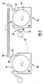
- Fig.1 illustrates a schematic view of a known method for electroplating a strip of as e.g. described in US 4,326,931.
- a rotary drum 10 which represents a moving cathode, is immersed in an electroplating bath 12 and rotated by driving means (not shown) at a constant speed. Electric current is supplied through a slip ring 14 mounted on a drum shaft 16 so that a predetermined voltage will be applied between the rotary drum 10 and a cylindrically shaped anode 18 positioned in the vicinity of the drum 10.
- a strip of foam 20 having an electrically conductive surface and two opposite sides 22, 22' is continuously applied onto the drum 10 so that it travels through the bath 12 in contact with the drum 10.
- the strip 20 runs at the same speed as the drum 10 while being electroplated.
- the strip 20 has been plated with metal to the desired thickness, it is continuously removed from the cathode drum 10.
- the strip 20 is applied with a first side 22 onto an electrically conductive working surface 24 of the rotary drum 10, which is formed by the outer periphery of the drum 10.
- the strip of foam 20 is continuously, supported by the cathode drum 10 during the electroplating.
- the strip of foam 20 does not oscillate during the plating and the anode/cathode distance remains constant, whereby a uniform plating is achieved.
- the part of the strip of foam 20 being electroplated is in direct contact with the cathode and there are no such power losses as in vertical cells where the current has to travel through the strip from the emerged cathode roll to the electroplating zone.
- a uniform and in-depth plating e.g. up'to half the thickness of the strip, is achieved, thereby obtaining an electroplated strip of foam 20 with an improved plating.
- the electroplated strip of foam 20 obtained with the method shown in Fig.1 is mainly plated on the second side 22', i.e. the side which was facing the anode 18.
- the electroplated strip of foam 20 removed from the drum should thus advantageously be guided to another plating bath with an immersed cathode drum so as to be electroplated in equivalent conditions, however with its second side 22' applied onto the drum.
- Fig.2 Such a method comprising two successive electroplating cells is illustrated in Fig.2, where the two cylindrical plating cells 26 and 28 are equivalent to the cylindrical cell of Fig.1.
- the strip of foam 20 to be electroplated is continuously delivered from a feed roll 30 and makes a downward turn around an idle roll 32 before being applied onto a rotary drum 34 immersed in the plating bath 36 of the first cell 26.
- the first side 22 of the strip 20 faces the drum 34 and is uniformly plated with metal on its opposed, second side 22'.
- the strip is directed to the second plating cell 28.
- the strip 20 is guided around different idle rolls 40 in such a way that the strip 20 can be applied with its second face 22', i.e.
- the electroplated strip of foam 20 exiting the second cell 28 has a uniform plating on both sides and through the whole thickness of the strip. Electroplating in such cylindrical cells allows to achieve the desired plating thickness on the strip of foam, and does not need to be completed by a further electroplating in planar cells.
- the foam is generally a porous substrate with low conductivity made of a variety of organic or non-organic materials, which will be detailed later. Due to the porosity of the foam, some metal deposits may form on the working surface of the moving cathode. Such metal deposits not only waste the electroplating metal but also impair the smoothness of the cathode working surface and are thus considered as parasitic. To remove these parasitic metal deposits, the working surface should be continuously cleaned after the electroplated strip of foam has been removed, for example by means of adapted brushes.
- the present invention provides in its following preferred embodiment a solution for keeping the working surface of a moving cathode in good condition, while being immersed in an electroplating bath.
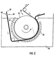
- a preferred embodiment of the present method is schematically illustrated in Fig.3.
- a rotary drum 50 having an electrically conductive working surface 52 and representing a moving cathode is immersed in an electroplating bath 54, thereby forming a cylindrical electroplating cell.
- An anode 56 having a cylindrical shape is located in the vicinity of the cathode drum 50 and a predetermined voltage is applied between the cathode drum 50 and the anode 56.
- Reference sign 58 indicates a strip of foam to be electroplated in the cylindrical cell of Fig.3, the strip of foam 58 having two opposite sides 60 and 60' and an electrically conductive surface.
- a metal foil is advantageously continuously formed on the working surface 52 before applying the strip 58 onto the drum 50.
- This metal foil which is indicated by reference sign 62, is formed in a conventional way between the anode 56 and the rotary cathode drum 50. As the drum 50 rotates, the metal foil 62 becomes thicker. When a predetermined thickness of the metal foil 62 has been reached, the strip of foam 58 is applied with its first side 60 onto the rotary drum 50, over the metal foil 62. As soon as the strip of foam 58 is in contact with the metal foil 62, the plating of the strip of foam 58 takes places.
- the metal foil 62 underlying the strip of foam 58 applied on the cathode drum 50 provides a smooth surface with a good cathodic contact for the plating of the strip of foam 58, while protecting the working surface 52 of the cathode drum 50. Indeed, the parasitic metal deposits will form on the metal foil 62 and not on the working surface 52 as it is not exposed during the plating of the strip of foam 58. Then, when the desired metal plating thickness on the strip of foam 58 has been reached, the latter is removed from the drum 50. The metal foil 62 is then removed from the working surface 52.
- the electroplating bath 54 preferably is a copper sulfate electroplating bath.
- the metal foil 62 will thus be a copper foil, which can be grown to a thickness of e.g. up to 20 ⁇ m.
- a copper foil offers a smooth surface with a good cathodic contact for the plating of the strip of foam 58.
- the removal of the copper foil 62 from the cathode drum is very simple, as it suffices to peel it off.
- the working surface 52 is thus effectively protected during the plating.
- the different operating parameters such as e.g.
- the speed of the drum, the currents, the position where the strip of foam is applied onto the drum should be determined in such a way as to minimize the thickness of the copper foil and to achieve the desired plating thickness of the strip of foam 58.
- the main requirements for the copper foil 62 is that it should be continuous and resist to the mechanical solicitations that are imposed while travelling through the electroplating cell.
- a lack of ions occurs at the side of the strip facing the cathode drum 50, i.e. the first side 60 of the strip 58.
- the electroplated strip of foam 58 issuing from the cylindrical cell of Fig.3 should thus advantageously be guided to an equivalent plating cell, to be plated with its already plated second side 60' applied onto the cathode drum i.e. in contact with the metal foil covering the cathode drum.
- the foam is generally a porous substrate made of organic or in-organic open-cellular materials and generally has a relatively low electrical conductivity. Included are polymeric foams, carbon or graphite foams, silicate foams, synthetic or natural fibers etc... If needed, a foam having a too low conductivity can be made conductive by employing any of a number of well known techniques such as electroless plating with a metal, coating with a conductive paint containing carbon powder or a metal powder, vacuum deposition of a metal (e.g. sputtering), or chemical vapor deposition.
- conductive polymers will be preferably used to make strips of foam conductive.
- the main steps of this technique which is described in EP-A-0 761 710, are the following:
- Suitable monomers for this technique are pyrrole, furan, thiophene or some of their derivatives.
- a preferred monomer is pyrrole, which can be polymerized into polypyrrole.
- the pre-oxidation of the strip of foam is preferably carried out by immersing of the strip of foam into a potassium permanganate bath.
- PVD physical vapor deposition
- the strip of foam is preferably pre-coated with a very thin layer of copper deposited by PVD.
- the latter should advantageously be cathodically polarised prior to entering the electroplating bath so as to prevent the dissolution of the metal pre-coating.
Landscapes
- Chemical & Material Sciences (AREA)
- Engineering & Computer Science (AREA)
- Chemical Kinetics & Catalysis (AREA)
- Electrochemistry (AREA)
- Materials Engineering (AREA)
- Metallurgy (AREA)
- Organic Chemistry (AREA)
- Electroplating Methods And Accessories (AREA)
- Battery Electrode And Active Subsutance (AREA)
- Adhesives Or Adhesive Processes (AREA)
- Treatments Of Macromolecular Shaped Articles (AREA)
Applications Claiming Priority (3)
| Application Number | Priority Date | Filing Date | Title |
|---|---|---|---|
| LU90640A LU90640B1 (en) | 2000-09-18 | 2000-09-18 | Method for electroplating a strip of foam |
| LU90640 | 2000-09-18 | ||
| PCT/EP2001/010517 WO2002022914A1 (en) | 2000-09-18 | 2001-09-12 | Method for electroplating a strip of foam |
Publications (2)
| Publication Number | Publication Date |
|---|---|
| EP1325176A1 EP1325176A1 (en) | 2003-07-09 |
| EP1325176B1 true EP1325176B1 (en) | 2004-05-19 |
Family
ID=19731931
Family Applications (1)
| Application Number | Title | Priority Date | Filing Date |
|---|---|---|---|
| EP01963004A Expired - Lifetime EP1325176B1 (en) | 2000-09-18 | 2001-09-12 | Method for electroplating a strip of foam |
Country Status (10)
Families Citing this family (20)
| Publication number | Priority date | Publication date | Assignee | Title |
|---|---|---|---|---|
| DE10238284B4 (de) * | 2002-08-21 | 2004-11-18 | Infineon Technologies Ag | Verfahren zum Herstellen einer schaumförmigen Metallstruktur, Metallschaum sowie Anordnung aus einem Trägersubstrat und einem Metallschaum |
| EP1477578A1 (en) * | 2003-05-15 | 2004-11-17 | Efoam S.A. | Method for producing a metal coated heavy metal foam |
| US8110076B2 (en) * | 2006-04-20 | 2012-02-07 | Inco Limited | Apparatus and foam electroplating process |
| JP5488996B2 (ja) * | 2010-06-08 | 2014-05-14 | 住友電気工業株式会社 | アルミニウム構造体の製造方法およびアルミニウム構造体 |
| CA2784182A1 (en) * | 2010-05-12 | 2011-11-17 | Sumitomo Electric Industries, Ltd. | Method for producing aluminum structural body and aluminum stuctural body |
| JP5488994B2 (ja) * | 2010-05-12 | 2014-05-14 | 住友電気工業株式会社 | アルミニウム構造体の製造方法およびアルミニウム構造体 |
| JP2011236476A (ja) * | 2010-05-12 | 2011-11-24 | Sumitomo Electric Ind Ltd | アルミニウム構造体の製造方法およびアルミニウム構造体 |
| DE112011103087T5 (de) * | 2010-09-15 | 2013-10-24 | Sumitomo Electric Industries, Ltd. | Verfahren zur Herstellung einer Aluminiumstruktur und Aluminiumstruktur |
| JP2012172220A (ja) * | 2011-02-23 | 2012-09-10 | Sumitomo Electric Ind Ltd | めっき装置およびめっき方法 |
| JP2012219372A (ja) * | 2011-04-14 | 2012-11-12 | Sumitomo Electric Ind Ltd | アルミニウム多孔体の製造方法 |
| JP5680491B2 (ja) * | 2011-06-22 | 2015-03-04 | 住友電気工業株式会社 | ドラム電極及びその製造方法 |
| JP2015137373A (ja) * | 2014-01-21 | 2015-07-30 | 住友電気工業株式会社 | アルミニウム膜の製造方法及び製造装置 |
| CN105088296B (zh) * | 2015-08-26 | 2018-01-02 | 深圳市深联发科技有限公司 | 泡沫金属的电镀工艺 |
| US10858748B2 (en) | 2017-06-30 | 2020-12-08 | Apollo Energy Systems, Inc. | Method of manufacturing hybrid metal foams |
| KR102273727B1 (ko) * | 2017-11-09 | 2021-07-05 | 주식회사 엘지에너지솔루션 | 전해 동박 제조 장치 |
| CN110724975B (zh) * | 2019-11-15 | 2025-03-07 | 清华大学 | 一种连续电化学沉积制备金属颗粒的装置 |
| CN113249770A (zh) * | 2021-06-07 | 2021-08-13 | 重庆金美新材料科技有限公司 | 一种用于柔性薄膜基材表面电镀加工的水电镀设备 |
| CN113913903B (zh) * | 2021-09-29 | 2023-04-28 | 重庆金美新材料科技有限公司 | 一种电镀装置和电镀方法 |
| CN115717255B (zh) * | 2022-11-29 | 2025-07-25 | 浙江工业大学 | 一种零应力电解金属箔制备法,及其所用的系统和方法的应用 |
| CN117144452B (zh) * | 2023-10-07 | 2024-08-09 | 广东捷盟智能装备股份有限公司 | 一种去除导电辊长铜的电镀机构 |
Family Cites Families (20)
| Publication number | Priority date | Publication date | Assignee | Title |
|---|---|---|---|---|
| US1750831A (en) * | 1927-03-05 | 1930-03-18 | Cairns Dev Company | Art of making metal fabrics |
| US3362893A (en) * | 1964-04-27 | 1968-01-09 | Ibm | Method and apparatus for the high speed production of magnetic films |
| JPS53128544A (en) * | 1977-04-15 | 1978-11-09 | Sumitomo Electric Ind Ltd | Continuous method of preventing corrosion of metallic porous structure |
| US4326931A (en) * | 1978-10-12 | 1982-04-27 | Sumitomo Electric Industries, Ltd. | Process for continuous production of porous metal |
| US4328931A (en) * | 1980-03-10 | 1982-05-11 | Scott Paper Company | Automatic speed control of a rewinder |
| JPS61207593A (ja) * | 1985-03-09 | 1986-09-13 | Sumitomo Electric Ind Ltd | 金属多孔体の製造方法 |
| JPH0723553B2 (ja) * | 1986-10-02 | 1995-03-15 | 住友電気工業株式会社 | 三次元網状構造体のメッキ方法 |
| US4892626A (en) * | 1988-01-21 | 1990-01-09 | Boeing Company | Method for plating one side of a woven fabric sheet |
| JP2628600B2 (ja) * | 1988-04-05 | 1997-07-09 | 住友電気工業株式会社 | 金属多孔体の製造方法 |
| JPH02274895A (ja) * | 1989-04-14 | 1990-11-09 | Katayama Tokushu Kogyo Kk | 金属多孔体及びその製造方法 |
| JPH07116635B2 (ja) * | 1989-10-16 | 1995-12-13 | 片山特殊工業株式会社 | 電池電極板用金属多孔体の製造方法および該方法により製造された電池電極板用金属多孔体 |
| JPH0734299A (ja) * | 1993-07-16 | 1995-02-03 | Fuji Photo Film Co Ltd | 金属製帯状支持体への給電装置 |
| JPH0754196A (ja) * | 1993-08-13 | 1995-02-28 | Mitsubishi Rayon Co Ltd | 金属膜積層高分子フィルム複合膜の製造装置および製造方法 |
| JPH08225989A (ja) * | 1995-02-22 | 1996-09-03 | Achilles Corp | 金属多孔体の製造方法とその装置 |
| JPH08269783A (ja) * | 1995-03-29 | 1996-10-15 | Achilles Corp | 電着方法とその装置 |
| JPH08333696A (ja) * | 1995-06-07 | 1996-12-17 | Achilles Corp | 金属多孔体の製造方法とその装置 |
| FR2737507B1 (fr) * | 1995-08-04 | 1997-09-26 | Scps | Structures poreuses complexes metallisees ou metalliques, premetallisees par depot d'un polymere conducteur |
| FR2776211B1 (fr) * | 1998-03-19 | 2000-07-13 | Scps | Structures poreuses complexes epaisses rendues electriquement conductrices, et procede d'activation conductrice correspondant |
| DE19842974A1 (de) * | 1998-09-19 | 2000-03-23 | Schmid Gmbh & Co Geb | Einrichtung zur Behandlung von Gegenständen, insbesondere Galvanisiereinrichtung für Leiterplatten |
| US6471846B1 (en) * | 1998-09-25 | 2002-10-29 | Kazuo Ohba | Electric feeding method and apparatus for a continuous plating apparatus |
-
2000
- 2000-09-18 LU LU90640A patent/LU90640B1/en active
-
2001
- 2001-09-11 TW TW90122441A patent/TW575692B/zh not_active IP Right Cessation
- 2001-09-12 CN CNB018158366A patent/CN1240881C/zh not_active Expired - Lifetime
- 2001-09-12 US US10/380,816 patent/US6942781B2/en not_active Expired - Lifetime
- 2001-09-12 JP JP2002527348A patent/JP4565806B2/ja not_active Expired - Lifetime
- 2001-09-12 AU AU2001284059A patent/AU2001284059A1/en not_active Abandoned
- 2001-09-12 EP EP01963004A patent/EP1325176B1/en not_active Expired - Lifetime
- 2001-09-12 AT AT01963004T patent/ATE267279T1/de not_active IP Right Cessation
- 2001-09-12 WO PCT/EP2001/010517 patent/WO2002022914A1/en active IP Right Grant
- 2001-09-12 DE DE60103419T patent/DE60103419T2/de not_active Expired - Lifetime
Also Published As
| Publication number | Publication date |
|---|---|
| LU90640B1 (en) | 2002-05-23 |
| CN1240881C (zh) | 2006-02-08 |
| US20030188973A1 (en) | 2003-10-09 |
| CN1458987A (zh) | 2003-11-26 |
| TW575692B (en) | 2004-02-11 |
| JP4565806B2 (ja) | 2010-10-20 |
| DE60103419T2 (de) | 2005-08-11 |
| WO2002022914A1 (en) | 2002-03-21 |
| JP2004509230A (ja) | 2004-03-25 |
| DE60103419D1 (de) | 2004-06-24 |
| EP1325176A1 (en) | 2003-07-09 |
| ATE267279T1 (de) | 2004-06-15 |
| AU2001284059A1 (en) | 2002-03-26 |
| US6942781B2 (en) | 2005-09-13 |
Similar Documents
| Publication | Publication Date | Title |
|---|---|---|
| EP1325176B1 (en) | Method for electroplating a strip of foam | |
| US4824746A (en) | Thin electrode supported on electronically conductive sheet and process of manufacture | |
| JP3174047B2 (ja) | 導電性発泡体の連続的電気メッキ法 | |
| JP3450333B2 (ja) | 連続的にむらなく電解金属化乃至エッチングするための方法及び装置 | |
| US4326931A (en) | Process for continuous production of porous metal | |
| CN118685827B (zh) | 一种一体式载体铜箔生产设备 | |
| US20150211143A1 (en) | Aluminum plating apparatus and method for producing aluminum film using same | |
| US4176035A (en) | Installation for the production of a copper foil intended to be applied to a dielectric substrate | |
| US5098544A (en) | Continuous electroplating of conductive foams | |
| US4692221A (en) | In-situ dendritic treatment of electrodeposited foil | |
| US3374159A (en) | Marking of steel strip electrolytically using electrolyte adhering to the strip | |
| KR102463038B1 (ko) | 전해 동박 제조 장치 | |
| JP2628600B2 (ja) | 金属多孔体の製造方法 | |
| CN115029739A (zh) | 新型铜箔制造方法 | |
| JPS6389697A (ja) | 三次元網状構造体のメッキ方法 | |
| US1379089A (en) | Production of thin metallic sheets or foils | |
| KR100350064B1 (ko) | 표면외관이우수한전기아연도금강판의제조방법 | |
| JPH08333696A (ja) | 金属多孔体の製造方法とその装置 | |
| KR20010059601A (ko) | 에지부 도금층이 균일한 전기도금방법 | |
| JPS61207593A (ja) | 金属多孔体の製造方法 | |
| JPH01502204A (ja) | 電着による極薄金属薄板の連続製造設備 | |
| CN222948498U (zh) | 一种hjt晶硅电池电镀与退镀一体化设备 | |
| CN113529140B (zh) | 一种新型电解铜箔生产方法 | |
| US5000833A (en) | Apparatus for the electrochemical surface treatment of substrates | |
| JP2567537B2 (ja) | 金属箔電解製造装置 |
Legal Events
| Date | Code | Title | Description |
|---|---|---|---|
| PUAI | Public reference made under article 153(3) epc to a published international application that has entered the european phase |
Free format text: ORIGINAL CODE: 0009012 |
|
| 17P | Request for examination filed |
Effective date: 20030310 |
|
| AK | Designated contracting states |
Designated state(s): AT BE CH CY DE DK ES FI FR GB GR IE IT LI LU MC NL PT SE TR |
|
| AX | Request for extension of the european patent |
Extension state: AL LT LV MK RO SI |
|
| GRAP | Despatch of communication of intention to grant a patent |
Free format text: ORIGINAL CODE: EPIDOSNIGR1 |
|
| RAP1 | Party data changed (applicant data changed or rights of an application transferred) |
Owner name: CIRCUIT FOIL LUXEMBOURG S.A.R.L. |
|
| RAP1 | Party data changed (applicant data changed or rights of an application transferred) |
Owner name: EFOAM S.A. |
|
| GRAS | Grant fee paid |
Free format text: ORIGINAL CODE: EPIDOSNIGR3 |
|
| GRAA | (expected) grant |
Free format text: ORIGINAL CODE: 0009210 |
|
| AK | Designated contracting states |
Kind code of ref document: B1 Designated state(s): AT BE CH CY DE DK ES FI FR GB GR IE IT LI LU MC NL PT SE TR |
|
| PG25 | Lapsed in a contracting state [announced via postgrant information from national office to epo] |
Ref country code: IT Free format text: LAPSE BECAUSE OF FAILURE TO SUBMIT A TRANSLATION OF THE DESCRIPTION OR TO PAY THE FEE WITHIN THE PRESCRIBED TIME-LIMIT;WARNING: LAPSES OF ITALIAN PATENTS WITH EFFECTIVE DATE BEFORE 2007 MAY HAVE OCCURRED AT ANY TIME BEFORE 2007. THE CORRECT EFFECTIVE DATE MAY BE DIFFERENT FROM THE ONE RECORDED. Effective date: 20040519 Ref country code: NL Free format text: LAPSE BECAUSE OF FAILURE TO SUBMIT A TRANSLATION OF THE DESCRIPTION OR TO PAY THE FEE WITHIN THE PRESCRIBED TIME-LIMIT Effective date: 20040519 Ref country code: TR Free format text: LAPSE BECAUSE OF FAILURE TO SUBMIT A TRANSLATION OF THE DESCRIPTION OR TO PAY THE FEE WITHIN THE PRESCRIBED TIME-LIMIT Effective date: 20040519 Ref country code: CY Free format text: LAPSE BECAUSE OF FAILURE TO SUBMIT A TRANSLATION OF THE DESCRIPTION OR TO PAY THE FEE WITHIN THE PRESCRIBED TIME-LIMIT Effective date: 20040519 Ref country code: CH Free format text: LAPSE BECAUSE OF FAILURE TO SUBMIT A TRANSLATION OF THE DESCRIPTION OR TO PAY THE FEE WITHIN THE PRESCRIBED TIME-LIMIT Effective date: 20040519 Ref country code: AT Free format text: LAPSE BECAUSE OF FAILURE TO SUBMIT A TRANSLATION OF THE DESCRIPTION OR TO PAY THE FEE WITHIN THE PRESCRIBED TIME-LIMIT Effective date: 20040519 Ref country code: FI Free format text: LAPSE BECAUSE OF FAILURE TO SUBMIT A TRANSLATION OF THE DESCRIPTION OR TO PAY THE FEE WITHIN THE PRESCRIBED TIME-LIMIT Effective date: 20040519 Ref country code: LI Free format text: LAPSE BECAUSE OF FAILURE TO SUBMIT A TRANSLATION OF THE DESCRIPTION OR TO PAY THE FEE WITHIN THE PRESCRIBED TIME-LIMIT Effective date: 20040519 |
|
| REG | Reference to a national code |
Ref country code: GB Ref legal event code: FG4D |
|
| REG | Reference to a national code |
Ref country code: CH Ref legal event code: EP |
|
| REG | Reference to a national code |
Ref country code: IE Ref legal event code: FG4D |
|
| REF | Corresponds to: |
Ref document number: 60103419 Country of ref document: DE Date of ref document: 20040624 Kind code of ref document: P |
|
| PG25 | Lapsed in a contracting state [announced via postgrant information from national office to epo] |
Ref country code: SE Free format text: LAPSE BECAUSE OF FAILURE TO SUBMIT A TRANSLATION OF THE DESCRIPTION OR TO PAY THE FEE WITHIN THE PRESCRIBED TIME-LIMIT Effective date: 20040819 Ref country code: DK Free format text: LAPSE BECAUSE OF FAILURE TO SUBMIT A TRANSLATION OF THE DESCRIPTION OR TO PAY THE FEE WITHIN THE PRESCRIBED TIME-LIMIT Effective date: 20040819 Ref country code: GR Free format text: LAPSE BECAUSE OF FAILURE TO SUBMIT A TRANSLATION OF THE DESCRIPTION OR TO PAY THE FEE WITHIN THE PRESCRIBED TIME-LIMIT Effective date: 20040819 |
|
| PG25 | Lapsed in a contracting state [announced via postgrant information from national office to epo] |
Ref country code: ES Free format text: LAPSE BECAUSE OF FAILURE TO SUBMIT A TRANSLATION OF THE DESCRIPTION OR TO PAY THE FEE WITHIN THE PRESCRIBED TIME-LIMIT Effective date: 20040830 |
|
| PG25 | Lapsed in a contracting state [announced via postgrant information from national office to epo] |
Ref country code: LU Free format text: LAPSE BECAUSE OF NON-PAYMENT OF DUE FEES Effective date: 20040912 |
|
| PG25 | Lapsed in a contracting state [announced via postgrant information from national office to epo] |
Ref country code: IE Free format text: LAPSE BECAUSE OF NON-PAYMENT OF DUE FEES Effective date: 20040913 |
|
| PG25 | Lapsed in a contracting state [announced via postgrant information from national office to epo] |
Ref country code: MC Free format text: LAPSE BECAUSE OF NON-PAYMENT OF DUE FEES Effective date: 20040930 |
|
| LTIE | Lt: invalidation of european patent or patent extension |
Effective date: 20040519 |
|
| NLV1 | Nl: lapsed or annulled due to failure to fulfill the requirements of art. 29p and 29m of the patents act | ||
| REG | Reference to a national code |
Ref country code: CH Ref legal event code: PL |
|
| ET | Fr: translation filed | ||
| PLBE | No opposition filed within time limit |
Free format text: ORIGINAL CODE: 0009261 |
|
| STAA | Information on the status of an ep patent application or granted ep patent |
Free format text: STATUS: NO OPPOSITION FILED WITHIN TIME LIMIT |
|
| 26N | No opposition filed |
Effective date: 20050222 |
|
| REG | Reference to a national code |
Ref country code: IE Ref legal event code: MM4A |
|
| PG25 | Lapsed in a contracting state [announced via postgrant information from national office to epo] |
Ref country code: PT Free format text: LAPSE BECAUSE OF NON-PAYMENT OF DUE FEES Effective date: 20041019 |
|
| REG | Reference to a national code |
Ref country code: GB Ref legal event code: 732E Free format text: REGISTERED BETWEEN 20101028 AND 20101103 |
|
| REG | Reference to a national code |
Ref country code: FR Ref legal event code: TP |
|
| REG | Reference to a national code |
Ref country code: DE Ref legal event code: R082 Ref document number: 60103419 Country of ref document: DE Representative=s name: OFFICE ERNEST T. FREYLINGER S.A., LU |
|
| REG | Reference to a national code |
Ref country code: DE Ref legal event code: R082 Ref document number: 60103419 Country of ref document: DE Representative=s name: OFFICE FREYLINGER S.A., LU Effective date: 20110722 Ref country code: DE Ref legal event code: R081 Ref document number: 60103419 Country of ref document: DE Owner name: CIRCUIT FOIL LUXEMBOURG, LU Free format text: FORMER OWNER: EFOAM S.A., LUXEMBURG/LUXEMBOURG, LU Effective date: 20110722 |
|
| REG | Reference to a national code |
Ref country code: FR Ref legal event code: PLFP Year of fee payment: 16 |
|
| REG | Reference to a national code |
Ref country code: FR Ref legal event code: PLFP Year of fee payment: 17 |
|
| REG | Reference to a national code |
Ref country code: FR Ref legal event code: PLFP Year of fee payment: 18 |
|
| PGFP | Annual fee paid to national office [announced via postgrant information from national office to epo] |
Ref country code: DE Payment date: 20200914 Year of fee payment: 20 Ref country code: FR Payment date: 20200915 Year of fee payment: 20 Ref country code: GB Payment date: 20200914 Year of fee payment: 20 |
|
| PGFP | Annual fee paid to national office [announced via postgrant information from national office to epo] |
Ref country code: BE Payment date: 20200915 Year of fee payment: 20 |
|
| REG | Reference to a national code |
Ref country code: DE Ref legal event code: R071 Ref document number: 60103419 Country of ref document: DE |
|
| REG | Reference to a national code |
Ref country code: BE Ref legal event code: MK Effective date: 20210912 Ref country code: GB Ref legal event code: PE20 Expiry date: 20210911 |
|
| PG25 | Lapsed in a contracting state [announced via postgrant information from national office to epo] |
Ref country code: GB Free format text: LAPSE BECAUSE OF EXPIRATION OF PROTECTION Effective date: 20210911 |