EP1319867A2 - Einrichtung zum Anfahren eines mit einer Automatikgetriebeanordnung ausgestatteten Kraftfahrzeugs - Google Patents
Einrichtung zum Anfahren eines mit einer Automatikgetriebeanordnung ausgestatteten Kraftfahrzeugs Download PDFInfo
- Publication number
- EP1319867A2 EP1319867A2 EP02027175A EP02027175A EP1319867A2 EP 1319867 A2 EP1319867 A2 EP 1319867A2 EP 02027175 A EP02027175 A EP 02027175A EP 02027175 A EP02027175 A EP 02027175A EP 1319867 A2 EP1319867 A2 EP 1319867A2
- Authority
- EP
- European Patent Office
- Prior art keywords
- starting
- gear
- brake
- braking force
- automatic transmission
- Prior art date
- Legal status (The legal status is an assumption and is not a legal conclusion. Google has not performed a legal analysis and makes no representation as to the accuracy of the status listed.)
- Withdrawn
Links
Images


Classifications
-
- F—MECHANICAL ENGINEERING; LIGHTING; HEATING; WEAPONS; BLASTING
- F16—ENGINEERING ELEMENTS AND UNITS; GENERAL MEASURES FOR PRODUCING AND MAINTAINING EFFECTIVE FUNCTIONING OF MACHINES OR INSTALLATIONS; THERMAL INSULATION IN GENERAL
- F16H—GEARING
- F16H3/00—Toothed gearings for conveying rotary motion with variable gear ratio or for reversing rotary motion
- F16H3/44—Toothed gearings for conveying rotary motion with variable gear ratio or for reversing rotary motion using gears having orbital motion
- F16H3/62—Gearings having three or more central gears
- F16H3/66—Gearings having three or more central gears composed of a number of gear trains without drive passing from one train to another
- F16H3/666—Gearings having three or more central gears composed of a number of gear trains without drive passing from one train to another with compound planetary gear units, e.g. two intermeshing orbital gears
-
- F—MECHANICAL ENGINEERING; LIGHTING; HEATING; WEAPONS; BLASTING
- F16—ENGINEERING ELEMENTS AND UNITS; GENERAL MEASURES FOR PRODUCING AND MAINTAINING EFFECTIVE FUNCTIONING OF MACHINES OR INSTALLATIONS; THERMAL INSULATION IN GENERAL
- F16H—GEARING
- F16H2200/00—Transmissions for multiple ratios
- F16H2200/003—Transmissions for multiple ratios characterised by the number of forward speeds
- F16H2200/0052—Transmissions for multiple ratios characterised by the number of forward speeds the gear ratios comprising six forward speeds
-
- F—MECHANICAL ENGINEERING; LIGHTING; HEATING; WEAPONS; BLASTING
- F16—ENGINEERING ELEMENTS AND UNITS; GENERAL MEASURES FOR PRODUCING AND MAINTAINING EFFECTIVE FUNCTIONING OF MACHINES OR INSTALLATIONS; THERMAL INSULATION IN GENERAL
- F16H—GEARING
- F16H2200/00—Transmissions for multiple ratios
- F16H2200/20—Transmissions using gears with orbital motion
- F16H2200/2002—Transmissions using gears with orbital motion characterised by the number of sets of orbital gears
- F16H2200/2007—Transmissions using gears with orbital motion characterised by the number of sets of orbital gears with two sets of orbital gears
-
- F—MECHANICAL ENGINEERING; LIGHTING; HEATING; WEAPONS; BLASTING
- F16—ENGINEERING ELEMENTS AND UNITS; GENERAL MEASURES FOR PRODUCING AND MAINTAINING EFFECTIVE FUNCTIONING OF MACHINES OR INSTALLATIONS; THERMAL INSULATION IN GENERAL
- F16H—GEARING
- F16H2200/00—Transmissions for multiple ratios
- F16H2200/20—Transmissions using gears with orbital motion
- F16H2200/2002—Transmissions using gears with orbital motion characterised by the number of sets of orbital gears
- F16H2200/201—Transmissions using gears with orbital motion characterised by the number of sets of orbital gears with three sets of orbital gears
-
- F—MECHANICAL ENGINEERING; LIGHTING; HEATING; WEAPONS; BLASTING
- F16—ENGINEERING ELEMENTS AND UNITS; GENERAL MEASURES FOR PRODUCING AND MAINTAINING EFFECTIVE FUNCTIONING OF MACHINES OR INSTALLATIONS; THERMAL INSULATION IN GENERAL
- F16H—GEARING
- F16H2200/00—Transmissions for multiple ratios
- F16H2200/20—Transmissions using gears with orbital motion
- F16H2200/202—Transmissions using gears with orbital motion characterised by the type of Ravigneaux set
- F16H2200/2023—Transmissions using gears with orbital motion characterised by the type of Ravigneaux set using a Ravigneaux set with 4 connections
-
- F—MECHANICAL ENGINEERING; LIGHTING; HEATING; WEAPONS; BLASTING
- F16—ENGINEERING ELEMENTS AND UNITS; GENERAL MEASURES FOR PRODUCING AND MAINTAINING EFFECTIVE FUNCTIONING OF MACHINES OR INSTALLATIONS; THERMAL INSULATION IN GENERAL
- F16H—GEARING
- F16H2200/00—Transmissions for multiple ratios
- F16H2200/20—Transmissions using gears with orbital motion
- F16H2200/2097—Transmissions using gears with orbital motion comprising an orbital gear set member permanently connected to the housing, e.g. a sun wheel permanently connected to the housing
Definitions
- the invention relates to a device for starting with an automatic transmission arrangement equipped motor vehicle according to the preamble of claim 1.
- the drawing figure 4 shows a transmission diagram of an automatic transmission arrangement according to the prior art with upstream hydrodynamic converter as starting device.
- an automatic transmission arrangement is an automatic one Six-speed gearbox such as the one in translation European patent EP 0 434 525 B1, DE 690 10 472 T2, is described in detail.
- This automatic transmission arrangement as well as those described in this publication Arrangements are subsequently made after the inventor, Pierre Lepelletier, as automatic gearbox arrangements according to Lepelletier named.
- An automatic transmission arrangement 25 after Lepelletier comprises a gear housing 7, in which the items specified below are arranged, namely a drive shaft 1 and a Output shaft 2, a simple input planetary gear 4 and a double output planetary gear 5, three clutches A, B and E and two brakes C and D.
- the input planetary gear 4 is known per se Kind from the sun gear 12, that of the web or planet carrier 15 held planet gear 13 and the ring gear 14.
- the drawing figure 4 one can see that the sun gear 12, the planet gear 13 and the ring gear 14 in pairs in a manner known per se, namely the sun gear 12 with the planet gear 13 as well the planet gear 13 with the ring gear 14 are engaged.
- the output planetary gear 5 is also in itself known way from the sun gear 16, that of the inner web or inner planet carrier 21 held inner planet wheel 17, that held by the outer web or outer planet carrier 22 Outer planet gear 18 and the ring gear 19. Furthermore, in In the present exemplary embodiment, a further sun gear 20 intended.
- the drawing figure 4 also shows that the sun gear 16, the inner planet gear 17, the outer planet gear 18 and the ring gear 19 of the output planetary gear 5 in itself intermesh in a known manner. So the ring gear stands 19 in operative connection with the outer planet wheel 18, the outer wheel 18 in turn is operatively connected to the inner wheel 17 and the inner wheel 17 is in operative engagement with the sun wheel 16.
- FIG. 4 also shows that the sun gear 20 is engaged with the outer planet gear 18.
- the drive shaft 1 is now with the ring gear 14 of the input planetary gear 4 connected.
- the sun gear 12 of the input planetary gear 4 is non-rotatable with the gear housing 7 connected.
- the web 15 is on the one hand via the clutch A connectable to the sun gear 16, on the other hand is also a Connection can be established via clutch B with sun gear 20.
- the two non-rotatably connected webs, inner web 21 and outer web 22, the output planetary gear 5 are on the one hand via the brake D with the gear housing 7 rotatably connectable, on the other hand is a via the coupling E. Connection to drive shaft 1 can be established.
- the sun gear 20 via the clutch B with the web 15 of the To connect input planetary gear 4 there is also the possibility of a non-rotatable connection via brake C. to manufacture with the gear housing 7.
- the drawing figure 4 also shows that the ring gear 19th the output planetary gear 5 rotatably with the output shaft 2 is connected.
- the invention is therefore based on the object of a device for starting one with a between a drive shaft and an output shaft arranged in a gear housing
- the invention is based on the idea of replacing the converter To provide epicyclic gears with at least three wheels, one of which one possibly via further gear stages with the drive shaft and one possibly also with other gear stages the output shaft can be coupled and in which the third wheel a starting brake, the braking force of which can be regulated, with the Transmission housing of the automatic transmission arrangement is connectable.
- the epicyclic gear can preferably be a simple planetary gear with a sun gear, a planet gear and a ring gear be, for example, the ring gear with the drive shaft is coupled, the planet gear via one or more Gear stages can be coupled to the output shaft and that Sun gear via the aforementioned starting brake with the housing is connectable.
- This variant is particularly useful because it is a planetary gear in itself known simple design with a small footprint.
- the epicyclic gear is a component the automatic transmission arrangement.
- the advantage of this Variant is that according to the state of the art a variety of automatic transmission arrangements for speed conversion such epicyclic gears, preferably planetary gear sets, exhibit.
- a wheel of the aforementioned is a component of the automatic transmission existing epicyclic gear is non-rotatably connected to the gear housing. It is therefore easily possible to break the non-rotatable connection and one create adjustable coupling via a starting brake.
- the epicyclic gear at which according to the prior art a wheel rotatably with the Gearbox is connected, an upstream reduction stage or an upstream translation stage of the automatic transmission arrangement is.
- this wheel is now using the aforementioned starting brake connected to the gearbox.
- a device for starting is provided in a known automatic transmission arrangement in Lepelletier construction to implement.
- This variant has the The advantage of having particularly small dimensions.
- Such an automatic transmission arrangement includes - as described in detail above was - an upstream reduction stage 27 in the form of a planetary gear.
- This input planetary gear 4 includes with reference to the preceding description and the drawing figure 4 a sun gear 12, one of the web 15th held planet gear 13 and a ring gear 14.
- This planetary gear is on the input side according to the prior art the hydrodynamic converter 3 or accordingly via the Converter lockup clutch 6 connected to the motor shaft M.
- the sun gear 12 of this input planetary gear 4 is also according to the prior art, non-rotatably with the gear housing 7 connected.
- the starting brake is provided as a friction brake to carry out, whose slip is adjustable.
- the use of a such slip-controlled, friction-based starting clutch in automatic vehicle transmission opens up completely new and comprehensive Possibilities of engine speed adjustment to get out of it Saving fuel without any restrictions in driving performance to have to put up with.
- the idea presented here a functional extension of the Lepelletier automatic transmission arrangement currently meets all requirements to a modern vehicle transmission.
- the braking force of the starting brake is provided to be regulated in such a way that this begins at the start of the start-up procedure is smaller than at the end of the start-up process.
- the braking force is regulated so that it starts at the start of the start essentially disappears, d. H. that the starting brake open at the start of the starting phase, and that the brake locked at the end of the start-up process and thus a non-rotatable connection of the sun gear to the gearbox is made.
- the braking force from the beginning of the Starting process until the end of the starting process essentially continuously increased.
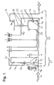
- the input shaft 1 coupled to the engine via the motor shaft M, the output shaft 2 coupled to the output side to the vehicle drive shaft F, the upstream reduction stage 27, which is designed as an input planetary gear 4 with sun gear 12, planet gear 13 and ring gear 14, the output planetary gear 5 with sun gear 16, inner planet gear 17, outer planet gear 18, ring gear 19 and sun gear 20 as well the shifting elements clutch A, clutch B, clutch E, brake C and brake D which can be engaged in pairs to shift the gears.
- starting brake S a slip-controlled, friction-based starting clutch, below referred to as starting brake S to use.
- This starting brake S is used instead of the non-rotatable connection between the gearbox 7 and the sun gear 12 of the input planetary gear 4 arranged and provides an adjustable connection between the Gear housing 7 and this sun gear 12 of the input planetary gear 4.
- the motor shaft M is now no longer via the converter 3 or the converter lock-up clutch 6 with the drive shaft 1 coupled, but it is preferably an immediate Non-rotating or vibration-damping connection of the motor shaft M manufactured with the drive shaft 1.
- the start brake S is opened at the start of the start phase. Due to the rotation of the drive shaft 1 connected to the motor shaft M of the internal combustion engine, the ring gear 14 of the upstream reduction stage 27 designed as an input planetary gear 4 is driven with the motor speed n M. The ring gear speed n 14 is therefore identical to the motor speed n M.
- FIG. 2 now shows a speed translation diagram of FIG Automatic transmission arrangement 26 according to Lepelletier with inventive Device for starting up according to Figure 1 for this State immediately after the start of the starting process.
- the left side of the drawing figure represents this Input planetary gear 4, the right side of the drawing figure 2 the initial planetary gear 5.
- the for graphic determination the speeds of the individual wheels necessary verticals are in the drawing figure corresponding to that in the Drawing figure 1 used reference numerals.
- the input planetary gear designed as a minus gear 4 left line assigned by the reference symbol 12 (sun gear), the middle straight line through the reference number 15 (Web) and the right straight line by reference numeral 14 (ring gear) characterized. Accordingly, they are as a plus gear trained output planetary gear 5 associated straight lines from left to right by reference numerals 21 and 22 (Inner web and outer web), 19 (ring gear) and 16 (sun gear).
- the value of the web speed n 15 results from the intersection of the transmission line 23 determined by the speed n 14 of the ring gear 14 and the speed n 12 of the sun gear 12 with the vertical assigned to the web 15 .
- This land speed n 15 is transmitted to the sun gear 16 of the output planetary gear 5 by means of the closed clutch A.
- the corresponding intersection with the vertical corresponding to the sun gear 16 can also be seen in the drawing figure 2. Since the webs 21 and 22 of the output planetary gear 5 are immobile due to the closed brake B when starting in first gear, the transmission line 24 and thus the ring gear speed n 19 can be determine the output planetary gear 5.
- the ring gear speed n 19 can be read in the drawing figure 2 at the intersection of the transmission line 24 with the vertical corresponding to the ring gear 19.
- the starting brake speed n s drops with increasing driving speed.
- the output speed represented by the vehicle drive shaft speed n F , increases continuously.
- FIG. 3 shows a speed translation diagram of the automatic transmission arrangement according to FIG. 1 with a further increased braking force of the starting brake S, and thus a further reduced starting brake speed n S , which defines the speed n 12 of the sun gear 12.
- the output-side vehicle drive shaft speed n F can be determined in the same way from this diagram.
- the braking of the starting brake S is continued until its speed n s and thus also the sun wheel speed n 12 of the input planetary gear 4 reaches zero speed.
- the land speed n 15 of the input planetary gear 4 thus increases to its maximum value n 15, max . as a fixed relation to the engine speed n M.
- the vehicle input shaft speed n F as the output speed of the automatic transmission 26 reaches the relative value to the engine speed n M corresponding to the gear ratio in first gear.
Abstract
Description
- Figur 1
- ein Getriebeschema einer Automatikgetriebeanordnung eines Kraftfahrzeugs nach Lepelletier mit erfindungs- gemäßer Einrichtung zum Anfahren
- Figur 2
- ein Drehzahl-Übersetzungsdiagramm der Automatikge- triebeanordnung nach Lepelletier mit erfindungsgemä- ßer Einrichtung zum Anfahren gemäß Figur 1 - Zustand unmittelbar nach Beginn des Anfahrvorgangs -
- Figur 3
- ein Drehzahl-Übersetzungsdiagramm der Automatikge- triebeanordnung gemäß Figur 1 - Zustand unmittelbar vor Beendigung des Anfahrvor- gangs -
- Figur 4
- ein Getriebeschema einer Automatikgetriebeanordnung nach Lepelletier mit hydrodynamischem Wandler als An- fahreinrichtung - Stand der Technik -
die vorgelagerte Untersetzungsstufe 27, welche als Eingangsplanetengetriebe 4 mit Sonnenrad 12, Planetenrad 13 und Hohlrad 14 ausgebildet ist,
das Ausgangsplanetengetriebe 5 mit Sonnenrad 16, Innenplanetenrad 17, Außenplanetenrad 18, Hohlrad 19 und Sonnenrad 20 sowie
die zum Schalten der Gänge paarweise in Eingriff verbringbaren Schaltelemente Kupplung A, Kupplung B, Kupplung E, Bremse C und Bremse D.
- 1
- Antriebswelle
- 2
- Abtriebswelle
- 3
- hydrodynamischer Wandler
- 4
- Eingangsplanetengetriebe
- 5
- Ausgangsplanetengetriebe
- 6
- Wandlerüberbrückungskupplung
- 7
- Getriebegehäuse
- 8
- Pumpenrad
- 9
- Turbinenrad
- 10
- Leitrad
- 11
- Freilauf
- 12
- Sonnenrad
- 13
- Planetenrad
- 14
- Hohlrad
- 15
- Steg/Planetenträger
- 16
- Sonnenrad
- 17
- Innenplanetenrad
- 18
- Aussenplanetenrad
- 19
- Hohlrad
- 20
- Sonnenrad
- 21
- Innensteg/Innenplanetenträger
- 22
- Aussensteg/Aussenplanetenträger
- 23
- Übersetzungsgerade
- 24
- Übersetzungsgerade
- 25
- Lepelletier-Automatik-Getriebeanordnung
- 26
- Lepelletier-Automatik-Getriebeanordnung
- 27
- Vorgelagerte Untersetzungsstufe
- A
- Kupplung
- B
- Kupplung
- C
- Bremse
- D
- Bremse
- E
- Kupplung
- F
- Fahrzeugantriebswelle
- M
- Motorwelle
- S
- Anfahrbremse
- ns
- Drehzahl der Anfahrbremse
- nM
- Motordrehzahl
- nF
- Fahrzeugantriebswellendrehzahl
- n12
- Sonnenraddrehzahl
- n14
- Hohlraddrehzahl
- n15
- Stegdrehzahl
- n15,max
- maximale Stegdrehzahl
- n16
- Sonnenraddrehzahl
- n21
- Innenstegdrehzahl
- n22
- Aussenstegdrehzahl
- n19
- Hohlraddrehzahl
- i0
- Standübersetzung
- Ts
- Drehmoment der Anfahrbremse
- TM
- Getriebeeingangsmoment
Claims (15)
- Einrichtung zum Anfahren eines mit einer zwischen einer Antriebswelle (1) und einer Abtriebswelle (2) in einem Getriebegehäuse (7) angeordneten Automatikgetriebeanordnung ausgestatteten Kraftfahrzeuges
mit einem Umlaufgetriebe (4) mit einem ersten mit der Antriebswelle (1) koppelbaren Rad (14), mit einem zweiten mit der Antriebswelle (2) koppelbaren Rad (13, 15) und mit einem dritten Rad (12),
dadurch gekennzeichnet, dass das dritte Rad (12) über eine Anfahrbremse (S), deren Bremskraft regelbar ist, mit dem Getriebegehäuse (7) verbindbar ist. - Einrichtung nach Anspruch 1,
dadurch gekennzeichnet, dass das Umlaufgetriebe ein einfaches Planetenradgetriebe (4) mit einem Sonnenrad (12) mindestens einem Planetenrad (13) und einem Hohlrad (14) ist, wobei das erste Rad das Hohlrad (14), das zweite Rad das Planetenrad (13) und das dritte Rad das Sonnenrad (12) ist. - Einrichtung nach einem der Ansprüche 1 oder 2,
dadurch gekennzeichnet, dass das Umlaufgetriebe (4) Bestandteil der Automatikgetriebeanordnung (26) ist. - Einrichtung nach Anspruch 3, dadurch gekennzeichnet, dass das Umlaufgetriebe (4) eine vorgelagerte Untersetzungsstufe (27) oder eine vorgelagerte Übersetzungsstufe der Automatikgetriebeanordnung (26) ist.
- Einrichtung nach Anspruch 3 oder 4,
dadurch gekennzeichnet, dass die Automatikgetriebeanordnung eine Automatikgetriebeanordnung (26) eines Kraftfahrzeugs nach Lepelletier ist. - Einrichtung nach einem der vorangegangenen Ansprüche,
dadurch gekennzeichnet, dass die Anfahrbremse eine Reibbremse (S) ist, deren Schlupf regelbar ist. - Einrichtung nach einem der vorangegangenen Ansprüche,
dadurch gekennzeichnet, dass die Bremskraft der Anfahrbremse (S) derart regelbar ist, dass die Bremskraft zu Beginn des Anfahrvorgangs kleiner ist als am Ende des Anfahrvorgangs. - Einrichtung nach Anspruch 7,
dadurch gekennzeichnet, dass die Bremskraft der Anfahrbremse (S) derart regelbar ist, dass die Bremskraft zu Beginn des Anfahrvorgangs im Wesentlichen verschwindet und dass die Anfahrtbremse (S) am Ende des Anfahrvorgangs arretiert ist oder auf geringen Schlupf geregelt ist. - Einrichtung nach einem der Ansprüche 7 oder 8,
dadurch gekennzeichnet, dass das Anfahrelement des Getriebes über die Bremskraft der Anfahrbremse (S) derart regelbar ist, dass die Anfahrbeschleunigung vom Beginn des Anfahrvorgangs bis zum Ende des Anfahrvorgangs über einen Regler frei eingestellt werden kann. - Einrichtung nach einem der Ansprüche 7, 8 oder 9
dadurch gekennzeichnet, dass die Bremskraft der Anfahrbremse (S) von außerhalb der Getriebeanordnung regelbar ist. - Automatikgetriebeanordnung (26), mit einer Einrichtung (4, S) nach einem der vorangegangenen Ansprüche.
- Verfahren zum Betreiben einer Einrichtung zum Anfahren nach einem der Ansprüche 1 bis 6,
dadurch gekennzeichnet, dass die Abtriebs-Drehzahl (n19, nF) der Automatikgetriebeanordnung Bremskraft der Anfahrbremse (S) derart geregelt wird, dass die zu Beginn des Anfahrvorgangs kleiner ist als am Ende des Anfahrvorgangs. - Verfahren nach Anspruch 12,
dadurch gekennzeichnet, dass die Bremskraft der Anfahrbremse (S) derart geregelt wird, dass die Bremskraft zu Beginn des Anfahrvorgangs im Wesentlichen verschwindet und dass die Anfahrbremse am Ende des Anfahrvorgangs arretiert ist oder auf einstellbaren Schlupf geregelt ist. - Verfahren nach Anspruch 12 oder 13,
dadurch gekennzeichnet, dass das Anfahrelement des Getriebes über die Bremskraft der Anfahrbremse (S) derart geregelt wird, dass die Anfahrbeschleunigung vom Beginn des Anfahrvorgangs bis zum Ende des Anfahrvorgangs über einen Regler frei eingestellt werden kann. - Verfahren nach einem der Ansprüche 12 bis 14,
dadurch gekennzeichnet, dass die Bemskraft der Anfahrbremse (S) derart geregelt wird, dass die Zunahme der Drehzahl nF der Abtriebswelle (2) einem vorbestimmten Verlauf folgt.
Applications Claiming Priority (2)
| Application Number | Priority Date | Filing Date | Title |
|---|---|---|---|
| DE10161815A DE10161815A1 (de) | 2001-12-14 | 2001-12-14 | Einrichtung zum Anfahren eines mit einer Automatikgetriebeanordnung ausgestatteten Kraftfahrzeugs |
| DE10161815 | 2001-12-14 |
Publications (2)
| Publication Number | Publication Date |
|---|---|
| EP1319867A2 true EP1319867A2 (de) | 2003-06-18 |
| EP1319867A3 EP1319867A3 (de) | 2004-07-14 |
Family
ID=7709444
Family Applications (1)
| Application Number | Title | Priority Date | Filing Date |
|---|---|---|---|
| EP02027175A Withdrawn EP1319867A3 (de) | 2001-12-14 | 2002-12-05 | Einrichtung zum Anfahren eines mit einer Automatikgetriebeanordnung ausgestatteten Kraftfahrzeugs |
Country Status (5)
| Country | Link |
|---|---|
| US (2) | US20030114266A1 (de) |
| EP (1) | EP1319867A3 (de) |
| JP (1) | JP2003222206A (de) |
| KR (1) | KR20030051287A (de) |
| DE (1) | DE10161815A1 (de) |
Cited By (1)
| Publication number | Priority date | Publication date | Assignee | Title |
|---|---|---|---|---|
| CN105840748A (zh) * | 2015-01-15 | 2016-08-10 | 上海通用汽车有限公司 | 自动变速器和车辆 |
Families Citing this family (11)
| Publication number | Priority date | Publication date | Assignee | Title |
|---|---|---|---|---|
| US7235032B2 (en) * | 2005-08-15 | 2007-06-26 | Ford Global Technologies, Llc | Multiple-speed automatic transmission having a two-speed input and a Simpson gearset |
| US7384365B2 (en) * | 2006-01-27 | 2008-06-10 | Gm Global Technology Operations, Inc. | Multi speed transmission |
| US7442145B2 (en) * | 2006-06-02 | 2008-10-28 | Gm Global Technology Operations, Inc. | Multi-Speed transmissions with a long pinion |
| JP4922224B2 (ja) * | 2008-03-27 | 2012-04-25 | 正博 大窪 | 多段自動変速機 |
| JP5324610B2 (ja) | 2011-03-24 | 2013-10-23 | ジヤトコ株式会社 | 自動変速機 |
| CN102287495A (zh) * | 2011-05-31 | 2011-12-21 | 康少松 | 双速行星行走减速机 |
| KR101339247B1 (ko) * | 2011-11-30 | 2014-01-06 | 기아자동차 주식회사 | 하이브리드 자동차의 배터리 충전 방법 및 상기 방법을 사용하는 하이브리드 자동차 |
| DE102013218615A1 (de) * | 2013-09-17 | 2015-03-19 | Zf Friedrichshafen Ag | Lastschaltautomatgetriebe |
| CN104633042A (zh) * | 2014-12-12 | 2015-05-20 | 吴志强 | 一种复合型外壳带侧辅室的液力偶合器以及起动器 |
| CN104976303B (zh) * | 2015-07-07 | 2017-10-03 | 广州市无级制动科技有限责任公司 | 一种复合型箱体式液力偶合器 |
| DE102016211270A1 (de) * | 2016-06-23 | 2017-12-28 | Zf Friedrichshafen Ag | Planetenradsatzsystem für ein Kraftfahrzeuggetriebe, Getriebe für ein Kraftfahrzeug mit einem solchen Planetenradsatzsystem, und Antriebsstrang für ein Kraftfahrzeug |
Family Cites Families (28)
| Publication number | Priority date | Publication date | Assignee | Title |
|---|---|---|---|---|
| US3811343A (en) * | 1969-06-04 | 1974-05-21 | Nissan Motor | Gear train arrangements |
| DE2935361C2 (de) * | 1979-09-01 | 1985-07-18 | Daimler-Benz Ag, 7000 Stuttgart | Automatisches Planetenräder-Gangwechselgetriebe für schwere Kraftfahrzeuge mit einer Dauerbremse |
| DE3144902A1 (de) * | 1981-11-12 | 1983-05-19 | Voith Gmbh J M | "antriebsaggregat mit einem schaltgetriebe" |
| CS271027B1 (en) * | 1988-05-18 | 1990-08-14 | Antonin Ing Csc Hau | Controllable epicyclic gear |
| JPH02236042A (ja) * | 1989-01-23 | 1990-09-18 | Toyota Motor Corp | 自動変速機用歯車変速装置 |
| US5120284A (en) * | 1989-02-03 | 1992-06-09 | Toyota Jidosha Kabushiki Kaisha | Automatic transmission |
| JPH0374665A (ja) * | 1989-03-15 | 1991-03-29 | Toyota Motor Corp | 自動変速機用歯車変速装置 |
| FR2656055B1 (fr) * | 1989-12-18 | 1994-04-29 | Lepelletier Pierre | Transmission automatique multivitesses pour vehicule automobile. |
| FR2693780B1 (fr) * | 1992-07-15 | 1994-09-30 | Lepelletier Pierre | Transmission automatique à cinq vitesses pour voiture particulière. |
| US5437584A (en) * | 1993-04-02 | 1995-08-01 | Ford Motor Company | Two-speed converter |
| US5599251A (en) * | 1995-09-27 | 1997-02-04 | Ford Motor Company | Six speed automatic transmission for automotive vehicles |
| US5707312A (en) * | 1996-04-19 | 1998-01-13 | General Motors Corporation | Multi-speed power transmission |
| DE19625355A1 (de) | 1996-06-25 | 1998-01-02 | Zahnradfabrik Friedrichshafen | Lastschaltgetriebe für Kraftfahrzeuge |
| JP3571858B2 (ja) * | 1996-07-16 | 2004-09-29 | ジヤトコ株式会社 | 自動変速機用歯車変速装置 |
| DE19727153C2 (de) * | 1997-06-26 | 1999-05-20 | Voith Turbo Kg | Mehrganggetriebe, insbesondere Sechsgang-Getriebe |
| DE19739906A1 (de) | 1997-09-11 | 1999-03-18 | Peter Prof Dr Ing Tenberge | Stufenloses Fahrzeuggetriebe |
| DE19817865A1 (de) * | 1998-04-22 | 1999-10-28 | Zahnradfabrik Friedrichshafen | Getriebe mit Retarder |
| WO2000020243A1 (de) * | 1998-10-02 | 2000-04-13 | Luk Lamellen Und Kupplungsbau Gmbh | Getriebe mit zumindest zwei wellen und einer elektromaschine oder einer automatisierten scheibenkupplung |
| JP4144106B2 (ja) * | 1998-12-21 | 2008-09-03 | アイシン・エィ・ダブリュ株式会社 | 車両用自動変速機 |
| DE19909424A1 (de) | 1999-02-23 | 2000-08-24 | Peter Tenberge | Hybridgetriebe für Fahrzeuge |
| DE19912480B4 (de) * | 1999-03-22 | 2006-03-16 | Zf Friedrichshafen Ag | Automatisch schaltbares Kraftfahrzeuggetriebe |
| DE19932613A1 (de) * | 1999-07-13 | 2001-01-18 | Zahnradfabrik Friedrichshafen | Automatgetriebe |
| DE19934696A1 (de) | 1999-07-23 | 2001-05-17 | Zahnradfabrik Friedrichshafen | Elektrodynamisches Antriebssystem |
| US6165097A (en) * | 1999-11-22 | 2000-12-26 | General Motors Corporation | Powertrain with a six speed planetary transmission |
| DE10200379A1 (de) * | 2001-01-09 | 2002-08-01 | Aisin Aw Co | Automatikgetriebe |
| US6422968B1 (en) * | 2001-01-22 | 2002-07-23 | General Motors Corporation | Compact six speed power transmission |
| KR100460859B1 (ko) * | 2001-08-23 | 2004-12-09 | 현대자동차주식회사 | 하이브리드 전기 자동차의 동력전달장치 |
| US6679802B2 (en) * | 2002-02-22 | 2004-01-20 | General Motors Corporation | Family of multi-speed planetary transmission mechanisms having fixed interconnections and six torque-transmitting mechanisms |
-
2001
- 2001-12-14 DE DE10161815A patent/DE10161815A1/de not_active Ceased
-
2002
- 2002-12-05 EP EP02027175A patent/EP1319867A3/de not_active Withdrawn
- 2002-12-13 US US10/318,617 patent/US20030114266A1/en not_active Abandoned
- 2002-12-13 KR KR1020020079414A patent/KR20030051287A/ko not_active Application Discontinuation
- 2002-12-13 JP JP2002361890A patent/JP2003222206A/ja active Pending
-
2005
- 2005-02-10 US US11/054,935 patent/US7267631B2/en not_active Expired - Fee Related
Non-Patent Citations (1)
| Title |
|---|
| TENBERGE P.: "E-AUTOMAT AUTOMATIKGETRIEBE MIT ESPRIT", VDI BERICHTE, no. 1610, 2001, DUESSELDORF, DE, pages 455 - 479, XP008010754 * |
Cited By (2)
| Publication number | Priority date | Publication date | Assignee | Title |
|---|---|---|---|---|
| CN105840748A (zh) * | 2015-01-15 | 2016-08-10 | 上海通用汽车有限公司 | 自动变速器和车辆 |
| CN105840748B (zh) * | 2015-01-15 | 2019-07-02 | 上海通用汽车有限公司 | 自动变速器和车辆 |
Also Published As
| Publication number | Publication date |
|---|---|
| US7267631B2 (en) | 2007-09-11 |
| DE10161815A1 (de) | 2003-06-26 |
| EP1319867A3 (de) | 2004-07-14 |
| US20030114266A1 (en) | 2003-06-19 |
| JP2003222206A (ja) | 2003-08-08 |
| KR20030051287A (ko) | 2003-06-25 |
| US20050137049A1 (en) | 2005-06-23 |
Similar Documents
| Publication | Publication Date | Title |
|---|---|---|
| DE3025349C2 (de) | Untersetzungsgetriebe in Verbindung mit einer Verbrennungsgasturbine, insbesondere für Kraftfahrzeuge | |
| DE19725834B4 (de) | Stufenlos schaltbares automatisches Getriebe für ein Fahrzeug | |
| EP0263856B1 (de) | Stufenloses verzweigungsgetriebe insbesondere für kraftfahrzeuge | |
| DE102008010064B4 (de) | Automatgetriebe mit wenigstens einem Planetensatz | |
| DE19755664C2 (de) | Stufenloses Getriebe für Fahrzeuge | |
| DE3825409C2 (de) | ||
| DE69724082T2 (de) | Automatisches Getriebe | |
| WO2000037829A1 (de) | Stufenlos verstellbares fahrzeuggetriebe | |
| DE19513276B4 (de) | Antriebsstrang für automatische Kraftübertragung bei einem Kraftfahrzeug | |
| DE4010919A1 (de) | Antriebseinrichtung eines fahrzeugs | |
| DE69910641T2 (de) | Kraftübertragungssystem mit zwei einfachen Planetensätzen | |
| DE602005004659T2 (de) | Mehrstufiges automatikgetriebe für personenkraftfahrzeuge oder nutzfahrzeuge | |
| DE10333112A1 (de) | Kraftfahrzeug-Antriebssystem | |
| DE19727153C2 (de) | Mehrganggetriebe, insbesondere Sechsgang-Getriebe | |
| DE2830543A1 (de) | Hydrodynamisch-mechanisches getriebe fuer kraftfahrzeuge | |
| EP0164553B1 (de) | Mehrgängiges, über ein hydraulisches Steuerventilsystem schaltbares, hydrokinetisch-mechanisches Wechselgetriebe für Kraftfahrzeuge | |
| DE2802368C2 (de) | Getriebe | |
| DE2743583A1 (de) | Hydrodynamisch-mechanisches getriebe fuer kraftfahrzeuge | |
| DE3604393A1 (de) | Automatikgetriebe | |
| EP1319867A2 (de) | Einrichtung zum Anfahren eines mit einer Automatikgetriebeanordnung ausgestatteten Kraftfahrzeugs | |
| DE19530486A1 (de) | Automatikgetriebe-Kraftübertragungsstrang für ein Fahrzeug | |
| DE2513570A1 (de) | Wechselgetriebe | |
| DE10250371A1 (de) | Automatikgetriebe | |
| DE102017005310B4 (de) | Gruppengetriebe für ein Kraftfahrzeug, insbesondere für ein Nutzfahrzeug | |
| DE19530488A1 (de) | Automatikgetriebe-Kraftübertragungsstrang für ein Fahrzeug |
Legal Events
| Date | Code | Title | Description |
|---|---|---|---|
| PUAI | Public reference made under article 153(3) epc to a published international application that has entered the european phase |
Free format text: ORIGINAL CODE: 0009012 |
|
| AK | Designated contracting states |
Designated state(s): AT BE BG CH CY CZ DE DK EE ES FI FR GB GR IE IT LI LU MC NL PT SE SI SK TR |
|
| AX | Request for extension of the european patent |
Extension state: AL LT LV MK RO |
|
| PUAL | Search report despatched |
Free format text: ORIGINAL CODE: 0009013 |
|
| AK | Designated contracting states |
Kind code of ref document: A3 Designated state(s): AT BE BG CH CY CZ DE DK EE ES FI FR GB GR IE IT LI LU MC NL PT SE SI SK TR |
|
| AX | Request for extension of the european patent |
Extension state: AL LT LV MK RO |
|
| 17P | Request for examination filed |
Effective date: 20040716 |
|
| AKX | Designation fees paid |
Designated state(s): DE FR GB IT |
|
| RAP1 | Party data changed (applicant data changed or rights of an application transferred) |
Owner name: BORGWARNER INC. |
|
| 17Q | First examination report despatched |
Effective date: 20060328 |
|
| STAA | Information on the status of an ep patent application or granted ep patent |
Free format text: STATUS: THE APPLICATION IS DEEMED TO BE WITHDRAWN |
|
| 18D | Application deemed to be withdrawn |
Effective date: 20080429 |