EP1319615A2 - Anlage zum Beschicken einer Mehrzahl von Verbrauchern mit Pulverförmigen Schüttgut - Google Patents
Anlage zum Beschicken einer Mehrzahl von Verbrauchern mit Pulverförmigen Schüttgut Download PDFInfo
- Publication number
- EP1319615A2 EP1319615A2 EP02027023A EP02027023A EP1319615A2 EP 1319615 A2 EP1319615 A2 EP 1319615A2 EP 02027023 A EP02027023 A EP 02027023A EP 02027023 A EP02027023 A EP 02027023A EP 1319615 A2 EP1319615 A2 EP 1319615A2
- Authority
- EP
- European Patent Office
- Prior art keywords
- valve
- section
- delivery line
- pneumatic
- bulk material
- Prior art date
- Legal status (The legal status is an assumption and is not a legal conclusion. Google has not performed a legal analysis and makes no representation as to the accuracy of the status listed.)
- Granted
Links
Images
Classifications
-
- B—PERFORMING OPERATIONS; TRANSPORTING
- B65—CONVEYING; PACKING; STORING; HANDLING THIN OR FILAMENTARY MATERIAL
- B65G—TRANSPORT OR STORAGE DEVICES, e.g. CONVEYORS FOR LOADING OR TIPPING, SHOP CONVEYOR SYSTEMS OR PNEUMATIC TUBE CONVEYORS
- B65G53/00—Conveying materials in bulk through troughs, pipes or tubes by floating the materials or by flow of gas, liquid or foam
- B65G53/34—Details
- B65G53/52—Adaptations of pipes or tubes
- B65G53/528—Flux combining or dividing arrangements
-
- B—PERFORMING OPERATIONS; TRANSPORTING
- B65—CONVEYING; PACKING; STORING; HANDLING THIN OR FILAMENTARY MATERIAL
- B65G—TRANSPORT OR STORAGE DEVICES, e.g. CONVEYORS FOR LOADING OR TIPPING, SHOP CONVEYOR SYSTEMS OR PNEUMATIC TUBE CONVEYORS
- B65G53/00—Conveying materials in bulk through troughs, pipes or tubes by floating the materials or by flow of gas, liquid or foam
- B65G53/34—Details
- B65G53/52—Adaptations of pipes or tubes
- B65G53/521—Adaptations of pipes or tubes means for preventing the accumulation or for removal of deposits
Definitions
- the invention relates to a system for loading a plurality of Consumers, e.g. B. cells of aluminum melting furnaces with powder Aluminum oxide according to claim 1.
- Consumers e.g. B. cells of aluminum melting furnaces with powder Aluminum oxide according to claim 1.
- a system has become known from EP 0 122 925 in which a storage container, for example for aluminum oxide, connected to a pneumatic conveyor trough is.
- the conveyor trough has a number of side outlets, each with a pneumatic conveyor trough are connected, which in turn has outlets for individual cells in an aluminum melting furnace.
- a system for loading bulk goods containers in which a pneumatic conveying line at intervals with the containers via a Valve arrangement is connected.
- the valve arrangement is such that the valve automatically closes when the level in the container reaches a predetermined value reached.
- the invention has for its object a system for loading a Majority of consumers, e.g. B. of cells of aluminum melting furnaces with to create powdered alumina with the relatively low A large number of cells can be supplied with energy.
- a Majority of consumers e.g. B. of cells of aluminum melting furnaces with to create powdered alumina with the relatively low
- a large number of cells can be supplied with energy.
- Pressure vessel or pump delivery devices for bulk material conveyance are generally known. With the help of these systems bridge a long distance with a relatively low amount of energy. It It is therefore possible to have a large number of removal points, even those located at a distance the material to be conveyed, e.g. B. with alumina.
- the delivery lines in the area to be supplied, e.g. B. the aluminum melting furnaces, so-called template or intermediate container arranged, the Valves are connected to the delivery line.
- the storage container is itself via at least one pneumatic conveyor trough with a plurality of consumers, z. B. connected by cells of the aluminum smelting furnace, the pneumatic conveyor trough has exits per cell of the furnace.
- a pneumatic conveyor trough for conveying bulk material is also known.
- a pipe is also referred to above and below as a conveying trough can be that in the lower area a separate air flow Has channel, the upward-facing boundary is permeable, so that in this way the desired fluidization of the bulk material to be conveyed is achieved becomes.
- the second telescopically cooperating with the first channel section Section can also be designed as a pneumatic conveyor trough by provided with a sieve-like loosening plate and connected to compressed air becomes. In this way it is ensured that problem-free promotion of the Bulk goods until they leave, e.g. B. is secured to the aluminum melting furnace.
- the filling valve between the pneumatic delivery line and the reservoir is controllable. Naturally, it must be prevented that the storage container overfills and possibly causes a jam in the delivery line. thats why According to the invention, a control device is provided for actuating the valve, and the control device is responsive to a level measuring device which determines when the level in the storage container reaches a certain upper value.
- two or more are pneumatic Conveyor troughs are provided for each storage container, preferably on opposite ones Pages, each relating to a consumer arrangement, e.g. B. with an aluminum oven lead a variety of electrolytic cells.
- a monitoring and Indicator device provided for the valves. It determines whether the valve is too is actually closed when the level measuring device or Control device for a corresponding actuation signal for the valve Adjustment has been given in the closed position. Likewise, must be noted whether the valve has been opened after a refilling of the storage container has become necessary.
- valve as a valve member has an axial passage valve ball which is rotatably mounted in a valve housing.
- a flexible sealing ring is arranged and acts on the side of the valve ball facing the delivery line together with the valve ball.
- On the opposite side of the valve ball there is sufficient clearance to the valve housing.
- the valve ball is used, for example, to operate a pneumatic actuator the valve ball is pivoted through an angle of 90 ° from the opening in the closed position and vice versa.
- the internal pressure in the reservoir is lower than the pressurized pneumatic delivery line. In the closed Condition of the valve thus creates a pressure difference on the sealing ring, so that this is inevitably pressed against the surface of the ball.
- the sealing effect increases with increasing pressure difference.
- valve ball is only sealed on one side on the side of the higher pressure. There is no seal on the low pressure side, rather it shows the housing in this area has a large free space in relation to the ball. This creates the necessary forces to open and close the ball reduced a minimum.
- filling valve In particular, no bulk material is deposited in the open position. This increases the operational safety of the valve because the forces required to Switching the valve remain predictable.
- the delivery line on opposite sides of a cylindrical open downward Housing is connected and the valve housing at the bottom of the cylindrical Housing is attached sealingly.
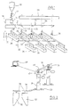
- FIG. 1 shows a storage container 10, for example aluminum oxide powder contains. It is connected via a line 12 which has a sieve and at least contains a shut-off device, which will not be discussed further, to a pressure vessel 14 funded.
- the pressure vessel is connected to a pneumatic delivery line 16 connected.
- the pressure vessel is connected to a compressed air line 18 which is connected to a compressor 20 or to a compressed air network.
- the compressed air line 18 is to the upper end of the pressure vessel 14 and the other led to the lower end, as can be seen in Fig. 1.
- Bulk material here aluminum oxide powder are conveyed through the conveying line 16, and, if necessary, over a relatively large distance without excessive pressure losses and pressure drops arise.
- 16 branch lines 24 are connected to the pneumatic conveying line at intervals, which each lead to a storage container 26.
- To the storage containers 26 are pneumatic conveying troughs at the lower end on opposite sides 28, 30 connected.
- the pneumatic conveyor troughs 28, 30 by a compressor 32 are supplied with compressed air to separate aluminum melting furnaces 34, 36 guided, with one or more outlets for the Conveyor trough 30 are provided, such as shown at 38.
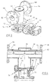
- two storage containers 26 are shown enlarged. It can be seen that in the branch line 24, a valve 40 is arranged, which by a pneumatic Actuator 42 is actuated.
- a fill level measuring device 42 which detects when the level in the container 26 has reached a maximum level. In this case, the valve 40 is then closed. It is opened again when either a predetermined time has passed or when a minimum level in the container 26 has been determined by a further fill level measurement.
- a valve is also assigned to the valves 40, e.g. of Limit switches are formed, as indicated by the dot-dash circle 46. This determines whether an actuation command for valve 40 has been issued the intended position or not, which z. B. with the help of limit switches can be determined. This can be done, for example, by a monitor 48 are displayed.
- FIG. 2 also shows how a conveyor trough 28 with two cells 50, 52 a furnace 36 or 34 is connected.
- the reservoir 26 are connected to an exhaust duct 58 via lines 56.
- the air escaping from the storage container enters this when it be filled via the pneumatic delivery line 16.
- Alumina powder is conveyed in the delivery line 16 during operation and with the valve 42 open into a storage container. Because the consumption of the Aluminum melting furnaces 34, 36, is known, no special regulation is required or Setting for the delivery rates to be set per unit of time. Indeed it is also conceivable to provide a corresponding regulation or to stop the Funding if the relevant circumstances exist.
- a valve 40 is shown in more detail in FIGS. 3 and 4. 3, that the valve is arranged at the lower end of a cylindrical container 60 with which are connected on opposite sides of pipe sections 62, 64, for example by welding. At the ends of the pipe sections 62, 64 there are flanges 66, 68 for connection to the associated end of the delivery line 16 (not shown). On the lower end of the cylindrical container 60 is welded to a flange 70 Connection to the upper flange 72 of the housing 74 of the valve 40.
- the cylindrical valve housing 74 supports a valve ball 76 around a horizontal one Axis.
- the actuation of the valve ball 76 for adjustment by an angle of ⁇ 90 ° takes place through the pneumatic actuating device 42, to which in detail should not be dealt with, since such devices to the state of the Technology belongs.
- a smaller diameter compressed air line 82 is arranged which has incision openings 84 pointing downwards at intervals, in the area of which an aperture 86 is arranged.
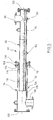
- a conveyor trough which consists of a first tubular gutter section 92 and a second tubular section 94 are assembled is, the latter interacting telescopically with the former.
- the Channel section 92 is over the side nozzle 96 with the reservoir, not shown connected, for example the storage container 26 according to FIGS. 1 and 2. It has an air-permeable channel fabric 98 in the lower region, which at 100 or 102 is connected to compressed air to loosen the material, that enters the channel 90 via the nozzle 96.
- the second section 94 faces an outlet connection 106, which is connected to a cell of an aluminum melting furnace or a further conveyor trough is firmly connected.
- the conveyor trough can thus be adapted to the spatial conditions in the longitudinal direction.
- the tubular portion 94 is provided at one end with a flange 108 which is connected to a ring 110 by screws 112 for the purpose of clamping one Sealing packing 114, which was brought into contact with a ring at 116 on the tube side which is welded to section 94.
- Another ring 118 within the Section 94 serves to guide between sections 92, 94.
- a perforated sheet 120 is shown at 120, whereby a lower channel section 122 is formed, which is provided with a compressed air connection 124 is for loosening the material from the first section 92 in the second section 94 arrives before it falls into the socket 106.
- the end of second section 94 is closed with a blind flange 126.
- the first channel section 92 is also at the right end at 128 with a blind flange sealed off.
Landscapes
- Mechanical Engineering (AREA)
- Engineering & Computer Science (AREA)
- Vertical, Hearth, Or Arc Furnaces (AREA)
- Manufacture And Refinement Of Metals (AREA)
- Filling Or Emptying Of Bunkers, Hoppers, And Tanks (AREA)
- Cultivation Receptacles Or Flower-Pots, Or Pots For Seedlings (AREA)
- Air Transport Of Granular Materials (AREA)
- Feeding, Discharge, Calcimining, Fusing, And Gas-Generation Devices (AREA)
- Furnace Charging Or Discharging (AREA)
- Compositions Of Oxide Ceramics (AREA)
- Vending Machines For Individual Products (AREA)
- Screw Conveyors (AREA)
- Organic Low-Molecular-Weight Compounds And Preparation Thereof (AREA)
Abstract
Description
- Fig. 1
- zeigt schematisch eine Anlage nach der Erfindung.
- Fig. 2
- zeigt eine Einzelheit der Anlage nach der Erfindung.
- Fig. 3
- zeigt perspektivisch ein Füllventil für die Anlage nach Fig. 1.
- Fig. 4
- zeigt einen Schnitt durch das Füllventil nach Fig. 3.
- Fig. 5
- zeigt im Schnitt eine Förderrinne für die Anlage nach Fig. 1.
Claims (9)
- Anlage zum Beschicken einer Mehrzahl von Verbrauchern, z.B. von Zellen von Aluminiumschmelzöfen mit Schüttgut, z.B. pulverförmigem Aluminiumoxid mit
einem Silo (10) für das Schüttgut
einer Druckgefäß- oder Pumpfördervorrichtung (14), die mit
einer Förderleitung (16) verbunden ist
einer Mehrzahl von Vorlagebehältern (26) nahe den Verbrauchern (34, 36), die über Ventile (40) an die Förderleitung (16) angeschlossen sind und mindestens einer pneumatischen Rohr- bzw. Förderrinne (28, 30), die einen Vorlagebehälter (26) mit einer Mehrzahl von Verbrauchern (50, 52) der Öfen (34, 36) verbindet, wobei die Rohr- bzw. Förderrinne (28, 30) mindestens einen Abgang (38) je Verbraucher (50, 52) aufweist. - Anlage nach Anspruch 1, dadurch gekennzeichnet, daß die Vorlagebehälter (26) eine Füllstandsmeßvorrichtung (48) aufweisen, die mit einer Steuervorrichtung für das zugeordnete Ventil (40) verbunden ist und das Ventil (40) schließt, wenn der Füllstand eine vorgegebene Höhe erreicht hat.
- Anlage nach Anspruch 1 oder 2, dadurch gekennzeichnet, daß mindestens zwei pneumatische Rohr- bzw. Förderrinnen (28, 30) mit dem Vorlagebehälter (26) verbunden sind.
- Anlage nach einem der Ansprüche 1 bis 3, dadurch gekennzeichnet, daß eine Überwachungs- und Anzeigevorrichtung (46) für die Füllventile (40) vorgesehen ist, die feststellt und/oder anzeigt, wenn ein Ventil (40) nicht den vorgegebenen Schaltzustand aufweist.
- Anlage nach einem der Ansprüche 1 bis 4, dadurch gekennzeichnet, daß im Gehäuse (74) des Ventils (40) ein Ventilglied von einer einen axialen Durchgang (77) aufweisenden Ventilkugel (76) drehbar gelagert ist, ein elastischer Dichtring (78) auf der der Förderleitung (16) zugewandten Seite der Ventilkugel (76) angeordnet ist und dichtend mit dieser zusammenwirkt, während auf der gegenüberliegenden Seite die Ventilkugel (76) einen Abstand zur Wandung des Ventilgehäuses (74) aufweist.
- Anlage nach Anspruch 5, dadurch gekennzeichnet, daß die Förderleitung (16) an gegenüberliegenden Seiten an einen zylindrischen, nach unten offenen Behälter angeschlossen ist und das Ventilgehäuse (74) am unteren Ende des zylindrischen Behälters (60) angebracht ist.
- Anlage nach einem der Ansprüche 1 bis 6, dadurch gekennzeichnet, daß die Förderrinne (90) einen ersten fest mit dem Vorlagebehälter oder einem Rinnenabschnitt verbindbaren ersten Abschnitt (92) aufweist, und einen zweiten Abschnitt (94), der seitlich mindestens einen Abgang (106) aufweist und teleskopisch mit dem ersten Rinnenabschnitt (92) oder einem weiteren Rinnenabschnitt zusammenwirkt.
- Anlage nach Anspruch 7, dadurch gekennzeichnet, daß der zweite Abschnitt (94) zwischen dem Abgang (106) und dem ersten Abschnitt (92) als pneumatische Förderrinne (120, 124) ausgebildet ist.
- Anlage nach Anspruch 7 oder 8, dadurch gekennzeichnet, daß erster und zweiter Abschnitt (92, 94) als Rohre geformt sind.
Applications Claiming Priority (2)
| Application Number | Priority Date | Filing Date | Title |
|---|---|---|---|
| DE10162398A DE10162398A1 (de) | 2001-12-13 | 2001-12-13 | Anlage zum Beschicken einer Mehrzahl von Verbrauchern, z. B. von Zellen von Aluminiumschmelzöfen mit Schüttgut, z. B. pulverförmigem Aluminiumoxid |
| DE10162398 | 2001-12-13 |
Publications (3)
| Publication Number | Publication Date |
|---|---|
| EP1319615A2 true EP1319615A2 (de) | 2003-06-18 |
| EP1319615A3 EP1319615A3 (de) | 2003-12-10 |
| EP1319615B1 EP1319615B1 (de) | 2004-09-22 |
Family
ID=7709807
Family Applications (1)
| Application Number | Title | Priority Date | Filing Date |
|---|---|---|---|
| EP02027023A Expired - Lifetime EP1319615B1 (de) | 2001-12-13 | 2002-12-03 | Anlage zum Beschicken einer Mehrzahl von Verbrauchern mit Pulverförmigen Schüttgut |
Country Status (15)
| Country | Link |
|---|---|
| US (1) | US6749373B2 (de) |
| EP (1) | EP1319615B1 (de) |
| CN (1) | CN1223501C (de) |
| AT (1) | ATE276950T1 (de) |
| AU (1) | AU2002317516B8 (de) |
| CA (1) | CA2414430C (de) |
| DE (2) | DE10162398A1 (de) |
| DK (1) | DK1319615T3 (de) |
| ES (1) | ES2225718T3 (de) |
| HK (1) | HK1056156A1 (de) |
| NO (1) | NO326869B1 (de) |
| PT (1) | PT1319615E (de) |
| RO (1) | RO121388B1 (de) |
| RU (1) | RU2258024C2 (de) |
| TR (1) | TR200402506T4 (de) |
Cited By (1)
| Publication number | Priority date | Publication date | Assignee | Title |
|---|---|---|---|---|
| EP2757298A1 (de) * | 2013-05-29 | 2014-07-23 | Tata Steel Nederland Technology B.V. | Zuleitung mit teleskopischen Rohrteilen |
Families Citing this family (22)
| Publication number | Priority date | Publication date | Assignee | Title |
|---|---|---|---|---|
| NO315037B1 (no) | 2001-03-21 | 2003-06-30 | Norsk Hydro As | Fremgangsmåte og system for distribusjon av fluidiserbare materialer |
| FR2831528B1 (fr) * | 2001-10-26 | 2004-01-16 | Pechiney Aluminium | Systeme de repartition de matiere pulverulente avec des debits pondereux controles |
| EP1623941A1 (de) * | 2004-08-05 | 2006-02-08 | Alcan Technology & Management Ltd. | Vorrichtung und Verfahren zur pneumatischen Beförderung von Schüttgüten im Dichtstromverfahren |
| CN100420617C (zh) * | 2005-10-12 | 2008-09-24 | 沈阳铝镁设计研究院 | 氧化铝贮仓底部排料结构及排料方法 |
| CN101397681B (zh) * | 2007-09-29 | 2012-05-23 | 沈阳铝镁设计研究院有限公司 | 水平长条型流态化分料装置 |
| LU91376B1 (en) * | 2007-11-16 | 2009-05-18 | Wurth Paul Sa | Injections system for solid particles |
| US8951315B2 (en) * | 2008-11-12 | 2015-02-10 | Exxonmobil Research And Engineering Company | Method of injecting fuel into a gasifier via pressurization |
| FR2952363B1 (fr) * | 2009-11-09 | 2011-11-11 | Alcan Int Ltd | Dispositif a fluidisation potentielle destine au convoyage de materiaux pulverulents en lit hyperdense |
| US8784013B2 (en) * | 2010-01-08 | 2014-07-22 | The Gsi Group, Llc | Pneumatic grain conveying apparatus and method for selectively discharging grain or by-passing the discharge of grain into a grain bin |
| CN102466104B (zh) * | 2010-11-08 | 2015-08-26 | 通用电气公司 | 管道及输送方法 |
| DE102011114171A1 (de) * | 2011-09-19 | 2013-03-21 | Thyssenkrupp Uhde Gmbh | Verfahren zur Herstellung von Synthesegas durch Vergasung einer Biomasse in einer Wirbelschicht |
| CN102327805A (zh) * | 2011-09-30 | 2012-01-25 | 姜本熹 | 一种向磨机加料的方法及装置 |
| FR2980783B1 (fr) * | 2011-10-04 | 2016-05-13 | Rio Tinto Alcan Int Ltd | Procede et dispositif de distribution d'un materiau fluidisable, et installation incluant ledit dispositif |
| RU2506350C1 (ru) * | 2012-08-10 | 2014-02-10 | Общество с ограниченной ответственностью "Объединенная Компания РУСАЛ Инженерно-технологический центр" | Система автоматической подачи сырья в электролизеры с самообжигающимися анодами |
| RU2561940C1 (ru) * | 2014-04-22 | 2015-09-10 | Общество с ограниченной ответственностью "Объединенная Компания РУСАЛ Инженерно-технологический центр" | Система автоматической подачи сырья в электролизеры с самообжигающимися анодами |
| CN105753028B (zh) * | 2016-04-06 | 2017-04-05 | 沈阳鑫博工业技术股份有限公司 | 一种额式吹粉装置及其使用方法 |
| CN107352273A (zh) * | 2017-07-03 | 2017-11-17 | 聊城信源集团有限公司 | 一种氧化铝传输系统及其传输方法 |
| US10421625B2 (en) | 2017-09-08 | 2019-09-24 | Cnh Industrial Canada, Ltd. | System and method for removing blockages present in a delivery conduit of a seeder |
| DE102019001471A1 (de) * | 2019-02-27 | 2020-08-27 | Walter Kramer | Saugfördersystem für Schüttgut, insbesondere Kunststoffgranulat |
| EP3947218A1 (de) * | 2019-04-04 | 2022-02-09 | Reel Alesa AG | Zuführvorrichtung mit präzisionsdurchfluss |
| GB201906310D0 (en) * | 2019-05-03 | 2019-06-19 | Schenck Process Uk Ltd | Material conveying apparatus with shut down valves |
| CN111340387B (zh) * | 2020-03-12 | 2021-02-09 | 李建勋 | 一种粉末冶金生产用质量安全监控管理系统及方法 |
Citations (3)
| Publication number | Priority date | Publication date | Assignee | Title |
|---|---|---|---|---|
| WO1984001560A1 (fr) * | 1982-10-22 | 1984-04-26 | Pechiney Aluminium | Dispositif clos a fluidisation potentielle pour le convoyage horizontal de materiaux pulverulents |
| DE3310452A1 (de) * | 1983-03-23 | 1984-09-27 | Bühler-Miag GmbH, 3300 Braunschweig | Verfahren und vorrichtung zur automatischen pneumatischen beschickung einer vielzahl von verbrauchsstellen mit pulverfoermigem gut |
| US4938848A (en) * | 1989-02-13 | 1990-07-03 | Aluminum Company Of America | Method and apparatus for conveying split streams of alumina powder to an electrolysis cell |
Family Cites Families (13)
| Publication number | Priority date | Publication date | Assignee | Title |
|---|---|---|---|---|
| US3945683A (en) * | 1969-07-09 | 1976-03-23 | Fiber Controls Corporation | Priority interrupt circuit |
| US3753867A (en) * | 1971-04-14 | 1973-08-21 | Koppers Gmbh Heinrich | Apparatus for charging coke ovens |
| US3689045A (en) * | 1971-06-03 | 1972-09-05 | Earl E Coulter | Pulverized fuel delivery system for a blast furnace |
| US4027920A (en) * | 1975-10-14 | 1977-06-07 | The Babcock & Wilcox Company | Distributor |
| DE3042661A1 (de) * | 1980-11-12 | 1982-06-16 | Waeschle Maschinenfabrik Gmbh, 7980 Ravensburg | Verfahren und anlage zur versorgung mehrerer brenner einer feuerungsanlage mit koernigem oder pulverfoermigem brennstoff |
| JPS58104833A (ja) * | 1981-12-12 | 1983-06-22 | Kawasaki Steel Corp | 1個の粉粒体分配輸送タンクから粉粒体を複数供給端に質量流量を任意の設定値に制御して連続供給する方法及びその装置 |
| JPS59124624A (ja) * | 1982-12-27 | 1984-07-18 | Kawasaki Steel Corp | 粉粒体分配輸送方法 |
| NL183951C (nl) * | 1983-01-12 | 1989-03-01 | Hoogovens Groep Bv | Doseerinrichting voor het doseren van poederkool in een luchtleiding naar een hoogoven. |
| FR2562878B2 (fr) * | 1984-04-12 | 1989-06-30 | Pechiney Aluminium | Dispositif clos a fluidisation potentielle pour le convoyage horizontal en lit dense de materiaux pulverulents |
| ES2010672B3 (es) | 1985-10-31 | 1989-12-01 | Alusuisse | Dispositivo para cargar recipientes para material a granel y su utilizacion. |
| DE3603078C1 (de) * | 1986-02-01 | 1987-10-22 | Kuettner Gmbh & Co Kg Dr | Verfahren und Vorrichtung zum dosierten Einfuehren feinkoerniger Feststoffe in einen Industrieofen,insbesondere Hochofen oder Kupolofen |
| US4774893A (en) * | 1987-08-13 | 1988-10-04 | Kinergy Corporation | System of handling refuse derived fuel utilizing same to fire power plants |
| US6332408B2 (en) * | 2000-01-13 | 2001-12-25 | Michael Howlett | Pressure feedback signal to optimise combustion air control |
-
2001
- 2001-12-13 DE DE10162398A patent/DE10162398A1/de not_active Ceased
-
2002
- 2002-12-03 ES ES02027023T patent/ES2225718T3/es not_active Expired - Lifetime
- 2002-12-03 DE DE50201083T patent/DE50201083D1/de not_active Expired - Lifetime
- 2002-12-03 TR TR2004/02506T patent/TR200402506T4/xx unknown
- 2002-12-03 EP EP02027023A patent/EP1319615B1/de not_active Expired - Lifetime
- 2002-12-03 DK DK02027023T patent/DK1319615T3/da active
- 2002-12-03 AT AT02027023T patent/ATE276950T1/de active
- 2002-12-03 PT PT02027023T patent/PT1319615E/pt unknown
- 2002-12-09 RU RU2002132865/02A patent/RU2258024C2/ru active
- 2002-12-10 RO ROA200201580A patent/RO121388B1/ro unknown
- 2002-12-11 AU AU2002317516A patent/AU2002317516B8/en not_active Expired
- 2002-12-11 CA CA002414430A patent/CA2414430C/en not_active Expired - Lifetime
- 2002-12-12 NO NO20025986A patent/NO326869B1/no not_active IP Right Cessation
- 2002-12-13 CN CN02154226.0A patent/CN1223501C/zh not_active Expired - Fee Related
- 2002-12-13 US US10/318,829 patent/US6749373B2/en not_active Expired - Lifetime
-
2003
- 2003-11-19 HK HK03108404A patent/HK1056156A1/xx not_active IP Right Cessation
Patent Citations (3)
| Publication number | Priority date | Publication date | Assignee | Title |
|---|---|---|---|---|
| WO1984001560A1 (fr) * | 1982-10-22 | 1984-04-26 | Pechiney Aluminium | Dispositif clos a fluidisation potentielle pour le convoyage horizontal de materiaux pulverulents |
| DE3310452A1 (de) * | 1983-03-23 | 1984-09-27 | Bühler-Miag GmbH, 3300 Braunschweig | Verfahren und vorrichtung zur automatischen pneumatischen beschickung einer vielzahl von verbrauchsstellen mit pulverfoermigem gut |
| US4938848A (en) * | 1989-02-13 | 1990-07-03 | Aluminum Company Of America | Method and apparatus for conveying split streams of alumina powder to an electrolysis cell |
Cited By (1)
| Publication number | Priority date | Publication date | Assignee | Title |
|---|---|---|---|---|
| EP2757298A1 (de) * | 2013-05-29 | 2014-07-23 | Tata Steel Nederland Technology B.V. | Zuleitung mit teleskopischen Rohrteilen |
Also Published As
| Publication number | Publication date |
|---|---|
| NO20025986L (no) | 2003-06-16 |
| AU2002317516B8 (en) | 2008-04-17 |
| DE50201083D1 (de) | 2004-10-28 |
| RU2258024C2 (ru) | 2005-08-10 |
| ATE276950T1 (de) | 2004-10-15 |
| DE10162398A1 (de) | 2003-07-24 |
| US20030116406A1 (en) | 2003-06-26 |
| RO121388B1 (ro) | 2007-04-30 |
| CN1223501C (zh) | 2005-10-19 |
| EP1319615A3 (de) | 2003-12-10 |
| ES2225718T3 (es) | 2005-03-16 |
| EP1319615B1 (de) | 2004-09-22 |
| TR200402506T4 (tr) | 2004-12-21 |
| AU2002317516B2 (en) | 2008-03-20 |
| US6749373B2 (en) | 2004-06-15 |
| HK1056156A1 (en) | 2004-02-06 |
| NO326869B1 (no) | 2009-03-09 |
| CN1432525A (zh) | 2003-07-30 |
| NO20025986D0 (no) | 2002-12-12 |
| CA2414430A1 (en) | 2003-06-13 |
| CA2414430C (en) | 2007-01-23 |
| PT1319615E (pt) | 2004-12-31 |
| DK1319615T3 (da) | 2005-01-31 |
Similar Documents
| Publication | Publication Date | Title |
|---|---|---|
| EP1319615B1 (de) | Anlage zum Beschicken einer Mehrzahl von Verbrauchern mit Pulverförmigen Schüttgut | |
| EP0304020B1 (de) | Vorrichtung zum Beladen eines Silofahrzeuges oder dergleichen mit rieselfähigem Schüttgut | |
| DE68903169T2 (de) | Vorrichtung zum verhindern des nachtropfens der fuellelemente einer fuellmaschine fuer fluessigkeiten. | |
| CH627710A5 (de) | Beladevorrichtung fuer rieselfaehiges schuettgut. | |
| DE10015952A1 (de) | Gärbehälter, insbesondere für die Rotweinherstellung | |
| CH631414A5 (de) | Vorrichtung zum endengleichen sortieren von konischen huelsen fuer textilmaschinen. | |
| DE1646030B2 (de) | Pulver-Förderung für eine Flammspritzpistole | |
| DE2907011C2 (de) | Vorrichtung zum Befüllen eines Sackes | |
| EP0516897A1 (de) | Vorrichtung zum Dosieren von Flüssigkeiten | |
| EP2152586B1 (de) | Packmaschine | |
| EP3231716B1 (de) | Fülleinrichtung für eine packmaschine | |
| DE10211256A1 (de) | Vorrichtung zur dosierten Abgabe von Schüttgut | |
| WO2011032680A1 (de) | Silo mit einer befüllvorrichtung | |
| DE3616990C1 (de) | Luftstossgeraet zur Aufloesung von Materialaufstauungen in Lagersilos fuer Schuettgut | |
| DE102009014647B4 (de) | Dosiervorrichtung für Bioreaktoren | |
| DE102008047900B4 (de) | Vorrichtung für die Lagerung von Schüttgut | |
| EP0224436A1 (de) | Vorrichtung zum Beschicken von Schüttgutbehältern und deren Verwendung | |
| DE202008009193U1 (de) | Vorrichtung zur Regulierung der Durchflussmenge einer Aus- bzw. Zulauföffnung eines Ausgleichsbehälters für Flüssigkeiten | |
| CH652374A5 (de) | Schieberventil fuer schuettgutbehaelter. | |
| CH417469A (de) | Steuerung für pneumatische Fördervorrichtung | |
| DE4207663A1 (de) | Vorrichtung zur emissionsarmen ueberfuehrung von staubendem schuettgut | |
| EP0057761A1 (de) | Behälter mit einem Entnahmetrichter, insbesondere Silo | |
| EP0170128A2 (de) | Schüttgutsilo mit einer entlüfteten Auslasskammer | |
| DE2029046B2 (de) | Auslaufkasten für Schüttgutbunker | |
| EP4222105A1 (de) | Selbstschliessendes zapfventil |
Legal Events
| Date | Code | Title | Description |
|---|---|---|---|
| PUAI | Public reference made under article 153(3) epc to a published international application that has entered the european phase |
Free format text: ORIGINAL CODE: 0009012 |
|
| AK | Designated contracting states |
Designated state(s): AT BE BG CH CY CZ DE DK EE ES FI FR GB GR IE IT LI LU MC NL PT SE SI SK TR |
|
| AX | Request for extension of the european patent |
Extension state: AL LT LV MK RO |
|
| PUAL | Search report despatched |
Free format text: ORIGINAL CODE: 0009013 |
|
| AK | Designated contracting states |
Kind code of ref document: A3 Designated state(s): AT BE BG CH CY CZ DE DK EE ES FI FR GB GR IE IT LI LU MC NL PT SE SI SK TR |
|
| AX | Request for extension of the european patent |
Extension state: AL LT LV MK RO |
|
| RIC1 | Information provided on ipc code assigned before grant |
Ipc: 7C 25C 3/14 B Ipc: 7B 65G 53/16 B Ipc: 7B 65G 53/52 B Ipc: 7B 65G 53/04 A |
|
| 17P | Request for examination filed |
Effective date: 20031230 |
|
| GRAP | Despatch of communication of intention to grant a patent |
Free format text: ORIGINAL CODE: EPIDOSNIGR1 |
|
| GRAS | Grant fee paid |
Free format text: ORIGINAL CODE: EPIDOSNIGR3 |
|
| GRAA | (expected) grant |
Free format text: ORIGINAL CODE: 0009210 |
|
| AKX | Designation fees paid |
Designated state(s): AT BE BG CH CY CZ DE DK EE ES FI FR GB GR IE IT LI LU MC NL PT SE SI SK TR |
|
| AXX | Extension fees paid |
Extension state: RO Payment date: 20031230 |
|
| AK | Designated contracting states |
Kind code of ref document: B1 Designated state(s): AT BE BG CH CY CZ DE DK EE ES FI FR GB GR IE IT LI LU MC NL PT SE SI SK TR |
|
| AX | Request for extension of the european patent |
Extension state: RO |
|
| PG25 | Lapsed in a contracting state [announced via postgrant information from national office to epo] |
Ref country code: SK Free format text: LAPSE BECAUSE OF FAILURE TO SUBMIT A TRANSLATION OF THE DESCRIPTION OR TO PAY THE FEE WITHIN THE PRESCRIBED TIME-LIMIT Effective date: 20040922 Ref country code: SI Free format text: LAPSE BECAUSE OF FAILURE TO SUBMIT A TRANSLATION OF THE DESCRIPTION OR TO PAY THE FEE WITHIN THE PRESCRIBED TIME-LIMIT Effective date: 20040922 Ref country code: IE Free format text: LAPSE BECAUSE OF FAILURE TO SUBMIT A TRANSLATION OF THE DESCRIPTION OR TO PAY THE FEE WITHIN THE PRESCRIBED TIME-LIMIT Effective date: 20040922 Ref country code: EE Free format text: LAPSE BECAUSE OF FAILURE TO SUBMIT A TRANSLATION OF THE DESCRIPTION OR TO PAY THE FEE WITHIN THE PRESCRIBED TIME-LIMIT Effective date: 20040922 Ref country code: CZ Free format text: LAPSE BECAUSE OF FAILURE TO SUBMIT A TRANSLATION OF THE DESCRIPTION OR TO PAY THE FEE WITHIN THE PRESCRIBED TIME-LIMIT Effective date: 20040922 Ref country code: CY Free format text: LAPSE BECAUSE OF FAILURE TO SUBMIT A TRANSLATION OF THE DESCRIPTION OR TO PAY THE FEE WITHIN THE PRESCRIBED TIME-LIMIT Effective date: 20040922 Ref country code: BG Free format text: LAPSE BECAUSE OF FAILURE TO SUBMIT A TRANSLATION OF THE DESCRIPTION OR TO PAY THE FEE WITHIN THE PRESCRIBED TIME-LIMIT Effective date: 20040922 |
|
| REG | Reference to a national code |
Ref country code: GB Ref legal event code: FG4D Free format text: NOT ENGLISH |
|
| REG | Reference to a national code |
Ref country code: SE Ref legal event code: TRGR |
|
| REG | Reference to a national code |
Ref country code: CH Ref legal event code: NV Representative=s name: ISLER & PEDRAZZINI AG Ref country code: CH Ref legal event code: EP |
|
| REG | Reference to a national code |
Ref country code: IE Ref legal event code: FG4D Free format text: GERMAN |
|
| REF | Corresponds to: |
Ref document number: 50201083 Country of ref document: DE Date of ref document: 20041028 Kind code of ref document: P |
|
| PG25 | Lapsed in a contracting state [announced via postgrant information from national office to epo] |
Ref country code: LU Free format text: LAPSE BECAUSE OF NON-PAYMENT OF DUE FEES Effective date: 20041203 |
|
| PG25 | Lapsed in a contracting state [announced via postgrant information from national office to epo] |
Ref country code: GR Free format text: LAPSE BECAUSE OF FAILURE TO SUBMIT A TRANSLATION OF THE DESCRIPTION OR TO PAY THE FEE WITHIN THE PRESCRIBED TIME-LIMIT Effective date: 20041222 |
|
| PG25 | Lapsed in a contracting state [announced via postgrant information from national office to epo] |
Ref country code: MC Free format text: LAPSE BECAUSE OF NON-PAYMENT OF DUE FEES Effective date: 20041231 |
|
| REG | Reference to a national code |
Ref country code: PT Ref legal event code: SC4A Free format text: AVAILABILITY OF NATIONAL TRANSLATION Effective date: 20041018 |
|
| REG | Reference to a national code |
Ref country code: DK Ref legal event code: T3 |
|
| GBT | Gb: translation of ep patent filed (gb section 77(6)(a)/1977) |
Effective date: 20050107 |
|
| REG | Reference to a national code |
Ref country code: ES Ref legal event code: FG2A Ref document number: 2225718 Country of ref document: ES Kind code of ref document: T3 |
|
| REG | Reference to a national code |
Ref country code: IE Ref legal event code: FD4D |
|
| PLBE | No opposition filed within time limit |
Free format text: ORIGINAL CODE: 0009261 |
|
| STAA | Information on the status of an ep patent application or granted ep patent |
Free format text: STATUS: NO OPPOSITION FILED WITHIN TIME LIMIT |
|
| ET | Fr: translation filed | ||
| 26N | No opposition filed |
Effective date: 20050623 |
|
| REG | Reference to a national code |
Ref country code: CH Ref legal event code: PCAR Free format text: ISLER & PEDRAZZINI AG;POSTFACH 1772;8027 ZUERICH (CH) |
|
| REG | Reference to a national code |
Ref country code: PT Ref legal event code: PC4A Owner name: FLSMIDTH A/S, DK Effective date: 20110628 |
|
| REG | Reference to a national code |
Ref country code: CH Ref legal event code: PUE Owner name: FLSMIDTH A/S Free format text: FLSMIDTH HAMBURG GMBH#HADERSLEBENER STRASSE 7#25421 PINNEBERG (DE) -TRANSFER TO- FLSMIDTH A/S#VIGERSLEV ALLE 77#2500 VALBY (DK) Ref country code: CH Ref legal event code: PFA Owner name: FLSMIDTH HAMBURG GMBH Free format text: FLSMIDTH MOELLER GMBH#HADERSLEBENER STRASSE 7#25421 PINNEBERG (DE) -TRANSFER TO- FLSMIDTH HAMBURG GMBH#HADERSLEBENER STRASSE 7#25421 PINNEBERG (DE) Ref country code: CH Ref legal event code: PFA Owner name: FLSMIDTH MOELLER GMBH Free format text: MOELLER MATERIALS HANDLING GMBH#HADERSLEBENER STRASSE 7#D-25421 PINNEBERG (DE) -TRANSFER TO- FLSMIDTH MOELLER GMBH#HADERSLEBENER STRASSE 7#25421 PINNEBERG (DE) |
|
| REG | Reference to a national code |
Ref country code: DE Ref legal event code: R082 Ref document number: 50201083 Country of ref document: DE Representative=s name: HAUCK PATENT- UND RECHTSANWAELTE, DE |
|
| REG | Reference to a national code |
Ref country code: DE Ref legal event code: R082 Ref document number: 50201083 Country of ref document: DE Representative=s name: HAUCK PATENTANWALTSPARTNERSCHAFT MBB, DE Effective date: 20110916 Ref country code: DE Ref legal event code: R082 Ref document number: 50201083 Country of ref document: DE Representative=s name: HAUCK PATENT- UND RECHTSANWAELTE, DE Effective date: 20110916 Ref country code: DE Ref legal event code: R081 Ref document number: 50201083 Country of ref document: DE Owner name: FLSMIDTH A/S, DK Free format text: FORMER OWNER: MOELLER MATERIALS HANDLING GMBH, 25421 PINNEBERG, DE Effective date: 20110916 |
|
| REG | Reference to a national code |
Ref country code: NL Ref legal event code: TD Effective date: 20111128 Ref country code: NL Ref legal event code: SD Effective date: 20111128 |
|
| REG | Reference to a national code |
Ref country code: GB Ref legal event code: 732E Free format text: REGISTERED BETWEEN 20111201 AND 20111207 |
|
| REG | Reference to a national code |
Ref country code: FR Ref legal event code: TP Owner name: FLSMIDTH A/S, DK Effective date: 20120104 Ref country code: FR Ref legal event code: CD Owner name: FLSMIDTH A/S, DK Effective date: 20120104 |
|
| BECH | Be: change of holder |
Owner name: *FLSMIDTH A/S Effective date: 20120202 |
|
| BECN | Be: change of holder's name |
Owner name: *FLSMIDTH A/S Effective date: 20120202 |
|
| REG | Reference to a national code |
Ref country code: ES Ref legal event code: PC2A Owner name: FLSMIDTH A/S Effective date: 20120307 |
|
| REG | Reference to a national code |
Ref country code: AT Ref legal event code: PC Ref document number: 276950 Country of ref document: AT Kind code of ref document: T Owner name: FLSMIDTH A/S, DK Effective date: 20120504 |
|
| REG | Reference to a national code |
Ref country code: FR Ref legal event code: PLFP Year of fee payment: 14 |
|
| REG | Reference to a national code |
Ref country code: FR Ref legal event code: PLFP Year of fee payment: 15 |
|
| REG | Reference to a national code |
Ref country code: FR Ref legal event code: PLFP Year of fee payment: 16 |
|
| PGFP | Annual fee paid to national office [announced via postgrant information from national office to epo] |
Ref country code: NL Payment date: 20201113 Year of fee payment: 19 Ref country code: TR Payment date: 20201130 Year of fee payment: 19 |
|
| PGFP | Annual fee paid to national office [announced via postgrant information from national office to epo] |
Ref country code: AT Payment date: 20201125 Year of fee payment: 19 Ref country code: DK Payment date: 20201210 Year of fee payment: 19 Ref country code: SE Payment date: 20201211 Year of fee payment: 19 Ref country code: PT Payment date: 20201116 Year of fee payment: 19 Ref country code: FI Payment date: 20201209 Year of fee payment: 19 |
|
| PGFP | Annual fee paid to national office [announced via postgrant information from national office to epo] |
Ref country code: BE Payment date: 20201116 Year of fee payment: 19 |
|
| PGFP | Annual fee paid to national office [announced via postgrant information from national office to epo] |
Ref country code: ES Payment date: 20210112 Year of fee payment: 19 |
|
| REG | Reference to a national code |
Ref country code: DE Ref legal event code: R081 Ref document number: 50201083 Country of ref document: DE Owner name: REEL MOELLER GMBH, DE Free format text: FORMER OWNER: FLSMIDTH A/S, VALBY, DK Ref country code: DE Ref legal event code: R082 Ref document number: 50201083 Country of ref document: DE Representative=s name: LAURENT CHARRAS, FR Ref country code: DE Ref legal event code: R081 Ref document number: 50201083 Country of ref document: DE Owner name: REEL GMBH, DE Free format text: FORMER OWNER: FLSMIDTH A/S, VALBY, DK |
|
| REG | Reference to a national code |
Ref country code: GB Ref legal event code: 732E Free format text: REGISTERED BETWEEN 20210826 AND 20210901 |
|
| PGFP | Annual fee paid to national office [announced via postgrant information from national office to epo] |
Ref country code: FR Payment date: 20211228 Year of fee payment: 20 |
|
| REG | Reference to a national code |
Ref country code: DE Ref legal event code: R081 Ref document number: 50201083 Country of ref document: DE Owner name: REEL MOELLER GMBH, DE Free format text: FORMER OWNER: REEL GMBH, 97209 VEITSHOECHHEIM, DE |
|
| REG | Reference to a national code |
Ref country code: GB Ref legal event code: 732E Free format text: REGISTERED BETWEEN 20220127 AND 20220202 |
|
| PGFP | Annual fee paid to national office [announced via postgrant information from national office to epo] |
Ref country code: IT Payment date: 20211217 Year of fee payment: 20 |
|
| PGFP | Annual fee paid to national office [announced via postgrant information from national office to epo] |
Ref country code: GB Payment date: 20220120 Year of fee payment: 20 Ref country code: DE Payment date: 20220114 Year of fee payment: 20 Ref country code: CH Payment date: 20220124 Year of fee payment: 20 |
|
| REG | Reference to a national code |
Ref country code: FI Ref legal event code: MAE |
|
| REG | Reference to a national code |
Ref country code: DK Ref legal event code: EBP Effective date: 20211231 |
|
| PG25 | Lapsed in a contracting state [announced via postgrant information from national office to epo] |
Ref country code: PT Free format text: LAPSE BECAUSE OF NON-PAYMENT OF DUE FEES Effective date: 20220603 |
|
| REG | Reference to a national code |
Ref country code: SE Ref legal event code: EUG |
|
| REG | Reference to a national code |
Ref country code: NL Ref legal event code: MM Effective date: 20220101 |
|
| REG | Reference to a national code |
Ref country code: AT Ref legal event code: MM01 Ref document number: 276950 Country of ref document: AT Kind code of ref document: T Effective date: 20211203 |
|
| PG25 | Lapsed in a contracting state [announced via postgrant information from national office to epo] |
Ref country code: FI Free format text: LAPSE BECAUSE OF NON-PAYMENT OF DUE FEES Effective date: 20211203 |
|
| REG | Reference to a national code |
Ref country code: BE Ref legal event code: MM Effective date: 20211231 |
|
| PG25 | Lapsed in a contracting state [announced via postgrant information from national office to epo] |
Ref country code: NL Free format text: LAPSE BECAUSE OF NON-PAYMENT OF DUE FEES Effective date: 20220101 |
|
| PG25 | Lapsed in a contracting state [announced via postgrant information from national office to epo] |
Ref country code: SE Free format text: LAPSE BECAUSE OF NON-PAYMENT OF DUE FEES Effective date: 20211204 Ref country code: AT Free format text: LAPSE BECAUSE OF NON-PAYMENT OF DUE FEES Effective date: 20211203 |
|
| PG25 | Lapsed in a contracting state [announced via postgrant information from national office to epo] |
Ref country code: BE Free format text: LAPSE BECAUSE OF NON-PAYMENT OF DUE FEES Effective date: 20211231 |
|
| REG | Reference to a national code |
Ref country code: DE Ref legal event code: R071 Ref document number: 50201083 Country of ref document: DE |
|
| REG | Reference to a national code |
Ref country code: CH Ref legal event code: PL |
|
| REG | Reference to a national code |
Ref country code: GB Ref legal event code: PE20 Expiry date: 20221202 |
|
| PG25 | Lapsed in a contracting state [announced via postgrant information from national office to epo] |
Ref country code: GB Free format text: LAPSE BECAUSE OF EXPIRATION OF PROTECTION Effective date: 20221202 Ref country code: DK Free format text: LAPSE BECAUSE OF NON-PAYMENT OF DUE FEES Effective date: 20211231 |
|
| REG | Reference to a national code |
Ref country code: ES Ref legal event code: FD2A Effective date: 20230214 |
|
| PG25 | Lapsed in a contracting state [announced via postgrant information from national office to epo] |
Ref country code: ES Free format text: LAPSE BECAUSE OF NON-PAYMENT OF DUE FEES Effective date: 20211204 |
|
| P01 | Opt-out of the competence of the unified patent court (upc) registered |
Effective date: 20230530 |