EP1319492A1 - Verfahren zur bahnherstellung ,vorrichtung und programm zur regelung der bahndicke, und bahn - Google Patents
Verfahren zur bahnherstellung ,vorrichtung und programm zur regelung der bahndicke, und bahn Download PDFInfo
- Publication number
- EP1319492A1 EP1319492A1 EP01967698A EP01967698A EP1319492A1 EP 1319492 A1 EP1319492 A1 EP 1319492A1 EP 01967698 A EP01967698 A EP 01967698A EP 01967698 A EP01967698 A EP 01967698A EP 1319492 A1 EP1319492 A1 EP 1319492A1
- Authority
- EP
- European Patent Office
- Prior art keywords
- thickness
- adjusting means
- sheet
- thickness adjusting
- manipulated variables
- Prior art date
- Legal status (The legal status is an assumption and is not a legal conclusion. Google has not performed a legal analysis and makes no representation as to the accuracy of the status listed.)
- Granted
Links
- 238000004519 manufacturing process Methods 0.000 title claims description 68
- 238000000034 method Methods 0.000 claims abstract description 142
- 230000008569 process Effects 0.000 claims abstract description 87
- 238000009826 distribution Methods 0.000 claims abstract description 35
- 238000011156 evaluation Methods 0.000 claims abstract description 26
- 238000012937 correction Methods 0.000 claims description 26
- 239000011159 matrix material Substances 0.000 claims description 26
- 238000010438 heat treatment Methods 0.000 claims description 21
- 239000013598 vector Substances 0.000 claims description 19
- 230000003068 static effect Effects 0.000 claims description 16
- 239000002985 plastic film Substances 0.000 claims description 13
- 229920006255 plastic film Polymers 0.000 claims description 13
- 230000009471 action Effects 0.000 claims description 12
- 238000001228 spectrum Methods 0.000 claims description 11
- 230000003247 decreasing effect Effects 0.000 claims description 8
- 239000002994 raw material Substances 0.000 claims description 7
- 238000012546 transfer Methods 0.000 claims description 6
- 239000006185 dispersion Substances 0.000 claims description 5
- 230000010355 oscillation Effects 0.000 claims description 5
- 238000000465 moulding Methods 0.000 claims description 2
- 238000003860 storage Methods 0.000 claims 1
- 238000001125 extrusion Methods 0.000 abstract 1
- 230000008859 change Effects 0.000 description 56
- 238000004804 winding Methods 0.000 description 23
- 238000010586 diagram Methods 0.000 description 22
- 238000001816 cooling Methods 0.000 description 19
- 229920000642 polymer Polymers 0.000 description 16
- 230000004044 response Effects 0.000 description 8
- 230000004043 responsiveness Effects 0.000 description 7
- 238000012935 Averaging Methods 0.000 description 4
- 238000013461 design Methods 0.000 description 4
- 229920006267 polyester film Polymers 0.000 description 4
- 238000012545 processing Methods 0.000 description 4
- 238000012360 testing method Methods 0.000 description 4
- 230000015572 biosynthetic process Effects 0.000 description 3
- 238000007796 conventional method Methods 0.000 description 3
- 238000005259 measurement Methods 0.000 description 3
- 230000002459 sustained effect Effects 0.000 description 3
- 238000013459 approach Methods 0.000 description 2
- 230000000694 effects Effects 0.000 description 2
- 238000004088 simulation Methods 0.000 description 2
- 230000005540 biological transmission Effects 0.000 description 1
- 238000006243 chemical reaction Methods 0.000 description 1
- 238000006073 displacement reaction Methods 0.000 description 1
- 230000006872 improvement Effects 0.000 description 1
- 239000010410 layer Substances 0.000 description 1
- 230000003287 optical effect Effects 0.000 description 1
- 230000002093 peripheral effect Effects 0.000 description 1
- 230000002441 reversible effect Effects 0.000 description 1
- 238000005070 sampling Methods 0.000 description 1
- 239000002344 surface layer Substances 0.000 description 1
- 238000011144 upstream manufacturing Methods 0.000 description 1
- 230000037303 wrinkles Effects 0.000 description 1
Images


Classifications
-
- B—PERFORMING OPERATIONS; TRANSPORTING
- B29—WORKING OF PLASTICS; WORKING OF SUBSTANCES IN A PLASTIC STATE IN GENERAL
- B29C—SHAPING OR JOINING OF PLASTICS; SHAPING OF MATERIAL IN A PLASTIC STATE, NOT OTHERWISE PROVIDED FOR; AFTER-TREATMENT OF THE SHAPED PRODUCTS, e.g. REPAIRING
- B29C55/00—Shaping by stretching, e.g. drawing through a die; Apparatus therefor
- B29C55/02—Shaping by stretching, e.g. drawing through a die; Apparatus therefor of plates or sheets
- B29C55/10—Shaping by stretching, e.g. drawing through a die; Apparatus therefor of plates or sheets multiaxial
- B29C55/12—Shaping by stretching, e.g. drawing through a die; Apparatus therefor of plates or sheets multiaxial biaxial
-
- B—PERFORMING OPERATIONS; TRANSPORTING
- B29—WORKING OF PLASTICS; WORKING OF SUBSTANCES IN A PLASTIC STATE IN GENERAL
- B29D—PRODUCING PARTICULAR ARTICLES FROM PLASTICS OR FROM SUBSTANCES IN A PLASTIC STATE
- B29D7/00—Producing flat articles, e.g. films or sheets
- B29D7/01—Films or sheets
-
- B—PERFORMING OPERATIONS; TRANSPORTING
- B29—WORKING OF PLASTICS; WORKING OF SUBSTANCES IN A PLASTIC STATE IN GENERAL
- B29C—SHAPING OR JOINING OF PLASTICS; SHAPING OF MATERIAL IN A PLASTIC STATE, NOT OTHERWISE PROVIDED FOR; AFTER-TREATMENT OF THE SHAPED PRODUCTS, e.g. REPAIRING
- B29C48/00—Extrusion moulding, i.e. expressing the moulding material through a die or nozzle which imparts the desired form; Apparatus therefor
- B29C48/03—Extrusion moulding, i.e. expressing the moulding material through a die or nozzle which imparts the desired form; Apparatus therefor characterised by the shape of the extruded material at extrusion
- B29C48/07—Flat, e.g. panels
- B29C48/08—Flat, e.g. panels flexible, e.g. films
-
- B—PERFORMING OPERATIONS; TRANSPORTING
- B29—WORKING OF PLASTICS; WORKING OF SUBSTANCES IN A PLASTIC STATE IN GENERAL
- B29C—SHAPING OR JOINING OF PLASTICS; SHAPING OF MATERIAL IN A PLASTIC STATE, NOT OTHERWISE PROVIDED FOR; AFTER-TREATMENT OF THE SHAPED PRODUCTS, e.g. REPAIRING
- B29C48/00—Extrusion moulding, i.e. expressing the moulding material through a die or nozzle which imparts the desired form; Apparatus therefor
- B29C48/03—Extrusion moulding, i.e. expressing the moulding material through a die or nozzle which imparts the desired form; Apparatus therefor characterised by the shape of the extruded material at extrusion
- B29C48/12—Articles with an irregular circumference when viewed in cross-section, e.g. window profiles
-
- B—PERFORMING OPERATIONS; TRANSPORTING
- B29—WORKING OF PLASTICS; WORKING OF SUBSTANCES IN A PLASTIC STATE IN GENERAL
- B29C—SHAPING OR JOINING OF PLASTICS; SHAPING OF MATERIAL IN A PLASTIC STATE, NOT OTHERWISE PROVIDED FOR; AFTER-TREATMENT OF THE SHAPED PRODUCTS, e.g. REPAIRING
- B29C48/00—Extrusion moulding, i.e. expressing the moulding material through a die or nozzle which imparts the desired form; Apparatus therefor
- B29C48/25—Component parts, details or accessories; Auxiliary operations
- B29C48/269—Extrusion in non-steady condition, e.g. start-up or shut-down
-
- B—PERFORMING OPERATIONS; TRANSPORTING
- B29—WORKING OF PLASTICS; WORKING OF SUBSTANCES IN A PLASTIC STATE IN GENERAL
- B29C—SHAPING OR JOINING OF PLASTICS; SHAPING OF MATERIAL IN A PLASTIC STATE, NOT OTHERWISE PROVIDED FOR; AFTER-TREATMENT OF THE SHAPED PRODUCTS, e.g. REPAIRING
- B29C48/00—Extrusion moulding, i.e. expressing the moulding material through a die or nozzle which imparts the desired form; Apparatus therefor
- B29C48/25—Component parts, details or accessories; Auxiliary operations
- B29C48/30—Extrusion nozzles or dies
- B29C48/305—Extrusion nozzles or dies having a wide opening, e.g. for forming sheets
- B29C48/31—Extrusion nozzles or dies having a wide opening, e.g. for forming sheets being adjustable, i.e. having adjustable exit sections
- B29C48/313—Extrusion nozzles or dies having a wide opening, e.g. for forming sheets being adjustable, i.e. having adjustable exit sections by positioning the die lips
-
- B—PERFORMING OPERATIONS; TRANSPORTING
- B29—WORKING OF PLASTICS; WORKING OF SUBSTANCES IN A PLASTIC STATE IN GENERAL
- B29C—SHAPING OR JOINING OF PLASTICS; SHAPING OF MATERIAL IN A PLASTIC STATE, NOT OTHERWISE PROVIDED FOR; AFTER-TREATMENT OF THE SHAPED PRODUCTS, e.g. REPAIRING
- B29C48/00—Extrusion moulding, i.e. expressing the moulding material through a die or nozzle which imparts the desired form; Apparatus therefor
- B29C48/25—Component parts, details or accessories; Auxiliary operations
- B29C48/92—Measuring, controlling or regulating
-
- G—PHYSICS
- G05—CONTROLLING; REGULATING
- G05B—CONTROL OR REGULATING SYSTEMS IN GENERAL; FUNCTIONAL ELEMENTS OF SUCH SYSTEMS; MONITORING OR TESTING ARRANGEMENTS FOR SUCH SYSTEMS OR ELEMENTS
- G05B13/00—Adaptive control systems, i.e. systems automatically adjusting themselves to have a performance which is optimum according to some preassigned criterion
- G05B13/02—Adaptive control systems, i.e. systems automatically adjusting themselves to have a performance which is optimum according to some preassigned criterion electric
- G05B13/04—Adaptive control systems, i.e. systems automatically adjusting themselves to have a performance which is optimum according to some preassigned criterion electric involving the use of models or simulators
- G05B13/042—Adaptive control systems, i.e. systems automatically adjusting themselves to have a performance which is optimum according to some preassigned criterion electric involving the use of models or simulators in which a parameter or coefficient is automatically adjusted to optimise the performance
-
- G—PHYSICS
- G05—CONTROLLING; REGULATING
- G05B—CONTROL OR REGULATING SYSTEMS IN GENERAL; FUNCTIONAL ELEMENTS OF SUCH SYSTEMS; MONITORING OR TESTING ARRANGEMENTS FOR SUCH SYSTEMS OR ELEMENTS
- G05B13/00—Adaptive control systems, i.e. systems automatically adjusting themselves to have a performance which is optimum according to some preassigned criterion
- G05B13/02—Adaptive control systems, i.e. systems automatically adjusting themselves to have a performance which is optimum according to some preassigned criterion electric
- G05B13/04—Adaptive control systems, i.e. systems automatically adjusting themselves to have a performance which is optimum according to some preassigned criterion electric involving the use of models or simulators
- G05B13/048—Adaptive control systems, i.e. systems automatically adjusting themselves to have a performance which is optimum according to some preassigned criterion electric involving the use of models or simulators using a predictor
-
- B—PERFORMING OPERATIONS; TRANSPORTING
- B29—WORKING OF PLASTICS; WORKING OF SUBSTANCES IN A PLASTIC STATE IN GENERAL
- B29C—SHAPING OR JOINING OF PLASTICS; SHAPING OF MATERIAL IN A PLASTIC STATE, NOT OTHERWISE PROVIDED FOR; AFTER-TREATMENT OF THE SHAPED PRODUCTS, e.g. REPAIRING
- B29C37/00—Component parts, details, accessories or auxiliary operations, not covered by group B29C33/00 or B29C35/00
- B29C2037/90—Measuring, controlling or regulating
-
- B—PERFORMING OPERATIONS; TRANSPORTING
- B29—WORKING OF PLASTICS; WORKING OF SUBSTANCES IN A PLASTIC STATE IN GENERAL
- B29C—SHAPING OR JOINING OF PLASTICS; SHAPING OF MATERIAL IN A PLASTIC STATE, NOT OTHERWISE PROVIDED FOR; AFTER-TREATMENT OF THE SHAPED PRODUCTS, e.g. REPAIRING
- B29C2793/00—Shaping techniques involving a cutting or machining operation
- B29C2793/009—Shaping techniques involving a cutting or machining operation after shaping
-
- B—PERFORMING OPERATIONS; TRANSPORTING
- B29—WORKING OF PLASTICS; WORKING OF SUBSTANCES IN A PLASTIC STATE IN GENERAL
- B29C—SHAPING OR JOINING OF PLASTICS; SHAPING OF MATERIAL IN A PLASTIC STATE, NOT OTHERWISE PROVIDED FOR; AFTER-TREATMENT OF THE SHAPED PRODUCTS, e.g. REPAIRING
- B29C2948/00—Indexing scheme relating to extrusion moulding
- B29C2948/92—Measuring, controlling or regulating
- B29C2948/92009—Measured parameter
- B29C2948/92066—Time, e.g. start, termination, duration or interruption
-
- B—PERFORMING OPERATIONS; TRANSPORTING
- B29—WORKING OF PLASTICS; WORKING OF SUBSTANCES IN A PLASTIC STATE IN GENERAL
- B29C—SHAPING OR JOINING OF PLASTICS; SHAPING OF MATERIAL IN A PLASTIC STATE, NOT OTHERWISE PROVIDED FOR; AFTER-TREATMENT OF THE SHAPED PRODUCTS, e.g. REPAIRING
- B29C2948/00—Indexing scheme relating to extrusion moulding
- B29C2948/92—Measuring, controlling or regulating
- B29C2948/92009—Measured parameter
- B29C2948/92076—Position, e.g. linear or angular
-
- B—PERFORMING OPERATIONS; TRANSPORTING
- B29—WORKING OF PLASTICS; WORKING OF SUBSTANCES IN A PLASTIC STATE IN GENERAL
- B29C—SHAPING OR JOINING OF PLASTICS; SHAPING OF MATERIAL IN A PLASTIC STATE, NOT OTHERWISE PROVIDED FOR; AFTER-TREATMENT OF THE SHAPED PRODUCTS, e.g. REPAIRING
- B29C2948/00—Indexing scheme relating to extrusion moulding
- B29C2948/92—Measuring, controlling or regulating
- B29C2948/92009—Measured parameter
- B29C2948/92114—Dimensions
- B29C2948/92152—Thickness
-
- B—PERFORMING OPERATIONS; TRANSPORTING
- B29—WORKING OF PLASTICS; WORKING OF SUBSTANCES IN A PLASTIC STATE IN GENERAL
- B29C—SHAPING OR JOINING OF PLASTICS; SHAPING OF MATERIAL IN A PLASTIC STATE, NOT OTHERWISE PROVIDED FOR; AFTER-TREATMENT OF THE SHAPED PRODUCTS, e.g. REPAIRING
- B29C2948/00—Indexing scheme relating to extrusion moulding
- B29C2948/92—Measuring, controlling or regulating
- B29C2948/92009—Measured parameter
- B29C2948/92314—Particular value claimed
-
- B—PERFORMING OPERATIONS; TRANSPORTING
- B29—WORKING OF PLASTICS; WORKING OF SUBSTANCES IN A PLASTIC STATE IN GENERAL
- B29C—SHAPING OR JOINING OF PLASTICS; SHAPING OF MATERIAL IN A PLASTIC STATE, NOT OTHERWISE PROVIDED FOR; AFTER-TREATMENT OF THE SHAPED PRODUCTS, e.g. REPAIRING
- B29C2948/00—Indexing scheme relating to extrusion moulding
- B29C2948/92—Measuring, controlling or regulating
- B29C2948/92323—Location or phase of measurement
- B29C2948/92438—Conveying, transporting or storage of articles
-
- B—PERFORMING OPERATIONS; TRANSPORTING
- B29—WORKING OF PLASTICS; WORKING OF SUBSTANCES IN A PLASTIC STATE IN GENERAL
- B29C—SHAPING OR JOINING OF PLASTICS; SHAPING OF MATERIAL IN A PLASTIC STATE, NOT OTHERWISE PROVIDED FOR; AFTER-TREATMENT OF THE SHAPED PRODUCTS, e.g. REPAIRING
- B29C2948/00—Indexing scheme relating to extrusion moulding
- B29C2948/92—Measuring, controlling or regulating
- B29C2948/92504—Controlled parameter
- B29C2948/92542—Energy, power, electric current or voltage
-
- B—PERFORMING OPERATIONS; TRANSPORTING
- B29—WORKING OF PLASTICS; WORKING OF SUBSTANCES IN A PLASTIC STATE IN GENERAL
- B29C—SHAPING OR JOINING OF PLASTICS; SHAPING OF MATERIAL IN A PLASTIC STATE, NOT OTHERWISE PROVIDED FOR; AFTER-TREATMENT OF THE SHAPED PRODUCTS, e.g. REPAIRING
- B29C2948/00—Indexing scheme relating to extrusion moulding
- B29C2948/92—Measuring, controlling or regulating
- B29C2948/92504—Controlled parameter
- B29C2948/92571—Position, e.g. linear or angular
-
- B—PERFORMING OPERATIONS; TRANSPORTING
- B29—WORKING OF PLASTICS; WORKING OF SUBSTANCES IN A PLASTIC STATE IN GENERAL
- B29C—SHAPING OR JOINING OF PLASTICS; SHAPING OF MATERIAL IN A PLASTIC STATE, NOT OTHERWISE PROVIDED FOR; AFTER-TREATMENT OF THE SHAPED PRODUCTS, e.g. REPAIRING
- B29C2948/00—Indexing scheme relating to extrusion moulding
- B29C2948/92—Measuring, controlling or regulating
- B29C2948/92504—Controlled parameter
- B29C2948/9258—Velocity
- B29C2948/926—Flow or feed rate
-
- B—PERFORMING OPERATIONS; TRANSPORTING
- B29—WORKING OF PLASTICS; WORKING OF SUBSTANCES IN A PLASTIC STATE IN GENERAL
- B29C—SHAPING OR JOINING OF PLASTICS; SHAPING OF MATERIAL IN A PLASTIC STATE, NOT OTHERWISE PROVIDED FOR; AFTER-TREATMENT OF THE SHAPED PRODUCTS, e.g. REPAIRING
- B29C2948/00—Indexing scheme relating to extrusion moulding
- B29C2948/92—Measuring, controlling or regulating
- B29C2948/92504—Controlled parameter
- B29C2948/92609—Dimensions
- B29C2948/92647—Thickness
-
- B—PERFORMING OPERATIONS; TRANSPORTING
- B29—WORKING OF PLASTICS; WORKING OF SUBSTANCES IN A PLASTIC STATE IN GENERAL
- B29C—SHAPING OR JOINING OF PLASTICS; SHAPING OF MATERIAL IN A PLASTIC STATE, NOT OTHERWISE PROVIDED FOR; AFTER-TREATMENT OF THE SHAPED PRODUCTS, e.g. REPAIRING
- B29C2948/00—Indexing scheme relating to extrusion moulding
- B29C2948/92—Measuring, controlling or regulating
- B29C2948/92504—Controlled parameter
- B29C2948/92695—Viscosity; Melt flow index [MFI]; Molecular weight
-
- B—PERFORMING OPERATIONS; TRANSPORTING
- B29—WORKING OF PLASTICS; WORKING OF SUBSTANCES IN A PLASTIC STATE IN GENERAL
- B29C—SHAPING OR JOINING OF PLASTICS; SHAPING OF MATERIAL IN A PLASTIC STATE, NOT OTHERWISE PROVIDED FOR; AFTER-TREATMENT OF THE SHAPED PRODUCTS, e.g. REPAIRING
- B29C2948/00—Indexing scheme relating to extrusion moulding
- B29C2948/92—Measuring, controlling or regulating
- B29C2948/92504—Controlled parameter
- B29C2948/92704—Temperature
-
- B—PERFORMING OPERATIONS; TRANSPORTING
- B29—WORKING OF PLASTICS; WORKING OF SUBSTANCES IN A PLASTIC STATE IN GENERAL
- B29C—SHAPING OR JOINING OF PLASTICS; SHAPING OF MATERIAL IN A PLASTIC STATE, NOT OTHERWISE PROVIDED FOR; AFTER-TREATMENT OF THE SHAPED PRODUCTS, e.g. REPAIRING
- B29C2948/00—Indexing scheme relating to extrusion moulding
- B29C2948/92—Measuring, controlling or regulating
- B29C2948/92504—Controlled parameter
- B29C2948/92809—Particular value claimed
-
- B—PERFORMING OPERATIONS; TRANSPORTING
- B29—WORKING OF PLASTICS; WORKING OF SUBSTANCES IN A PLASTIC STATE IN GENERAL
- B29C—SHAPING OR JOINING OF PLASTICS; SHAPING OF MATERIAL IN A PLASTIC STATE, NOT OTHERWISE PROVIDED FOR; AFTER-TREATMENT OF THE SHAPED PRODUCTS, e.g. REPAIRING
- B29C2948/00—Indexing scheme relating to extrusion moulding
- B29C2948/92—Measuring, controlling or regulating
- B29C2948/92819—Location or phase of control
- B29C2948/92857—Extrusion unit
- B29C2948/92904—Die; Nozzle zone
-
- B—PERFORMING OPERATIONS; TRANSPORTING
- B29—WORKING OF PLASTICS; WORKING OF SUBSTANCES IN A PLASTIC STATE IN GENERAL
- B29C—SHAPING OR JOINING OF PLASTICS; SHAPING OF MATERIAL IN A PLASTIC STATE, NOT OTHERWISE PROVIDED FOR; AFTER-TREATMENT OF THE SHAPED PRODUCTS, e.g. REPAIRING
- B29C2948/00—Indexing scheme relating to extrusion moulding
- B29C2948/92—Measuring, controlling or regulating
- B29C2948/92819—Location or phase of control
- B29C2948/9298—Start-up, shut-down or parameter setting phase; Emergency shut-down; Material change; Test or laboratory equipment or studies
-
- B—PERFORMING OPERATIONS; TRANSPORTING
- B29—WORKING OF PLASTICS; WORKING OF SUBSTANCES IN A PLASTIC STATE IN GENERAL
- B29C—SHAPING OR JOINING OF PLASTICS; SHAPING OF MATERIAL IN A PLASTIC STATE, NOT OTHERWISE PROVIDED FOR; AFTER-TREATMENT OF THE SHAPED PRODUCTS, e.g. REPAIRING
- B29C48/00—Extrusion moulding, i.e. expressing the moulding material through a die or nozzle which imparts the desired form; Apparatus therefor
- B29C48/001—Combinations of extrusion moulding with other shaping operations
- B29C48/0018—Combinations of extrusion moulding with other shaping operations combined with shaping by orienting, stretching or shrinking, e.g. film blowing
-
- B—PERFORMING OPERATIONS; TRANSPORTING
- B29—WORKING OF PLASTICS; WORKING OF SUBSTANCES IN A PLASTIC STATE IN GENERAL
- B29C—SHAPING OR JOINING OF PLASTICS; SHAPING OF MATERIAL IN A PLASTIC STATE, NOT OTHERWISE PROVIDED FOR; AFTER-TREATMENT OF THE SHAPED PRODUCTS, e.g. REPAIRING
- B29C48/00—Extrusion moulding, i.e. expressing the moulding material through a die or nozzle which imparts the desired form; Apparatus therefor
- B29C48/25—Component parts, details or accessories; Auxiliary operations
- B29C48/88—Thermal treatment of the stream of extruded material, e.g. cooling
- B29C48/911—Cooling
- B29C48/9135—Cooling of flat articles, e.g. using specially adapted supporting means
- B29C48/914—Cooling of flat articles, e.g. using specially adapted supporting means cooling drums
-
- B—PERFORMING OPERATIONS; TRANSPORTING
- B29—WORKING OF PLASTICS; WORKING OF SUBSTANCES IN A PLASTIC STATE IN GENERAL
- B29L—INDEXING SCHEME ASSOCIATED WITH SUBCLASS B29C, RELATING TO PARTICULAR ARTICLES
- B29L2007/00—Flat articles, e.g. films or sheets
- B29L2007/008—Wide strips, e.g. films, webs
Definitions
- the present invention relates to a method of manufacturing a sheet such as a film, a device for controlling thickness of a sheet, a program for controlling thickness of a sheet, and a sheet.
- a conventional sheet production process in which the thickness of a sheet such as a macromolecular film is controlled in the transverse direction to have a desired profile such as a uniform thickness, is described below in referent to Figs. 2 and 3.
- a macromolecular polymer as a raw material is extruded from an extruder 3 while being widened in the transverse direction perpendicular to the paper surface of Fig. 2 using a die 4, to form a sheet 1, and the sheet 1 is stretched by a stretching machine 2 in the machine direction (sheet running direction) and the transverse direction (sheet transverse direction), and sheet 1 is wound by a winder 6.
- the die 4 has plural thickness adjusting means 10 provided at equal intervals in the transverse direction.
- the thickness adjusting means for example, heaters or gap adjusters, have function of changing the amounts of the discharged polymer.
- a thickness gauge 8 measures the thickness distribution of the sheet 1 in the transverse direction of the sheet, and a control means 9 manipulates plural thickness adjusting means 10 based on the measured values at the positions corresponding to the respective thickness adjusting means.
- Widely used control means is composed of control loops independently provided for the respective thickness adjusting means, and for each of the control loops, this control means carries out known PID control, in which the result of the proportional-plus-integral-plus-derivative computation of the deviation between a measured thickness value and a target value is delivered as a manipulated variable to each of the thickness adjusting means.
- Japanese Patent No. 3,021,135 discloses a thickness controller using modern control theory as the thickness control means.
- Objects of the invention are to provide a sheet thickness controller that can uniformly and stably control the thickness of a sheet in the transverse direction over the entire width, and to provide a process for producing such a sheet.
- Another object of the invention is to provide a roll which form has less wrinkles and streaks, with the productivity sustained at a high level without changing the properties of the sheet.
- the invention provides a method of manufacturing sheet, in which a raw material is extruded and molded into a sheet using a die with plural thickness adjusting means and the thickness of said sheet is controlled by the manipulated variables applied to said thickness adjusting means, characterized by repeating, at predetermined intervals, a step of measuring the thickness distribution of the sheet in the transverse direction, a step of deriving manipulated variable time series in which a predetermined evaluation function for evaluating the future sheet thickness changes predicted based on said measured values and on a process model expressing the relation between said manipulated variables and sheet thickness values becomes a minimum value, and a step of delivering at least the first manipulated variables of the derived manipulated variable time series to said thickness adjusting means.
- the invention provides also a device for controlling sheet thickness, in which manipulated variables are applied to sheet thickness adjusting means at corresponding positions based on the measured sheet thickness values at respective positions of a sheet in the transverse direction measured by a thickness measuring means for measuring the thickness distribution of the sheet in the transverse direction; comprising a manipulated variable time series deriving means for deriving manipulated variable time series in which a predetermined evaluation function for evaluating the future sheet thickness changes predicted based on said measured values and on a process model expressing the relation between said manipulated variables and sheet thickness values becomes a minimum value and a manipulated variable delivering means for delivering at least the first manipulated variables of the derived manipulated variable time series to said thickness adjusting means.
- the invention provides a program, for letting a computer perform the action of repeating, at predetermined intervals, a step of entering the measured thickness values at the respective positions of a sheet in the transverse direction, a step of computing the differences between the target thickness values and the measured thickness values at the respective positions, and a step of computing the manipulated variables to be applied to thickness adjusting means based on the differences at the respective positions, characterized in that the step of computing manipulated variables includes a step of deriving manipulated variable time series in which a predetermined evaluation function for evaluating the future sheet thickness changes predicted based on said measured values and on a process model expressing the relation between said manipulated variables and sheet thickness values becomes a minimum value and a step of delivering at least the first manipulated variables of the derived manipulated variable time series to said thickness adjusting means.
- the mean value X1 of the powers of smaller than a predetermined wave number a is 0.2 x T 2 or less and is smaller than the mean value X2 of the powers of wave number a and larger.
- Fig. 2 is a schematic view of general sheet production equipment
- Fig. 3 is an enlarged perspective view of the die shown in Fig. 2.
- Fig. 4 is a block diagram showing a method of controlling the sheet thickness.
- a polymer is extruded from an extruder 3 and widened in the transverse direction perpendicular to the paper surface of Fig. 2 by a die 4, to form a sheet, and the sheet is stretched in the machine direction and in the transverse direction by a stretching machine 2, and wound by a winder 6.
- the die 4 has plural thickness adjusting means 10 disposed at equal intervals in the transverse direction.
- the thickness adjusting means 10 can be either of bolt method or heater method; according to the bolt method, bolts as thickness adjusting means are disposed to change the gap 11 of the die 4 mechanically, thermally or electrically for changing the amount of the discharged polymer, and according to the heater method, heaters as thickness adjusting means are disposed and changes the generated heat for changing the viscosity, hence flow velocity of the polymer at the portion, for changing the discharged amount.
- the sheet production equipment is provided with a thickness gauge 8 for measuring the thickness distribution of the sheet in the transverse direction and a control means 9 for controlling the thickness adjusting means 10 based on the thickness distribution.
- the thickness gauge 8 measures the thickness values of the sheet as a thickness distribution in the transverse direction of the sheet.
- the thickness meter 8 can be any optional thickness measuring instrument that uses the absorptivity of ⁇ rays, infrared rays, ultraviolet rays, X rays or the like, or the light interference phenomenon, etc.
- the control means 9 receives the measured sheet thickness distribution values in the transverse direction measured by the thickness gauge 8, and obtains the measured sheet thickness values corresponding to the respective manipulating points of the thickness adjusting means 10 from them, and derives the manipulated variables for the respective manipulating points by computing the control actions based on the measured sheet thickness values corresponding to the respective manipulating points as described later by using a manipulated variable computing means 21, and delivers the manipulated variables to the respective manipulating points at predetermined intervals by using a manipulated variable delivering means 22.
- the manipulated variables for the respective manipulating points are applied to the thickness adjusting means 10 through a power unit not illustrated.
- the power unit supplies electric powers to the heaters attached to the bolts, to heat the bolts which are expanded or contracted depending on the powers, for adjusting the gap 11.
- electric powers are supplied to actuate the thickness adjusting means 10, and the actuated thickness adjusting means control the sheet to have a target profile.
- control means 9 The action of the control means 9 is described below in detail.
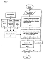
- Fig. 1 is a flowchart of the control means 9.
- the sheet thickness distribution measured by the thickness meter 8 is applied to obtain the measured sheet thickness values corresponding to the respective manipulating points of the thickness adjusting means 10, and in the manipulated variable time series deriving step described later, manipulated variable time series are derived.
- the manipulated variables to be actually delivered to the thickness adjusting means 10 are decided from the derived manipulated variable time series, and are delivered. This process is repeated till the control is completed.
- each control time interval is the time taken for the thickness gauge 8 to measure the thickness distribution of the sheet 1 in the transverse direction of the sheet, or a multiple of the time. Ordinarily, the intervals are tens of seconds to several minutes.
- the control timings are not necessarily required to be fixed cycles, and can be changed as required, depending on the stability condition of the process, etc. For example, in the beginning of production, the control can be carried out at short cycles, and during stable production, the control can be carried out at long cycles.
- the computation in the manipulated variable time series deriving step is to obtain manipulated variable time series from a predetermined manipulated variable time series deriving formula using the measured sheet thickness values and the manipulated variables delivered till then.
- the concept for arriving at this manipulated variable time deriving formula is described below.
- a process model expressing how the sheet thickness changes when manipulated variables are applied to thickness adjusting means 10.
- This process model expresses, as a numerical formula, the lag in the action of the thickness adjusting means after the delivery of the manipulated variables, the delay time taken for the sheet 1 to be carried from the die 4 to the position of the thickness meter 8, and the delay time taken for the thickness meter 8 to measure the thickness profile in the transverse direction, and also the interference that when one thickness adjusting means is manipulated, the sheet changes in thickness at the positions corresponding to the adjacent thickness adjusting means.
- any process model can be used. However, if an individual model is used for each thickness adjusting means, enormous time and labor are needed, and the time series deriving formula becomes too complicated.
- the process model is expressed using a product obtained by multiplying a scalar transfer function expressing the relation between the manipulated variables of thickness adjusting means and the film thickness values at the corresponding positions, by a constant matrix expressing the interferences between individual thickness adjusting means in which at least the diagonal component is not zero.
- a process model can be expressed by the following formula using, for example, a discrete time transfer function.
- y M and u respectively are the sheet thickness values and manipulated variables at the measuring positions corresponding to respective thickness adjusting means, being vectors having elements as many as the number N of thickness adjusting means 10; p and q are the degrees of the discrete time transfer function; and a and b are the respective coefficients; and p, q, a and b are decided considering the delay time and lag in the actual sheet production process.
- W is an N x N matrix expressing the interferences between the individual thickness adjusting means, and expressed by the following formula.
- ⁇ 1 ( ⁇ 0) is the rate at which the sheet thickness values at the positions corresponding to one of the first adjacent thickness measuring means change
- ⁇ 2 ( ⁇ 0) is the rate at which the sheet thickness values at the positions corresponding to one of the second adjacent thickness adjusting means change.
- interference rates are the values expressing how much the sheet thickness changes at the measuring positions corresponding to the adjacent thickness adjusting means in this case. That is, when a certain thickness adjusting means is manipulated, the sheet thickness changes not only at the manipulating position but also in a certain peripheral region due to the rigidity of the die and the influence in the stretching process.
- the rate at which the sheet thickness values at the positions corresponding to both the third and farther adjacent thickness adjusting means change is assumed to be 0, but ⁇ 3 ( ⁇ 0) and more may also be considered. However, it is preferable to assume that ⁇ 3 ( ⁇ 0) and rates at farther thickness adjusting means are 0, since the computation is simpler with little effect on the computation result. Furthermore, as described later, the values of ⁇ 1 and ⁇ 2 of respective rows can also be different from row to row.
- the sheet thickness values y M (t - 1), ..., y M (t - p) and manipulated variables u (t - 1), ..., (t - p) are known at time point t, and g and h can be obtained from the coefficients a and b of the transfer function shown in formula 1 and are known beforehand from the above process model. So, it can be said that the future sheet thickness values y M (t + j) can be calculated if the manipulated variable time series u (t), ..., u (t + j - 1) delivered after the time point t are known.
- the above sheet thickness values are obtained from a process model.
- the process model does not perfectly agree with the actual process, and the actual sheet thickness values become different because of various disturbances, etc. Therefore, even if the sheet thickness values in the far future are obtained to derive the evaluation function for optical control, the manipulated variables are decided using uncertain information with large errors after all unpreferably. So, considered are finite periods of time such as time m (an integer larger than 0) taken to change the manipulated variables and the time P (an integer larger than 0) taken to obtain the sheet thickness values.
- the thickness gauge 8 measures the actual sheet thickness distribution, and from it, the actual sheet thickness values y (t) corresponding to the respective manipulating points of the thickness adjusting means 10 can be known.
- y P y + G F ⁇ U n + G o ⁇ U o + Q o ⁇ y M
- y is a vector as an array of M vectors y (t) respectively having elements as many as N. That is, y P is time series expressing the future sheet thickness changes predicted from the above formula.
- the reference orbit can be set as required according to a conventional method. It can be expressed by, for example, If ⁇ is made closer to 0, an orbit for approaching the designed profile r faster is obtained. It is desirable that the deviation (quadratic form of it) between the sheet thickness prediction formula and this reference orbit is smaller.
- the first term relates to the deviations between the reference orbit and the predictive thickness till the target thickness values are reached
- the second term relates to manipulated variables. ⁇ and ⁇ decide the respective degrees of contribution.
- the measured sheet thickness values y(t) obtained in the previous step are substituted into the y and y R of the above formula, and ⁇ u 0 and ⁇ y M are updated based on the information of till time point t-1, to derive the variations ⁇ u n of the manipulated variable time series, for deciding u(t), ..., u(t + m - 1) from them.
- the manipulated variable time series deriving step and the manipulated variable delivering step are repeated at time points t, t + 1, t + 2, ... That is, at time point t + 1, decided are u(t + 1), ..., u(t + m) using the manipulated variable time series deriving formula, with the newly measured y(t + 1) and the previously delivered u(t) as known values, and among them, u(t + 1) is delivered to the thickness adjusting means 10.
- the manipulated variable time series deriving step can be repeated every time point as described above. Furthermore, it is also possible to derive manipulated variable time series, for example, at time points t, t + s, t + 2s at s cycles, where s is an integer in a range of 2 ⁇ s ⁇ m, and to deliver the u(t), ..., u(t + s -1) derived at time point t in the period from t to t + s - 1.
- the above-mentioned control action computation allows the sheet thickness values to be controlled to have a target thickness profile quickly and high accurately. That is, a process model, which formulates the interference phenomenon that if one thickness adjusting means is manipulated, the sheet thickness values at the portions corresponding to the adjacent adjusting means are changed, and which also formulates the delay time and lag after manipulating one thickness adjusting means till the result appears in the measured thickness value at the corresponding position, is used to decide a thickness prediction formula, and the manipulated variable time series for optimizing the formula are decided and added. So, the sheet thickness values converge on the desired values very quickly and very high accurately.
- a parametric model is described above as the process model.
- the stretching condition in the case where a sheet is stretched in the transverse direction, the stretching condition can be regarded to be almost constant in the transverse direction in the central portion of the sheet, but as shown in Fig.6 edge portions of the produced sheet are likely to be affected by the neck-in phenomenon that the sheet width becomes more narrow immediately after the raw material has been discharged from the die 4 than the width achieved while the raw material is discharged, or by the polymer flow at the die edge portions. So, the sheet is stretched at the edge portions under conditions different from those in the central portion.
- the process model is set differently in the portions corresponding to the edge portions and the central portion in the transverse direction of the sheet as shown in Fig. 1. It is more preferable to set the parameters participating in the decision of the control means, for example, the process gain and interference rate differently for the respective portions.
- a process gain refers to the rate of the controlled variable change to the manipulated variable change. That is, it refers to a value how much the thickness of the sheet changes when a manipulated variable applied to the sheet thickness adjusting means is changed by a unit quantity.
- the borders between the central portion and the edge portions can also be decided in reference to the film forming conditions such as the stretching ratio in the transverse direction of the sheet and the sheet thickness and the distribution of sheet thickness values dispersed in the transverse direction of the sheet. It is also preferable to change the borders depending on the state of film production, for example, to set the width of the central portion at 70 to 80% and the width of the edge portions at the balance in the state of stable film production and to set the width at 60% or less when the sheet thickness in the transverse direction is not stable as in the beginning of film production.
- the process gains it is preferable to keep the process gains in the edge portions smaller than the process gains in the central portion, since it can happen that in the edge portions of the sheet, the sheet thickness does not change so much as in the central portion as shown in the thickness distribution of Fig. 6 due to the structural limit of the die and the buffer effect of the polymer at the die edge portions, even if the manipulated variables for the sheet thickness adjusting means are changed by a certain quantity.
- the die since the die may be fixed at the outermost edge portions or since the several thickness adjusting means in the outermost edge portions may be fixed, it can happen that even if manipulated variables are applied to the sheet thickness adjusting means to keep the sheet thickness thinner in the edge portions, the actually actuated strokes of the thickness adjusting means become small, and furthermore, that since the polymer flow at the die edge portions flow in, the actual sheet thickness in the edge portions does not become as thin as that in the central portion.
- the interference rates at the positions corresponding to the adjacent adjusting means in the edge portions are larger than in the central portion.
- the reasons are the same as those described for the process gains. Since the die may be fixed at the outermost edge portions or since several thickness adjusting means in the outermost edge portions may be fixed, it can happen that when manipulated variables are applied to the sheet thickness adjusting means in the edge portions, the differences from the actually actuated strokes at the positions of the adjacent thickness adjusting means become small, and that since the polymer flow at the die edge portions causes buffer action, the differences between the actual sheet thickness values in the manipulated positions and those in the positions corresponding to the adjacent thickness adjusting means become small.
- the interference rates on the edge portion side can be kept large while those on the central portion side are kept small.
- both the process gain and interference rate can be set respectively differently for the right and left edge sides in the sheet running direction.
- the process gains and interference rates in the central portion and the edge portions used for expressing the process model it is preferable to measure the step responses of the thickness adjusting means. That is, if step-wise changing manipulated variables are applied to thickness adjusting means representing the edge portions and thickness adjusting means representing the central portion, the process gains and interference rates in the edge portions and the central portion can be measured from the changes in sheet thickness caused in this case.
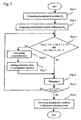
- the control parameter is decided according to the method shown in Fig. 5.
- the control parameter to be decided depends on the design method.
- a process model is prepared based on the process gains, interference rates and delay time decided according to the methods of the invention. Since the process gains in the edge portions of the film are smaller than those in the central portion, the control parameter is adjusted to keep the control gains in the edge portions larger than those in the central portion, and the process model is used to simulate the changes of sheet thickness. If the control performance such as the control accuracy and the responsiveness obtained by the simulation is better than the preset standard values, the design parameter concerned is employed. If the control performance is not good, the control parameter is re-adjusted to carry out the simulation. This work is repeated to decide the optimum control parameter.
- a process model prepared according to the invention is used to simulate the changes of sheet thickness for deciding the control parameter of the control means as described above, a sheet can be produced efficiently since it can be avoided to decide the control parameter by trial and error while forming the sheet.
- the sheet thickness can be controlled accurately and stably even at the edge portions of the sheet that are likely to be affected by the neck-in phenomenon and the polymer flow at the die edge portions, hence likely to be unstably controlled.
- the manipulated variable applied to each thickness adjusting means 10 also affects the positions of the near thickness adjusting means. So, in a state where the differences between the manipulated variables of the respective near thickness adjusting means are excessively large, even if the differences between the manipulated variables of the respective near thickness adjusting means are made larger, the form of the gap cannot follow the differences of manipulated variables. For this reason, the manipulated variables can less affect the changes of gap form of the die, and since the gap adjusting capability becomes low, the sheet thickness control accuracy declines.
- the number of thickness adjusting numbers is N (N: a natural number of 2 or more)
- N a natural number of 2 or more
- the manipulated variable delivered to said i-th thickness adjusting means is corrected to keep the differences of manipulated variables smaller, while the manipulated variables delivered to said near thickness adjusting means are corrected based on a static process model expressing the static relation between manipulated variables to be delivered and the sheet thickness values at the position corresponding to the respective thickness adjusting means, to be obtained by the manipulated variables after lapse of a sufficient time, and that the corrected respective manipulated variables are delivered to said respective thickness adjusting means.
- the control means 9 has a manipulated variable computing means 221, manipulated variable correcting means 222 and manipulated variable delivering means 223 as shown in Fig. 8.
- the manipulated variable computing means 221 computes manipulated variables according to a predetermined control algorithm, and the manipulated variable correcting means 222 corrects manipulated variables when it is necessary to correct them.
- the manipulated variable delivering means 223 delivers the respective corrected values actually to the thickness adjusting means 10.
- the manipulated variable computing means 221 it is preferable to perform conversion processing such as filter processing for the deviation data that are differential values between the thickness distribution of the sheet 1 and the desired thickness distribution.
- filter processing such a method as the moving-averaging in the same direction as the transverse direction of the sheet or the weighted-averaging with the deviation data obtained before the present time point can be used.
- the number of the thickness adjusting means 10 arranged in the transverse direction of the sheet is smaller than the number of said deviation data.
- the data corresponding to the respective thickness adjusting means are taken from the filter-processed deviation data. In this case, it is desirable to obtain beforehand the corresponding positions between the respective thickness adjusting means 10 and the deviation data.
- the manipulated variable computing means 221 computes the manipulated variables for the filter-processed deviation data reduced to as many as the thickness adjusting means, for controlling the thickness adjusting means 10.
- Fig. 7 shows an example of manipulated variables 28 delivered to respective thickness adjusting means 10.
- the position of each thickness adjusting means is selected as the abscissa, and the magnitude of the manipulated variable, as the ordinate.
- the magnitude of the manipulated variable can be, for example, the rate of time during which a certain heat quantity is delivered to the thickness adjusting means concerned or the magnitude of the heat quantity delivered to the thickness adjusting means concerned during a predetermined period of time.
- the manipulated variable of the thickness adjusting means of position x or y is excessively larger or smaller than the manipulated variables a delivered to the thickness adjusting means of the near positions x - 1 and x + 1, or y - 1 and y + 1.
- the static mathematical relation between u i and y i is; for example, as shown in formulae 19 and 20.
- the static mathematical relation refers to the relation between sheet thickness values and manipulated variables occurring after lapse of a sufficient time subsequently to the application of the manipulated variables to the thickness adjusting means.
- A is an interference matrix, being a matrix with a size of N x N expressing the interferences between individual thickness adjusting means.
- ⁇ 1 ( ⁇ 0) is the rate at which the sheet thickness values at the positions corresponding to both the first adjacent thickness measuring means change
- ⁇ 2 ( ⁇ 0) is the rate at which the sheet thickness values at the positions corresponding to both the second adjacent thickness adjusting means change.
- the rate at which the sheet thickness values at the positions corresponding to both the third and farther adjacent thickness adjusting means change is assumed to be 0, but ⁇ 3 ( ⁇ 0) and rates of farther thickness adjusting means may also be considered.
- the values of ⁇ 1 and ⁇ 2 of respective rows can also be different from row to row.
- A" + is a quasi-inverse matrix of A
- A" is a matrix obtained by extracting the portion of (j + M2, j + M2) from the elements (j - M1, j - M1) of matrix A and excluding the j-th column of A.
- the correction rates of the manipulated variables can be derived and the manipulated variables can be leveled with the sheet thickness little changed.
- the correction rate a of the manipulated variable applied to the j-th thickness adjusting means is not larger than 10% of the manipulated variable applied to the j-th thickness adjusting means. In the case where 10% or more of correction is needed, it is preferable to carry out the leveling plural times by several percent each. In this case, it is desirable that the leveling subsequent to the completion of one time of leveling is carried out after the sheet thickness becomes stable.
- the correction rates can be added to the manipulated variables.
- the correction rates can be obtained after the manipulated variables have been applied to the thickness adjusting means before the next manipulated variables are delivered, and added to the manipulated variables obtained in the next control computation, to deliver the corrected manipulated variables to the thickness adjusting means.
- step 3 the respective absolute values of D k and D k+1 are compared with a predetermined threshold value, and the signs of D k and D k+1 are examined.
- steps 3 through 5 are carried out.
- step 7 The above steps are repeated till k ⁇ N is reached (step 7), and the corrected manipulated variables are actually delivered to the thickness adjusting means (step 8).
- Other methods of deciding the positions of the thickness adjusting means, the correction rates of which are obtained based on D k include a method of deciding for a predetermined number of adjusting means selected in the descending order of absolute value of D k and a method of deciding based on the absolute value of the product of adjacent differences D k or the sum of the absolute values of adjacent differences D k , etc.
- the correction rate a can be set at a constant rate to the manipulated variable to be corrected, or can also be derived in response to the difference between the manipulated variables of adjacent thickness adjusting means, i.e., based on the magnitude of D i .
- b i can also be given beforehand like a, to derive other correction rates.
- leveling is carried out every control cycle, but can also be carried out intermittently.
- the number of thickness adjusting means is N (N: a natural number of 2 or more)
- N a natural number of 2 or more
- M a natural number of 2 to N
- a process model that expresses the relation between the manipulated variables to be delivered and the sheet thickness values to be obtained by the manipulated variables, in order to minimize the dispersion of the manipulated variables to be delivered to said consecutive M thickness adjusting means among the manipulated variables of the N thickness adjusting means.
- A' is an interference matrix, being a matrix with a size of M x M expressing the interferences between individual thickness adjusting means.
- ⁇ 1 ( ⁇ 0) is the rate at which the sheet thickness values at the positions corresponding to both the first adjacent thickness measuring means change when a manipulated variable is changed at a certain thickness adjusting means
- ⁇ 2 ( ⁇ 0) is the rate at which the sheet thickness values at the positions corresponding to both the second adjacent thickness adjusting means change.
- the rate at which the sheet thickness values at the positions corresponding to both the third and farther adjacent thickness adjusting means change is assumed to be 0, but ⁇ 3 ( ⁇ 0) and the rates of farther thickness adjusting means may also be considered.
- the values of ⁇ 1 and ⁇ 2 of respective rows can also be different from row to row.
- the manipulated variables (u' 1 , u' 2 , ..., u' M ) T not yet corrected and to be delivered to the respective thickness adjusting means 10 j are considered as vector U'.
- U can be expressed as follows, as the linear combination of eigenvectors v i .
- a i is coefficients expressing the degrees at which eigenvectors v i are contained in U', and is obtained from the following formula (step 2).
- the change of thickness y' i by the change of manipulated variables u can be expressed as follows using v i , ⁇ i and a i .
- the manipulated variables can be leveled with the sheet thickness little changed. If the threshold value T 1 is made larger, the degree of leveling can be enhanced since many kinds of frequency components can be removed from the manipulated variable vector U', but the influence on the sheet thickness tends to be larger. On the other hand, if the threshold value T 1 is made smaller, the influence on the sheet thickness can be lessened, but the degree of leveling tends to be lower. It is preferable that the threshold value T 1 is 0.01 to 0.5.
- the manipulated variables can also be corrected using said formula 33, assuming that the a i corresponding to the eigenvalue ⁇ i satisfying the following formula is 0.
- Formula 34 ⁇ i ⁇ max j ( ⁇ j ) ⁇ T 2 where 0 ⁇ T 2 ⁇ 1, preferably 0.01 ⁇ T 2 ⁇ 0.5.
- the leveling can be carried out every control cycle, but can also be carried out intermittently. Furthermore, carrying out the leveling in the case where a certain condition is satisfied is also a preferable mode. For example, it is preferable to carry out leveling in the case where the variance of the manipulated variables delivered to consecutive M thickness adjusting means has become larger than a preset value, or in the case where the difference between the maximum value and the minimum value of the manipulated variables delivered to M thickness adjusting means becomes larger than a preset value, or in the case where the difference between the manipulated variables delivered to adjacent thickness adjusting means becomes larger than a preset value.
- the number M of the thickness adjusting means to be leveled is 2 to N.
- M N, i.e., where M is equal to the number of all the thickness adjusting means (N), is preferable since the manipulated variables of all the thickness adjusting means can be leveled as a package. M can also be set at any desired values smaller than N. In this case, since computation covers only the portions that must be leveled, computation can be simplified.
- the thickness adjusting means 10 can be any of heat bolt method, lip heater method, etc.
- heat bolt method heat quantities are given to heat bolts, to change their temperatures, thereby thermally expanding or contracting them, for adjusting the gap 11 of the die 4.
- lip heaters are used to change the temperatures of the polymer, to change the viscosities of the polymer so that the amounts of the polymer extruded from the die 4 can be changed to adjust the thickness values of the sheet 1.
- the temperature is adjusted to adjust the sheet thickness.
- each thickness adjusting means 10 if the temperature of each thickness adjusting means 10 is raised, the sheet thickness becomes thinner since the gap of the die is narrowed. On the contrary, in the lip heater method, if the temperature is raised, the sheet thickness becomes thicker since the viscosity of the polymer declines to increase the amount extruded from the die.
- the thickness adjusting means 10 are forcibly heated, for example, by applying electric powers as described above, but when the temperatures are lowered, the thickness adjusting means 10 are naturally allowed to cool in most cases.
- the change of the sheet thickness with the lapse of time when the temperature is raised is different from that when the temperature is lowered. Compared with the case of raising the temperature, the change of the sheet thickness with the lapse of time occurs slowly when the temperature is lowered.
- heating type thickness adjusting means are used and where the manipulated variables are controlled by controlling the heat quantities applied to the heating type thickness adjusting means, it is preferable that the variations of the heat quantities are made larger when the heat quantities are decreased than when they are increased.
- the manipulated variable computing means 21 computes the heat quantities 23 based on the differential values 25 between the measured thickness values 24 and the desired thickness values of the sheet 1, and the computed heat quantities are applied to the thickness adjusting means 10 of the sheet production process 26.
- the heat quantities are given as electric currents applied to the heating type thickness adjusting means.
- the control means 9 computes the heat quantities based on the filter-processed deviation data reduced to as many as the number of the thickness adjusting means, to control the thickness adjusting means 10.
- the sheet thickness values become smaller since the gap of the die become smaller.
- the sheet thickness values become larger since the viscosities of the polymer are lowered to increase the amounts extruded from the die.
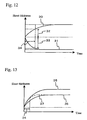
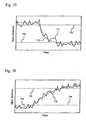
- Fig. 12 is a schematic diagram showing the change 31 of sheet thickness with the lapse of time in the case of heating a heat bolt and the change 30 of sheet thickness with the lapse of time in the case of cooling the heat bolt, with the same heat quantity variation given in reverse directions. It can be seen that the change of sheet thickness in the case of cooling the heat bolt is slow compared with that in the case of heating the heat bolt.
- Fig. 13 shows a schematic diagram showing the changes of sheet thickness with the lapse of time with the heat bolt cooled with a large heat quantity and a small heat quantity.
- Fig. 13 also shows the sheet thickness change 37 with the lapse of time in the case where the heat quantity is small and where the time constant of the process is small i.e. the sheet thickness changes quickly.
- the sheet thickness variation is the same as that in the case where the heat quantity is large.
- the certain time 34 is a control cycle, it can be considered that the same sheet thickness change as that in the case where the time constant is small occurs in this control cycle if the heat quantity is made larger. That is, as shown in Fig. 11 (a), if the basic heat quantity computing means 211 computes the variation of heat quantity (basic heat quantity) to be given on the assumption that the responsiveness during cooling is the same as that during heating in defiance of actually asymmetric responsiveness, and the heat quantity for control is obtained to ensure that the variation becomes ⁇ times( ⁇ > 1), then the responsiveness in the case of cooling the heat bolt can be improved.
- the basic heat quantity computing means 211 computes the variation of heat quantity (basic heat quantity) to be given on the assumption that the responsiveness during cooling is the same as that during heating in defiance of actually asymmetric responsiveness, and the heat quantity for control is obtained to ensure that the variation becomes ⁇ times( ⁇ > 1), then the responsiveness in the case of cooling the heat bolt can be improved.
- the heat quantity in the case of cooling a heat bolt is made larger in reference to the case of heating the heat bolt, but on the contrary, the heat quantity in the case of heating the heat bolt can be made smaller in reference to the case of cooling the heat bolt (first mode).
- control differential value between said measured value and said desired value used for cooling can be multiplied by ⁇ (0 ⁇ ⁇ ⁇ 1), to obtain the heat quantity and it can be applied to the heating type thickness adjusting means (third mode).
- ⁇ , ⁇ and ⁇ are decided considering the process gains, time constant of heating/cooling and control cycles. Furthermore, ⁇ , ⁇ and ⁇ can also be variable depending on the magnitudes of the differences between desired thickness values and measured thickness values, instead of being constant values.
- control system can be constituted to allow the computation of such asymmetric control output.
- the sheet In the equipment of producing a sheet such as a film, the sheet is wound around a winder, and slight roughness of the sheet in the transverse direction can cause a winding mound as shown in Fig. 15.
- an oscillator is installed upstream of the winder, to oscillate the sheet in the transverse direction, i.e., crosswise while the sheet is wound. If the sheet is oscillated crosswise to move thick portions crosswise in the transverse direction like this, the occurrence of a winding mound can be prevented.
- an integrating circuit 41 integrates the deviations 44 between the measured thickness values 24 of the sheet formed according to the sheet production process measured by the thickness gauge 8 at the respective measuring positions after a given measuring start point, and the first target values 42 at the positions corresponding to the measured thickness values.
- the outer diameter profile can be, for example, flat or drum-shaped in the transverse direction, and any profile desired by the user can be set.
- a second target value correcting means 40 corrects the second target values at the positions corresponding to the integral values based on the integral values.
- the second target values for example, the desired thickness values of one sheet can be set.
- the second target values can be corrected at rates proportional to the magnitudes of the integral values, or PID control or the like can be used. In this case, it is desirable that an upper limit value and a lower limit value are preset for the second target values, to prevent that the second target values are corrected beyond the upper or lower limit value.
- the manipulated variable computing means 21 derives the manipulated variables for the thickness adjusting means 10 in order to lessen deviations between said corrected second desired values 43 and the measured thickness values 24 using said evaluation function.
- filter processing such a method as the moving-averaging in the same direction as the transverse direction of the sheet or the weighted-averaging with the deviation data obtained before the present time point can be used. It is desirable to decide the manipulated variables depending on the situations in the production process, for example, to correct large thickness irregularity immediately after start of sheet production and to correct small thickness irregularity during stable production.
- the number of the thickness adjusting means 10 disposed in the transverse direction of the sheet is smaller than the number of measured deviation data.
- the data corresponding to the respective thickness adjusting means are taken from the filter-processed deviation data.
- the data can be obtained using a function of thickness distribution and the fitting of the least square method, etc.
- the corresponding data can also be obtained by simply thinning out. In this case, it is desirable to obtain the corresponding relation between the respective thickness adjusting means 10 and the measured thickness values 24 beforehand.
- the manipulated variable computing means 21 computes the manipulated variables 23 based on the filter-processed deviation data reduced to as many as the number of the thickness adjusting means, and the manipulated variable delivering means 22 delivers the manipulated variables 23 to the thickness adjusting means 10 of the sheet production equipment 26.
- the manipulated variable computing means 21 takes the values of the positions corresponding to the respective thickness adjusting means 10 and computes the manipulated variables based on these values.
- the first desired values 42, the second desired values 43, the measured thickness values 24 and the deviation data 44 and 25 can also be reduced to only the data of the positions corresponding to the respective thickness adjusting means 10 beforehand.
- the correction of the second desired values is not necessarily carried out frequently, when the integrating means 4 integrates the differences from the first desired values, it is not necessary to use the latest values at that moment. Therefore, the values measured at an adequately less frequency can be used, or the values measured by any other means than that for the measured values used in the manipulated variable computing means 21 can also be used.
- the correction of second desired values can also be carried out at longer cycles.
- the outer diameter profile of the produced roll can be improved.
- the outer diameter profile can be measured using a stylus method or laser displacement meter, etc. Since the winding diameter is small when little time has passed after start of winding, the velocity of increasing the winding diameter is wound more than when a certain time has passed after start of winding. So, when the winding . diameter is small, the thickness irregularity affects the profile of the produced roll greatly. Therefore, if the correction rates of the second desired values are made smaller as the winding diameter of the sheet becomes larger, the sheet can be produced without being affected by the winding diameter.
- the thickness irregularity of the sheet is the thickness irregularity of the sheet.
- the conventional thickness irregularity decreasing technique as described above has various problems. The inventors studied intensively and as a result found that if a specific component of sheet thickness irregularity is selectively decreased, a slightly wrinkled or streaked roll with a good roll form can be obtained without changing the properties of the sheet with high productivity sustained.
- the thickness profile in the transverse direction of the sheet is measured and Fourier-transformed into a power spectrum resolved into wave numbers, and the sheet thickness is controlled to ensure that the mean value X1 of the powers of smaller than a predetermined wave number a becomes 0.2 x T 2 or less and not larger than the mean value X2 of the powers of wave number a and more in said power spectrum.
- the influence of the component of smaller than a specific wave length on the winding appearance is large, and if the mean value X1 of the powers of smaller than said wave number a is 0.2 x T 2 or less, the irregularity of the winding appearance of the roll formed by winding the sheet can be kept very small.
- T is the mean thickness ( ⁇ m) of the sheet. It is preferable that X1 is 0.1 x T 2 or less. Furthermore, if the mean value X2 of the powers of said wave number a and larger is larger than the mean value X1 of said powers, high productivity can be sustained without changing the properties of the sheet. A range of X1 ⁇ 0.5 x X2 is preferable, and a range of X1 ⁇ 0.2 x X2 is more preferable.
- the predetermined wave number a can be set depending on the kind of the sheet and production conditions, and it is preferable that the wave number is any optional value selected in a range from 3 m -1 to 30 m -1 .
- the low frequency component of smaller than this wave number worsens the winding appearance of the roll since the thickness irregularity is accumulated.
- the high frequency component of larger than this wave number does not affect the winding appearance of the roll so much.
- the method of measuring the thickness profile of a plastic film (hereinafter simply called the film) in the transverse direction is as described below.
- the film a plastic film
- several sheets to tens of sheets are cut out from optional winding layers of a produced roll, and the thicknesses of discretely sampled portions can be measured, for example, using a contact measuring instrument. It is preferable that the sampling intervals are 1 mm or less.
- the measurement can also be carried out at different positions in the longitudinal direction of the film, to average the power spectra obtained in the respective times of measurement.
- the obtained thickness profile of the sheet in the transverse direction are Fourier-transformed according to the following formula, to obtain the power spectrum P of the respective wave numbers.
- P F ( ⁇ ) F ( ⁇ )*
- f(x) is the thickness profile of the sheet in the transverse direction (in ⁇ m);
- F( ⁇ ) is the Fourier transform of f(x);
- x is a position in the transverse direction of the sheet (in ⁇ m);
- ⁇ (in m -1 ) is a wave number;
- F( ⁇ )* is a conjugate complex number;
- the mean value X1 of the powers of a predetermined wave number a and larger and the mean value X2 of the powers of smaller than the wave number a are obtained as described below. That is, X1 is the mean value of the powers whose wave number is more than 0 and smaller than the wave number a, and shows the degree to which the thickness irregularity of the low frequency component is contained in the film. X2 is the mean value of the powers of the predetermined wave number a and larger, and shows the degree to which the thickness irregularity of the high frequency component is contained in the film.
- the upper limit of the wave number computed when X2 is obtained can be the upper limit of the obtained power spectrum. However, if too high wave numbers are included in the computation, noise may be contained.
- X2 is the mean value of the powers of the predetermined wave number a to 100 m -1 , and it is more preferable that X2 is the mean value of the powers of the predetermined wave number a to 40 m -1 .
- the predetermined number a is equal to 1/(an interval between respectively adjacent thickness adjusting means x the stretching ratio of the sheet in the transverse direction).
- the thickness irregularity of wave numbers of larger than it little affects the winding appearance of the roll and the control by the thickness adjusting means becomes difficult.
- the oscillation means to reciprocate the roll as a wound film in the transverse direction of the roll when the film is wound. If the film is oscillated especially in an amplitude range of 0.5 x (1/wave number a) ⁇ (Oscillation amplitude) ⁇ 5 x (1/wave number a), when wound, the thickness irregularity of high wave numbers little affects the winding appearance.
- the sheet thickness can be controlled to have a desired thickness profile quickly at high accuracy.
- the low frequency component in the thickness irregularity of the sheet can be efficiently removed.
- control means in the above embodiments can be realized by means of a computer, a program for causing those actions, etc.
- the program and the data of various storing means can be distributed by tangible media available for computer reading such as floppy disc, MO and CD-ROM and transmission means such as wired or wireless network.
- the sheet production equipment shown in Fig. 2 was used to produce a 2.7 ⁇ m thick polyester film.
- the width of the produced film was 3.5 m, and the film forming speed in the product portion was 175 m/min.
- Each of the thickness adjusting means 10 was a heat bolt containing a cartridge heater for thermally expanding and contracting the bolt, thereby adjusting the gap 11.
- the number of heat bolts used for thickness control was 45.
- the thickness gauge 8 used was a light interference type thickness gauge using the interference phenomenon of light described in JP, 4-522, B. The thickness gauge can measure the film thickness at 15 mm intervals in the transverse direction of the film while scanning at cycles of 60 seconds in the transverse direction of the film. The control interval were 60 seconds equal to the scanning cycles of the thickness gauge.
- the process model of formula 1 was decided as shown by the following formula, based on the sheet thickness changes near the measuring position corresponding to one heat bolt to which a predetermined manipulated variable was applied.
- a manipulated variable refers to the rate of time during which a heat quantity is applied to each heat bolt.
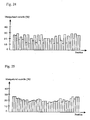
- manipulated variables were applied to plural heat bolts to intentionally make thickness irregularity (obtained by dividing the difference between the maximum value and the minimum value of thickness by a mean thickness value), and the thickness of the film was controlled according to the method of the invention.
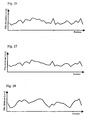
- Fig. 16 shows the control result of PID control
- Fig. 17, the control result of the method of the invention.
- the thickness irregularity was improved from 8.4% to only 7.4%, but in Fig. 17, similarly in control of about 30 minutes, the thickness irregularity was improved from 9.1% to 1.4%. It could be confirmed that when the method of the invention was used, the sheet thickness could be controlled to have a desired profile quickly at good accuracy.
- the range of respectively 35% on both sides of a center in the transverse direction of a film was defined as the central portion, and the remaining ranges of 15% each on both sides, as the edge portions.
- Predetermined manipulated variables were applied to respectively optional heat bolts in the central portion and the edge portions.
- Thickness irregularity of a similar degree to those of Examples 1 and 2 was made in the entire width of the sheet, and the method of the invention was applied to control the film thickness. As a result, the thickness became more uniform over the entire width of the film than in Examples 1 and 2, and the film could be formed stably.
- the sheet production equipment shown in Fig. 2 described above was used to produce a 2.7 ⁇ m thick polyester film.
- Each of the thickness adjusting means 10 was a heat bolt containing a cartridge heater for thermally expanding and contracting the bolt, thereby adjusting the gap 11.
- the number of heat bolts used for thickness control was 45, and the respective bolts were arranged at a pitch of 20 mm.
- the thickness gauge 8 used was a light interference type thickness gauge using the interference phenomenon of light.
- the width of the produced film was 3.5 m, and the film forming speed in the product portion was 175 m/min.
- a process gain refers to the rate of the sheet thickness changes to the manipulated variable changes applied to a heat bolt.
- the manipulated variable of a heat bolt is the percentage of the time during which a certain electric power is supplied to the heat bolt, to a certain period time (10 seconds). Therefore, the unit of a process gain is ⁇ m/%.
- An interference rate expresses the change of the sheet thickness at the positions correspond to a certain operated heat bolt, and a first adjacent position or second adjacent position of the bolt caused when said heat bolt is operated, with the change at the position correspond to the operated heat bolt as 1.
- time constant T and dead time Td existed as dynamic characteristics of the process model.
- the time constant T and the delay time Td were identified from the step response test. In this example, as shown in Table 1, equal values were obtained for the edge portions and the central portion.
- Fig. 18 shows the control result of sheet thickness obtained when the thickness of the plastic film produced using the controller decided based on the process model described above was stabilized after lapse of sufficient time.
- the control range was from No. 11 bolt to No. 52 bolt (corresponding to the positions of 600 mm and 310 mm from the edges of the produced film), and the central portion ranged from No. 18 bolt to No. 45 bolt. As shown in the diagram, the thickness became uniform over the entire width, and the film could be formed stably.
- the production equipment shown in Figs. 2 and 3 with a die 4 having 40 heat bolts used as the thickness adjusting means 10 was used to produce a plastic film.
- a manipulated variable in this example refers to the rate of time during which a heat quantity is applied to a heat bolt, per predetermined period of time.
- the leveling was carried out automatically as shown in Fig. 9.
- the threshold value T in step 3 of Fig. 9 was set at 15%, and the correction rate a was set at -5%.
- the thickness adjusting means corrected at a time were one thickness adjusting means greatly different in the manipulated variable from both the adjacent thickness adjusting means, and the respectively two adjacent thickness adjusting means on both sides of it, five thickness adjusting means in total.
- the pattern of manipulated variables at a certain time point during the sheet thickness control was as shown in Fig. 20, and the pattern of the differential values between the manipulated variables delivered to adjacent thickness adjusting means was as shown in Fig. 21.
- the magnitude of the manipulated variable is chosen as the ordinate of this graph, and it expresses the rate of the time during which a certain heat quantity is delivered to a heat bolt, per predetermined period of time.
- the value of the manipulated variable at position i + 1 projects by about 20% compared with the values of both the adjacent positions.
- the calculated correction rates were added to the manipulated variables, and the sums were delivered to the thickness adjusting means.
- Fig. 22 shows the change with the lapse of time, of the measured thickness value corresponding to the thickness adjusting means at position i + 1 that received the manipulated variable 60.
- the sheet thickness little changed with the lapse of time.
- the manipulated variables were corrected to reduce the differences between the manipulated variable 60 and the manipulated variables of both the adjacent positions to 10% or less in the pattern of manipulated variables as shown in Fig. 20 using the method described in JP, 7-329147, A Gazette.
- the change of the sheet thickness with the lapse of time in this case is shown in Fig. 23.
- the production equipment shown in Figs. 2 and 3 with a die 4 having 38 heat bolts used as the thickness adjusting means 10 was used to produce a plastic film.
- a manipulated variable in this example refers to the rate of the time during which a heat quantity was applied to a heat bolt, per predetermined period of time.
- the pattern of manipulated variables at a certain time point during the sheet thickness control became as shown in Fig. 24.
- the magnitude of the manipulated variable is chosen as the ordinate of this graph, and it expresses the rate of the time during which a certain heat quantity was delivered to a heat bolt, per predetermined period of time. Since the standard deviation of the manipulated variables at this moment was 3.5%, the manipulated variables were leveled.
- Fig. 25 shows the leveled manipulated variable pattern applied to the thickness adjusting means. As a result, the standard deviation of manipulated variables became 2.3%. So, the leveling could make the standard deviation of manipulated variables smaller.
- Fig. 26 shows the sheet thickness distribution before leveling
- manipulated variables were corrected sequentially in the descending order of the magnitude of the difference between the manipulated variables of respectively adjacent thickness adjusting means, in order to become the difference between the manipulated variables at both the adjacent positions 7% or less in the pattern of manipulated variables as shown in Fig. 24 using the method described in JP07329147A.
- the sheet thickness distribution obtained when the standard deviation of manipulated variables became 2.3% is shown in Fig. 28.
- Figs. 29 and 30 The mean values 71 and 73 in the change of film thickness with the lapse of time in this case are shown in Figs. 29 and 30.
- broken lines 72 and 74 are obtained by functionally approximating 71 and 73. Comparing the time taken for the approximation curve 72 to change from 10% of the entire variation to 90% (dotted lines 75 and 76 in Fig. 29) with that for the approximation curve 76 to change similarly (dotted lines 75 and 76 in Fig. 30), the time in the case of heating (pushing) (72) is shorter than that in the case of cooling (pulling) (74) by a factor of about 1.4.
- Fig. 31 shows the outer diameter profile 81 of the roll produced in this case. Since the pulling action was slow and insufficient, the outer diameter profile was generally thinner than the desired value.
- Fig. 31 shows the outer diameter profile 82 of the roll produced in this case.
- the corresponding heat bolts are cooled.
- the irregularity of the outer diameter profile of the roll generally decrease as in this example.
- the sheet production equipment shown in Fig. 2 as described above was used to produce a 2.7 ⁇ m thick polyester film.
- the thickness adjusting means 10 heat bolts each containing a cartridge heater for thermally expanded and contracted to adjust the gap 11 were used.
- the number of the heat bolts used for thickness control was 45, and the bolts were arranged at a pitch of 20 mm.
- the sheet width of the product portion was 3.5 m, and the stretching ratio in the transverse direction of the sheet was 3.5 times.
- a step of measuring the thickness distribution of the sheet in the transverse direction a step of deriving manipulated variable time series in which a predetermined evaluation function for evaluating the future sheet thickness changes predicted based on said measured values and on a process model expressing the relation between said manipulated variables and sheet thickness values becomes a minimum value, and a step of delivering at least the first manipulated variables of said manipulated variable time series to said thickness adjusting means were repeated at predetermined intervals.
- the wound roll was divided into three rolls, and from the respective surface layers of the rolls, 10 sheets each were cut out, and the thickness of the sheets were measured by a contact film thickness gauge at 0.5 mm intervals.
- the power spectrum 90 was as shown in Fig. 32.
- heat bolts were used as the thickness adjusting means, but the thickness adjusting means are not especially limited if they suit the objects of the invention.
- actuators such as servomotors or pneumatic motors and die bolts can also be used.
- the elements for changing the manipulated variables of thickness adjusting means can be other than energizing times and voltages, such as the rotating angles of die bolts and heater temperatures.
- the method of manufacturing sheet of the invention can control the sheet thickness to have a desired thickness profile at high speed, the time taken after starting the production of the sheet till a predetermined thickness irregularity level acceptable as a product is reached can be shortened to remarkably reduce the quantity of non-conforming products produced in this duration and to enhance the production efficiency, thus allowing the sheet cost to be reduced. Furthermore, even if the thickness profile of the sheet changes, for example, since the temperature distribution of the stretching machine changes during film formation, it can be controlled to have a desired profile quickly. So, as a result, the thickness uniformity of the sheet can be improved to improve the quality of the sheet.
Priority Applications (1)
| Application Number | Priority Date | Filing Date | Title |
|---|---|---|---|
| EP08014707A EP1987942A3 (de) | 2000-09-21 | 2001-09-17 | Durch Extrudieren und Formen eines Rohstoffes erzeugtes Blatt |
Applications Claiming Priority (3)
| Application Number | Priority Date | Filing Date | Title |
|---|---|---|---|
| JP2000286881 | 2000-09-21 | ||
| JP2000286881 | 2000-09-21 | ||
| PCT/JP2001/008043 WO2002024434A1 (fr) | 2000-09-21 | 2001-09-17 | Procede de fabrication d'une feuille, dispositif et programme permettant de reguler l'epaisseur d'une feuille et feuille ainsi obtenue |
Related Child Applications (1)
| Application Number | Title | Priority Date | Filing Date |
|---|---|---|---|
| EP08014707A Division EP1987942A3 (de) | 2000-09-21 | 2001-09-17 | Durch Extrudieren und Formen eines Rohstoffes erzeugtes Blatt |
Publications (3)
| Publication Number | Publication Date |
|---|---|
| EP1319492A1 true EP1319492A1 (de) | 2003-06-18 |
| EP1319492A4 EP1319492A4 (de) | 2008-01-23 |
| EP1319492B1 EP1319492B1 (de) | 2009-04-15 |
Family
ID=18770736
Family Applications (2)
| Application Number | Title | Priority Date | Filing Date |
|---|---|---|---|
| EP01967698A Expired - Lifetime EP1319492B1 (de) | 2000-09-21 | 2001-09-17 | Verfahren zur bahnherstellung ,vorrichtung und programm zur regelung der bahndicke, und bahn |
| EP08014707A Withdrawn EP1987942A3 (de) | 2000-09-21 | 2001-09-17 | Durch Extrudieren und Formen eines Rohstoffes erzeugtes Blatt |
Family Applications After (1)
| Application Number | Title | Priority Date | Filing Date |
|---|---|---|---|
| EP08014707A Withdrawn EP1987942A3 (de) | 2000-09-21 | 2001-09-17 | Durch Extrudieren und Formen eines Rohstoffes erzeugtes Blatt |
Country Status (8)
| Country | Link |
|---|---|
| US (1) | US6856855B2 (de) |
| EP (2) | EP1319492B1 (de) |
| KR (2) | KR100846756B1 (de) |
| CN (2) | CN100478157C (de) |
| DE (1) | DE60138399D1 (de) |
| MY (1) | MY132032A (de) |
| TW (1) | TW523456B (de) |
| WO (1) | WO2002024434A1 (de) |
Cited By (6)
| Publication number | Priority date | Publication date | Assignee | Title |
|---|---|---|---|---|
| DE10300375A1 (de) * | 2003-01-06 | 2004-07-15 | Windmöller & Hölscher Kg | Verfahren zur Regelung der Dicke extrudierter Folie I |
| WO2004060634A1 (de) | 2003-01-06 | 2004-07-22 | Windmöller & Hölscher Kg | Verfahren zur regelung der dicke extrudierter folie |
| EP2014813A1 (de) | 2007-07-09 | 2009-01-14 | Oskar Dilo Maschinenfabrik KG | Verfahren zum Herstellen einer verfestigten Vliesstoffbahn |
| US9579684B2 (en) | 2011-06-07 | 2017-02-28 | 3M Innovative Properties Company | Slot die position adjustment control |
| EP4082764A1 (de) * | 2021-04-27 | 2022-11-02 | Rheinspan GmbH & Co. KG | Verfahren und vorrichtung zur prüfung eines spänekuchens |
| WO2023213975A1 (en) * | 2022-05-04 | 2023-11-09 | Bühler AG | Industrial extruder, process and method thereof |
Families Citing this family (31)
| Publication number | Priority date | Publication date | Assignee | Title |
|---|---|---|---|---|
| DE10233136B4 (de) * | 2002-07-20 | 2005-12-01 | Battenfeld Extrusionstechnik Gmbh | Steuerung für eine Kompaktanlage |
| DE10314573A1 (de) | 2003-03-31 | 2004-10-28 | Henkel Kgaa | Verfahren zum rechnergestützten Regeln einer Mehrzahl von in Serie miteinander gekoppelten Maschinen, Regelungseinrichtung und Maschinen-Anordnung |
| US7117046B2 (en) * | 2004-08-27 | 2006-10-03 | Alstom Technology Ltd. | Cascaded control of an average value of a process parameter to a desired value |
| US7634417B2 (en) * | 2004-08-27 | 2009-12-15 | Alstom Technology Ltd. | Cost based control of air pollution control |
| US7536232B2 (en) * | 2004-08-27 | 2009-05-19 | Alstom Technology Ltd | Model predictive control of air pollution control processes |
| US7522963B2 (en) * | 2004-08-27 | 2009-04-21 | Alstom Technology Ltd | Optimized air pollution control |
| US7113835B2 (en) * | 2004-08-27 | 2006-09-26 | Alstom Technology Ltd. | Control of rolling or moving average values of air pollution control emissions to a desired value |
| US7323036B2 (en) * | 2004-08-27 | 2008-01-29 | Alstom Technology Ltd | Maximizing regulatory credits in controlling air pollution |
| KR100612775B1 (ko) * | 2004-12-01 | 2006-08-21 | 한국타이어 주식회사 | 압출 고무시트의 두께를 연속적으로 제어하기 위한 방법 |
| CN101365571B (zh) * | 2005-11-30 | 2011-05-04 | 东丽株式会社 | 薄片制造方法及薄片制造装置 |
| US8195581B2 (en) * | 2007-05-21 | 2012-06-05 | Honeywell Asca Inc. | Apparatus and method for simulating multi-dimensional non-linear multivariable processes |
| KR100979743B1 (ko) * | 2008-06-02 | 2010-09-06 | 한국생산기술연구원 | 가변 단면 압출성형용 제어방법 |
| US8196431B2 (en) * | 2009-05-20 | 2012-06-12 | Corning Incorporated | Methods for controlling glass sheet thickness |
| EP2527052A1 (de) * | 2011-05-24 | 2012-11-28 | Siemens Aktiengesellschaft | Betriebsverfahren für eine Walzstraße |
| CN103691784A (zh) * | 2013-12-24 | 2014-04-02 | 南京航空航天大学 | 波纹夹芯层制造方法 |
| US11086310B2 (en) * | 2015-05-27 | 2021-08-10 | Honeywell International Inc. | Method and apparatus for real time model predictive control operator support in industrial process control and automation systems |
| DE102016112121A1 (de) | 2016-07-01 | 2018-01-04 | Brückner Maschinenbau GmbH & Co. KG | Steuerungsvorrichtung zur Herstellung und/oder Behandlung einer Kunststoff-Folie sowie zugehöriges Verfahren |
| CN106514129B (zh) * | 2017-01-03 | 2019-07-09 | 南京航空航天大学 | 基于加工特征中间状态刚性的数控编程非均匀余量配置方法 |
| CN107144249B (zh) * | 2017-05-28 | 2019-07-30 | 浙江凯利新材料股份有限公司 | 一种基于螺栓自定位的膜厚监测系统 |
| DE102018127673A1 (de) * | 2018-11-06 | 2020-05-07 | Windmöller & Hölscher Kg | Verfahren für die Kontrolle eines Düsenspaltes einer Austrittsdüse für eine Folienbahn eine Flachfolienmaschine |
| DE102018127672A1 (de) * | 2018-11-06 | 2020-05-07 | Windmöller & Hölscher Kg | Verfahren für eine Kontrolle eines Randabschnitts einer Folienbahn |
| DE102018127671A1 (de) | 2018-11-06 | 2020-05-07 | Windmöller & Hölscher Kg | Verfahren für die Kontrolle eines Dickenprofils einer Folienbahn |
| DE102018127669A1 (de) * | 2018-11-06 | 2020-05-07 | Windmöller & Hölscher Kg | Verfahren für den Wechsel der Produktion einer Flachfolienmaschine von einem Einsatzprodukt zu einem Folgeprodukt |
| DE102018127679A1 (de) * | 2018-11-06 | 2020-05-07 | Windmöller & Hölscher Kg | Umstellvorrichtung für eine Umstellung einer Flachfolienmaschine von einem Einsatzprodukt auf ein Folgeprodukt |
| DE102018127670A1 (de) | 2018-11-06 | 2020-05-07 | Windmöller & Hölscher Kg | Stellvorrichtung für eine Kontrolle einer Austrittsdicke eines Düsenaustrittsspaltes einer Flachfolienmaschine |
| US11426914B2 (en) * | 2019-03-15 | 2022-08-30 | The Japan Steel Works, Ltd. | Resin film manufacturing device and resin film manufacturing method |
| JP7469998B2 (ja) * | 2020-09-09 | 2024-04-17 | 株式会社日本製鋼所 | 樹脂フィルム製造装置及びその制御方法 |
| CN114273463B (zh) * | 2020-09-27 | 2024-03-08 | 宝山钢铁股份有限公司 | 钢板自动多道次矫直方法 |
| JP2023553102A (ja) * | 2020-12-09 | 2023-12-20 | スリーエム イノベイティブ プロパティズ カンパニー | スロットダイ位置調整 |
| WO2022123296A1 (en) * | 2020-12-09 | 2022-06-16 | 3M Innovative Properties Company | Slot die position adjustment with ringing constraint |
| CN113320196B (zh) * | 2021-04-09 | 2022-05-06 | 山东国维复合材料科技有限公司 | 一种薄膜成型装置 |
Citations (3)
| Publication number | Priority date | Publication date | Assignee | Title |
|---|---|---|---|---|
| GB2226660A (en) * | 1988-12-29 | 1990-07-04 | Oji Yuka Goseishi Kk | Thickness control of resin film |
| EP0608918A1 (de) * | 1988-02-17 | 1994-08-03 | Mitsubishi Jukogyo Kabushiki Kaisha | Steuergerät für die Dicke einer Schicht |
| JP2000202903A (ja) * | 1999-01-11 | 2000-07-25 | Teijin Ltd | 二軸配向ポリエステルフィルムの製造方法 |
Family Cites Families (22)
| Publication number | Priority date | Publication date | Assignee | Title |
|---|---|---|---|---|
| JPS61235707A (ja) | 1985-04-12 | 1986-10-21 | Toray Ind Inc | 膜厚測定装置 |
| JPS62107744A (ja) | 1985-11-07 | 1987-05-19 | Shiromo Seika Shokuhin Kk | 野菜類の保存方法 |
| EP0307076B1 (de) * | 1987-07-17 | 1992-10-21 | Toray Industries, Inc. | Methode der Schichtdickenregelung eines bandförmigen Materials |
| JP2853881B2 (ja) * | 1990-02-21 | 1999-02-03 | 東芝機械株式会社 | プラスチックフィルムのプロファイル制御方法 |
| DE4033974A1 (de) | 1990-10-25 | 1992-04-30 | Ibos Qualitaetssicherung | Verfahren zur herstellung von flaechen- und im querschnitt ringfoermigen extrudaten sowie vorrichtung zur durchfuehrung des verfahrens |
| US5166885A (en) * | 1991-01-28 | 1992-11-24 | General Electric Company | Non-destructive monitoring of surfaces by 3-D profilometry using a power spectra |
| JP3061450B2 (ja) | 1991-07-30 | 2000-07-10 | 株式会社東芝 | モデル予測制御装置 |
| JP3021135B2 (ja) * | 1991-11-12 | 2000-03-15 | 三菱重工業株式会社 | フィルム厚み制御装置 |
| US5493885A (en) * | 1994-03-10 | 1996-02-27 | Kawasaki Steel Corporation | Method and apparatus for controlling rolling process in hot strip finish rolling mill |
| JP3402340B2 (ja) | 1994-06-07 | 2003-05-06 | 東レ株式会社 | 口金間隙調整方法および樹脂薄肉体の製造方法および成形装置 |
| JPH07329417A (ja) * | 1994-06-10 | 1995-12-19 | Mitsubishi Paper Mills Ltd | 積層感圧記録シート及びその製造方法 |
| DE19505694C1 (de) * | 1995-02-20 | 1996-07-04 | Siemens Ag | Einrichtung zur Dickenregelung von Walzgut |
| JP3828950B2 (ja) * | 1995-12-15 | 2006-10-04 | 東芝機械株式会社 | 2軸延伸フィルム上のダイボルト対応位置算出方法および同算出方法を用いた2軸延伸フィルムの厚さ制御方法 |
| AU709574B2 (en) * | 1995-12-26 | 1999-09-02 | Kabushiki Kaisha Toshiba | Strip crown measuring method and control method for continuous rolling machines |
| US5927117A (en) * | 1996-10-11 | 1999-07-27 | Central Iron & Steel Research Institute Ministry Metallurgical Industry | Methods to measure and control strip shape in rolling |
| JP3607029B2 (ja) * | 1997-01-16 | 2005-01-05 | 東芝三菱電機産業システム株式会社 | 圧延機の制御方法及び制御装置 |
| JPH10225973A (ja) * | 1997-02-14 | 1998-08-25 | Toshiba Mach Co Ltd | 熱変位式自動tダイの制御方法 |
| JP2000033411A (ja) * | 1998-07-21 | 2000-02-02 | Toshiba Corp | 圧延における遺伝係数の測定装置 |
| JP2000061520A (ja) * | 1998-08-25 | 2000-02-29 | Toshiba Corp | 熱間圧延機の平坦度制御装置 |
| JP3874943B2 (ja) * | 1998-09-24 | 2007-01-31 | 帝人株式会社 | フィルムの厚み制御装置 |
| JP2001137921A (ja) * | 1999-11-12 | 2001-05-22 | Kobe Steel Ltd | 圧延機の板厚制御装置 |
| US6263714B1 (en) * | 1999-12-27 | 2001-07-24 | Telepro, Inc. | Periodic gauge deviation compensation system |
-
2001
- 2001-09-17 US US10/130,253 patent/US6856855B2/en not_active Expired - Fee Related
- 2001-09-17 EP EP01967698A patent/EP1319492B1/de not_active Expired - Lifetime
- 2001-09-17 CN CNB2004100634978A patent/CN100478157C/zh not_active Expired - Fee Related
- 2001-09-17 WO PCT/JP2001/008043 patent/WO2002024434A1/ja active Application Filing
- 2001-09-17 CN CNB018039928A patent/CN1232392C/zh not_active Expired - Fee Related
- 2001-09-17 KR KR1020087006371A patent/KR100846756B1/ko not_active IP Right Cessation
- 2001-09-17 KR KR1020027006504A patent/KR100847056B1/ko not_active IP Right Cessation
- 2001-09-17 EP EP08014707A patent/EP1987942A3/de not_active Withdrawn
- 2001-09-17 DE DE60138399T patent/DE60138399D1/de not_active Expired - Lifetime
- 2001-09-19 MY MYPI20014369A patent/MY132032A/en unknown
- 2001-09-20 TW TW090123183A patent/TW523456B/zh not_active IP Right Cessation
Patent Citations (3)
| Publication number | Priority date | Publication date | Assignee | Title |
|---|---|---|---|---|
| EP0608918A1 (de) * | 1988-02-17 | 1994-08-03 | Mitsubishi Jukogyo Kabushiki Kaisha | Steuergerät für die Dicke einer Schicht |
| GB2226660A (en) * | 1988-12-29 | 1990-07-04 | Oji Yuka Goseishi Kk | Thickness control of resin film |
| JP2000202903A (ja) * | 1999-01-11 | 2000-07-25 | Teijin Ltd | 二軸配向ポリエステルフィルムの製造方法 |
Non-Patent Citations (1)
| Title |
|---|
| See also references of WO0224434A1 * |
Cited By (9)
| Publication number | Priority date | Publication date | Assignee | Title |
|---|---|---|---|---|
| DE10300375A1 (de) * | 2003-01-06 | 2004-07-15 | Windmöller & Hölscher Kg | Verfahren zur Regelung der Dicke extrudierter Folie I |
| WO2004060634A1 (de) | 2003-01-06 | 2004-07-22 | Windmöller & Hölscher Kg | Verfahren zur regelung der dicke extrudierter folie |
| US7751923B2 (en) | 2003-01-06 | 2010-07-06 | Windmoeller & Hoelscher Kg | Method for control of the thickness of extruded film |
| DE10300375B4 (de) * | 2003-01-06 | 2013-06-13 | Windmöller & Hölscher Kg | Verfahren zur Regelung der Dicke extrudierter Folie I |
| EP2014813A1 (de) | 2007-07-09 | 2009-01-14 | Oskar Dilo Maschinenfabrik KG | Verfahren zum Herstellen einer verfestigten Vliesstoffbahn |
| US7581294B2 (en) | 2007-07-09 | 2009-09-01 | Oskar Dilo Maschinenfabrik Kg | Method of manufacturing a nonwoven |
| US9579684B2 (en) | 2011-06-07 | 2017-02-28 | 3M Innovative Properties Company | Slot die position adjustment control |
| EP4082764A1 (de) * | 2021-04-27 | 2022-11-02 | Rheinspan GmbH & Co. KG | Verfahren und vorrichtung zur prüfung eines spänekuchens |
| WO2023213975A1 (en) * | 2022-05-04 | 2023-11-09 | Bühler AG | Industrial extruder, process and method thereof |
Also Published As
| Publication number | Publication date |
|---|---|
| MY132032A (en) | 2007-09-28 |
| CN1554529A (zh) | 2004-12-15 |
| KR20020050298A (ko) | 2002-06-26 |
| EP1319492A4 (de) | 2008-01-23 |
| TW523456B (en) | 2003-03-11 |
| EP1987942A3 (de) | 2009-12-23 |
| WO2002024434A1 (fr) | 2002-03-28 |
| KR20080027403A (ko) | 2008-03-26 |
| US6856855B2 (en) | 2005-02-15 |
| CN1232392C (zh) | 2005-12-21 |
| EP1987942A2 (de) | 2008-11-05 |
| KR100847056B1 (ko) | 2008-07-17 |
| DE60138399D1 (de) | 2009-05-28 |
| EP1319492B1 (de) | 2009-04-15 |
| CN100478157C (zh) | 2009-04-15 |
| CN1395523A (zh) | 2003-02-05 |
| KR100846756B1 (ko) | 2008-07-16 |
| US20030050717A1 (en) | 2003-03-13 |
Similar Documents
| Publication | Publication Date | Title |
|---|---|---|
| US6856855B2 (en) | Method of manufacturing sheet, device and program for controlling sheet thickness, and sheet | |
| US4931982A (en) | Method for controlling the thickness of a sheet material and method for monitoring a correspondence relationship between the thickness distribution across a sheet material and means for adjusting the thickness | |
| US7813829B2 (en) | Sheet manufacturing method and sheet manufacturing device | |
| US20040002786A1 (en) | Method of predicting dryer steam pressure in paper machine and apparatus for the method | |
| JP4744226B2 (ja) | 冷却制御モデルの学習方法及び圧延材の冷却方法。 | |
| KR950033889A (ko) | 프로세스 제어방법 및 장치 | |
| JP2698215B2 (ja) | 平坦又は環状断面の押出成形品を製造する方法及び押出成形品製造装置 | |
| JP4834946B2 (ja) | シートの製造方法およびシート厚み制御装置 | |
| EP2935693B1 (de) | Vorrichtung und verfahren zur regelung einer eigenschaft eines objekts | |
| EP0542177B1 (de) | Steuergerät für die Dicke einer Schicht | |
| EP1325806B1 (de) | Verfahren zur herstellung von folie | |
| JP4882705B2 (ja) | シートの製造方法およびシートの製造装置 | |
| JP2003039525A (ja) | シートおよびシートの製造方法 | |
| JP2003291204A (ja) | シートの製造方法 | |
| JP2003025417A (ja) | シートの製造方法およびシート厚み制御装置 | |
| JP2002096371A (ja) | シートの製造方法およびシート厚み制御装置 | |
| JP2020203453A (ja) | シート厚み調整システム、及びシートの製造方法 | |
| JP4419615B2 (ja) | シートの製造方法 | |
| JP2007030288A (ja) | シートの製造方法 | |
| JP2024012077A (ja) | 圧延設備の形状制御アクチュエータ設定モデルの生成方法、圧延設備の形状制御アクチュエータの設定方法、鋼板の形状制御方法、鋼板の形状制御装置、及び鋼板の製造方法 | |
| JP2023504055A (ja) | フィルムの特性量プロファイルの決定を伴うインフレーションフィルムの製造方法 | |
| TW202143081A (zh) | 物理模型鑑別系統 | |
| CN117696635A (zh) | 一种减定径机轧制的控制方法及系统 | |
| JP2006103066A (ja) | シート製造装置の制御装置、シート製造装置、シート製造装置の制御方法、およびコンピュータが実行するためのプログラム | |
| JPH1044231A (ja) | 延伸フィルムの厚み調整方法 |
Legal Events
| Date | Code | Title | Description |
|---|---|---|---|
| PUAI | Public reference made under article 153(3) epc to a published international application that has entered the european phase |
Free format text: ORIGINAL CODE: 0009012 |
|
| 17P | Request for examination filed |
Effective date: 20020429 |
|
| AK | Designated contracting states |
Designated state(s): AT BE CH CY DE DK ES FI FR GB GR IE IT LI LU MC NL PT SE TR |
|
| RBV | Designated contracting states (corrected) |
Designated state(s): AT BE CH DE FR GB LI |
|
| A4 | Supplementary search report drawn up and despatched |
Effective date: 20071220 |
|
| 17Q | First examination report despatched |
Effective date: 20080409 |
|
| RBV | Designated contracting states (corrected) |
Designated state(s): DE FR GB |
|
| GRAP | Despatch of communication of intention to grant a patent |
Free format text: ORIGINAL CODE: EPIDOSNIGR1 |
|
| GRAS | Grant fee paid |
Free format text: ORIGINAL CODE: EPIDOSNIGR3 |
|
| GRAA | (expected) grant |
Free format text: ORIGINAL CODE: 0009210 |
|
| AK | Designated contracting states |
Kind code of ref document: B1 Designated state(s): DE FR GB |
|
| REG | Reference to a national code |
Ref country code: GB Ref legal event code: FG4D |
|
| REF | Corresponds to: |
Ref document number: 60138399 Country of ref document: DE Date of ref document: 20090528 Kind code of ref document: P |
|
| PLBE | No opposition filed within time limit |
Free format text: ORIGINAL CODE: 0009261 |
|
| STAA | Information on the status of an ep patent application or granted ep patent |
Free format text: STATUS: NO OPPOSITION FILED WITHIN TIME LIMIT |
|
| 26N | No opposition filed |
Effective date: 20100118 |
|
| PGFP | Annual fee paid to national office [announced via postgrant information from national office to epo] |
Ref country code: DE Payment date: 20100915 Year of fee payment: 10 |
|
| PGFP | Annual fee paid to national office [announced via postgrant information from national office to epo] |
Ref country code: GB Payment date: 20110914 Year of fee payment: 11 |
|
| PGFP | Annual fee paid to national office [announced via postgrant information from national office to epo] |
Ref country code: FR Payment date: 20120926 Year of fee payment: 12 |
|
| GBPC | Gb: european patent ceased through non-payment of renewal fee |
Effective date: 20120917 |
|
| REG | Reference to a national code |
Ref country code: DE Ref legal event code: R119 Ref document number: 60138399 Country of ref document: DE Effective date: 20130403 |
|
| PG25 | Lapsed in a contracting state [announced via postgrant information from national office to epo] |
Ref country code: GB Free format text: LAPSE BECAUSE OF NON-PAYMENT OF DUE FEES Effective date: 20120917 Ref country code: DE Free format text: LAPSE BECAUSE OF NON-PAYMENT OF DUE FEES Effective date: 20130403 |
|
| REG | Reference to a national code |
Ref country code: FR Ref legal event code: ST Effective date: 20140530 |
|
| PG25 | Lapsed in a contracting state [announced via postgrant information from national office to epo] |
Ref country code: FR Free format text: LAPSE BECAUSE OF NON-PAYMENT OF DUE FEES Effective date: 20130930 |