EP1316686A2 - Filtre céramique en nid d'abeilles - Google Patents
Filtre céramique en nid d'abeilles Download PDFInfo
- Publication number
- EP1316686A2 EP1316686A2 EP02026789A EP02026789A EP1316686A2 EP 1316686 A2 EP1316686 A2 EP 1316686A2 EP 02026789 A EP02026789 A EP 02026789A EP 02026789 A EP02026789 A EP 02026789A EP 1316686 A2 EP1316686 A2 EP 1316686A2
- Authority
- EP
- European Patent Office
- Prior art keywords
- partition walls
- ceramic honeycomb
- pores
- sealers
- porosity
- Prior art date
- Legal status (The legal status is an assumption and is not a legal conclusion. Google has not performed a legal analysis and makes no representation as to the accuracy of the status listed.)
- Granted
Links
- 239000000919 ceramic Substances 0.000 title claims abstract description 160
- 238000005192 partition Methods 0.000 claims abstract description 154
- 239000011148 porous material Substances 0.000 claims description 128
- 230000006835 compression Effects 0.000 claims description 17
- 238000007906 compression Methods 0.000 claims description 17
- 229910052878 cordierite Inorganic materials 0.000 claims description 17
- JSKIRARMQDRGJZ-UHFFFAOYSA-N dimagnesium dioxido-bis[(1-oxido-3-oxo-2,4,6,8,9-pentaoxa-1,3-disila-5,7-dialuminabicyclo[3.3.1]nonan-7-yl)oxy]silane Chemical compound [Mg++].[Mg++].[O-][Si]([O-])(O[Al]1O[Al]2O[Si](=O)O[Si]([O-])(O1)O2)O[Al]1O[Al]2O[Si](=O)O[Si]([O-])(O1)O2 JSKIRARMQDRGJZ-UHFFFAOYSA-N 0.000 claims description 17
- VYPSYNLAJGMNEJ-UHFFFAOYSA-N Silicium dioxide Chemical compound O=[Si]=O VYPSYNLAJGMNEJ-UHFFFAOYSA-N 0.000 claims description 16
- 239000000203 mixture Substances 0.000 claims description 14
- PNEYBMLMFCGWSK-UHFFFAOYSA-N aluminium oxide Inorganic materials [O-2].[O-2].[O-2].[Al+3].[Al+3] PNEYBMLMFCGWSK-UHFFFAOYSA-N 0.000 claims description 9
- 239000000377 silicon dioxide Substances 0.000 claims description 8
- 239000000126 substance Substances 0.000 claims description 6
- 229910052681 coesite Inorganic materials 0.000 claims description 4
- 229910052593 corundum Inorganic materials 0.000 claims description 4
- 229910052906 cristobalite Inorganic materials 0.000 claims description 4
- 229910052682 stishovite Inorganic materials 0.000 claims description 4
- 229910052905 tridymite Inorganic materials 0.000 claims description 4
- 229910001845 yogo sapphire Inorganic materials 0.000 claims description 4
- 230000035939 shock Effects 0.000 description 58
- 238000011156 evaluation Methods 0.000 description 34
- 239000000843 powder Substances 0.000 description 30
- 239000007789 gas Substances 0.000 description 27
- 238000005336 cracking Methods 0.000 description 21
- 239000000463 material Substances 0.000 description 18
- 239000002002 slurry Substances 0.000 description 18
- 238000001125 extrusion Methods 0.000 description 16
- 230000035882 stress Effects 0.000 description 14
- 238000000034 method Methods 0.000 description 10
- OKTJSMMVPCPJKN-UHFFFAOYSA-N Carbon Chemical compound [C] OKTJSMMVPCPJKN-UHFFFAOYSA-N 0.000 description 9
- 230000000873 masking effect Effects 0.000 description 9
- 239000005995 Aluminium silicate Substances 0.000 description 8
- 235000012211 aluminium silicate Nutrition 0.000 description 8
- NLYAJNPCOHFWQQ-UHFFFAOYSA-N kaolin Chemical compound O.O.O=[Al]O[Si](=O)O[Si](=O)O[Al]=O NLYAJNPCOHFWQQ-UHFFFAOYSA-N 0.000 description 8
- 238000000465 moulding Methods 0.000 description 8
- 239000007858 starting material Substances 0.000 description 8
- 229910052799 carbon Inorganic materials 0.000 description 7
- XLYOFNOQVPJJNP-UHFFFAOYSA-N water Substances O XLYOFNOQVPJJNP-UHFFFAOYSA-N 0.000 description 6
- 239000011230 binding agent Substances 0.000 description 5
- 239000003054 catalyst Substances 0.000 description 5
- 238000004140 cleaning Methods 0.000 description 5
- 238000005245 sintering Methods 0.000 description 5
- MXRIRQGCELJRSN-UHFFFAOYSA-N O.O.O.[Al] Chemical compound O.O.O.[Al] MXRIRQGCELJRSN-UHFFFAOYSA-N 0.000 description 4
- 230000001154 acute effect Effects 0.000 description 4
- 229910010293 ceramic material Inorganic materials 0.000 description 4
- 230000007423 decrease Effects 0.000 description 4
- FPAFDBFIGPHWGO-UHFFFAOYSA-N dioxosilane;oxomagnesium;hydrate Chemical compound O.[Mg]=O.[Mg]=O.[Mg]=O.O=[Si]=O.O=[Si]=O.O=[Si]=O.O=[Si]=O FPAFDBFIGPHWGO-UHFFFAOYSA-N 0.000 description 4
- 238000001035 drying Methods 0.000 description 4
- 239000000314 lubricant Substances 0.000 description 4
- 230000036961 partial effect Effects 0.000 description 4
- 230000002829 reductive effect Effects 0.000 description 4
- 238000011069 regeneration method Methods 0.000 description 4
- 229920005989 resin Polymers 0.000 description 4
- 239000011347 resin Substances 0.000 description 4
- 238000012360 testing method Methods 0.000 description 4
- 239000006229 carbon black Substances 0.000 description 3
- 239000000969 carrier Substances 0.000 description 3
- 230000008094 contradictory effect Effects 0.000 description 3
- 239000011369 resultant mixture Substances 0.000 description 3
- 230000008646 thermal stress Effects 0.000 description 3
- 239000011324 bead Substances 0.000 description 2
- 229920006026 co-polymeric resin Polymers 0.000 description 2
- 230000000694 effects Effects 0.000 description 2
- 238000007654 immersion Methods 0.000 description 2
- 238000004519 manufacturing process Methods 0.000 description 2
- 238000005259 measurement Methods 0.000 description 2
- QSHDDOUJBYECFT-UHFFFAOYSA-N mercury Chemical compound [Hg] QSHDDOUJBYECFT-UHFFFAOYSA-N 0.000 description 2
- 229910052753 mercury Inorganic materials 0.000 description 2
- SMUVTFSHWISULV-UHFFFAOYSA-N methyl 2-methylprop-2-enoate;prop-2-enenitrile Chemical compound C=CC#N.COC(=O)C(C)=C SMUVTFSHWISULV-UHFFFAOYSA-N 0.000 description 2
- 239000002245 particle Substances 0.000 description 2
- 230000035515 penetration Effects 0.000 description 2
- 230000008929 regeneration Effects 0.000 description 2
- 239000012508 resin bead Substances 0.000 description 2
- 238000010998 test method Methods 0.000 description 2
- 229910052581 Si3N4 Inorganic materials 0.000 description 1
- JFBZPFYRPYOZCQ-UHFFFAOYSA-N [Li].[Al] Chemical compound [Li].[Al] JFBZPFYRPYOZCQ-UHFFFAOYSA-N 0.000 description 1
- 239000000853 adhesive Substances 0.000 description 1
- 230000001070 adhesive effect Effects 0.000 description 1
- 229910052782 aluminium Inorganic materials 0.000 description 1
- XAGFODPZIPBFFR-UHFFFAOYSA-N aluminium Chemical compound [Al] XAGFODPZIPBFFR-UHFFFAOYSA-N 0.000 description 1
- 238000005452 bending Methods 0.000 description 1
- 238000009924 canning Methods 0.000 description 1
- 238000006555 catalytic reaction Methods 0.000 description 1
- 230000007797 corrosion Effects 0.000 description 1
- 238000005260 corrosion Methods 0.000 description 1
- 230000003247 decreasing effect Effects 0.000 description 1
- 238000013461 design Methods 0.000 description 1
- 230000006866 deterioration Effects 0.000 description 1
- KZHJGOXRZJKJNY-UHFFFAOYSA-N dioxosilane;oxo(oxoalumanyloxy)alumane Chemical compound O=[Si]=O.O=[Si]=O.O=[Al]O[Al]=O.O=[Al]O[Al]=O.O=[Al]O[Al]=O KZHJGOXRZJKJNY-UHFFFAOYSA-N 0.000 description 1
- 238000007599 discharging Methods 0.000 description 1
- 238000000866 electrolytic etching Methods 0.000 description 1
- 238000009713 electroplating Methods 0.000 description 1
- 238000005516 engineering process Methods 0.000 description 1
- -1 for instance Substances 0.000 description 1
- 229910002804 graphite Inorganic materials 0.000 description 1
- 239000010439 graphite Substances 0.000 description 1
- 230000005484 gravity Effects 0.000 description 1
- 238000000227 grinding Methods 0.000 description 1
- 238000010438 heat treatment Methods 0.000 description 1
- 238000002844 melting Methods 0.000 description 1
- 230000008018 melting Effects 0.000 description 1
- 229910052751 metal Inorganic materials 0.000 description 1
- 239000002184 metal Substances 0.000 description 1
- 229910052863 mullite Inorganic materials 0.000 description 1
- 230000003287 optical effect Effects 0.000 description 1
- 230000002093 peripheral effect Effects 0.000 description 1
- 230000001902 propagating effect Effects 0.000 description 1
- 230000001172 regenerating effect Effects 0.000 description 1
- 238000011160 research Methods 0.000 description 1
- 238000001878 scanning electron micrograph Methods 0.000 description 1
- 238000007789 sealing Methods 0.000 description 1
- HBMJWWWQQXIZIP-UHFFFAOYSA-N silicon carbide Chemical compound [Si+]#[C-] HBMJWWWQQXIZIP-UHFFFAOYSA-N 0.000 description 1
- 229910010271 silicon carbide Inorganic materials 0.000 description 1
- HQVNEWCFYHHQES-UHFFFAOYSA-N silicon nitride Chemical compound N12[Si]34N5[Si]62N3[Si]51N64 HQVNEWCFYHHQES-UHFFFAOYSA-N 0.000 description 1
Images


Classifications
-
- B—PERFORMING OPERATIONS; TRANSPORTING
- B01—PHYSICAL OR CHEMICAL PROCESSES OR APPARATUS IN GENERAL
- B01D—SEPARATION
- B01D46/00—Filters or filtering processes specially modified for separating dispersed particles from gases or vapours
- B01D46/24—Particle separators, e.g. dust precipitators, using rigid hollow filter bodies
- B01D46/2403—Particle separators, e.g. dust precipitators, using rigid hollow filter bodies characterised by the physical shape or structure of the filtering element
- B01D46/2418—Honeycomb filters
- B01D46/2451—Honeycomb filters characterized by the geometrical structure, shape, pattern or configuration or parameters related to the geometry of the structure
- B01D46/247—Honeycomb filters characterized by the geometrical structure, shape, pattern or configuration or parameters related to the geometry of the structure of the cells
-
- B—PERFORMING OPERATIONS; TRANSPORTING
- B01—PHYSICAL OR CHEMICAL PROCESSES OR APPARATUS IN GENERAL
- B01D—SEPARATION
- B01D46/00—Filters or filtering processes specially modified for separating dispersed particles from gases or vapours
- B01D46/24—Particle separators, e.g. dust precipitators, using rigid hollow filter bodies
- B01D46/2403—Particle separators, e.g. dust precipitators, using rigid hollow filter bodies characterised by the physical shape or structure of the filtering element
- B01D46/2418—Honeycomb filters
- B01D46/2425—Honeycomb filters characterized by parameters related to the physical properties of the honeycomb structure material
- B01D46/2429—Honeycomb filters characterized by parameters related to the physical properties of the honeycomb structure material of the honeycomb walls or cells
-
- B—PERFORMING OPERATIONS; TRANSPORTING
- B01—PHYSICAL OR CHEMICAL PROCESSES OR APPARATUS IN GENERAL
- B01D—SEPARATION
- B01D46/00—Filters or filtering processes specially modified for separating dispersed particles from gases or vapours
- B01D46/24—Particle separators, e.g. dust precipitators, using rigid hollow filter bodies
- B01D46/2403—Particle separators, e.g. dust precipitators, using rigid hollow filter bodies characterised by the physical shape or structure of the filtering element
- B01D46/2418—Honeycomb filters
- B01D46/2425—Honeycomb filters characterized by parameters related to the physical properties of the honeycomb structure material
- B01D46/244—Honeycomb filters characterized by parameters related to the physical properties of the honeycomb structure material of the plugs
-
- B—PERFORMING OPERATIONS; TRANSPORTING
- B01—PHYSICAL OR CHEMICAL PROCESSES OR APPARATUS IN GENERAL
- B01D—SEPARATION
- B01D46/00—Filters or filtering processes specially modified for separating dispersed particles from gases or vapours
- B01D46/24—Particle separators, e.g. dust precipitators, using rigid hollow filter bodies
- B01D46/2403—Particle separators, e.g. dust precipitators, using rigid hollow filter bodies characterised by the physical shape or structure of the filtering element
- B01D46/2418—Honeycomb filters
- B01D46/2425—Honeycomb filters characterized by parameters related to the physical properties of the honeycomb structure material
- B01D46/24491—Porosity
-
- B—PERFORMING OPERATIONS; TRANSPORTING
- B01—PHYSICAL OR CHEMICAL PROCESSES OR APPARATUS IN GENERAL
- B01D—SEPARATION
- B01D46/00—Filters or filtering processes specially modified for separating dispersed particles from gases or vapours
- B01D46/24—Particle separators, e.g. dust precipitators, using rigid hollow filter bodies
- B01D46/2403—Particle separators, e.g. dust precipitators, using rigid hollow filter bodies characterised by the physical shape or structure of the filtering element
- B01D46/2418—Honeycomb filters
- B01D46/2425—Honeycomb filters characterized by parameters related to the physical properties of the honeycomb structure material
- B01D46/24492—Pore diameter
-
- B—PERFORMING OPERATIONS; TRANSPORTING
- B01—PHYSICAL OR CHEMICAL PROCESSES OR APPARATUS IN GENERAL
- B01D—SEPARATION
- B01D46/00—Filters or filtering processes specially modified for separating dispersed particles from gases or vapours
- B01D46/24—Particle separators, e.g. dust precipitators, using rigid hollow filter bodies
- B01D46/2403—Particle separators, e.g. dust precipitators, using rigid hollow filter bodies characterised by the physical shape or structure of the filtering element
- B01D46/2418—Honeycomb filters
- B01D46/2451—Honeycomb filters characterized by the geometrical structure, shape, pattern or configuration or parameters related to the geometry of the structure
- B01D46/2459—Honeycomb filters characterized by the geometrical structure, shape, pattern or configuration or parameters related to the geometry of the structure of the plugs
-
- B—PERFORMING OPERATIONS; TRANSPORTING
- B01—PHYSICAL OR CHEMICAL PROCESSES OR APPARATUS IN GENERAL
- B01D—SEPARATION
- B01D46/00—Filters or filtering processes specially modified for separating dispersed particles from gases or vapours
- B01D46/24—Particle separators, e.g. dust precipitators, using rigid hollow filter bodies
- B01D46/2403—Particle separators, e.g. dust precipitators, using rigid hollow filter bodies characterised by the physical shape or structure of the filtering element
- B01D46/2418—Honeycomb filters
- B01D46/2451—Honeycomb filters characterized by the geometrical structure, shape, pattern or configuration or parameters related to the geometry of the structure
- B01D46/2474—Honeycomb filters characterized by the geometrical structure, shape, pattern or configuration or parameters related to the geometry of the structure of the walls along the length of the honeycomb
-
- B—PERFORMING OPERATIONS; TRANSPORTING
- B01—PHYSICAL OR CHEMICAL PROCESSES OR APPARATUS IN GENERAL
- B01D—SEPARATION
- B01D46/00—Filters or filtering processes specially modified for separating dispersed particles from gases or vapours
- B01D46/24—Particle separators, e.g. dust precipitators, using rigid hollow filter bodies
- B01D46/2403—Particle separators, e.g. dust precipitators, using rigid hollow filter bodies characterised by the physical shape or structure of the filtering element
- B01D46/2418—Honeycomb filters
- B01D46/2451—Honeycomb filters characterized by the geometrical structure, shape, pattern or configuration or parameters related to the geometry of the structure
- B01D46/2482—Thickness, height, width, length or diameter
-
- B—PERFORMING OPERATIONS; TRANSPORTING
- B01—PHYSICAL OR CHEMICAL PROCESSES OR APPARATUS IN GENERAL
- B01D—SEPARATION
- B01D46/00—Filters or filtering processes specially modified for separating dispersed particles from gases or vapours
- B01D46/24—Particle separators, e.g. dust precipitators, using rigid hollow filter bodies
- B01D46/2403—Particle separators, e.g. dust precipitators, using rigid hollow filter bodies characterised by the physical shape or structure of the filtering element
- B01D46/2418—Honeycomb filters
- B01D46/2451—Honeycomb filters characterized by the geometrical structure, shape, pattern or configuration or parameters related to the geometry of the structure
- B01D46/2486—Honeycomb filters characterized by the geometrical structure, shape, pattern or configuration or parameters related to the geometry of the structure characterised by the shapes or configurations
- B01D46/249—Quadrangular e.g. square or diamond
-
- B—PERFORMING OPERATIONS; TRANSPORTING
- B01—PHYSICAL OR CHEMICAL PROCESSES OR APPARATUS IN GENERAL
- B01D—SEPARATION
- B01D46/00—Filters or filtering processes specially modified for separating dispersed particles from gases or vapours
- B01D46/24—Particle separators, e.g. dust precipitators, using rigid hollow filter bodies
- B01D46/2403—Particle separators, e.g. dust precipitators, using rigid hollow filter bodies characterised by the physical shape or structure of the filtering element
- B01D46/2418—Honeycomb filters
- B01D46/2498—The honeycomb filter being defined by mathematical relationships
-
- B01J35/56—
-
- B—PERFORMING OPERATIONS; TRANSPORTING
- B28—WORKING CEMENT, CLAY, OR STONE
- B28B—SHAPING CLAY OR OTHER CERAMIC COMPOSITIONS; SHAPING SLAG; SHAPING MIXTURES CONTAINING CEMENTITIOUS MATERIAL, e.g. PLASTER
- B28B11/00—Apparatus or processes for treating or working the shaped or preshaped articles
- B28B11/003—Apparatus or processes for treating or working the shaped or preshaped articles the shaping of preshaped articles, e.g. by bending
- B28B11/006—Making hollow articles or partly closed articles
- B28B11/007—Using a mask for plugging
-
- C—CHEMISTRY; METALLURGY
- C04—CEMENTS; CONCRETE; ARTIFICIAL STONE; CERAMICS; REFRACTORIES
- C04B—LIME, MAGNESIA; SLAG; CEMENTS; COMPOSITIONS THEREOF, e.g. MORTARS, CONCRETE OR LIKE BUILDING MATERIALS; ARTIFICIAL STONE; CERAMICS; REFRACTORIES; TREATMENT OF NATURAL STONE
- C04B35/00—Shaped ceramic products characterised by their composition; Ceramics compositions; Processing powders of inorganic compounds preparatory to the manufacturing of ceramic products
- C04B35/01—Shaped ceramic products characterised by their composition; Ceramics compositions; Processing powders of inorganic compounds preparatory to the manufacturing of ceramic products based on oxide ceramics
- C04B35/10—Shaped ceramic products characterised by their composition; Ceramics compositions; Processing powders of inorganic compounds preparatory to the manufacturing of ceramic products based on oxide ceramics based on aluminium oxide
-
- C—CHEMISTRY; METALLURGY
- C04—CEMENTS; CONCRETE; ARTIFICIAL STONE; CERAMICS; REFRACTORIES
- C04B—LIME, MAGNESIA; SLAG; CEMENTS; COMPOSITIONS THEREOF, e.g. MORTARS, CONCRETE OR LIKE BUILDING MATERIALS; ARTIFICIAL STONE; CERAMICS; REFRACTORIES; TREATMENT OF NATURAL STONE
- C04B35/00—Shaped ceramic products characterised by their composition; Ceramics compositions; Processing powders of inorganic compounds preparatory to the manufacturing of ceramic products
- C04B35/01—Shaped ceramic products characterised by their composition; Ceramics compositions; Processing powders of inorganic compounds preparatory to the manufacturing of ceramic products based on oxide ceramics
- C04B35/16—Shaped ceramic products characterised by their composition; Ceramics compositions; Processing powders of inorganic compounds preparatory to the manufacturing of ceramic products based on oxide ceramics based on silicates other than clay
- C04B35/18—Shaped ceramic products characterised by their composition; Ceramics compositions; Processing powders of inorganic compounds preparatory to the manufacturing of ceramic products based on oxide ceramics based on silicates other than clay rich in aluminium oxide
- C04B35/185—Mullite 3Al2O3-2SiO2
-
- C—CHEMISTRY; METALLURGY
- C04—CEMENTS; CONCRETE; ARTIFICIAL STONE; CERAMICS; REFRACTORIES
- C04B—LIME, MAGNESIA; SLAG; CEMENTS; COMPOSITIONS THEREOF, e.g. MORTARS, CONCRETE OR LIKE BUILDING MATERIALS; ARTIFICIAL STONE; CERAMICS; REFRACTORIES; TREATMENT OF NATURAL STONE
- C04B35/00—Shaped ceramic products characterised by their composition; Ceramics compositions; Processing powders of inorganic compounds preparatory to the manufacturing of ceramic products
- C04B35/01—Shaped ceramic products characterised by their composition; Ceramics compositions; Processing powders of inorganic compounds preparatory to the manufacturing of ceramic products based on oxide ceramics
- C04B35/16—Shaped ceramic products characterised by their composition; Ceramics compositions; Processing powders of inorganic compounds preparatory to the manufacturing of ceramic products based on oxide ceramics based on silicates other than clay
- C04B35/18—Shaped ceramic products characterised by their composition; Ceramics compositions; Processing powders of inorganic compounds preparatory to the manufacturing of ceramic products based on oxide ceramics based on silicates other than clay rich in aluminium oxide
- C04B35/19—Alkali metal aluminosilicates, e.g. spodumene
-
- C—CHEMISTRY; METALLURGY
- C04—CEMENTS; CONCRETE; ARTIFICIAL STONE; CERAMICS; REFRACTORIES
- C04B—LIME, MAGNESIA; SLAG; CEMENTS; COMPOSITIONS THEREOF, e.g. MORTARS, CONCRETE OR LIKE BUILDING MATERIALS; ARTIFICIAL STONE; CERAMICS; REFRACTORIES; TREATMENT OF NATURAL STONE
- C04B35/00—Shaped ceramic products characterised by their composition; Ceramics compositions; Processing powders of inorganic compounds preparatory to the manufacturing of ceramic products
- C04B35/01—Shaped ceramic products characterised by their composition; Ceramics compositions; Processing powders of inorganic compounds preparatory to the manufacturing of ceramic products based on oxide ceramics
- C04B35/16—Shaped ceramic products characterised by their composition; Ceramics compositions; Processing powders of inorganic compounds preparatory to the manufacturing of ceramic products based on oxide ceramics based on silicates other than clay
- C04B35/18—Shaped ceramic products characterised by their composition; Ceramics compositions; Processing powders of inorganic compounds preparatory to the manufacturing of ceramic products based on oxide ceramics based on silicates other than clay rich in aluminium oxide
- C04B35/195—Alkaline earth aluminosilicates, e.g. cordierite or anorthite
-
- C—CHEMISTRY; METALLURGY
- C04—CEMENTS; CONCRETE; ARTIFICIAL STONE; CERAMICS; REFRACTORIES
- C04B—LIME, MAGNESIA; SLAG; CEMENTS; COMPOSITIONS THEREOF, e.g. MORTARS, CONCRETE OR LIKE BUILDING MATERIALS; ARTIFICIAL STONE; CERAMICS; REFRACTORIES; TREATMENT OF NATURAL STONE
- C04B35/00—Shaped ceramic products characterised by their composition; Ceramics compositions; Processing powders of inorganic compounds preparatory to the manufacturing of ceramic products
- C04B35/515—Shaped ceramic products characterised by their composition; Ceramics compositions; Processing powders of inorganic compounds preparatory to the manufacturing of ceramic products based on non-oxide ceramics
- C04B35/56—Shaped ceramic products characterised by their composition; Ceramics compositions; Processing powders of inorganic compounds preparatory to the manufacturing of ceramic products based on non-oxide ceramics based on carbides or oxycarbides
- C04B35/565—Shaped ceramic products characterised by their composition; Ceramics compositions; Processing powders of inorganic compounds preparatory to the manufacturing of ceramic products based on non-oxide ceramics based on carbides or oxycarbides based on silicon carbide
-
- C—CHEMISTRY; METALLURGY
- C04—CEMENTS; CONCRETE; ARTIFICIAL STONE; CERAMICS; REFRACTORIES
- C04B—LIME, MAGNESIA; SLAG; CEMENTS; COMPOSITIONS THEREOF, e.g. MORTARS, CONCRETE OR LIKE BUILDING MATERIALS; ARTIFICIAL STONE; CERAMICS; REFRACTORIES; TREATMENT OF NATURAL STONE
- C04B35/00—Shaped ceramic products characterised by their composition; Ceramics compositions; Processing powders of inorganic compounds preparatory to the manufacturing of ceramic products
- C04B35/515—Shaped ceramic products characterised by their composition; Ceramics compositions; Processing powders of inorganic compounds preparatory to the manufacturing of ceramic products based on non-oxide ceramics
- C04B35/58—Shaped ceramic products characterised by their composition; Ceramics compositions; Processing powders of inorganic compounds preparatory to the manufacturing of ceramic products based on non-oxide ceramics based on borides, nitrides, i.e. nitrides, oxynitrides, carbonitrides or oxycarbonitrides or silicides
- C04B35/584—Shaped ceramic products characterised by their composition; Ceramics compositions; Processing powders of inorganic compounds preparatory to the manufacturing of ceramic products based on non-oxide ceramics based on borides, nitrides, i.e. nitrides, oxynitrides, carbonitrides or oxycarbonitrides or silicides based on silicon nitride
-
- C—CHEMISTRY; METALLURGY
- C04—CEMENTS; CONCRETE; ARTIFICIAL STONE; CERAMICS; REFRACTORIES
- C04B—LIME, MAGNESIA; SLAG; CEMENTS; COMPOSITIONS THEREOF, e.g. MORTARS, CONCRETE OR LIKE BUILDING MATERIALS; ARTIFICIAL STONE; CERAMICS; REFRACTORIES; TREATMENT OF NATURAL STONE
- C04B38/00—Porous mortars, concrete, artificial stone or ceramic ware; Preparation thereof
- C04B38/0006—Honeycomb structures
- C04B38/0009—Honeycomb structures characterised by features relating to the cell walls, e.g. wall thickness or distribution of pores in the walls
-
- F—MECHANICAL ENGINEERING; LIGHTING; HEATING; WEAPONS; BLASTING
- F01—MACHINES OR ENGINES IN GENERAL; ENGINE PLANTS IN GENERAL; STEAM ENGINES
- F01N—GAS-FLOW SILENCERS OR EXHAUST APPARATUS FOR MACHINES OR ENGINES IN GENERAL; GAS-FLOW SILENCERS OR EXHAUST APPARATUS FOR INTERNAL COMBUSTION ENGINES
- F01N3/00—Exhaust or silencing apparatus having means for purifying, rendering innocuous, or otherwise treating exhaust
- F01N3/02—Exhaust or silencing apparatus having means for purifying, rendering innocuous, or otherwise treating exhaust for cooling, or for removing solid constituents of, exhaust
- F01N3/021—Exhaust or silencing apparatus having means for purifying, rendering innocuous, or otherwise treating exhaust for cooling, or for removing solid constituents of, exhaust by means of filters
- F01N3/022—Exhaust or silencing apparatus having means for purifying, rendering innocuous, or otherwise treating exhaust for cooling, or for removing solid constituents of, exhaust by means of filters characterised by specially adapted filtering structure, e.g. honeycomb, mesh or fibrous
- F01N3/0222—Exhaust or silencing apparatus having means for purifying, rendering innocuous, or otherwise treating exhaust for cooling, or for removing solid constituents of, exhaust by means of filters characterised by specially adapted filtering structure, e.g. honeycomb, mesh or fibrous the structure being monolithic, e.g. honeycombs
-
- C—CHEMISTRY; METALLURGY
- C04—CEMENTS; CONCRETE; ARTIFICIAL STONE; CERAMICS; REFRACTORIES
- C04B—LIME, MAGNESIA; SLAG; CEMENTS; COMPOSITIONS THEREOF, e.g. MORTARS, CONCRETE OR LIKE BUILDING MATERIALS; ARTIFICIAL STONE; CERAMICS; REFRACTORIES; TREATMENT OF NATURAL STONE
- C04B2111/00—Mortars, concrete or artificial stone or mixtures to prepare them, characterised by specific function, property or use
- C04B2111/00474—Uses not provided for elsewhere in C04B2111/00
- C04B2111/0081—Uses not provided for elsewhere in C04B2111/00 as catalysts or catalyst carriers
-
- C—CHEMISTRY; METALLURGY
- C04—CEMENTS; CONCRETE; ARTIFICIAL STONE; CERAMICS; REFRACTORIES
- C04B—LIME, MAGNESIA; SLAG; CEMENTS; COMPOSITIONS THEREOF, e.g. MORTARS, CONCRETE OR LIKE BUILDING MATERIALS; ARTIFICIAL STONE; CERAMICS; REFRACTORIES; TREATMENT OF NATURAL STONE
- C04B2235/00—Aspects relating to ceramic starting mixtures or sintered ceramic products
- C04B2235/02—Composition of constituents of the starting material or of secondary phases of the final product
- C04B2235/30—Constituents and secondary phases not being of a fibrous nature
- C04B2235/32—Metal oxides, mixed metal oxides, or oxide-forming salts thereof, e.g. carbonates, nitrates, (oxy)hydroxides, chlorides
- C04B2235/3201—Alkali metal oxides or oxide-forming salts thereof
- C04B2235/3203—Lithium oxide or oxide-forming salts thereof
-
- C—CHEMISTRY; METALLURGY
- C04—CEMENTS; CONCRETE; ARTIFICIAL STONE; CERAMICS; REFRACTORIES
- C04B—LIME, MAGNESIA; SLAG; CEMENTS; COMPOSITIONS THEREOF, e.g. MORTARS, CONCRETE OR LIKE BUILDING MATERIALS; ARTIFICIAL STONE; CERAMICS; REFRACTORIES; TREATMENT OF NATURAL STONE
- C04B2235/00—Aspects relating to ceramic starting mixtures or sintered ceramic products
- C04B2235/70—Aspects relating to sintered or melt-casted ceramic products
- C04B2235/74—Physical characteristics
- C04B2235/77—Density
-
- C—CHEMISTRY; METALLURGY
- C04—CEMENTS; CONCRETE; ARTIFICIAL STONE; CERAMICS; REFRACTORIES
- C04B—LIME, MAGNESIA; SLAG; CEMENTS; COMPOSITIONS THEREOF, e.g. MORTARS, CONCRETE OR LIKE BUILDING MATERIALS; ARTIFICIAL STONE; CERAMICS; REFRACTORIES; TREATMENT OF NATURAL STONE
- C04B2235/00—Aspects relating to ceramic starting mixtures or sintered ceramic products
- C04B2235/70—Aspects relating to sintered or melt-casted ceramic products
- C04B2235/96—Properties of ceramic products, e.g. mechanical properties such as strength, toughness, wear resistance
- C04B2235/9607—Thermal properties, e.g. thermal expansion coefficient
-
- F—MECHANICAL ENGINEERING; LIGHTING; HEATING; WEAPONS; BLASTING
- F01—MACHINES OR ENGINES IN GENERAL; ENGINE PLANTS IN GENERAL; STEAM ENGINES
- F01N—GAS-FLOW SILENCERS OR EXHAUST APPARATUS FOR MACHINES OR ENGINES IN GENERAL; GAS-FLOW SILENCERS OR EXHAUST APPARATUS FOR INTERNAL COMBUSTION ENGINES
- F01N2330/00—Structure of catalyst support or particle filter
- F01N2330/06—Ceramic, e.g. monoliths
-
- F—MECHANICAL ENGINEERING; LIGHTING; HEATING; WEAPONS; BLASTING
- F01—MACHINES OR ENGINES IN GENERAL; ENGINE PLANTS IN GENERAL; STEAM ENGINES
- F01N—GAS-FLOW SILENCERS OR EXHAUST APPARATUS FOR MACHINES OR ENGINES IN GENERAL; GAS-FLOW SILENCERS OR EXHAUST APPARATUS FOR INTERNAL COMBUSTION ENGINES
- F01N2330/00—Structure of catalyst support or particle filter
- F01N2330/30—Honeycomb supports characterised by their structural details
-
- Y—GENERAL TAGGING OF NEW TECHNOLOGICAL DEVELOPMENTS; GENERAL TAGGING OF CROSS-SECTIONAL TECHNOLOGIES SPANNING OVER SEVERAL SECTIONS OF THE IPC; TECHNICAL SUBJECTS COVERED BY FORMER USPC CROSS-REFERENCE ART COLLECTIONS [XRACs] AND DIGESTS
- Y02—TECHNOLOGIES OR APPLICATIONS FOR MITIGATION OR ADAPTATION AGAINST CLIMATE CHANGE
- Y02T—CLIMATE CHANGE MITIGATION TECHNOLOGIES RELATED TO TRANSPORTATION
- Y02T10/00—Road transport of goods or passengers
- Y02T10/10—Internal combustion engine [ICE] based vehicles
- Y02T10/12—Improving ICE efficiencies
-
- Y—GENERAL TAGGING OF NEW TECHNOLOGICAL DEVELOPMENTS; GENERAL TAGGING OF CROSS-SECTIONAL TECHNOLOGIES SPANNING OVER SEVERAL SECTIONS OF THE IPC; TECHNICAL SUBJECTS COVERED BY FORMER USPC CROSS-REFERENCE ART COLLECTIONS [XRACs] AND DIGESTS
- Y10—TECHNICAL SUBJECTS COVERED BY FORMER USPC
- Y10T—TECHNICAL SUBJECTS COVERED BY FORMER US CLASSIFICATION
- Y10T428/00—Stock material or miscellaneous articles
- Y10T428/24—Structurally defined web or sheet [e.g., overall dimension, etc.]
- Y10T428/24149—Honeycomb-like
- Y10T428/24157—Filled honeycomb cells [e.g., solid substance in cavities, etc.]
-
- Y—GENERAL TAGGING OF NEW TECHNOLOGICAL DEVELOPMENTS; GENERAL TAGGING OF CROSS-SECTIONAL TECHNOLOGIES SPANNING OVER SEVERAL SECTIONS OF THE IPC; TECHNICAL SUBJECTS COVERED BY FORMER USPC CROSS-REFERENCE ART COLLECTIONS [XRACs] AND DIGESTS
- Y10—TECHNICAL SUBJECTS COVERED BY FORMER USPC
- Y10T—TECHNICAL SUBJECTS COVERED BY FORMER US CLASSIFICATION
- Y10T428/00—Stock material or miscellaneous articles
- Y10T428/249921—Web or sheet containing structurally defined element or component
- Y10T428/249953—Composite having voids in a component [e.g., porous, cellular, etc.]
- Y10T428/249975—Void shape specified [e.g., crushed, flat, round, etc.]
-
- Y—GENERAL TAGGING OF NEW TECHNOLOGICAL DEVELOPMENTS; GENERAL TAGGING OF CROSS-SECTIONAL TECHNOLOGIES SPANNING OVER SEVERAL SECTIONS OF THE IPC; TECHNICAL SUBJECTS COVERED BY FORMER USPC CROSS-REFERENCE ART COLLECTIONS [XRACs] AND DIGESTS
- Y10—TECHNICAL SUBJECTS COVERED BY FORMER USPC
- Y10T—TECHNICAL SUBJECTS COVERED BY FORMER US CLASSIFICATION
- Y10T428/00—Stock material or miscellaneous articles
- Y10T428/249921—Web or sheet containing structurally defined element or component
- Y10T428/249953—Composite having voids in a component [e.g., porous, cellular, etc.]
- Y10T428/249981—Plural void-containing components
Definitions
- the present invention relates to a ceramic honeycomb filter for capturing particulates in exhaust gases of automobiles, particularly those from diesel engines, and a ceramic honeycomb structure used therefor.
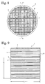
- ceramic honeycomb filters comprising porous ceramic honeycomb structures with both ends alternately sealed are used.
- a ceramic honeycomb structure 1 is substantially cylindrical (including an elliptic cross section) with partition walls 3 inside an outer wall 2 and a large number of cells (flow paths) 4 encircled thereby. As shown in Fig. 2(b), both ends of the flow paths 4 are alternately sealed by sealers 5a, 5b.
- the cleaning an exhaust gas by a honeycomb filter 10 is carried out as shown in Fig. 2(c).
- the exhaust gas 20a flows into the flow paths 4 of the honeycomb filter 10, passes through pores in the porous partition walls 3, and exits from the adjacent flow paths 4 as shown by 20b.
- Particulates in the exhaust gas are captured while passing through the pores of the partition walls 3.
- Particulates 30 are accumulated on an inner surface of each sealer 5 on an exit side.
- the captured particulates are burned off by a burner or an electric heater to regenerate the filter 10.
- particulates-capturing filter Important for such particulates-capturing filter are filter characteristics such as pressure loss, particulates-capturing efficiency, breakage resistance and melting-away resistance, etc. Though the pressure loss can be reduced by increasing the porosity and pore size of partition walls or by decreasing exhaust gas resistance, larger porosity and pore size leads to lower strength in the partition walls, resulting in low breakage resistance of the filter. Further, sealers formed at both ends of the honeycomb filter not only increase the pressure loss, but also lower the thermal shock resistance. It is thus difficult to satisfy both of the requirements of pressure loss and breakage resistance.
- JP 7-332064 A discloses a method for connecting pores three-dimensionally in sealers on the side of discharging an exhaust gas so that its porosity is 110-140% of the porosity of partition walls, to prevent the pressure loss of a ceramic honeycomb filter from being increased by sealers.
- the ceramic honeycomb filter of JP 7-332064 A as described in its Examples, has as small porosity as 45% in the honeycomb structure and as small porosity as 40-65% in the sealers, it suffers from large pressure loss. Because it does not have pores in sealers on an inlet side while it has pores in sealers on an exit side, an exhaust gas cannot pass through the sealers on the inlet side, resulting in insufficient effect of reducing the pressure loss.
- JP 8-281034 A discloses that thermal shock at the time of regeneration is concentrated in boundaries between sealed portions and unsealed portions in the partition walls of a honeycomb filter, and that such boundaries (corresponding to seal depth) should not be continuous on a line to prevent the honeycomb filter from being broken by such thermal shock.
- seal depth of the honeycomb filter is nonuniform, there is only a small effective area as a filter in portions having large seal depth, resulting in large pressure loss.
- filter areas differ from product to product, causing the problem that the resultant honeycomb filters do not have constant quality.
- there is weak adhesion strength between the sealers and the partition walls in portions having small seal depth the sealers are likely to peel off by the pressure of an exhaust gas or thermal shock, etc.
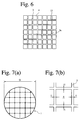
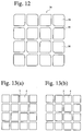
- a ceramic honeycomb structure has square cells (flow paths) as shown in Figs. 13(a) and (b), and the thickness of partition walls is substantially uniform throughout the ceramic honeycomb structure.
- a ceramic honeycomb structure having such structure has high strength in a direction in parallel with the partition walls, but its strength is low in a direction slanting to the partition walls. Accordingly, when used for catalyst converters and particulates-capturing filters, it is likely to suffer from cracking 13 in partition wall intersections by thermal shock or stress as shown in Fig. 6, resulting in breakage in a diagonal direction of cells.
- JP 55-147154 A discloses a technology of making partition walls near an outer wall thicker than partition walls inside them to increase the strength of the overall ceramic honeycomb structure.
- the partition walls are not thick in a core portion of the ceramic honeycomb structure, the partition wall intersections have uniform strength, so that cracking generated in the partition wall intersections continuously propagate through the core portion.
- JP 51-20435 B discloses that partition wall intersections are arcuately or linearly expanded to prevent that cracking is generated in the partition wall intersections on which stress is concentrated, and that catalytic reaction efficiency decreases in corners of flow paths (facing partition wall intersections) in which an exhaust gas does not flow smoothly.
- the strength of the partition wall intersections is uniform throughout the ceramic honeycomb structure, cracking generated by thermal shock or stress continuously propagates along the partition wall intersections.
- JP 61-129015 A discloses a filter for cleaning an exhaust gas having partition walls whose pores are composed of small pores having a pore diameter of 5-40 ⁇ m and large pores having a pore diameter of 40-100 ⁇ m, the number of the small pores being 5-40 times that of the large pores. Though it does not describe porosity, the porosity is calculated as 43-64% from an accumulated pores volume of 0.3-0.7 cm 3 /g, assuming that cordierite has a true specific gravity of 2.5.
- JP 61-54750 B discloses that by adjusting an open porosity and an average pore diameter, it is possible to design a filter from a high-capturing rate to a low-capturing rate. It describes that the preferred range of porosity is 33-90%.
- Japanese Patent 2,578,176 discloses a porous ceramic honeycomb filter having a long particulates-capturing time, the porosity being 40-55%, and the volume of pores having diameters of 2 ⁇ m or less being 0.015 cm 3 /g or less.
- JP 9-77573 A discloses a honeycomb structure having a high capturing rate, a low pressure loss and a low thermal expansion ratio, which has a porosity of 55-80% and an average pore diameter of 25-40 ⁇ m, pores in its partition walls being composed of small pores having diameters of 5-40 ⁇ m and large pores having diameters of 40-100 ⁇ m, and the number of small pores being 5-40 times that of large pores.
- porous ceramic honeycomb filters have high porosity, they inevitably have low strength.
- relatively flat powder such as carbon, graphite, etc. is used as a pore-forming material, pores have acute corners with large aspect ratios in their transverse cross sections. Therefore, stress concentration is likely to occur in the pores, causing decrease in the strength of the ceramic honeycomb structure.
- it is likely to be broken by thermal stress and shock, a mechanical fastening force at the time of assembling, vibration, etc.
- an object of the present invention is to provide a ceramic honeycomb filter having small pressure loss free from cracking due to thermal stress and thermal shock at the time of regenerating the filter, and a ceramic honeycomb structure used therefor.
- Another object of the present invention is to provide a ceramic honeycomb structure, in which cracking is less likely to propagate continuously in a diagonal direction of cells along partition wall intersections on which stress is concentrated.
- a further object of the present invention is to provide a high-strength ceramic honeycomb structure capable of being used as a particulates-capturing filter stably for a long period of time even with porosity of 50% or more.
- the first ceramic honeycomb filter of the present invention comprises a ceramic honeycomb structure having porous partition walls defining a plurality of flow paths for flowing an exhaust gas through the porous partition walls to remove particulates from the exhaust gas, wherein one end of each flow path is provided with a sealer, such that sealers of the flow paths in an inlet and an outlet of the ceramic honeycomb structure in a desired pattern; wherein the partition walls have thickness of 0.1-0.5 mm and a porosity of 50-80%; wherein the porosity of the sealers is larger than that of partition walls; and wherein the depth of the sealers is 3-15 mm.
- the second ceramic honeycomb filter of the present invention comprises a ceramic honeycomb structure having porous partition walls defining a plurality of flow paths for flowing an exhaust gas through the porous partition walls to remove particulates from the exhaust gas, wherein one end of each flow path is provided with a sealer, such that sealers of the flow paths in an inlet and an outlet of the ceramic honeycomb structure in a desired pattern; wherein the sealers have pores; and wherein at least part of the pores have substantially circular cross sections.
- the first ceramic honeycomb structure of the present invention has porous partition walls defining a plurality of flow paths, the partition walls forming the flow paths having nonuniform thickness.
- the average thickness T av , the maximum thickness T max and the minimum thickness T min of the partition walls preferably satisfy the conditions of T av /(T max - T min ) ⁇ 40.
- the second ceramic honeycomb structure of the present invention has porous partition walls defining a plurality of flow paths, a transverse cross section of each flow path being in a substantially square shape as a whole; a transverse cross section of at least part of flow paths being arcuate in one pair of opposing corners; and the one pair of opposing corners being larger than the other pair of opposing corners in a radius of curvature in each flow path.
- the ceramic honeycomb filter and structure according to a preferred embodiment of the present invention have a porosity of 50-80%, at least part of pores having cross section areas of 1,000 ⁇ m 2 or more in an arbitrary cross section of the partition walls having circular cross sections.
- the ceramic honeycomb filter and structure according to preferred embodiment of the present invention have a porosity of 50-80%, the percentage of the number of pores having aspect ratios of 2 or less being 60% or more among pores having cross section areas of 1,000 ⁇ m 2 or more in an arbitrary cross section of the partition walls.
- the percentage of the number of pores having roundness of 1-10 is preferably 50% or more among pores having cross section areas of 1,000 ⁇ m 2 or more in an arbitrary cross section of the partition walls.
- the porosity is preferably 60-70%.
- the average pore diameter of pores is preferably 10-40 ⁇ m.
- the thickness of the partition walls is preferably 0.1-0.5 mm, and the interval of the partition walls is preferably 1-3.5 mm.
- the preferred honeycomb filter and structure of the present invention have an A-axis compression strength of 3 MPa or more.
- the ceramic honeycomb filter and structure of the present invention are preferably made of cordierite having a main component chemical composition comprising 42-56% by mass of SiO 2 , 30-45% by mass of Al 2 O 3 , and 12-16% by mass of MgO.
- the ceramic honeycomb structure has a porosity of 50-80%, relatively large-diameter pores, specifically pores having cross section areas of 1,000 ⁇ m 2 or more in partition walls, contain those having substantially circular cross sections. This reduces the percentage of the number of pores having acute corners, making it unlikely that stress concentration occurs in the corners of pores, and thus resulting in improvement in the strength of the ceramic honeycomb structure.
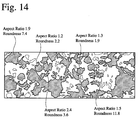
- the term "pores are substantially circular" in partition walls means that the roundness represented by the formula of length of circumference x length of circumference / (4 ⁇ x area of pore) is within a range of 1-10. In the case of a circle, the roundness is 1, and the roundness becomes larger as the cross section shape of a pore becomes deviated from a circle.
- the ceramic honeycomb structure When the porosity is less than 50%, the ceramic honeycomb structure has a large pressure loss when used as a diesel particulate filter, resulting in poor exhaust efficiency of diesel engines.
- the porosity when the porosity is more than 80%, there is too large a percentage of the number of pores even though relatively large-diameter pores have substantially circular cross sections, resulting in the ceramic honeycomb structure with insufficient strength and poor particulates-capturing efficiency. Accordingly, the ceramic honeycomb structure of the present invention has a porosity of 50-80%. The preferred range of the porosity is 60-70%.
- the percentage of the number of pores having roundness of 1-10 is preferably 50% or more among pores having cross section areas of 1,000 ⁇ m 2 or more (relatively large-diameter pores) in an arbitrary cross section of the partition walls.
- the percentage of the number of pores having roundness of 1-10 is preferably 50% or more among pores having cross section areas of 1,000 ⁇ m 2 or more (relatively large-diameter pores) in an arbitrary cross section of the partition walls.
- the percentage of the number of pores having aspect ratios of 2 or less is preferably 60% or more among pores having cross section areas of 1,000 ⁇ m 2 or more in an arbitrary cross section of the partition walls. This reduces the percentage of the number of pores having acute corners, making it unlikely that stress is concentrated on the pores, and thus resulting in the ceramic honeycomb structure with high strength.
- the pores existing in the ceramic honeycomb structure of the present invention preferably has an average pore diameter of 10-40 ⁇ m.
- the average diameter of the pores is less than 10 ⁇ m, it is likely to exhibit a large pressure loss when used as a diesel particulate filter, resulting in deterioration of the efficiency of diesel engines.
- the average pore diameter of the pores exceeds 40 ⁇ m, the strength of the ceramic honeycomb structure becomes too low, resulting in decrease in the particulates-capturing efficiency.
- the partition walls having thickness of 0.1-0.5 mm are formed at an interval of 1-3.5 mm.
- the thickness of the partition walls is more than 0.5 mm, or when the interval of the partition walls is less than 1 mm, it is likely to suffer from large pressure loss when used as a diesel particulate filter, failing to obtain sufficient filter characteristics.
- the thickness of the partition walls is less than 0.1 mm, or when the interval of the partition walls is more than 3.5 mm, the ceramic honeycomb structure is likely to have too low strength.
- the more preferred thickness of the partition walls is 0.2-0.4 mm, and the more preferred interval of the partition walls is 1.2-2.0 mm.
- the ceramic honeycomb structure of the present invention has an A-axis compression strength of 3 MPa or more.
- the ceramic honeycomb structure is not broken by thermal stress and thermal shock when used as a diesel particulate filter, a mechanical fastening force at the time of assembling, vibration, etc.
- the partition walls of the ceramic honeycomb filter have thickness of 0.1-0.5 mm and a porosity of 50-80%, the porosity of sealers is larger than that of partition walls, and the seal depth is 3-15 mm.
- This structure can satisfy two contradictory requirements of a low pressure loss and an excellent breakage resistance. Specifically, because partition walls have thickness of 0.1-0.5 mm and as high porosity as 50-80%, the exhaust gas passes through the partition walls with low resistance (pressure loss). Also, with the porosity of sealers larger than that of partition walls and with the seal depth of 3-15 mm, part of the exhaust gas passes through the sealers, resulting in decrease in pressure loss. Further, because the sealers have a small thermal capacity per a unit area, the sealers is unlikely to suffer from cracking even with a thermal shock.
- the porosity of sealers is larger than that of partition walls preferably by 5% or more, more preferably by 10% or more.
- the porosity of sealers is preferably 70-90%.
- the porosity of sealers is less than 70%, the percentage of an exhaust gas passing through the sealers is low, resulting in an insufficient effect of reducing pressure loss.
- the porosity of sealers is more than 90%, the sealers has insufficient strength, making it likely that chipping and cracking are generated particularly on both end surfaces at the time of canning and handling, and that large particulates in an exhaust gas cannot be captured.
- the porosity of sealers is particularly preferably 75%-85%. Incidentally, the porosity of sealers may be the same or different between the inlet and outlet sides as long as it is within the above range.
- the seal depth is less than 3 mm, adhesion strength is low between the sealers and the partition walls, making it likely that the sealers peel off by mechanical shock and thermal shock.
- the seal depth is more than 15 mm, the filter has a small effective area. Accordingly, the seal depth is 3-15 mm. The more preferred seal depth is 5-12 mm.
- substantially circular cross section means that the pores have aspect ratios (longest diameter / shortest diameter) of 2 or less. Because pores in the sealers in an arbitrary cross section have substantially circular cross sections, an exhaust gas can pass through the pores easily, and stress concentration can be reduced in the pores. Accordingly, it is possible to satisfy both of the contradictory requirements of low pressure loss and excellent breakage resistance.
- the percentage of the number of pores having aspect ratios of 2 or less among those having cross section areas of 1,000 ⁇ m 2 or more in the sealers is preferably 20% or more.
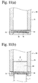
- the sealers formed on at least one end of the ceramic honeycomb structure preferably have concaved inner and/or outer surfaces.
- the sealers provided with concaved inner and/or outer surfaces resistance to an exhaust gas (pressure loss) can be reduced while keeping adhesion strength (breakage resistance) between the sealers and the partition walls.
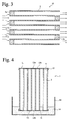
- Fig. 4 shows one example of methods for sealing the ends of a ceramic honeycomb structure.
- the masking films 12 After attaching masking films 12 to the ends of the ceramic honeycomb structure 1, the masking films 12 are provided with punctured portions (openings) 12b in a pattern as shown in Fig. 2.
- the ceramic honeycomb structure 1 thus provided with the masking films 12 is immersed in a slurry 14 for sealers in a container 16.
- ceramic materials with large particle size are used for the slurry 14, or pore-forming materials are added thereto.
- spherical pore-forming materials for instance, resin beads, preferably hollow resin beads
- the pore-forming materials are burned off by sintering.
- the slurry 14 penetrates into cells (flow paths) 4 of the ceramic honeycomb structure 1 immersed in the slurry 14 through the openings 12b of the masking film.
- the ceramic honeycomb structure 1 is turned upside down, so that the slurry 14 similarly penetrates into end portions of cells on the opposite side.
- the masking film 12 is peeled off.
- the seal depth of 3-15 mm can be obtained.
- the sealers are sintered to become integral with the partition walls.
- the partition walls of the ceramic honeycomb structure in the third embodiment have nonuniform thickness.
- the partition walls 3a, 3b of the ceramic honeycomb structure 1 have different thickness in a transverse cross section. Because the partition walls 3 has nonuniform thickness, partition wall intersections 3c have different strength from cell to cell, not constant in the ceramic honeycomb structure. Because no partition wall intersections 3c having substantially the same strength exist continuously, it is possible to prevent a phenomenon that cracking propagates continuously along the partition wall intersections 3c by thermal shock or stress, so that the ceramic honeycomb structure is broken in a diagonal direction of cells. Thus, this ceramic honeycomb structure has excellent thermal shock resistance.
- the partition wall intersections 3c shown in Fig. 5(c) have curved surfaces, it is advantageous in that it suffers from little stress concentration.
- the average thickness T av , the maximum thickness T max and the minimum thickness T min of the partition walls 3 preferably meet the relation of T av /(T max - T min ) ⁇ 40.
- the value of T av /(T max - T min ) indicates how nonuniform the thickness of the partition walls 3 is relative to its average thickness.
- the value of T av /(T max - T min ) is preferably 1-40, more preferably 2-30.
- T av /(T max - T min ) is less than 1, there is too large difference between the minimum wall thickness T min and the maximum wall thickness T max , resulting in poor speed balance of a molding blend discharged from slits of an orifice means of an extrusion-molding die, which leads to the bending or breakage of the resultant green bodies.
- the radii of curvature Ra, Rb of flow path corners, on which stress is concentrated are different between adjacent corners as shown in Fig. 10, so that adjacent partition wall intersections 103c, 113c have different strength. Accordingly, partition wall intersections having substantially the same strength do not align, resulting in large cracking resistance. Therefore, cracking is less likely to propagate even though excessive thermal or mechanical shock is applied to the ceramic honeycomb structure.
- a ratio of the radius of curvature Ra of one pair of opposing corners (slowly curved surfaces) to the radius of curvature Rb of the other pair of opposing corners (steeply curved surfaces) is preferably 1.5 or more.
- the ratio of Ra/Rb is less than 1.5, there is only small difference in strength between the adjacent partition wall intersections, resulting in small cracking resistance.
- each flow path 4 in a transverse cross section of each flow path 4, one pair of opposing arcuate corners facing large partition wall intersections 103c have a radius of curvature Ra, and the other pair of opposing corners facing small partition wall intersections 113c have a radius of curvature Rb.
- the radius of curvature Ra is larger than the radius of curvature Rb.
- the large partition wall intersections 103c and the small partition wall intersections 113c are arranged alternately in vertical directions.
- the partition wall intersections may be formed such that four corners of each flow path 4 have different radii of curvature.
- the ceramic honeycomb structure 1 Because the partition wall intersections having substantially the same strength are not adjacent to each other as described above, the ceramic honeycomb structure 1 has a large cracking resistance, thereby having improved thermal shock resistance strength and isostatic strength. Therefore, it is not likely that cracking is generated and propagates even though the ceramic honeycomb structure 1 is subjected to thermal shock by a high-temperature exhaust gas, or mechanical shock by vibration of engines, vibration due to contact with road surfaces, etc.
- Figs. 11 and 12 show an extrusion-molding die used for the production of the ceramic honeycomb structure 1, and an extrusion-molding method using it.
- the extrusion-molding die 50 comprises a die body 51 for receiving a molding blend 60, a holder 52 mounted onto a tip end of the die body 51, and an extrusion-molding orifice means 54 held in the holder 52.
- the orifice means 54 comprises a large number of pins 56 arranged in a lattice pattern, and gaps between the pins 56 are extrusion outlets 58 for the molding blend.
- Corners of each pins 56 have curved surfaces, and the radius of curvature Ra of one pair of opposing curved surfaces is larger than the radius of curvature Rb of the other pair of opposing corners.
- curved corners of the pins 52 may be formed by a grinding method, a discharge-working method, an electroplating method, an electro-etching method, etc.
- a ceramic material blend contained in the die body 51 is extruded through the extrusion outlets 58 in a lattice pattern by a plunger, etc. at pressure P, to form the ceramic honeycomb structure 1.
- the ceramic honeycomb filter of the present invention used as a filter for removing particulates from an exhaust gas mainly from diesel engines is constituted by a porous ceramic honeycomb structure and sealers, which are preferably formed by ceramic materials with excellent heat resistance.
- ceramic materials comprising at least one selected from the group consisting of cordierite, alumina, mullite, silicon nitride, silicon carbide and lithium aluminum silicate (LAS) as main components.
- cordierite is most preferable because it is inexpensive and has excellent heat resistance and corrosion resistance and low thermal expansion.
- cordierite it preferably has a main component chemical composition comprising 42-56% by mass of SiO 2 , 30-45% by mass of Al 2 O 3 , and 12-16% by mass of MgO.
- the ceramic honeycomb filter of the present invention When the amount of particulates captured by the ceramic honeycomb filter of the present invention has reached a predetermined level, the ceramic honeycomb filter is regenerated by an alternating regeneration method for burning particulates by a burner or an electric heater, a continuous regeneration method for continuously burning particulates by the action of a catalyst carried on the ceramic honeycomb structure, etc.
- cordierite-forming starting material powder comprising kaolin powder, calcined kaolin powder, alumina powder, aluminum hydroxide powder, silica powder and talc powder was mixed with a binder, a lubricant and spherical resin powder as a pore-forming material in predetermined amounts, and further fully mixed with water in a predetermined amount to form a plasticizable batch capable of being extrusion-molded to a honeycomb shape.
- honeycomb green bodies with square cross sections of flow paths and partition walls having various thickness and porosity were produced.
- Each green body was sintered after drying, to form a ceramic honeycomb structure of 150 mm in diameter and 150 mm in length.
- a pitch of partition walls was 1.5 mm in the resultant ceramic honeycomb structures, and the partition walls had various levels of thickness and porosity.
- the porosity of the partition walls were measured according to a mercury penetration method using Autopore III9410 available from Micromeritics.
- masking films 12 were attached to both end surfaces 11, 11 of each ceramic honeycomb structure with an adhesive, and each masking film 12 was punctured to have sealers 12a and openings 12b in a checkered pattern, such that only one end of each flow path 4 was sealed.
- one end 11 of the ceramic honeycomb structure 1 was immersed in a slurry 14 to a predetermined depth, to introduce the slurry 14 into flow paths 4 through the openings 12a of the masking film 12.
- the slurry 14 charged into its end portions was fully dried, and the ceramic honeycomb structure 1 was turned upside down to carry out immersion in the same slurry 14 and a drying treatment.
- the masking films 12 were peeled.
- the ceramic honeycomb structure 1 was provided with sealers 5 at both ends in predetermined patterns.
- the ceramic honeycomb structures 1 provided with sealers 5 were sintered in a batch-type sintering furnace (not shown), to obtain ceramic honeycomb filters 10 with sealers having various levels of porosity.
- the thickness and porosity of partition walls 3 and the porosity and depth of sealers 5 were measured.
- the thickness of the sealers was determined by inserting a metal rod of 0.8 mm in diameter into 25 cells in total, 5 cells along the X-axis and the Y-axis, respectively, from an open end of each cell in the ceramic honeycomb structure 1, and measuring the depth of this rod inserted into each sealer.
- the thickness of the sealers is an average value of the measured values at 25 points.
- each honeycomb filter 10 was evaluated with respect to pressure loss and thermal shock resistance as follows:
- thermal shock-resistant temperature Difference between the heating temperature and room temperature (25°C) when cracking appeared was called a thermal shock-resistant temperature.
- the evaluation standards of the thermal shock-resistant temperature were as follows: Incidentally, 600°C or more was regarded as "pass.”
- the partition walls had thickness within 0.1-0.5 mm and a porosity within 50-80%, and the sealers had larger porosity than that of the partition walls. Also, the seal depth was 3-15 mm. Accordingly, the evaluations of pressure loss and thermal shock resistance were good, and the overall evaluation was ⁇ . Particularly in Examples 4-7, because the porosity of the sealers was within a preferred range of 70-90%, the evaluation of pressure loss was o ⁇ .
- the thickness of partition walls was less than 0.1 mm in the honeycomb filter of Reference Example 1, its thermal shock resistance was poor. Because the honeycomb filter of Reference Example 2 had porosity of less than 50% in partition walls, with the porosity of sealers being smaller than that of the partition walls, it suffered from large pressure loss. Also, because it had a seal depth of less than 3 mm, it had a poor thermal shock resistance. Because the porosity of sealers was smaller than that of the partition walls in the honeycomb filter of Reference Example 3, it had a large pressure loss and a poor thermal shock resistance. Because the porosity of partition walls exceeded 80% in the honeycomb filter of Reference Example 4, it had a poor thermal shock resistance. Because the thickness of partition walls exceeded 0.5 mm in the honeycomb filter of Reference Example 5, it had a large pressure loss. Because the seal depth exceeded 15 mm in the honeycomb filter of Reference Example 6, it had a large pressure loss.
- a cordierite ceramic honeycomb filter 10 of 150 mm in outer diameter and 150 mm in length with 0.3-mm-thick partition walls at a pitch of 1.5 mm was produced in the same manner as in Example 1.
- the porosity of partition walls was 65%
- the porosity of sealers was 78%
- the seal depth was 10 mm.
- slurries 14 for sealers contained a spherical pore-forming material in the form of beads made of an acrylonitrile-methyl methacrylate copolymer resin in various amounts.
- each honeycomb filter 10 an arbitrary transverse cross section of a sealer was ground, and its SEM photograph was analyzed by the naked eye to determine whether or not there were pores having substantially circular cross sections.
- the SEM photograph was further analyzed by a commercially available image analysis software (Image-Pro Plus version 3.0 available from Media Cybernetics) to determine an aspect ratio of pore cross sections as illustrated in Fig. 14, thereby calculating among pores having cross section areas of 1,000 ⁇ m 2 or more, the percentage of the number of pores having aspect ratios of 2 or less was calculated.
- Example 8 yes 15 o ⁇ o ⁇ o ⁇ Example 9 yes 12 o ⁇ o ⁇ o ⁇ Example 10 yes 42 o ⁇ o ⁇ o ⁇ o ⁇ Example 11 yes 65 o ⁇ o ⁇ o ⁇ o ⁇ o ⁇ Example 12 no 0 o ⁇ ⁇ ⁇ Example 13 no 0 o ⁇ ⁇ ⁇
- honeycomb filters of Examples 8-11 had pores having substantially circular cross sections in their sealers, they had low pressure loss and excellent thermal shock resistance. Because the evaluation of the thermal shock resistance was o ⁇ or o ⁇ o ⁇ in any honeycomb filters, their overall evaluations were o ⁇ or o ⁇ o ⁇ . Particularly in the honeycomb filters of Example 10 and 11, the percentage of the number of pores having aspect ratios of 2 or less among those having cross section areas of 1,000 ⁇ m 2 or more in sealers was 20% or more, the evaluation of thermal shock resistance was o ⁇ o ⁇ , and their overall evaluation was o ⁇ o ⁇ . On the other hand, because the honeycomb filters of Examples 12 and 13 did not have pores having substantially circular cross sections in their sealers, their evaluation of thermal shock resistance was ⁇ , and thus their overall evaluation was ⁇ .
- a cordierite ceramic honeycomb filter 10 of 150 mm in outer diameter and 150 mm in length with 0.3-mm-thick partition walls at a pitch of 1.5 mm was produced in the same manner as in Example 1.
- the porosity of partition walls was 65%
- the porosity of sealers was 60%
- the seal depth was 10 mm.
- slurries 14 for sealers contained a spherical pore-forming material in the form of beads made of an acrylonitrile-methyl methacrylate copolymer resin in various amounts.
- each honeycomb filter 10 the presence or absence of pores having substantially circular cross sections and the percentage of the number of pores having aspect ratios of 2 or less were determined in the same manner as in Examples 8-13. Also, pressure loss and thermal shock resistance were evaluated in the same manner as in Example 1. The presence or absence of pores having substantially circular cross sections, the percentage of the number of pores having aspect ratios of 2 or less, the pressure loss, the thermal shock resistance and the overall evaluation are shown in Table 3. No.
- Example 14 yes 15 ⁇ ⁇ ⁇ Example 15 yes 12 ⁇ ⁇ ⁇ Example 16 yes 42 ⁇ o ⁇ o ⁇ Example 17 yes 65 ⁇ o ⁇ o ⁇ Reference Example 7 no 0 ⁇ ⁇ ⁇ Reference Example 8 no 0 ⁇ ⁇ ⁇
- honeycomb filters of Examples 14-17 had pores having substantially circular cross sections in their sealers, they had low pressure loss and excellent thermal shock resistance. Because the evaluation of the thermal shock resistance was ⁇ or o ⁇ in any honeycomb filters, their overall evaluations were ⁇ or o ⁇ . Particularly in the honeycomb filters of Example 16 and 17, the percentage of the number of pores having aspect ratios of 2 or less among those having cross section areas of 1,000 ⁇ m 2 or more in sealers was 20% or more, the evaluation of thermal shock resistance was o ⁇ , and their overall evaluation was o ⁇ . On the other hand, because the honeycomb filters of Reference Examples 7 and 8 did not have pores having substantially circular cross sections in their sealers, their evaluation of thermal shock resistance was ⁇ , and thus their overall evaluation was ⁇ .
- cordierite-forming starting material powder comprising kaolin powder, calcined kaolin powder, alumina powder, aluminum hydroxide powder, silica powder and talc powder was mixed with a binder, a lubricant and spherical resin powder as a pore-forming material in predetermined amounts. Water was added to the resultant mixture to form plasticizable molding batches.
- each molding batch was extrusion-molded to obtain a honeycomb green body having partition walls shown in Fig. 5(a).
- the resultant green body was sintered at 1400°C to obtain a cordierite ceramic honeycomb structure of 267 mm in outer diameter and 300 mm in length.
- Example 18 0.30 0.355 0.251 2.9 767
- Example 19 0.30 0.320 0.284 8.3 767
- Example 20 0.31 0.320 0.295 12 758
- Example 21 0.31 0.316 0.305 28 742
- Example 22 0.30 0.304 0.296 38 717
- Example 23 0.30 0.320 0.278 7.1 750
- Example 24 0.32 0.333 0.308 13 741
- Example 25 0.29 0.293 0.286 41 692
- Example 26 0.31 0.303 0.296 44 667
- Example 27 0.32 0.324 0.317 46 683
- the ceramic honeycomb structures of Examples 18-24 in which partition walls had nonuniform thickness, had thermal shock-resistant temperatures of 700°C or higher. This level of the thermal shock-resistant temperature was higher than that of Examples 25-27, in which T av /(T max - T min ) > 40.
- the thermal shock-resistant temperature of 700°C or higher is suitable for carriers for catalysts for cleaning exhaust gases from gasoline engines or filters for removing particulates from exhaust gases from diesel engines. Accordingly, the ceramic honeycomb structures are not substantially subjected to cracking and breakage due to thermal shock during operation.
- cordierite-forming starting material powder comprising kaolin powder, calcined kaolin powder, alumina powder, aluminum hydroxide powder, silica powder and talc powder was mixed with a binder, a lubricant and spherical resin powder as a pore-forming material in predetermined amounts. Water was added to the resultant mixture to provide a plasticizable molding batch.
- each cell had various radius of curvature as shown in Table 5, the radii of curvature of side surfaces of pins in an extrusion-molding orifice means were adjusted. Using this orifice means, each batch was extrusion-molded to obtain a honeycomb green body. The resultant green bodies were sintered at 1,400°C to obtain cordierite ceramic honeycomb structures 1 of 257 mm in outer diameter and 304 mm in length shown in Figs. 8-10. The partition walls of each ceramic honeycomb structure had an average thickness of 0.3 mm and a porosity of 60%, and the number of cells was 46.5 /cm 2 .
- each ceramic honeycomb structure was cut perpendicularly to its flow paths, and observed by a 100-times optical microscope to measure the radii of curvature of cell corners of the flow paths.
- breakage resistance to thermal shock and mechanical shock in each ceramic honeycomb structure 1
- the isostatic strength of each ceramic honeycomb structure 1 was measured by the following procedures according to the automobile standards (JASO) M505-87 by the Society of Automotive Engineers of Japan, Inc.
- a sample of each ceramic honeycomb structure 1 was prepared with 10-mm-thick aluminum plates attached to both end surfaces thereof and 2-mm-thick rubber sheets attached to an outer peripheral surface thereof. Each sample was charged into a pressure container, which was filled with water and pressurized to break the sample. The pressure at breakage was defined as isostatic strength.
- cordierite-forming starting material powder comprising kaolin powder, calcined kaolin powder, alumina powder, aluminum hydroxide powder, silica powder and talc powder was mixed with a binder, a lubricant and spherical resin powder as a pore-forming material in predetermined amounts. Water was added to the resultant mixture to prepare plasticizable molding batches. Each batch was extrusion-molded to a cylindrical honeycomb shape and dried.
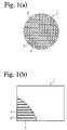
- the resultant cylindrical ceramic honeycomb green bodies of 143 mm in diameter and 152 mm in length were sintered at 1,350-1,440°C to obtain cordierite ceramic honeycomb structures 1 having partition walls 3 as shown in Figs. 1(a) and (b).
- the compositions of cordierite materials, molding conditions, sintering conditions, etc. were adjusted to produce the ceramic honeycomb structures 1 of Examples 32-35 with various pore characteristics and honeycomb partition wall structures.
- each ceramic honeycomb structure 1 The porosity and average pore diameter of each ceramic honeycomb structure 1 were measured according to a mercury penetration method using Autopore III9410 available from Micromeritics. It was observed by the naked eye on the SEM photograph of the ceramic honeycomb structure in an arbitrary transverse cross section, which was ground, whether or not there were pores having substantially circular cross sections among those having cross section areas of 1,000 ⁇ m 2 or more. The roundness of the pores having cross section areas of 1,000 ⁇ m 2 or more was determined by analyzing the data of SEM image by a commercially available image analysis software (Image-Pro Plus version 3.0 available from Media Cybernetics) as illustrated in Fig. 14.
- the A-axis compression strength was measured according to the standards M505-87, "Test Method of Ceramic Monolith Carriers for Exhaust-Gas-Cleaning Catalysts for Automobiles" determined by the Society of Automotive Engineers of Japan, Inc.
- each ceramic honeycomb structure was sealed as shown in Figs. 2(a) and (b) to obtain a porous ceramic honeycomb filter.
- the filter characteristics (breakage resistance, pressure loss and capturing efficiency) of each porous ceramic honeycomb filter were evaluated as follows. The results are shown in Table 6.
- the breakage resistance of each filter was evaluated by A-axis compression strength measured according to the standards M505-87, "Test Method of Ceramic Monolith Carriers for Exhaust-Gas-Cleaning Catalysts for Automobiles" determined by the Society of Automotive Engineers of Japan, Inc., by the following standards:
- the pressure loss was measured at a pressure loss test stand with air at a flow rate of 7.5 Nm 3 /minute flowing through each porous ceramic honeycomb filter, and evaluated by the following standards:
- carbon having a particle size of 0.042 ⁇ m carried by air at a flow rate of 7.5 Nm 3 /minute was caused to flow through each honeycomb filter for 2 hours in pressure loss test stand, such that the flow rate of carbon was 3 g/hour, and the amount of carbon captured by the honeycomb filter was measured.
- the evaluation standards of carbon-capturing efficiency were as follows:
- any ceramic honeycomb filters of Examples 32-35 had partition walls, in which pores having cross section areas of 1,000 ⁇ m 2 or more included those having substantially circular cross sections, there were high percentages of pores having roundness of 1-10. Accordingly, any ceramic honeycomb filters had breakage resistance whose evaluation was "pass.” They were also "pass” with respect to pressure loss and capturing efficiency, too, resulting in the overall evaluation of ⁇ or o ⁇ .
- any of the ceramic honeycomb filters of Examples 32-35 was "pass.”
- Example 6 The same cordierite-forming starting material powder as in Example 1 was mixed with a flat pore-forming material having a large aspect ratio such as graphite powder, carbon black powder, etc. in a predetermined amount, to produce various cordierite ceramic honeycomb structures 1, which were measured with respect to pores characteristics, the structure and A-axis compression strength of partition walls and filter characteristics for overall evaluation, in the same manner as in Examples 32-35. The results are shown in Table 6.
- Ceramic honeycomb structures with pore characteristics and partition wall structures shown in Table 7 were produced in the same manner as in Examples 32-35 except for controlling the compositions of cordierite-forming starting material powders, the shape and size of extrusion molding orifice means, extrusion molding conditions and sintering conditions.
- Each ceramic honeycomb structure was measured with respect to porosity, an average pore diameter, the shape of pores having cross section areas of 1,000 ⁇ m 2 or more, the roundness of pores having cross section areas of 1,000 ⁇ m 2 or more, and A-axis compression strength in the same manner as in Examples 32-35. The results are shown in Table 6.
- Each ceramic honeycomb structure was sealed at ends as shown in Figs. 2(a) and (b), to obtain a porous ceramic honeycomb filter.
- the filter characteristics (breakage resistance, pressure loss and capturing efficiency) of each porous ceramic honeycomb filter were evaluated in the same manner as in Examples 32-35. The results are shown in Table 6.
- any of the ceramic honeycomb structures of Examples 36-49 had an A-axis compression strength of 3MPa or more, and its breakage resistance was "pass."
- the ceramic honeycomb structures of Examples 38, 41, 44, 47 and 48 had extremely as high A-axis compression strength as more than 7 MPa. This is because of thick partition walls in Examples 38 and 47, a small porosity in Example 41, a small average pore diameter in Example 44, and a small pitch of partition walls in Example 48.
- any of the ceramic honeycomb structures of Examples 36-49 was "pass," and particularly the ceramic honeycomb structures of Examples 41, 45, 46 and 49 were excellent. This is because of a large porosity in Example 41, a large average pore diameter in Example 45, thin partition walls in Example 46, and a large pitch of partition walls in Example 49.
- any of the ceramic honeycomb structure filters of Examples 36-49 was "pass.”
- Reference Example 16 Because the ceramic honeycomb structure of Reference Example 16 had a porosity of more than 80%, its A-axis compression strength was as low as less than 3 MPa, despite the fact that the percentage of the number of pores having aspect ratios of 2 or more in transverse cross sections was 60% or more. Accordingly, Reference Example 16 was "fail" in breakage resistance and capturing efficiency.
- the ceramic honeycomb filter of the present invention has small pressure loss and excellent mechanical strength and thermal shock resistance free from cracking and melting due to thermal shock during its regeneration operation.
Priority Applications (2)
| Application Number | Priority Date | Filing Date | Title |
|---|---|---|---|
| EP20040021704 EP1491734B1 (fr) | 2001-12-03 | 2002-12-02 | Filtre céramique en nid d'abeilles |
| EP20060015683 EP1719882B1 (fr) | 2001-12-03 | 2002-12-02 | Filtre céramique en nid d'abeilles |
Applications Claiming Priority (6)
| Application Number | Priority Date | Filing Date | Title |
|---|---|---|---|
| JP2001368807 | 2001-12-03 | ||
| JP2001368807 | 2001-12-03 | ||
| JP2001395759 | 2001-12-27 | ||
| JP2001395759 | 2001-12-27 | ||
| JP2002068189 | 2002-03-13 | ||
| JP2002068189A JP4161292B2 (ja) | 2002-03-13 | 2002-03-13 | セラミックハニカム構造体 |
Related Child Applications (2)
| Application Number | Title | Priority Date | Filing Date |
|---|---|---|---|
| EP20040021704 Division EP1491734B1 (fr) | 2001-12-03 | 2002-12-02 | Filtre céramique en nid d'abeilles |
| EP20060015683 Division EP1719882B1 (fr) | 2001-12-03 | 2002-12-02 | Filtre céramique en nid d'abeilles |
Publications (3)
| Publication Number | Publication Date |
|---|---|
| EP1316686A2 true EP1316686A2 (fr) | 2003-06-04 |
| EP1316686A3 EP1316686A3 (fr) | 2003-08-13 |
| EP1316686B1 EP1316686B1 (fr) | 2007-09-05 |
Family
ID=27347900
Family Applications (3)
| Application Number | Title | Priority Date | Filing Date |
|---|---|---|---|
| EP20060015683 Expired - Lifetime EP1719882B1 (fr) | 2001-12-03 | 2002-12-02 | Filtre céramique en nid d'abeilles |
| EP20020026789 Expired - Lifetime EP1316686B1 (fr) | 2001-12-03 | 2002-12-02 | Filtre céramique en nid d'abeilles |
| EP20040021704 Expired - Lifetime EP1491734B1 (fr) | 2001-12-03 | 2002-12-02 | Filtre céramique en nid d'abeilles |
Family Applications Before (1)
| Application Number | Title | Priority Date | Filing Date |
|---|---|---|---|
| EP20060015683 Expired - Lifetime EP1719882B1 (fr) | 2001-12-03 | 2002-12-02 | Filtre céramique en nid d'abeilles |
Family Applications After (1)
| Application Number | Title | Priority Date | Filing Date |
|---|---|---|---|
| EP20040021704 Expired - Lifetime EP1491734B1 (fr) | 2001-12-03 | 2002-12-02 | Filtre céramique en nid d'abeilles |
Country Status (5)
| Country | Link |
|---|---|
| US (1) | US6890616B2 (fr) |
| EP (3) | EP1719882B1 (fr) |
| CN (2) | CN101240728B (fr) |
| AT (1) | ATE372449T1 (fr) |
| DE (3) | DE60233448D1 (fr) |
Cited By (11)
| Publication number | Priority date | Publication date | Assignee | Title |
|---|---|---|---|---|
| EP1650413A1 (fr) * | 2004-10-25 | 2006-04-26 | Ngk Insulators, Ltd. | Structure céramique nid d'abeille et méthode de fabrication |
| EP1707252A2 (fr) * | 2005-03-28 | 2006-10-04 | Ngk Insulators, Ltd. | Structure en nid d'abeilles |
| FR2894028A1 (fr) * | 2005-11-30 | 2007-06-01 | Saint Gobain Ct Recherches | Methode de selection d'une structure de filtration d'un gaz |
| FR2902423A1 (fr) * | 2006-06-19 | 2007-12-21 | Saint Gobain Ct Recherches | Ciment de jointoiement pour filtre a particules. |
| WO2008052837A1 (fr) * | 2006-11-03 | 2008-05-08 | Robert Bosch Gmbh | Élément de filtrage notamment destiné à filtrer des gaz d'échappement d'un moteur à combustion interne |
| WO2009016095A1 (fr) * | 2007-08-02 | 2009-02-05 | Robert Bosch Gmbh | Elément filtrant destiné à filtrer les gaz d'échappement d'un moteur à combustion interne |
| FR2928561A1 (fr) * | 2008-03-11 | 2009-09-18 | Saint Gobain Ct Recherches | Structure de filtration de gaz |
| US7901637B2 (en) | 2005-04-14 | 2011-03-08 | Benteler Automobiltechnik Gmbh | Device for exhaust emission purification for vehicles and production method thereof |
| US8388720B2 (en) | 2006-06-19 | 2013-03-05 | Saint Gobain Centre De Recherches Et D'etudes Europeen | Jointing cement containing hollow spheres, for a particle filter |
| EP2668990A4 (fr) * | 2012-02-24 | 2015-07-08 | Ngk Insulators Ltd | Structure en nid d'abeilles |
| EP1676622B2 (fr) † | 2003-10-23 | 2020-04-22 | Ibiden Co., Ltd. | Corps structure en nid d'abeille |
Families Citing this family (54)
| Publication number | Priority date | Publication date | Assignee | Title |
|---|---|---|---|---|
| JP2003040687A (ja) * | 2000-06-30 | 2003-02-13 | Ngk Insulators Ltd | ハニカムセラミックス構造体とその製造方法 |
| JP4197425B2 (ja) * | 2002-11-07 | 2008-12-17 | 日本碍子株式会社 | ハニカム構造体 |
| US20050050870A1 (en) * | 2003-03-03 | 2005-03-10 | Cheng Shi-Wai S. | Method and apparatus for filtering exhaust particulates |
| JP4767491B2 (ja) * | 2003-12-11 | 2011-09-07 | 日本碍子株式会社 | ハニカム構造体 |
| JP4526276B2 (ja) * | 2004-02-10 | 2010-08-18 | 株式会社キャタラー | フィルタ触媒およびその触媒層の解析方法 |
| DE102009008297A1 (de) * | 2009-02-10 | 2010-08-12 | Mann + Hummel Gmbh | Keramisches Filterelement mit Strukturelementen und Verfahren zur Hertellung |
| JP2006046200A (ja) * | 2004-08-05 | 2006-02-16 | Hitachi Ltd | ディーゼル内燃機関用排ガス浄化フィルタとその製造方法及び排ガス浄化装置 |
| WO2006092986A1 (fr) * | 2005-03-02 | 2006-09-08 | Ibiden Co., Ltd. | Ensemble de fibres inorganiques, procede destine a produire un ensemble de fibres inorganiques, structure en nid d’abeilles et procede destine a produire une structure en nid d’abeilles |
| EP1884275B1 (fr) * | 2005-05-23 | 2014-07-23 | NGK Insulators, Ltd. | Corps de structure alvéolaire |
| JPWO2007043245A1 (ja) * | 2005-10-12 | 2009-04-16 | イビデン株式会社 | ハニカムユニット及びハニカム構造体 |
| FR2893861B1 (fr) * | 2005-11-30 | 2008-01-04 | Saint Gobain Ct Recherches | Structure de filtration d'un gaz a base de sic de porosite de surface de paroi controlee |
| JP4788497B2 (ja) | 2005-12-27 | 2011-10-05 | 株式会社デンソー | 六角ハニカム構造体 |
| JP4709002B2 (ja) * | 2005-12-27 | 2011-06-22 | 株式会社デンソー | 六角セルハニカム構造体 |
| US8435320B2 (en) | 2006-08-30 | 2013-05-07 | Hitachi Metals, Ltd. | Ceramic honeycomb filter |
| FR2906159B1 (fr) * | 2006-09-27 | 2008-10-31 | Saint Gobain Ct Recherches | Element monolithique a coins renforces pour la filtration de particules |
| JP5150132B2 (ja) * | 2007-04-27 | 2013-02-20 | 日本碍子株式会社 | ハニカムフィルタシステム |
| CN101687132B (zh) * | 2007-05-04 | 2012-09-05 | 陶氏环球技术公司 | 改进的蜂窝式过滤器 |
| WO2009020835A2 (fr) | 2007-08-03 | 2009-02-12 | Errcive, Inc. | Corps poreux et procédés |
| US8297223B2 (en) * | 2007-10-02 | 2012-10-30 | Msp Corporation | Method and apparatus for particle filtration and enhancing tool performance in film deposition |
| JP5328174B2 (ja) * | 2008-02-20 | 2013-10-30 | 日本碍子株式会社 | 目封止ハニカム構造体 |
| US7849747B2 (en) * | 2008-03-07 | 2010-12-14 | Umicore Ag & Co. Kg | Flaw detection in exhaust system ceramic monoliths |
| DE102008039042B4 (de) * | 2008-08-21 | 2011-04-14 | Schott Ag | Substrat für einen Spiegelträger mit reduziertem Gewicht sowie Spiegel mit gewichtsreduziertem Spiegelträger |
| US8277743B1 (en) | 2009-04-08 | 2012-10-02 | Errcive, Inc. | Substrate fabrication |
| US8359829B1 (en) | 2009-06-25 | 2013-01-29 | Ramberg Charles E | Powertrain controls |
| EP2455153B1 (fr) | 2009-09-04 | 2018-10-31 | Hitachi Metals, Ltd. | Procédé de fabrication d'une structure céramique en nid-d'abeilles |
| CN102470310B (zh) * | 2009-10-08 | 2014-07-23 | 揖斐电株式会社 | 废气净化装置和废气净化方法 |
| US8926926B2 (en) * | 2009-11-25 | 2015-01-06 | GM Global Technology Operations LLC | Exhaust particulate management for gasoline-fueled engines |
| US9833932B1 (en) | 2010-06-30 | 2017-12-05 | Charles E. Ramberg | Layered structures |
| US8591622B2 (en) * | 2010-10-29 | 2013-11-26 | Corning Incorporated | Filter apparatus with porous ceramic plates |
| EP2692407B1 (fr) | 2011-03-31 | 2020-05-27 | NGK Insulators, Ltd. | Structure étanche en nid d'abeilles |
| JP5894577B2 (ja) | 2011-03-31 | 2016-03-30 | 日本碍子株式会社 | 目封止ハニカム構造体 |
| JP5916714B2 (ja) | 2011-03-31 | 2016-05-11 | 日本碍子株式会社 | 目封止ハニカム構造体及び排ガス浄化装置 |
| USD744078S1 (en) | 2011-12-07 | 2015-11-24 | Sumitomo Chemical Company, Limited | Particulate filter |
| MX2014011907A (es) * | 2012-04-05 | 2014-11-12 | Sumitomo Chemical Co | Estructura de panal de miel. |
| JP6068067B2 (ja) | 2012-09-06 | 2017-01-25 | 日本碍子株式会社 | 目封止ハニカム構造体 |
| WO2014138015A1 (fr) * | 2013-03-08 | 2014-09-12 | Corning Incorporated | Procédé de cuisson rapide pour céramiques |
| DE102013106612A1 (de) | 2013-06-25 | 2015-01-08 | Schott Ag | Werkzeugkrone und mit der Werkzeugkrone herstellbares Glaskeramik-Erzeugnis |
| US9808794B2 (en) * | 2013-09-23 | 2017-11-07 | Corning Incorporated | Honeycomb ceramic substrates, honeycomb extrusion dies, and methods of making honeycomb ceramic substrates |
| JP6492495B2 (ja) | 2014-01-27 | 2019-04-03 | 株式会社デンソー | 排ガス浄化フィルタ及びその製造方法 |
| WO2016106179A1 (fr) * | 2014-12-23 | 2016-06-30 | Porvair Plc | Filtre de métal fondu imprimé en 3d en céramique ayant une meilleure résistance à l'effritement |
| EP3275852B1 (fr) * | 2015-03-24 | 2022-01-12 | Hitachi Metals, Ltd. | Structure céramique en nid d'abeille et son procédé de fabrication |
| CN105413314B (zh) * | 2015-11-06 | 2017-04-05 | 中国第一汽车股份有限公司 | 颗粒过滤器的高活性材料的制备方法 |
| US10232300B2 (en) | 2015-11-11 | 2019-03-19 | Ngk Insulators, Ltd. | Plugged honeycomb structure |
| US10328376B2 (en) | 2016-03-30 | 2019-06-25 | Ngk Insulators, Ltd. | Plugged honeycomb structure |
| JP6615802B2 (ja) * | 2017-02-06 | 2019-12-04 | 日本碍子株式会社 | 目封止ハニカム構造体の製造方法 |
| US11534937B2 (en) | 2017-12-22 | 2022-12-27 | Corning Incorporated | Extrusion dies |
| CN108563615B (zh) * | 2018-04-09 | 2022-04-01 | 清华大学深圳研究生院 | 支柱绝缘子聚氨酯孔泡的评估方法 |
| CN112368465B (zh) * | 2018-05-04 | 2022-09-30 | 康宁股份有限公司 | 高均衡强度蜂窝结构及用于其的挤出模头 |
| WO2020047708A1 (fr) * | 2018-09-03 | 2020-03-12 | Corning Incorporated | Corps en nid d'abeilles comportant un matériau poreux |
| CN109519259A (zh) * | 2018-12-04 | 2019-03-26 | 北京今日蓝天科技有限公司 | 一种尾气净化用陶瓷催化器及尾气净化器 |
| CN110668797A (zh) * | 2019-11-04 | 2020-01-10 | 江西九岭新能源有限公司 | 过滤陶瓷载体及制备方法 |
| CN111744372B (zh) * | 2020-07-06 | 2022-06-28 | 广州市还原科技有限公司 | 一种多孔超滤陶瓷材料、含有该材料的制品及其制备 |
| CN111760387A (zh) * | 2020-07-27 | 2020-10-13 | 福建中弘环境科技有限公司 | 一种废气处理多级高效过滤装置 |
| JP2023536217A (ja) * | 2020-07-31 | 2023-08-24 | コーニング インコーポレイテッド | 開気孔率を有するセラミックビーズから作製されたセラミック物品 |
Citations (9)
| Publication number | Priority date | Publication date | Assignee | Title |
|---|---|---|---|---|
| US4233351A (en) * | 1978-05-18 | 1980-11-11 | Nippon Soken, Inc. | Ceramic honeycomb structure |
| EP0283220A1 (fr) * | 1987-03-14 | 1988-09-21 | Ngk Insulators, Ltd. | Corps céramiques structuraux en forme de nid d'abeilles |
| EP0354721A2 (fr) * | 1988-08-12 | 1990-02-14 | Ngk Insulators, Ltd. | Filtre poreux céramique en nid d'abeilles et son procédé de fabrication |
| JPH07332064A (ja) * | 1994-06-10 | 1995-12-19 | Ngk Insulators Ltd | 排ガスフィルタおよび排ガス処理装置 |
| JPH0977573A (ja) * | 1995-07-12 | 1997-03-25 | Denso Corp | ハニカム構造体及びその製造方法 |
| US5753339A (en) * | 1996-08-09 | 1998-05-19 | General Motors Corporation | Catalytic converter substrate with a plurality of cell groups having high and low thermal mass walls |
| EP0854123A1 (fr) * | 1996-08-07 | 1998-07-22 | Denso Corporation | Ceramique nid d'abeille et procede de fabrication |
| EP0867223A1 (fr) * | 1997-03-28 | 1998-09-30 | Ngk Insulators, Ltd. | Corps céramique en nid d'abeilles |
| EP1251247A1 (fr) * | 2001-04-19 | 2002-10-23 | Denso Corporation | Filtre de purification de gaz d'échappement |
Family Cites Families (29)
| Publication number | Priority date | Publication date | Assignee | Title |
|---|---|---|---|---|
| JPS5120435A (ja) | 1974-08-13 | 1976-02-18 | Mitsui Shipbuilding Eng | Jinkojipanyoshijichu |
| JPS54110189A (en) | 1978-02-17 | 1979-08-29 | Ngk Insulators Ltd | Ceramic honeycomb structure |
| JPS55147154A (en) | 1979-05-07 | 1980-11-15 | Ngk Spark Plug Co Ltd | High-strength honeycomb structure |
| US4329162A (en) * | 1980-07-03 | 1982-05-11 | Corning Glass Works | Diesel particulate trap |
| JPS57191421A (en) | 1981-05-19 | 1982-11-25 | Yamaha Motor Co Ltd | Engine with supercharger |
| US4423090A (en) * | 1982-02-02 | 1983-12-27 | General Motors Corporation | Method of making wall-flow monolith filter |
| JPS59224412A (ja) * | 1983-06-03 | 1984-12-17 | Nissan Motor Co Ltd | 内燃機関の排気フイルタ装置 |
| JPS61424A (ja) | 1984-06-12 | 1986-01-06 | Nippon Denso Co Ltd | セラミツクフイルタ |
| JPS6110917A (ja) | 1984-06-27 | 1986-01-18 | 株式会社東芝 | 交直変換装置の制御方法 |
| JPS6154750A (ja) | 1984-08-24 | 1986-03-19 | Toshiba Corp | 秘話通信方式 |
| JPH0244408B2 (ja) | 1984-09-03 | 1990-10-03 | Nippon Denki Kk | Ekookyanseragatasohokozofukuki |
| JPS61129015A (ja) * | 1984-11-24 | 1986-06-17 | Nippon Denso Co Ltd | 排出ガス浄化用フイルタおよびその製造方法 |
| DE3444472C1 (de) | 1984-12-06 | 1986-02-13 | Daimler-Benz Ag, 7000 Stuttgart | Abgasfilter fuer Dieselmotoren |
| SE451338B (sv) | 1985-07-05 | 1987-09-28 | Volvo Ab | Anordning for overladdning av en flercylindrig forbrenningsmotor |
| JPS6331517A (ja) | 1986-07-24 | 1988-02-10 | Asahi Glass Co Ltd | セラミツクフイルタ |
| CN1033455A (zh) * | 1987-12-09 | 1989-06-21 | 国家建筑材料工业局山东工业陶瓷研究设计院 | 堇青石质蜂窝陶瓷 |
| JP2693513B2 (ja) | 1988-08-30 | 1997-12-24 | 株式会社東芝 | アクティブマトリクス型液晶表示素子 |
| JP2562186B2 (ja) | 1988-09-21 | 1996-12-11 | 日本碍子株式会社 | 多孔質セラミックハニカム構造体の製法 |
| JP3400829B2 (ja) | 1992-07-23 | 2003-04-28 | 株式会社ノリタケカンパニーリミテド | モノリス型セラミックフィルター |
| JP2664119B2 (ja) | 1992-11-20 | 1997-10-15 | 日本碍子株式会社 | 曲りハニカム構造体 |
| JP2938740B2 (ja) * | 1993-12-14 | 1999-08-25 | 日本碍子株式会社 | コージェライト質セラミックフィルタとその製造方法 |
| JP3288536B2 (ja) | 1994-06-21 | 2002-06-04 | 日本碍子株式会社 | 排ガスフィルタおよびそれを使用した排ガス処理装置 |
| JP3012167B2 (ja) | 1995-04-12 | 2000-02-21 | 日本碍子株式会社 | 排ガス浄化フィルタおよびそれを用いた排ガス浄化装置 |
| JPH09276960A (ja) | 1996-04-17 | 1997-10-28 | Toyota Motor Corp | ハニカム体用波板の製造方法 |
| US6057030A (en) * | 1997-07-21 | 2000-05-02 | Kanebo Ltd. | Porous ceramic body and kiln furniture made from a porous ceramic body |
| JPH11128639A (ja) * | 1997-10-31 | 1999-05-18 | Asahi Glass Co Ltd | セラミックスフィルタ及びその製造方法 |
| JP4094771B2 (ja) | 1999-06-08 | 2008-06-04 | 日本碍子株式会社 | セラミックフィルタ用基材とその製造方法 |
| JP3756721B2 (ja) | 2000-03-24 | 2006-03-15 | 日本碍子株式会社 | 排ガス浄化用フィルター |
| US6764743B2 (en) * | 2001-05-01 | 2004-07-20 | Ngk Insulators, Ltd. | Porous honeycomb structure and process for production thereof |
-
2002
- 2002-12-02 DE DE60233448T patent/DE60233448D1/de not_active Expired - Lifetime
- 2002-12-02 EP EP20060015683 patent/EP1719882B1/fr not_active Expired - Lifetime
- 2002-12-02 DE DE2002618538 patent/DE60218538T2/de not_active Expired - Lifetime
- 2002-12-02 AT AT02026789T patent/ATE372449T1/de not_active IP Right Cessation
- 2002-12-02 US US10/307,360 patent/US6890616B2/en not_active Expired - Lifetime
- 2002-12-02 EP EP20020026789 patent/EP1316686B1/fr not_active Expired - Lifetime
- 2002-12-02 DE DE2002622225 patent/DE60222225T2/de not_active Expired - Lifetime
- 2002-12-02 EP EP20040021704 patent/EP1491734B1/fr not_active Expired - Lifetime
- 2002-12-03 CN CN2007101928879A patent/CN101240728B/zh not_active Expired - Lifetime
- 2002-12-03 CN CNB021524734A patent/CN100385096C/zh not_active Expired - Lifetime
Patent Citations (9)
| Publication number | Priority date | Publication date | Assignee | Title |
|---|---|---|---|---|
| US4233351A (en) * | 1978-05-18 | 1980-11-11 | Nippon Soken, Inc. | Ceramic honeycomb structure |
| EP0283220A1 (fr) * | 1987-03-14 | 1988-09-21 | Ngk Insulators, Ltd. | Corps céramiques structuraux en forme de nid d'abeilles |
| EP0354721A2 (fr) * | 1988-08-12 | 1990-02-14 | Ngk Insulators, Ltd. | Filtre poreux céramique en nid d'abeilles et son procédé de fabrication |
| JPH07332064A (ja) * | 1994-06-10 | 1995-12-19 | Ngk Insulators Ltd | 排ガスフィルタおよび排ガス処理装置 |
| JPH0977573A (ja) * | 1995-07-12 | 1997-03-25 | Denso Corp | ハニカム構造体及びその製造方法 |
| EP0854123A1 (fr) * | 1996-08-07 | 1998-07-22 | Denso Corporation | Ceramique nid d'abeille et procede de fabrication |
| US5753339A (en) * | 1996-08-09 | 1998-05-19 | General Motors Corporation | Catalytic converter substrate with a plurality of cell groups having high and low thermal mass walls |
| EP0867223A1 (fr) * | 1997-03-28 | 1998-09-30 | Ngk Insulators, Ltd. | Corps céramique en nid d'abeilles |
| EP1251247A1 (fr) * | 2001-04-19 | 2002-10-23 | Denso Corporation | Filtre de purification de gaz d'échappement |
Cited By (23)
| Publication number | Priority date | Publication date | Assignee | Title |
|---|---|---|---|---|
| EP1676622B2 (fr) † | 2003-10-23 | 2020-04-22 | Ibiden Co., Ltd. | Corps structure en nid d'abeille |
| US7488368B2 (en) | 2004-10-25 | 2009-02-10 | Ngk Insulators, Ltd. | Ceramic honeycomb structure and method of manufacturing the same |
| EP1650413B2 (fr) † | 2004-10-25 | 2011-10-05 | NGK Insulators, Ltd. | Structure céramique nid d'abeille et méthode de fabrication |
| EP1650413A1 (fr) * | 2004-10-25 | 2006-04-26 | Ngk Insulators, Ltd. | Structure céramique nid d'abeille et méthode de fabrication |
| EP1707252A2 (fr) * | 2005-03-28 | 2006-10-04 | Ngk Insulators, Ltd. | Structure en nid d'abeilles |
| EP1707252A3 (fr) * | 2005-03-28 | 2007-07-11 | Ngk Insulators, Ltd. | Structure en nid d'abeilles |
| US7901637B2 (en) | 2005-04-14 | 2011-03-08 | Benteler Automobiltechnik Gmbh | Device for exhaust emission purification for vehicles and production method thereof |
| EA014564B1 (ru) * | 2005-11-30 | 2010-12-30 | Сэн-Гобэн Сантр Де Решерш Э Д'Этюд Эропеен | Способ выбора структуры для фильтрации газа |
| FR2894028A1 (fr) * | 2005-11-30 | 2007-06-01 | Saint Gobain Ct Recherches | Methode de selection d'une structure de filtration d'un gaz |
| KR101298797B1 (ko) * | 2005-11-30 | 2013-08-27 | 생-고뱅 생트레 드 레체르체 에 데투드 유로삐엔 | 가스 필터 구조체의 선별 방법 |
| US8066798B2 (en) | 2005-11-30 | 2011-11-29 | Saint-Gobain Centre De Recherches Et D'etudes European | Method for selecting a gas filtering structure |
| WO2007063250A1 (fr) * | 2005-11-30 | 2007-06-07 | Saint-Gobain Centre De Recherches Et D'etudes Europeen | Methode de selection d'une structure de filtration d'un gaz |
| US8398736B2 (en) | 2006-06-19 | 2013-03-19 | Saint-Gobain Centre De Recherches Et D'etudes Europeen | Cement for particle filter |
| FR2902423A1 (fr) * | 2006-06-19 | 2007-12-21 | Saint Gobain Ct Recherches | Ciment de jointoiement pour filtre a particules. |
| WO2007148010A2 (fr) * | 2006-06-19 | 2007-12-27 | Saint-Gobain Centre De Recherches Et D'etudes Europeen | Ciment pour filtre a particules |
| US8388720B2 (en) | 2006-06-19 | 2013-03-05 | Saint Gobain Centre De Recherches Et D'etudes Europeen | Jointing cement containing hollow spheres, for a particle filter |
| WO2007148010A3 (fr) * | 2006-06-19 | 2008-03-20 | Saint Gobain Ct Recherches | Ciment pour filtre a particules |
| WO2008052837A1 (fr) * | 2006-11-03 | 2008-05-08 | Robert Bosch Gmbh | Élément de filtrage notamment destiné à filtrer des gaz d'échappement d'un moteur à combustion interne |
| WO2009016095A1 (fr) * | 2007-08-02 | 2009-02-05 | Robert Bosch Gmbh | Elément filtrant destiné à filtrer les gaz d'échappement d'un moteur à combustion interne |
| WO2009115762A3 (fr) * | 2008-03-11 | 2009-12-10 | Saint-Gobain Centre De Recherches Et D'etudes Europeen | Structure de filtration de gaz |
| WO2009115762A2 (fr) * | 2008-03-11 | 2009-09-24 | Saint-Gobain Centre De Recherches Et D'etudes Europeen | Structure de filtration de gaz |
| FR2928561A1 (fr) * | 2008-03-11 | 2009-09-18 | Saint Gobain Ct Recherches | Structure de filtration de gaz |
| EP2668990A4 (fr) * | 2012-02-24 | 2015-07-08 | Ngk Insulators Ltd | Structure en nid d'abeilles |
Also Published As
| Publication number | Publication date |
|---|---|
| US6890616B2 (en) | 2005-05-10 |
| CN100385096C (zh) | 2008-04-30 |
| DE60233448D1 (de) | 2009-10-01 |
| CN1424493A (zh) | 2003-06-18 |
| CN101240728B (zh) | 2012-07-04 |
| DE60218538D1 (de) | 2007-04-12 |
| EP1719882B1 (fr) | 2009-08-19 |
| CN101240728A (zh) | 2008-08-13 |
| US20030165662A1 (en) | 2003-09-04 |
| DE60222225T2 (de) | 2008-06-12 |
| EP1316686B1 (fr) | 2007-09-05 |
| EP1491734B1 (fr) | 2007-02-28 |
| EP1719882A1 (fr) | 2006-11-08 |
| DE60222225D1 (de) | 2007-10-18 |
| EP1491734A1 (fr) | 2004-12-29 |
| DE60218538T2 (de) | 2007-11-08 |
| ATE372449T1 (de) | 2007-09-15 |
| EP1316686A3 (fr) | 2003-08-13 |
Similar Documents
| Publication | Publication Date | Title |
|---|---|---|
| EP1491734B1 (fr) | Filtre céramique en nid d'abeilles | |
| EP1293241B1 (fr) | Filtre en nid d'abeilles en céramique | |
| US11033885B2 (en) | Ceramic honeycomb structure and its production method | |
| US8283282B2 (en) | Ceramic structure and process for producing the same | |
| KR100632161B1 (ko) | 세라믹 하니컴 구조체 | |
| EP1493724B1 (fr) | Materiau poreux et son procede de production | |
| EP2343113B1 (fr) | Structure en nid d'abeilles | |
| JP2006516528A (ja) | コージエライトセラミック体および方法 | |
| EP1790407A1 (fr) | Filtre à nids d abeille poreux | |
| EP2070576A1 (fr) | Structure céramique en nid d'abeille et son procédé de fabrication | |
| EP2737946B1 (fr) | Corps de catalyseur en nid d'abeille | |
| WO2009145910A1 (fr) | Nid d'abeille poreux à basse contre-pression et procédé pour le produire | |
| JP3506334B2 (ja) | セラミックハニカムフィルタ | |
| JP7289813B2 (ja) | セラミックス多孔体及びその製造方法、並びに集塵用フィルタ | |
| JP4577752B2 (ja) | セラミックハニカムフィルタ | |
| JP2003001029A (ja) | 多孔質セラミックハニカムフィルタ | |
| JP2004250324A (ja) | セラミックハニカム構造体の製造方法、およびコージェライト化原料 | |
| CN101307704B (zh) | 陶瓷蜂巢式结构件 | |
| CN114950029A (zh) | 多孔质蜂窝结构体及其制造方法 |
Legal Events
| Date | Code | Title | Description |
|---|---|---|---|
| PUAI | Public reference made under article 153(3) epc to a published international application that has entered the european phase |
Free format text: ORIGINAL CODE: 0009012 |
|
| AK | Designated contracting states |
Designated state(s): AT BE BG CH CY CZ DE DK EE ES FI FR GB GR IE IT LI LU MC NL PT SE SI SK TR |
|
| AX | Request for extension of the european patent |
Extension state: AL LT LV MK RO |
|
| PUAL | Search report despatched |
Free format text: ORIGINAL CODE: 0009013 |
|
| AK | Designated contracting states |
Designated state(s): AT BE BG CH CY CZ DE DK EE ES FI FR GB GR IE IT LI LU MC NL PT SE SI SK TR |
|
| AX | Request for extension of the european patent |
Extension state: AL LT LV MK RO |
|
| 17P | Request for examination filed |
Effective date: 20040211 |
|
| 17Q | First examination report despatched |
Effective date: 20040311 |
|
| AKX | Designation fees paid |
Designated state(s): AT BE BG CH CY CZ DE DK EE ES FI FR GB GR IE IT LI LU MC NL PT SE SI SK TR |
|
| RIN1 | Information on inventor provided before grant (corrected) |
Inventor name: SUWABE, HIROHISA Inventor name: OTSUBO, YASUHIKO Inventor name: TOKUDOME, OSAMU Inventor name: OKAZAKI, SHUNJI |
|
| GRAP | Despatch of communication of intention to grant a patent |
Free format text: ORIGINAL CODE: EPIDOSNIGR1 |
|
| GRAS | Grant fee paid |
Free format text: ORIGINAL CODE: EPIDOSNIGR3 |
|
| GRAA | (expected) grant |
Free format text: ORIGINAL CODE: 0009210 |
|
| AK | Designated contracting states |
Kind code of ref document: B1 Designated state(s): AT BE BG CH CY CZ DE DK EE ES FI FR GB GR IE IT LI LU MC NL PT SE SI SK TR |
|
| REG | Reference to a national code |
Ref country code: GB Ref legal event code: FG4D |
|
| REG | Reference to a national code |
Ref country code: CH Ref legal event code: EP |
|
| REF | Corresponds to: |
Ref document number: 60222225 Country of ref document: DE Date of ref document: 20071018 Kind code of ref document: P |
|
| REG | Reference to a national code |
Ref country code: IE Ref legal event code: FG4D |
|
| PG25 | Lapsed in a contracting state [announced via postgrant information from national office to epo] |
Ref country code: FI Free format text: LAPSE BECAUSE OF FAILURE TO SUBMIT A TRANSLATION OF THE DESCRIPTION OR TO PAY THE FEE WITHIN THE PRESCRIBED TIME-LIMIT Effective date: 20070905 Ref country code: ES Free format text: LAPSE BECAUSE OF FAILURE TO SUBMIT A TRANSLATION OF THE DESCRIPTION OR TO PAY THE FEE WITHIN THE PRESCRIBED TIME-LIMIT Effective date: 20071216 |
|
| PG25 | Lapsed in a contracting state [announced via postgrant information from national office to epo] |
Ref country code: LI Free format text: LAPSE BECAUSE OF FAILURE TO SUBMIT A TRANSLATION OF THE DESCRIPTION OR TO PAY THE FEE WITHIN THE PRESCRIBED TIME-LIMIT Effective date: 20070905 Ref country code: CH Free format text: LAPSE BECAUSE OF FAILURE TO SUBMIT A TRANSLATION OF THE DESCRIPTION OR TO PAY THE FEE WITHIN THE PRESCRIBED TIME-LIMIT Effective date: 20070905 Ref country code: AT Free format text: LAPSE BECAUSE OF FAILURE TO SUBMIT A TRANSLATION OF THE DESCRIPTION OR TO PAY THE FEE WITHIN THE PRESCRIBED TIME-LIMIT Effective date: 20070905 |
|
| NLV1 | Nl: lapsed or annulled due to failure to fulfill the requirements of art. 29p and 29m of the patents act | ||
| PG25 | Lapsed in a contracting state [announced via postgrant information from national office to epo] |
Ref country code: BE Free format text: LAPSE BECAUSE OF FAILURE TO SUBMIT A TRANSLATION OF THE DESCRIPTION OR TO PAY THE FEE WITHIN THE PRESCRIBED TIME-LIMIT Effective date: 20070905 |
|
| REG | Reference to a national code |
Ref country code: CH Ref legal event code: PL |
|
| ET | Fr: translation filed | ||
| PG25 | Lapsed in a contracting state [announced via postgrant information from national office to epo] |
Ref country code: NL Free format text: LAPSE BECAUSE OF FAILURE TO SUBMIT A TRANSLATION OF THE DESCRIPTION OR TO PAY THE FEE WITHIN THE PRESCRIBED TIME-LIMIT Effective date: 20070905 Ref country code: GR Free format text: LAPSE BECAUSE OF FAILURE TO SUBMIT A TRANSLATION OF THE DESCRIPTION OR TO PAY THE FEE WITHIN THE PRESCRIBED TIME-LIMIT Effective date: 20071206 |
|
| PG25 | Lapsed in a contracting state [announced via postgrant information from national office to epo] |
Ref country code: SK Free format text: LAPSE BECAUSE OF FAILURE TO SUBMIT A TRANSLATION OF THE DESCRIPTION OR TO PAY THE FEE WITHIN THE PRESCRIBED TIME-LIMIT Effective date: 20070905 Ref country code: PT Free format text: LAPSE BECAUSE OF FAILURE TO SUBMIT A TRANSLATION OF THE DESCRIPTION OR TO PAY THE FEE WITHIN THE PRESCRIBED TIME-LIMIT Effective date: 20080206 Ref country code: CZ Free format text: LAPSE BECAUSE OF FAILURE TO SUBMIT A TRANSLATION OF THE DESCRIPTION OR TO PAY THE FEE WITHIN THE PRESCRIBED TIME-LIMIT Effective date: 20070905 |
|
| PG25 | Lapsed in a contracting state [announced via postgrant information from national office to epo] |
Ref country code: SE Free format text: LAPSE BECAUSE OF FAILURE TO SUBMIT A TRANSLATION OF THE DESCRIPTION OR TO PAY THE FEE WITHIN THE PRESCRIBED TIME-LIMIT Effective date: 20071205 |
|
| PLBE | No opposition filed within time limit |
Free format text: ORIGINAL CODE: 0009261 |
|
| STAA | Information on the status of an ep patent application or granted ep patent |
Free format text: STATUS: NO OPPOSITION FILED WITHIN TIME LIMIT |
|
| PG25 | Lapsed in a contracting state [announced via postgrant information from national office to epo] |
Ref country code: MC Free format text: LAPSE BECAUSE OF NON-PAYMENT OF DUE FEES Effective date: 20071231 Ref country code: DK Free format text: LAPSE BECAUSE OF FAILURE TO SUBMIT A TRANSLATION OF THE DESCRIPTION OR TO PAY THE FEE WITHIN THE PRESCRIBED TIME-LIMIT Effective date: 20070905 |
|
| 26N | No opposition filed |
Effective date: 20080606 |
|
| PG25 | Lapsed in a contracting state [announced via postgrant information from national office to epo] |
Ref country code: IE Free format text: LAPSE BECAUSE OF NON-PAYMENT OF DUE FEES Effective date: 20071203 |
|
| PG25 | Lapsed in a contracting state [announced via postgrant information from national office to epo] |
Ref country code: EE Free format text: LAPSE BECAUSE OF FAILURE TO SUBMIT A TRANSLATION OF THE DESCRIPTION OR TO PAY THE FEE WITHIN THE PRESCRIBED TIME-LIMIT Effective date: 20070905 |
|
| PG25 | Lapsed in a contracting state [announced via postgrant information from national office to epo] |
Ref country code: SI Free format text: LAPSE BECAUSE OF FAILURE TO SUBMIT A TRANSLATION OF THE DESCRIPTION OR TO PAY THE FEE WITHIN THE PRESCRIBED TIME-LIMIT Effective date: 20070905 |
|
| PG25 | Lapsed in a contracting state [announced via postgrant information from national office to epo] |
Ref country code: CY Free format text: LAPSE BECAUSE OF FAILURE TO SUBMIT A TRANSLATION OF THE DESCRIPTION OR TO PAY THE FEE WITHIN THE PRESCRIBED TIME-LIMIT Effective date: 20070905 |
|
| PG25 | Lapsed in a contracting state [announced via postgrant information from national office to epo] |
Ref country code: BG Free format text: LAPSE BECAUSE OF FAILURE TO SUBMIT A TRANSLATION OF THE DESCRIPTION OR TO PAY THE FEE WITHIN THE PRESCRIBED TIME-LIMIT Effective date: 20071205 Ref country code: LU Free format text: LAPSE BECAUSE OF NON-PAYMENT OF DUE FEES Effective date: 20071202 |
|
| PG25 | Lapsed in a contracting state [announced via postgrant information from national office to epo] |
Ref country code: TR Free format text: LAPSE BECAUSE OF FAILURE TO SUBMIT A TRANSLATION OF THE DESCRIPTION OR TO PAY THE FEE WITHIN THE PRESCRIBED TIME-LIMIT Effective date: 20070905 |
|
| PG25 | Lapsed in a contracting state [announced via postgrant information from national office to epo] |
Ref country code: IT Free format text: LAPSE BECAUSE OF NON-PAYMENT OF DUE FEES Effective date: 20071231 |
|
| REG | Reference to a national code |
Ref country code: FR Ref legal event code: PLFP Year of fee payment: 14 |
|
| REG | Reference to a national code |
Ref country code: FR Ref legal event code: PLFP Year of fee payment: 15 |
|
| REG | Reference to a national code |
Ref country code: FR Ref legal event code: PLFP Year of fee payment: 16 |
|
| PGFP | Annual fee paid to national office [announced via postgrant information from national office to epo] |
Ref country code: DE Payment date: 20211102 Year of fee payment: 20 Ref country code: GB Payment date: 20211028 Year of fee payment: 20 Ref country code: FR Payment date: 20211109 Year of fee payment: 20 |
|
| REG | Reference to a national code |
Ref country code: DE Ref legal event code: R071 Ref document number: 60222225 Country of ref document: DE |
|
| REG | Reference to a national code |
Ref country code: GB Ref legal event code: PE20 Expiry date: 20221201 |
|
| PG25 | Lapsed in a contracting state [announced via postgrant information from national office to epo] |
Ref country code: GB Free format text: LAPSE BECAUSE OF EXPIRATION OF PROTECTION Effective date: 20221201 |