EP1315660B1 - Continuous haulage system - Google Patents
Continuous haulage system Download PDFInfo
- Publication number
- EP1315660B1 EP1315660B1 EP00974152A EP00974152A EP1315660B1 EP 1315660 B1 EP1315660 B1 EP 1315660B1 EP 00974152 A EP00974152 A EP 00974152A EP 00974152 A EP00974152 A EP 00974152A EP 1315660 B1 EP1315660 B1 EP 1315660B1
- Authority
- EP
- European Patent Office
- Prior art keywords
- belt
- haulage system
- continuous haulage
- continuous
- hook
- Prior art date
- Legal status (The legal status is an assumption and is not a legal conclusion. Google has not performed a legal analysis and makes no representation as to the accuracy of the status listed.)
- Expired - Lifetime
Links
Images


Classifications
-
- B—PERFORMING OPERATIONS; TRANSPORTING
- B65—CONVEYING; PACKING; STORING; HANDLING THIN OR FILAMENTARY MATERIAL
- B65G—TRANSPORT OR STORAGE DEVICES, e.g. CONVEYORS FOR LOADING OR TIPPING, SHOP CONVEYOR SYSTEMS OR PNEUMATIC TUBE CONVEYORS
- B65G15/00—Conveyors having endless load-conveying surfaces, i.e. belts and like continuous members, to which tractive effort is transmitted by means other than endless driving elements of similar configuration
- B65G15/30—Belts or like endless load-carriers
- B65G15/32—Belts or like endless load-carriers made of rubber or plastics
- B65G15/42—Belts or like endless load-carriers made of rubber or plastics having ribs, ridges, or other surface projections
-
- B—PERFORMING OPERATIONS; TRANSPORTING
- B65—CONVEYING; PACKING; STORING; HANDLING THIN OR FILAMENTARY MATERIAL
- B65G—TRANSPORT OR STORAGE DEVICES, e.g. CONVEYORS FOR LOADING OR TIPPING, SHOP CONVEYOR SYSTEMS OR PNEUMATIC TUBE CONVEYORS
- B65G15/00—Conveyors having endless load-conveying surfaces, i.e. belts and like continuous members, to which tractive effort is transmitted by means other than endless driving elements of similar configuration
- B65G15/08—Conveyors having endless load-conveying surfaces, i.e. belts and like continuous members, to which tractive effort is transmitted by means other than endless driving elements of similar configuration the load-carrying surface being formed by a concave or tubular belt, e.g. a belt forming a trough
-
- B—PERFORMING OPERATIONS; TRANSPORTING
- B65—CONVEYING; PACKING; STORING; HANDLING THIN OR FILAMENTARY MATERIAL
- B65G—TRANSPORT OR STORAGE DEVICES, e.g. CONVEYORS FOR LOADING OR TIPPING, SHOP CONVEYOR SYSTEMS OR PNEUMATIC TUBE CONVEYORS
- B65G15/00—Conveyors having endless load-conveying surfaces, i.e. belts and like continuous members, to which tractive effort is transmitted by means other than endless driving elements of similar configuration
- B65G15/30—Belts or like endless load-carriers
- B65G15/32—Belts or like endless load-carriers made of rubber or plastics
- B65G15/40—Belts or like endless load-carriers made of rubber or plastics troughed or tubular; formed with joints facilitating troughing
-
- B—PERFORMING OPERATIONS; TRANSPORTING
- B65—CONVEYING; PACKING; STORING; HANDLING THIN OR FILAMENTARY MATERIAL
- B65G—TRANSPORT OR STORAGE DEVICES, e.g. CONVEYORS FOR LOADING OR TIPPING, SHOP CONVEYOR SYSTEMS OR PNEUMATIC TUBE CONVEYORS
- B65G23/00—Driving gear for endless conveyors; Belt- or chain-tensioning arrangements
- B65G23/02—Belt- or chain-engaging elements
- B65G23/14—Endless driving elements extending parallel to belt or chain
-
- B—PERFORMING OPERATIONS; TRANSPORTING
- B65—CONVEYING; PACKING; STORING; HANDLING THIN OR FILAMENTARY MATERIAL
- B65G—TRANSPORT OR STORAGE DEVICES, e.g. CONVEYORS FOR LOADING OR TIPPING, SHOP CONVEYOR SYSTEMS OR PNEUMATIC TUBE CONVEYORS
- B65G39/00—Rollers, e.g. drive rollers, or arrangements thereof incorporated in roller-ways or other types of mechanical conveyors
- B65G39/10—Arrangements of rollers
- B65G39/12—Arrangements of rollers mounted on framework
-
- B—PERFORMING OPERATIONS; TRANSPORTING
- B65—CONVEYING; PACKING; STORING; HANDLING THIN OR FILAMENTARY MATERIAL
- B65G—TRANSPORT OR STORAGE DEVICES, e.g. CONVEYORS FOR LOADING OR TIPPING, SHOP CONVEYOR SYSTEMS OR PNEUMATIC TUBE CONVEYORS
- B65G2201/00—Indexing codes relating to handling devices, e.g. conveyors, characterised by the type of product or load being conveyed or handled
- B65G2201/04—Bulk
Definitions
- the present invention is generally directed to the removal of material from a mine site, specifically continuous haulage systems, and in particular to suspended continuous haulage systems.
- Run of Mine (ROM) material is defined as any free material from a mine, including both ore and waste material.
- ROM Run of Mine
- the material is removed by purpose built trucks, capable of transporting many tens of tonnes of material at a time.
- the ROM material is loaded onto the trucks, either from temporary stockpiles or directly from extraction.
- the trucks then travel from the pit to the waste material dump or to the ore crushing plant, depending on the quality of material for the particular load.
- a conveyor system needs to be tensioned between drive drums, which provide the motivating drive, thus being a substantial contributor to the lack of deviation. Therefore, it is normal, for such systems, to spend a considerable amount of time selecting the path to ensure an uninterrupted straight path is achievable.
- a further problem is the size limitation of the system.
- the belt of the conveyor system is susceptible to severe damage from large, angular rocks, partly because of the punching shear force established between the sharpness of the rocks on the belt and the support from underneath, as a result of the impact of the rocks.
- Such systems are associated with In-Pit Crushing plants, to reduce the size and weight of individual rocks to be transported.
- Such systems are limited to rock sizes of less than 300 mm, and thus any material to be removed from the pit must be crushed to a suitable size.
- An alternative form of conveyor system is the so-called suspended belt system, as exemplified by US 4,915,213 .
- This system marketed under the name SICON, includes a belt that is tear-drop shaped, and open at the top.
- the longitudinal edges of the belt, adjacent to each other at the top of the tear-drop shape, are mounted on continuous cables tensioned between end drums that drive the belt through friction. Material is loaded by separating the cables, allowing the belt to open. After loading, the cables are brought together, containing the material not unlike a sack. It has been found that such an arrangement cannot be used on a significant slope without slippage of material thereon.
- a continuous haulage system including a belt adapted to convey material, said belt being suspended from a plurality of discrete supporting means by hanging members located along each opposing longitudinal edge of said belt, wherein the hanging member has a hook-shaped cross-section.
- the belt may be both flexible in the longitudinal and lateral direction, such that it can at least substantially form a supporting tube for conveying material therein when the supporting idlers converge towards each other for the haulage of material. Loading and unloading is also effected by diverging from each other, and thus opening the belt.
- the hook-shaped profile may be provided along a reinforced portion at each longitudinal edge of the belt.
- the hook-shaped profile serves the dual function of being retainable on the idlers during service and making the belt readily detachable for maintenance.
- the key advantage to the hook-shaped profile is the capacity for a translational degree of freedom.
- the action is more than merely a "ball in socket" motion, which is typical of similar curve profiles (often spherical).
- the area of contact between the idler face and the hook-shaped profile can vary substantially along the curvi-linear path of the hook-shaped profile.
- this action permits a very wide scope to accommodate vertical and horizontal curves along the line of haulage.
- the belt may be continuous, with the hook-shaped profile extending along its entire length.
- the belt may be a segmented belt, that is, a belt formed as a plurality of discrete portions joined in series, but still retaining the hook-shaped profile along the longitudinal edge of the portions.
- the "train" of segmented sections functions in the same manner as a continuous belt.
- sections may be added or removed for lengthening the belt or replacing damaged sections.
- sections may be replaced by linking elements, such as a chain or rod, where the volume of material to be transporter is small, but individual rocks are of such a size as to require a large capacity belt.
- the extra degree of freedom permits increased rock sizes as compared with the conventional conveyor belt systems and suspended belt systems. Whereas such systems are restricted in the size of rock that can be transported, the ability of the hook-shaped profile to rotate and translate permit rocks of greater than 300 mm in diameter to be accommodated within the belt under normal conditions.
- the extra degree of freedom also provides for the belt to open further to permit the capacity of the belt to be utilized to a greater degree than conventional systems.
- conventional systems tend to impart adverse loads to other elements in the system, the present invention avoids such problems.
- this extra capacity also has a synergistic effect with regard to vertical mobility.
- the system provides for travel up inclined surfaces. To travel up such a slope requires the run of mine material to be stable within the belt. By increasing the volume of material held, there is a tendency for the material to consolidate, thus providing a mass of material that tends to act in a unitary fashion. Known as “bridging”, when material is loaded into the belt, and the opening closed, the material is compressed by the closing walls of the belt. This compression tends to consolidate the material, preventing the material from flowing easily. When loaded to a significant proportion of the belt's capacity, the material actually binds up such that no flow is possible.
- This effect is known as a problem in situations where material is required to flow, such as loading hoppers, feed bins, ore passes and so forth.
- the present invention uses the consolidation to advantage by controlling the effect. Subsequently, when unloading the belt, the opening is widened and the belt loosens the material, permitting the material to flow once again.
- the hook-shaped profile has the advantage of being self cleaning. With the concave aspect of the profile being directed downwards, any detritus that is adhering to the idlers and is transferred to the belt, will tend to dislodge quickly, falling away harmlessly, rather than merely infiltrating the equipment completely. This self cleaning action is further assisted by the any particular portion of the belt only being in intermittent contact with the idler support.
- the hook-shaped profile would also include a reverse curve, whereby a second idler may provide a downward reaction to the concave face of the reverse curve extremity of the longitudinal edge of the belt.
- each longitudinal edge of the continuous belt may have a second hook, as a mirror image of the first, and thus at the same level but directed away from the first hook, but having the concave portion of the hook also directed downward, as does the first.
- This embodiment permits the use of variable arrangement of idlers for extra stability, drive, loading or unloading characteristic or other associated purpose.
- a second hook may be placed in the same alignment as the first, but directly below the first, and thus accommodate a bank of idlers one above the other.
- a continuous haulage system including a belt adapted to convey material, said belt being suspended from supporting means by hanging members located along each opposing longitudinal edge of said belt, wherein the hanging member has a hook-shaped cross-section, and further including at least one drive means adapted to impart a driving force to said belt by engaging a receiving means located along each opposing longitudinal edge of the belt.
- the drive means may include a caterpillar drive, having a continuous elongate drive surface, contacting a portion of the belt or a carrier of the belt, to impart a driving force by friction or by mating surfaces between the caterpillar drive and the belt, or belt carrier.
- the caterpillar drive may include a series of sprockets.
- the continuous belt may be a chain having the elongate drive surface bonded to it.
- the continuous belt may be a chain drive rather than driven through friction.
- Said drive system may include a plurality of caterpillar drives placed intermediate between the extreme ends of the continuous haulage system.
- the drive system may be associated with idler units mounted into frames, said idlers not having drive capability, that act to support the driven belt and are also placed intermediately between the extreme ends of the continuous haulage system.
- each end may be located an undriven pulley unit, mounted into a frame, that acts to support and "return" the belt.
- the drive means and idler units may be part of a continuous frame work.
- the drive and idler units may each be mounted within discrete frames. In the case of discrete frames, these may be linked to permit a pivotal movement between each frame.
- the discrete frames may be isolated from each other, there being no direct contact between adjacent frames.
- the belt may be driven, without the need of high tensioning between drums as in conventional end drum drive systems.
- a belt driven by the caterpillar drive does not require tensioning.
- the fixity of the end drive drums was a major determinant in the inextensibility of the conventional conveyor system, in that, the point of extraction is continually moving but the drive drums are unable to be moved with ease.
- the invention permits the addition of further discrete idler unit frames to the continuous haulage system, as well as further drive units if required for extra drive. Also, being undriven the pulley units at the ends are readily moveable. Thus, by lengthening the belt, and adding new units, the continuous haulage system is able to be extended by adopting the drive system.
- a belt for a continuous haulage system said belt having a hook-shaped profile along its longitudinal edge, wherein the belt may be corrugated, said corrugation propagating longitudinally along the length of the belt.
- the corrugated belt provides for two distinct advantages over the prior art. Firstly, with regard to the continuous haulage system located on an inclined surface, the corrugations further assist in retaining material by providing a series of barriers at discrete distances along the belt length. Thus when the belt is being used under capacity, and the binding effect of a large volume of material is less effective, the addition of the corrugations provides interference for the backward slide of the material, and thus the material may be retained.
- each corrugation acts as an articulating element, further enhancing the flexibility of the belt in both the vertical and horizontal direction.
- the corrugations may be inclined at an angle to the vertical axis of the belt. This provides for an effectively vertical corrugation when the belt is inclined up a slope.
- each individual corrugation will provide an interference extending along a significant length of the belt. As a portion of the belt containing material climbs an inclined surface, the material will shift downward. This shift of material will be limited by the corrugations.
- the ability of the material to "bridge" will be enhanced, as the bridging effect will involve more material per corrugation, and thus provide an increased ability to restrain the flow of material as the belt becomes inclined.
- the corrugations may extend along a portion only of the cross-section periphery, being symmetrical about the centreline of the cross-section and encompassing the curved base of the cross-section.
- each corrugation may vary along the length of the corrugation, with the greatest depth occurring at the base of the belt, and symmetrically reducing in size on either side of the base.
- a continuous haulage system including a belt, said belt having a hook-shaped profile along its longitudinal edge, said continuous haulage system being driven by a drive system, wherein the drive system includes at least one drive means located along a the length of the belt, contacting a portion of the belt or a carrier of the belt, to impart a driving force by mating surfaces between the drive means and the belt, or belt carrier.
- the drive means may include a caterpillar drive having a continuous drive surface.
- the drive system provides for an extension of the continuous haulage system, in the event such an extension also requires a deviation around an obstacle, the articulation of the idler units frames and the hook to idler connection provide sufficient flexibility for the belt and the supporting frame to vary from a straight line around the obstacle.
- This flexibility also permits vertical curvature, such that the haulage system can negotiate vertical inclines.
- conventional suspended systems are unable to travel up vertical inclines of more than about 30o, as the material will tend to slide backwards. This is due to the relatively small volume of material within the belt, which can readily slide longitudinally down the belt.
- the ability for the material to shift more than a marginal amount is restricted. Thus, apart from minor settling, the material is unable to move, allowing the continuous haulage system to travel up inclined slopes far exceeding those of conventional systems.
- a continuous haulage system including a belt adapted to convey material, said belt being suspended from supporting means by hanging members located along each opposing longitudinal edge of said belt, wherein the hanging member has a hook-shaped cross-section, and further including an articulated support system including a plurality of support frames each being pivotal in the horizontal plane and also in the vertical plane.
- a feature of having each frame pivotally adjustable, when used as a series of similarly adjustable frames in combination with a continuous haulage system, is to provide for a fully articulated system that is adjustable to accommodate obstacles and traverse inclined surfaces.
- a second feature of the above described system is the extensibility of the system through the addition of further individual units.
- these features provide a two part procedure for the tracking of the moving extraction point within a mine.
- An example is a mobile excavator on a track traversing an excavation face within a mine. As the excavator is constantly moving whilst removing material from the face, any system for removing the run of mine material must likewise move.
- the continuous haulage system may be established before commencing the excavation process.
- the line may have several meanders before presenting the loading point of the continuous haulage system in proximity to the commencement point of the excavation.
- the effective distance of the haulage line would be substantially less than the actual length.
- the loading point may be readily moved to follow the excavator.
- the articulation in at least one of the frames accommodates the movement, and thus the continuous haulage system self aligns as the meanders are straightened.
- the effective length may be extended, without affecting the overall length of the haulage line.
- This process of advancing the loading point can be repeated until the effective length and actual length are the same.
- the calculation of the actual length may be influenced by the length of the excavation face, or similar.
- additional articulated frames can be added, and a corresponding length of belt added. Whilst not as readily achieved as the articulation of the individual frames, when required, the actual length of the haulage line can be increased by lengthening the belt and adding additional frames.
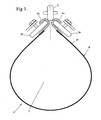
- Figure 1 shows a belt 1 in the closed state for a suspended continuous haulage system, wherein the belt 1 is supported intermittently by a series of idler sets , made up from two opposing and inclined idlers 3a and 3b contacting the belt at two hook shaped profiles 4a and 4b longitudinally and continuously extending for the full length of the belt 1.
- a central idler 5 bears downwards on the hooks 4a and 4b, providing a reaction for the generally upward directed idlers 3a and 3b, and thus clamping the hooks in a three way grip between all the idlers 3 and 5.
- the hooks are located along each of the longitudinal edges of a strip 6 made from a reinforced rubber compound, designed to resist abrasion and local shear.
- the hooks comprise shaped metal elements to form the hook shape, and reinforced by a plurality of steel cables, or other composite construction, running longitudinally and parallel with the strip 6.
- the hooks are integrally connected 10 to the strip 6 to form the belt 1.
- the continuous haulage system functions by transporting material within the enclosed space 7 of the belt 1.
- the belt is driven in a continuous loop, and supported intermittently by a series of idler sets , which act to both support and to keep closed, the confining the material within the space 7 and also applying a lateral distributed load through the rubber strip 6 to the material within.
- the material tends to compact partially, assisting in the transport of the material.
- FIG. 2 shows the hook 4a to idler 3a arrangement in detail.
- the hook 4a has the concave portion of the hook 4a directed generally downwards, allowing the generally upwardly directed idler 4a to engage the hook 4a.
- the angle at which the hook 4a is generally directed will vary away from substantially vertical to a position where the concave portion of the hook 4a may be directed downward and outward at an angle of up to 45o to the vertical.
- the idler 3a as part of the three way support is directed upwards and out of the vertical by up to 45o.
- the hooks 4a and 4b are pressed together, holding the belt 1 in the closed position.
- the idlers 3a, 3b and 5 must prevent any translation freedom of the hooks 4a and 4b.
- the special arrangement of the hooks and idlers (3a, 3b, 4a, 4b and 5) permit a single rotational freedom, such that the hook may be rotated within the plane of the belt 1 cross section.
- This rotational degree of freedom is achieved by the dissimilar curves of the hook 4a and idler 3a.
- the curve 8 of the concave surface of the hook 4a is of significantly different radius than the curve 9 of the idler 3a.
- a compatible curve arrangement between the hook 4a and the idler 3a would emulate a ball and socket arrangement, and thus the two curves 8 and 9 would have a surface contact. Whilst this would permit the hook 4a to rotate freely, if not connected to the strip 6, the strip 6 lacks clearance from the idler set 2 to allow the belt 1 to gain its full capacity.
- the curves 8 and 9 dissimilar the relative motion of the hook 4a and idler 3a requires the contact between the surfaces 8 and 9 to move freely, and thus both rotation and a type of translation occurs.
- the hook 4a rotates and translates to a balanced position, allowing the extra capacity to be realized.
- the increased rotation and translation is demonstrated by the angle 11 from the vertical.
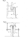
- Figure 3 shows an alternative embodiment of the hook arrangement, wherein the first hook portion has an extension in the form of a reverse curve 4c.
- first hook portion has the concave surface directed generally downwards
- reverse curve 4c portion has the concave surface directed upwards.
- the upwardly directed surface is adapted to make contact with a further idler 3c placed adjacent, and generally parallel to, the first 3b.
- first idler 3b provides the upward reaction to support the belt 6 through the first hook portion
- the second idler 3c provides a downward reaction.
- An advantage provided by the reverse curve 4c includes stability during loading and unloading.
- a feature of the present invention is the ability of the hook and idler to rotate and translate relative to each other so as to fully utilize the belt capacity to held material. However, there may be instances where this movement is not required, such as at loading and unloading.
- By providing a second point of reaction parallel with the first a broad support is provided at the hook portion, limiting or preventing rotation, and thus provide the required stability.
- Figure 4 shows a further alternative embodiment of the hook arrangement, wherein the single hook portion is replaced by a dual hook portion 4d, that is, two hook portions, the second being a mirror image of the first.
- the dual hook 4d has the further advantage of increasing the load carrying capacity of the belt 6 at that portion.
- this embodiment has an advantage during the loading phase. As a result of the impact of material entering the belt 6, the loads to be resisted by the support system are higher than at any time during the transport of the material.
- the loading carrying capacity is doubled at a time when such extra capacity is required.
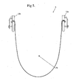
- Figure 5 shows the belt 1 in the open position ready for loading and unloading of the material.
- a differing idler set 12a and 12b is required.
- the open position requires the opposing idlers 12a and 12b to diverge, which separate the longitudinal edges of the belt 1, and thus opens the belt 1.
- material may be loaded directly into the space 7b through a hopper (not shown) or other means.
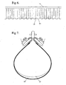
- FIG 6 shows an alternative possible arrangement of the belt 1 in elevation, providing a longitudinal orientation to the continuous haulage system.
- the belt 1 displays corrugations 13 and 14 placed longitudinally along the belt 1 in spaced relation to each other.
- the corrugations 13 and 14, in this case, are vertically disposed, however, variant where the corrugations 13 and 14 are inclined may also be contemplated.
- the corrugations 13 and 14 are formed by providing increased reinforcement in the raised portion 13 of the belt, such that sharp rocks being loaded or transported by the belt 1 contact the raised corrugations 13, having vastly increased abrasion resistance as compared with the troughs 14 of the corrugation.
- this provides for the raised portion 13 to have replaceable inserts (not shown) providing the reinforcement.
- the belt 1 remains protected from rock damage by a continual replacement of the protective inserts.
- Figure 7 shows the corrugations 13 and 14 in cross section, and provides insight into the corrugations second most valuable feature.
- the belt 1 when closed tends to compact the material. This compaction tends to bind the material through an enhanced cohesion, and thus limiting movement of the material during transportation.
- the compaction is selectively applied to the material, as well as enhanced in these locations, and thereby enhancing the compaction effect.
- FIG 8 shows an alternative arrangement of the belt 1.
- the belt of Figures 6 and 7 showed a belt 1 having corrugations 14 directed at right angles to the axis of the belt 1
- the corrugations 14a of Figure 8 are inclined at an angle 15 to the vertical.
- the inclination of such corrugations 14a are useful when the continuous haulage system is positioned up an inclined surface. With the "bridging" effect, the conveyed material is held in a semi-consolidated mass. When travelling up an inclined slope, gravity will tend to push the material back down the belt. Whilst this action can assist consolidation, any weakness in the mass can also disturb the consolidation.
- inclined corrugations 14a further assistance against this back sliding is provided, thus enhancing the characteristics of the system.
- Figure 8 further shows the corrugations only extending partially up the belt 1 to a line 16. Applicable to both inclined 14a and non-inclined 14 corrugations, the degree to which the corrugations 14a extend upward provides only an incremental benefit passed a certain line 16. This line 16 will vary with conditions, materials, moisture content, inclination etc. Hence, when designing a system, the line 16 can be used to optimise the system if a full height of corrugation 14a is not required.
- Figure 9 shows the belt 1 being driven by the caterpillar drive 17, which includes a continuous belt 18 actuated by a drive roller 20 with the continuous belt 18 traveling around a series of caterpillar idlers 19.
- the hook 4 of the belt 1 is driven by being threaded between the continuous belt 18 and a series of pinch idlers 21.
- the drive along the continuous belt 18 is assisted by the adjustable pressure applied between the pinch idlers 21 and the caterpillar idlers 19, through the continuous belt 18.
- the drive 17 may be based on friction
- the reaction pressure which controls the friction drive is adjustable under adverse conditions.
- the caterpillar drive 17 may include a series of sprockets in place of the drive roller 19 and caterpillar idlers 19.
- the continuous belt 18 may be a chain having a drive surface bonded to it.
- the continuous belt 18 may be a chain drive rather than friction.
- the continuous belt 18 may be profiled or knurled 22 and a complimentary knurling 23 on the concave surface of the hook 4.
- the continuous haulage system 1 may be configured such that the drive system 17 is independent of environmental conditions which may limit the effectiveness of friction based drives, by providing a drive system similar in concept to a sprocket and chain arrangement.
- the profiling, or knurling 22 can be effected by the provision of teeth, projections or other raised portions, so as to provide a better grip.
- a meshing or engagement between the two elements 18 & 24 can be achieved. This meshing can ensure the driving force imparted to the hook 4 is through a positive drive rather than relying on friction.
- Figure 10 shows the drive system 17 and the belt 1 in cross section, with the continuous belt 18 in contact with the hooks 4a and 4b.
- the orientation of the drive system 17, in relation to the angle to the vertical is identical to that of the idlers 3a and 3b.
- the drive system 17 is located within a framework such that the drive system 17 also supports the belt 1 in the same manner as idlers 3a and 3b located within a support frame (not shown).
- the incorporation of the drive system 17 along the path of the continuous haulage system is non-intrusive and with the continuous haulage system being flexible enough to not be restricted in the number of drive systems that can be incorporated.
- FIG 11 shows a plan view of the entire continuous haulage system 24.
- the system comprises a hopper 25 that material is loaded into for delivery to the belt 1.
- Material may be loaded by any number of means, such as from laden trucks, direct from a mine face or from a crushing plant.
- the material from the hopper 25 travels along the belt 1 which is supported by a series of support frames 26, which use either idler sets 2 or drive systems 14 to contact the hooks 4a and 4b of the belt 1.
- Each of the support frames 26 have a pivotal system incorporated such that a restricted degree of angular movement in the horizontal and vertical planes, as well as torsionally about a longitudinal axis of the continuous haulage system 1, is permissible.
- Adjacent frames 26 can be either directly connected or be isolated from each other. In the case of the direct connection, the connection provides for further degrees of angular movement. In either case, the position of the frames 26 can be adjusted such that the path of the continuous haulage system 24 can adopt a selectively curvi-line
- This degree of movement permits, therefore, the relative position of the hopper 25 and the unloading point 28 to vary by advancing the hopper 25 in accordance with movement of, say, the point of extraction of the ROM material.
- the hopper 25 As the hopper 25 is advanced, at least one of the frames 26 will accommodate the movement of the continuous haulage path.
- the articulation in the, at least one, frame permits the system to self align, permitting straightening.
- the position of the hopper 25 may be conveniently and readily adjusted to match this movement.
- the required maximum length of the continuous haulage system 24 can be placed, with substantial meanders incorporated in the path, and thus have the relative position of the hopper 25 and the unloading point 28 relatively small at commencement of operations.
- the meanders within the path may be straightened until the furthest position of the ideal loading point is reached. At this point the continuous haulage system 24 path will be straight.
- Figure 12 shows a segmented belt 6a arrangement, as an alternative to the continuous belt.
- the continuous haulage system may be designed for a maximum capacity, is may be less advantageous to operate the system at this high capacity when only a portion is actually being removed. This the system must accommodate the lesser capacity. Despite the lower capacity, the actual size of the rocks being removed is unlikely to vary, and so the belt must still be able to encapsulate large rocks.
- the volume of the belt is maintained, but the total volume of material being convened can be controlled by managing the proportion of actual belt per metre length of the system as a whole.
Landscapes
- Mechanical Engineering (AREA)
- Engineering & Computer Science (AREA)
- Belt Conveyors (AREA)
- Structure Of Belt Conveyors (AREA)
- Management, Administration, Business Operations System, And Electronic Commerce (AREA)
- Treatment Of Fiber Materials (AREA)
- Jib Cranes (AREA)
- Underground Structures, Protecting, Testing And Restoring Foundations (AREA)
- Advancing Webs (AREA)
- Threshing Machine Elements (AREA)
- Jet Pumps And Other Pumps (AREA)
- Vehicle Body Suspensions (AREA)
- Chain Conveyers (AREA)
- Folding Of Thin Sheet-Like Materials, Special Discharging Devices, And Others (AREA)
- Farming Of Fish And Shellfish (AREA)
- Medicines Containing Plant Substances (AREA)
- Lifting Devices For Agricultural Implements (AREA)
- Supply And Distribution Of Alternating Current (AREA)
Applications Claiming Priority (3)
| Application Number | Priority Date | Filing Date | Title |
|---|---|---|---|
| AUPQ401299 | 1999-11-12 | ||
| AUPQ4012A AUPQ401299A0 (en) | 1999-11-12 | 1999-11-12 | Continous haulage system |
| PCT/AU2000/001358 WO2001036303A1 (en) | 1999-11-12 | 2000-11-06 | Continuous haulage system |
Publications (3)
| Publication Number | Publication Date |
|---|---|
| EP1315660A1 EP1315660A1 (en) | 2003-06-04 |
| EP1315660A4 EP1315660A4 (en) | 2008-07-02 |
| EP1315660B1 true EP1315660B1 (en) | 2010-10-27 |
Family
ID=3818157
Family Applications (1)
| Application Number | Title | Priority Date | Filing Date |
|---|---|---|---|
| EP00974152A Expired - Lifetime EP1315660B1 (en) | 1999-11-12 | 2000-11-06 | Continuous haulage system |
Country Status (17)
| Country | Link |
|---|---|
| US (1) | US7032744B1 (enExample) |
| EP (1) | EP1315660B1 (enExample) |
| JP (1) | JP2003514733A (enExample) |
| CN (1) | CN1297455C (enExample) |
| AT (1) | ATE486029T1 (enExample) |
| AU (2) | AUPQ401299A0 (enExample) |
| BR (1) | BR0015529B1 (enExample) |
| CA (1) | CA2391383C (enExample) |
| DE (1) | DE60045161D1 (enExample) |
| DK (1) | DK1315660T3 (enExample) |
| ES (1) | ES2355349T3 (enExample) |
| MX (1) | MXPA02004757A (enExample) |
| NZ (1) | NZ518837A (enExample) |
| PE (1) | PE20010943A1 (enExample) |
| RU (1) | RU2266856C2 (enExample) |
| WO (1) | WO2001036303A1 (enExample) |
| ZA (1) | ZA200204655B (enExample) |
Families Citing this family (20)
| Publication number | Priority date | Publication date | Assignee | Title |
|---|---|---|---|---|
| US7051868B2 (en) * | 2004-02-19 | 2006-05-30 | Atbc, Llc | Prestressed tubular belt and method for making |
| RU2286938C1 (ru) * | 2005-03-05 | 2006-11-10 | Общество с ограниченной ответственностью "Конвейер-Старт" | Конвейер с подвесной лентой |
| CA2642740C (en) * | 2006-04-07 | 2015-05-12 | Michael Pietsch | Coupling arrangement and system for continuous haulage conveyor |
| RU2328434C1 (ru) * | 2006-12-21 | 2008-07-10 | Государственное образовательное учреждение высшего профессионального образования "Санкт-Петербургский государственный горный институт им. Г.В. Плеханова (технический университет)" | Конвейер с подвесной лентой |
| RU2328435C1 (ru) * | 2006-12-25 | 2008-07-10 | Государственное образовательное учреждение высшего профессионального образования "Санкт-Петербургский государственный горный институт им. Г.В. Плеханова (технический университет)" | Ленточный конвейер с подвесной лентой |
| CA2733640A1 (en) * | 2008-08-11 | 2010-02-18 | Technological Resources Pty Limited | Mining system |
| WO2010017581A1 (en) * | 2008-08-11 | 2010-02-18 | Technological Resources Pty. Limited | Mining system |
| WO2012009765A1 (en) * | 2010-07-23 | 2012-01-26 | Newcastle Innovation Limited | Rail conveyor system |
| CN102295134B (zh) * | 2011-05-11 | 2013-05-22 | 李超 | 轨道吊挂型输送机 |
| EP2830978A1 (en) | 2012-03-30 | 2015-02-04 | P. Ellegaard A/S | Flexible closed belt conveyor |
| NZ630567A (en) * | 2012-04-03 | 2015-07-31 | Dw Technologies Pty Ltd | Conveyor system |
| AU2013313034A1 (en) * | 2012-09-10 | 2015-04-30 | Bulk Solutions Pty Ltd | A roof mountable support system |
| MX369582B (es) * | 2013-09-18 | 2019-11-13 | Flexlink Ab | Soporte de cadena de transportadora. |
| AU2014362272B2 (en) * | 2013-12-12 | 2019-09-19 | Niche Innovations Pty Ltd. | Conveyor system and method for transporting material |
| WO2017109543A1 (en) | 2015-12-22 | 2017-06-29 | Arcelormittal | Method and system for determining the mass of feedstock on a conveyor |
| CN106697770A (zh) * | 2016-11-30 | 2017-05-24 | 宁波洛克依奈尔智能科技有限公司 | 一种轨道吊挂式输送机 |
| CN109230213A (zh) * | 2018-09-29 | 2019-01-18 | 芜湖中义玻璃有限公司 | 一种玻璃瓶生产用原料输送装置 |
| CN111115109B (zh) * | 2018-10-30 | 2022-04-26 | 河北昊德橡塑有限公司 | 一种橡胶传送带及其制备方法 |
| CN113979008B (zh) * | 2021-10-21 | 2022-12-13 | 国铠惰封装备股份有限公司 | 基于对合密闭管带的密闭输送装置及qhse运行方法 |
| FR3154108A1 (fr) * | 2023-10-16 | 2025-04-18 | René Brunone | Convoyeur à bande pour forte granulométrie |
Family Cites Families (29)
| Publication number | Priority date | Publication date | Assignee | Title |
|---|---|---|---|---|
| GB190405611A (en) * | 1904-03-08 | 1905-03-08 | Robert Mayo Catlin | Improvements in Belt Conveyors. |
| US826312A (en) * | 1904-04-12 | 1906-07-17 | Robert Mayo Catlin | Belt conveyer. |
| US843018A (en) * | 1905-04-22 | 1907-02-05 | James Alexander Jamieson | Conveyer. |
| SU81252A1 (ru) * | 1947-09-08 | 1948-11-30 | Я.Ф. Финкель | Ленточный транспортер с замыкаемым в трубу несущим органом |
| US3381799A (en) * | 1966-10-14 | 1968-05-07 | Transporta | Conveyors |
| JPS4635160Y1 (enExample) * | 1967-07-07 | 1971-12-03 | ||
| US3392817A (en) * | 1967-09-18 | 1968-07-16 | Grimm Gerhard | Tubular conveyor belt edge control |
| US3661244A (en) * | 1968-06-28 | 1972-05-09 | Masaaki Koyama | Automatic circular winding and releasing belt conveyor |
| AU445176B2 (en) * | 1970-01-14 | 1974-01-31 | Koyama Masaaki | Cylindrical belt conveyor |
| GB1351132A (en) * | 1970-02-21 | 1974-04-24 | Btr Industries Ltd | Conveyor systems |
| GB1296150A (enExample) * | 1970-03-25 | 1972-11-15 | ||
| SU859248A1 (ru) * | 1976-04-19 | 1981-08-30 | за витель Э ЯАЧЯТШв. ТЕХНИ«аскАЯ Я- Ф. Финкель БИБ 1ИОТТ Гл | Устройство дл перемещени груза |
| FR2390351A1 (fr) * | 1977-05-11 | 1978-12-08 | Chavand Et Cie | Dispositif de bande transporteuse formant gaine fermee |
| FI67820C (fi) * | 1977-11-08 | 1985-06-10 | Beltline Ab | Bandtransportoer |
| DE2930551C2 (de) * | 1979-07-27 | 1984-07-12 | Clouth Gummiwerke AG, 5000 Köln | Einrichtung zum Tragen und Führen eines endlosen Förderbandes |
| FR2519944B1 (fr) * | 1982-01-19 | 1986-08-14 | Gimar Sa | Teletransporteur a bande |
| GB2116137B (en) * | 1982-01-28 | 1985-07-10 | Paurat F | Tubular belt conveyor for underground mining operations |
| JPS58202204A (ja) * | 1982-05-17 | 1983-11-25 | Koichi Murakami | 吊り下げベルトコンベヤ− |
| JPS58216803A (ja) * | 1982-06-10 | 1983-12-16 | Koichi Murakami | 急勾配登搬ベルトコンベヤ− |
| GB2145683B (en) * | 1983-07-27 | 1986-11-26 | Norcros Investments Ltd | Conveyors |
| SE456736B (sv) | 1985-12-09 | 1988-10-31 | Scaniainventor Ab | Anordning vid bandtransportoerer |
| US4852724A (en) * | 1986-02-24 | 1989-08-01 | Joy Manufacturing Company | Crawler-mounted conveying train |
| JPH0676124B2 (ja) * | 1987-01-23 | 1994-09-28 | 義尚 吉田 | 往復曲走輸送可能なu型コンベアにおける曲走部の支持構造 |
| SE461212B (sv) * | 1988-06-23 | 1990-01-22 | Scaniainventor Conveyor Sicon | Brandtransportoer |
| FR2664242A1 (fr) * | 1990-07-09 | 1992-01-10 | Univ Joseph Fourier | Convoyeur a bande sans fin. |
| DE4036731A1 (de) * | 1990-11-17 | 1991-04-04 | Goeckel Juergen | Stetigfoerderer zum verschlossenen transport von schuettgut ueber grosse strecken in engen horizontalen kurven ohne durchgehende steife tragkonstruktionen |
| KR100302047B1 (ko) * | 1993-10-27 | 2001-11-22 | 베커 칼 | 호스벨트컨베이어및그것의구동조립체 |
| NL9400819A (nl) * | 1994-05-18 | 1996-01-02 | Barrages Services Int Bv | Een transporteur omvattende een eindloze band en een werkwijze voor het aanvoeren van materiaal van een eerste naar een tweede lokatie. |
| DE19917368C2 (de) * | 1999-04-16 | 2001-10-11 | Rheinische Braunkohlenw Ag | Stetigförderer |
-
1999
- 1999-11-12 AU AUPQ4012A patent/AUPQ401299A0/en not_active Abandoned
-
2000
- 2000-11-06 WO PCT/AU2000/001358 patent/WO2001036303A1/en not_active Ceased
- 2000-11-06 RU RU2002113761/03A patent/RU2266856C2/ru not_active IP Right Cessation
- 2000-11-06 BR BRPI0015529-2A patent/BR0015529B1/pt not_active IP Right Cessation
- 2000-11-06 DE DE60045161T patent/DE60045161D1/de not_active Expired - Lifetime
- 2000-11-06 JP JP2001538264A patent/JP2003514733A/ja active Pending
- 2000-11-06 NZ NZ518837A patent/NZ518837A/en not_active IP Right Cessation
- 2000-11-06 AU AU12556/01A patent/AU767395B2/en not_active Ceased
- 2000-11-06 AT AT00974152T patent/ATE486029T1/de active
- 2000-11-06 CN CNB008154899A patent/CN1297455C/zh not_active Expired - Fee Related
- 2000-11-06 DK DK00974152.1T patent/DK1315660T3/da active
- 2000-11-06 US US10/130,020 patent/US7032744B1/en not_active Expired - Fee Related
- 2000-11-06 CA CA2391383A patent/CA2391383C/en not_active Expired - Fee Related
- 2000-11-06 EP EP00974152A patent/EP1315660B1/en not_active Expired - Lifetime
- 2000-11-06 ES ES00974152T patent/ES2355349T3/es not_active Expired - Lifetime
- 2000-11-13 PE PE2000001210A patent/PE20010943A1/es not_active Application Discontinuation
-
2002
- 2002-05-10 MX MXPA02004757A patent/MXPA02004757A/es active IP Right Grant
- 2002-06-11 ZA ZA200204655A patent/ZA200204655B/xx unknown
Also Published As
| Publication number | Publication date |
|---|---|
| EP1315660A4 (en) | 2008-07-02 |
| MXPA02004757A (es) | 2003-02-27 |
| JP2003514733A (ja) | 2003-04-22 |
| US7032744B1 (en) | 2006-04-25 |
| CN1297455C (zh) | 2007-01-31 |
| EP1315660A1 (en) | 2003-06-04 |
| CA2391383A1 (en) | 2001-05-25 |
| DK1315660T3 (da) | 2011-02-14 |
| ZA200204655B (en) | 2003-06-11 |
| CA2391383C (en) | 2011-01-04 |
| WO2001036303A1 (en) | 2001-05-25 |
| ATE486029T1 (de) | 2010-11-15 |
| AU767395B2 (en) | 2003-11-06 |
| BR0015529A (pt) | 2002-06-25 |
| ES2355349T3 (es) | 2011-03-25 |
| RU2266856C2 (ru) | 2005-12-27 |
| NZ518837A (en) | 2003-11-28 |
| BR0015529B1 (pt) | 2008-11-18 |
| CN1390180A (zh) | 2003-01-08 |
| DE60045161D1 (de) | 2010-12-09 |
| AU1255601A (en) | 2001-05-30 |
| AUPQ401299A0 (en) | 1999-12-09 |
| PE20010943A1 (es) | 2001-10-08 |
Similar Documents
| Publication | Publication Date | Title |
|---|---|---|
| EP1315660B1 (en) | Continuous haulage system | |
| JP2003514733A5 (enExample) | ||
| CN114313796A (zh) | 一种柔性可移动带式输送机 | |
| CA1220753A (en) | High angle conveyor | |
| US4561537A (en) | Pressure device for conveyor | |
| US10717451B2 (en) | Aggregate train and methods of loading and unloading | |
| CA2642740C (en) | Coupling arrangement and system for continuous haulage conveyor | |
| CN212531046U (zh) | 板链式输送机 | |
| WO2019060948A1 (en) | ROPE CONVEYOR SYSTEM | |
| US4565281A (en) | Pressure device for conveyor | |
| US6283277B1 (en) | Self-propelled, mobile articulated tramming haulage conveyor system for mining operations | |
| CA2187246C (en) | Cable driven conveyor system | |
| RU157034U1 (ru) | Крутонаклонный ленточный конвейер | |
| CN113573967A (zh) | 具有循环交通性的yunitskiy负载运输系统 | |
| EP0865394B1 (en) | Cable driven conveyor system | |
| RU2137695C1 (ru) | Скребковый конвейер для разгрузки складов насыпного продукта | |
| AU2025248664A1 (en) | Conveyor feeder apparatus | |
| JP3526006B2 (ja) | ベルトコンベヤのブースターユニット | |
| GB2145388A (en) | High angle conveyor | |
| GB2258204A (en) | Transport apparatus/method. |
Legal Events
| Date | Code | Title | Description |
|---|---|---|---|
| PUAI | Public reference made under article 153(3) epc to a published international application that has entered the european phase |
Free format text: ORIGINAL CODE: 0009012 |
|
| 17P | Request for examination filed |
Effective date: 20020604 |
|
| AK | Designated contracting states |
Designated state(s): AT BE CH CY DE DK ES FI FR GB GR IE IT LI LU MC NL PT SE |
|
| A4 | Supplementary search report drawn up and despatched |
Effective date: 20080529 |
|
| 17Q | First examination report despatched |
Effective date: 20081030 |
|
| GRAP | Despatch of communication of intention to grant a patent |
Free format text: ORIGINAL CODE: EPIDOSNIGR1 |
|
| RBV | Designated contracting states (corrected) |
Designated state(s): AT BE CH CY DE DK ES FI FR GB GR IE IT LI LU MC NL PT SE TR |
|
| GRAJ | Information related to disapproval of communication of intention to grant by the applicant or resumption of examination proceedings by the epo deleted |
Free format text: ORIGINAL CODE: EPIDOSDIGR1 |
|
| GRAP | Despatch of communication of intention to grant a patent |
Free format text: ORIGINAL CODE: EPIDOSNIGR1 |
|
| GRAP | Despatch of communication of intention to grant a patent |
Free format text: ORIGINAL CODE: EPIDOSNIGR1 |
|
| GRAS | Grant fee paid |
Free format text: ORIGINAL CODE: EPIDOSNIGR3 |
|
| GRAA | (expected) grant |
Free format text: ORIGINAL CODE: 0009210 |
|
| RAP1 | Party data changed (applicant data changed or rights of an application transferred) |
Owner name: INNOVATIVE CONVEYING SYSTEMS INTERNATIONAL LIMITED |
|
| RIN1 | Information on inventor provided before grant (corrected) |
Inventor name: INNOVATIVE CONVEYING SYSTEMS INTERNATIONAL LIMITED |
|
| AK | Designated contracting states |
Kind code of ref document: B1 Designated state(s): AT BE CH CY DE DK ES FI FR GB GR IE IT LI LU MC NL PT SE TR |
|
| REG | Reference to a national code |
Ref country code: GB Ref legal event code: FG4D |
|
| REG | Reference to a national code |
Ref country code: CH Ref legal event code: EP |
|
| REG | Reference to a national code |
Ref country code: IE Ref legal event code: FG4D |
|
| REF | Corresponds to: |
Ref document number: 60045161 Country of ref document: DE Date of ref document: 20101209 Kind code of ref document: P |
|
| REG | Reference to a national code |
Ref country code: DK Ref legal event code: T3 |
|
| REG | Reference to a national code |
Ref country code: SE Ref legal event code: TRGR |
|
| REG | Reference to a national code |
Ref country code: NL Ref legal event code: VDEP Effective date: 20101027 |
|
| REG | Reference to a national code |
Ref country code: ES Ref legal event code: FG2A Ref document number: 2355349 Country of ref document: ES Kind code of ref document: T3 Effective date: 20110325 |
|
| PG25 | Lapsed in a contracting state [announced via postgrant information from national office to epo] |
Ref country code: PT Free format text: LAPSE BECAUSE OF FAILURE TO SUBMIT A TRANSLATION OF THE DESCRIPTION OR TO PAY THE FEE WITHIN THE PRESCRIBED TIME-LIMIT Effective date: 20110228 Ref country code: NL Free format text: LAPSE BECAUSE OF FAILURE TO SUBMIT A TRANSLATION OF THE DESCRIPTION OR TO PAY THE FEE WITHIN THE PRESCRIBED TIME-LIMIT Effective date: 20101027 |
|
| PG25 | Lapsed in a contracting state [announced via postgrant information from national office to epo] |
Ref country code: GR Free format text: LAPSE BECAUSE OF FAILURE TO SUBMIT A TRANSLATION OF THE DESCRIPTION OR TO PAY THE FEE WITHIN THE PRESCRIBED TIME-LIMIT Effective date: 20110128 Ref country code: BE Free format text: LAPSE BECAUSE OF FAILURE TO SUBMIT A TRANSLATION OF THE DESCRIPTION OR TO PAY THE FEE WITHIN THE PRESCRIBED TIME-LIMIT Effective date: 20101027 Ref country code: MC Free format text: LAPSE BECAUSE OF NON-PAYMENT OF DUE FEES Effective date: 20101130 |
|
| REG | Reference to a national code |
Ref country code: CH Ref legal event code: PL |
|
| PG25 | Lapsed in a contracting state [announced via postgrant information from national office to epo] |
Ref country code: CH Free format text: LAPSE BECAUSE OF NON-PAYMENT OF DUE FEES Effective date: 20101130 Ref country code: LI Free format text: LAPSE BECAUSE OF NON-PAYMENT OF DUE FEES Effective date: 20101130 |
|
| PLBE | No opposition filed within time limit |
Free format text: ORIGINAL CODE: 0009261 |
|
| STAA | Information on the status of an ep patent application or granted ep patent |
Free format text: STATUS: NO OPPOSITION FILED WITHIN TIME LIMIT |
|
| 26N | No opposition filed |
Effective date: 20110728 |
|
| PG25 | Lapsed in a contracting state [announced via postgrant information from national office to epo] |
Ref country code: IE Free format text: LAPSE BECAUSE OF NON-PAYMENT OF DUE FEES Effective date: 20101106 |
|
| REG | Reference to a national code |
Ref country code: DE Ref legal event code: R097 Ref document number: 60045161 Country of ref document: DE Effective date: 20110728 |
|
| PG25 | Lapsed in a contracting state [announced via postgrant information from national office to epo] |
Ref country code: CY Free format text: LAPSE BECAUSE OF FAILURE TO SUBMIT A TRANSLATION OF THE DESCRIPTION OR TO PAY THE FEE WITHIN THE PRESCRIBED TIME-LIMIT Effective date: 20101027 |
|
| PG25 | Lapsed in a contracting state [announced via postgrant information from national office to epo] |
Ref country code: LU Free format text: LAPSE BECAUSE OF NON-PAYMENT OF DUE FEES Effective date: 20101106 |
|
| PGFP | Annual fee paid to national office [announced via postgrant information from national office to epo] |
Ref country code: DK Payment date: 20141111 Year of fee payment: 15 |
|
| PGFP | Annual fee paid to national office [announced via postgrant information from national office to epo] |
Ref country code: TR Payment date: 20141106 Year of fee payment: 15 Ref country code: ES Payment date: 20141028 Year of fee payment: 15 Ref country code: DE Payment date: 20141029 Year of fee payment: 15 Ref country code: GB Payment date: 20141105 Year of fee payment: 15 Ref country code: FI Payment date: 20141110 Year of fee payment: 15 Ref country code: FR Payment date: 20141110 Year of fee payment: 15 Ref country code: SE Payment date: 20141111 Year of fee payment: 15 |
|
| PGFP | Annual fee paid to national office [announced via postgrant information from national office to epo] |
Ref country code: AT Payment date: 20141027 Year of fee payment: 15 |
|
| PGFP | Annual fee paid to national office [announced via postgrant information from national office to epo] |
Ref country code: IT Payment date: 20141117 Year of fee payment: 15 |
|
| REG | Reference to a national code |
Ref country code: DE Ref legal event code: R119 Ref document number: 60045161 Country of ref document: DE |
|
| REG | Reference to a national code |
Ref country code: DK Ref legal event code: EBP Effective date: 20151130 |
|
| REG | Reference to a national code |
Ref country code: AT Ref legal event code: MM01 Ref document number: 486029 Country of ref document: AT Kind code of ref document: T Effective date: 20151106 |
|
| GBPC | Gb: european patent ceased through non-payment of renewal fee |
Effective date: 20151106 |
|
| PG25 | Lapsed in a contracting state [announced via postgrant information from national office to epo] |
Ref country code: IT Free format text: LAPSE BECAUSE OF NON-PAYMENT OF DUE FEES Effective date: 20151106 |
|
| REG | Reference to a national code |
Ref country code: FR Ref legal event code: ST Effective date: 20160729 |
|
| PG25 | Lapsed in a contracting state [announced via postgrant information from national office to epo] |
Ref country code: SE Free format text: LAPSE BECAUSE OF NON-PAYMENT OF DUE FEES Effective date: 20151107 Ref country code: AT Free format text: LAPSE BECAUSE OF NON-PAYMENT OF DUE FEES Effective date: 20151106 |
|
| PG25 | Lapsed in a contracting state [announced via postgrant information from national office to epo] |
Ref country code: GB Free format text: LAPSE BECAUSE OF NON-PAYMENT OF DUE FEES Effective date: 20151106 Ref country code: DK Free format text: LAPSE BECAUSE OF NON-PAYMENT OF DUE FEES Effective date: 20151130 Ref country code: DE Free format text: LAPSE BECAUSE OF NON-PAYMENT OF DUE FEES Effective date: 20160601 |
|
| PG25 | Lapsed in a contracting state [announced via postgrant information from national office to epo] |
Ref country code: FR Free format text: LAPSE BECAUSE OF NON-PAYMENT OF DUE FEES Effective date: 20151130 |
|
| REG | Reference to a national code |
Ref country code: ES Ref legal event code: FD2A Effective date: 20161228 |
|
| PG25 | Lapsed in a contracting state [announced via postgrant information from national office to epo] |
Ref country code: ES Free format text: LAPSE BECAUSE OF NON-PAYMENT OF DUE FEES Effective date: 20151107 |
|
| PG25 | Lapsed in a contracting state [announced via postgrant information from national office to epo] |
Ref country code: FI Free format text: LAPSE BECAUSE OF NON-PAYMENT OF DUE FEES Effective date: 20151106 |
|
| PG25 | Lapsed in a contracting state [announced via postgrant information from national office to epo] |
Ref country code: TR Free format text: LAPSE BECAUSE OF NON-PAYMENT OF DUE FEES Effective date: 20151106 |