EP1314657B1 - Schüttgutsammelfahrzeug - Google Patents
Schüttgutsammelfahrzeug Download PDFInfo
- Publication number
- EP1314657B1 EP1314657B1 EP02025126A EP02025126A EP1314657B1 EP 1314657 B1 EP1314657 B1 EP 1314657B1 EP 02025126 A EP02025126 A EP 02025126A EP 02025126 A EP02025126 A EP 02025126A EP 1314657 B1 EP1314657 B1 EP 1314657B1
- Authority
- EP
- European Patent Office
- Prior art keywords
- arms
- lifting
- pivoting
- vehicle
- bulk material
- Prior art date
- Legal status (The legal status is an assumption and is not a legal conclusion. Google has not performed a legal analysis and makes no representation as to the accuracy of the status listed.)
- Expired - Lifetime
Links
- 239000013590 bulk material Substances 0.000 title claims description 15
- 239000010813 municipal solid waste Substances 0.000 claims description 10
- 239000013641 positive control Substances 0.000 claims description 3
- 230000005484 gravity Effects 0.000 description 8
- 239000002699 waste material Substances 0.000 description 6
- 238000011161 development Methods 0.000 description 4
- 238000006243 chemical reaction Methods 0.000 description 2
- 230000008878 coupling Effects 0.000 description 2
- 238000010168 coupling process Methods 0.000 description 2
- 238000005859 coupling reaction Methods 0.000 description 2
- 238000013461 design Methods 0.000 description 2
- 230000013011 mating Effects 0.000 description 2
- 230000035939 shock Effects 0.000 description 2
- 238000007341 Heck reaction Methods 0.000 description 1
- 230000001154 acute effect Effects 0.000 description 1
- 230000001419 dependent effect Effects 0.000 description 1
- 238000000034 method Methods 0.000 description 1
- 230000003014 reinforcing effect Effects 0.000 description 1
- 230000001846 repelling effect Effects 0.000 description 1
- 238000012549 training Methods 0.000 description 1
- 238000012546 transfer Methods 0.000 description 1
Images

Classifications
-
- B—PERFORMING OPERATIONS; TRANSPORTING
- B65—CONVEYING; PACKING; STORING; HANDLING THIN OR FILAMENTARY MATERIAL
- B65F—GATHERING OR REMOVAL OF DOMESTIC OR LIKE REFUSE
- B65F3/00—Vehicles particularly adapted for collecting refuse
- B65F3/02—Vehicles particularly adapted for collecting refuse with means for discharging refuse receptacles thereinto
- B65F3/04—Linkages, pivoted arms, or pivoted carriers for raising and subsequently tipping receptacles
- B65F3/041—Pivoted arms or pivoted carriers
- B65F3/046—Pivoted arms or pivoted carriers with additional means for assisting the tipping of the receptacle after or during raising
-
- B—PERFORMING OPERATIONS; TRANSPORTING
- B65—CONVEYING; PACKING; STORING; HANDLING THIN OR FILAMENTARY MATERIAL
- B65F—GATHERING OR REMOVAL OF DOMESTIC OR LIKE REFUSE
- B65F3/00—Vehicles particularly adapted for collecting refuse
- B65F3/02—Vehicles particularly adapted for collecting refuse with means for discharging refuse receptacles thereinto
- B65F2003/0223—Vehicles particularly adapted for collecting refuse with means for discharging refuse receptacles thereinto the discharging means comprising elements for holding the receptacle
- B65F2003/0243—Means for locking the side, e.g. via spigots or trunnion pins
-
- B—PERFORMING OPERATIONS; TRANSPORTING
- B65—CONVEYING; PACKING; STORING; HANDLING THIN OR FILAMENTARY MATERIAL
- B65F—GATHERING OR REMOVAL OF DOMESTIC OR LIKE REFUSE
- B65F3/00—Vehicles particularly adapted for collecting refuse
- B65F3/02—Vehicles particularly adapted for collecting refuse with means for discharging refuse receptacles thereinto
- B65F2003/0286—Means mounted on the vehicle for opening the lid or cover of the receptacle
- B65F2003/0289—Means mounted on the vehicle for opening the lid or cover of the receptacle the opening means being mounted on the discharging means
Definitions
- the present invention relates to a bulk goods collecting vehicle with a collecting container, in the container with bulk material, in particular large refuse container, can be distributed are, as well as with a lifting device for lifting and overhead tilting the container in a loading opening of the collecting container, wherein the lifting device a pair of cantilever lifting arms, which is about a Hubarmachse are pivotally mounted.
- crankpin or the receiving tube of the container which in retract the countermouth, by relative movements and shocks in the mouth area subjected to high wear. Danger of accidents through rubbish containers with torn or worn crank pin or receiving tubes are the result. aborted Pick-up tubes are not uncommon.
- the present invention is therefore based on the object, an improved Bulk cargo vehicle to create the mentioned disadvantages and dangers turns off.
- each of a pair can be formed opposite to the container arranged on the crank pin, in the swing arm, so that no pivoting of the container relative to the him cross Arm is done. Relative movements are prevented, causing wear the lift bearing of the refuse container is effectively counteracted.
- the stroke bearings of the Waste bin remain protected in the swivel arm, the reaction forces in a row the pivoting of the pivot arms are only indirectly on the garbage container and transfer its stroke bearings.
- the mast of the bulk material collection vehicle thus leads a biaxial Swinging motion out.
- the Swivel arms still pivoted relative to the lift arms to those of the lift arms stuck garbage container completely over head to tilt. While one Axis of the pivoting movement, namely the Hubarmachse, is vehicle-fixed, the second axis of the pivoting movement, namely the Schwenkarmachse, with the Lifting arms and their pivoting motion carried. They are both Swiveling axes low in stroke.
- the pivot arms each have an operating section, with a chassis or Sammel disposerfesten operating piece in Engagement can be brought such that the pivot arms when lifting the lifting arms relative to be pivoted to these.
- the swivel arms are thus free of one foreign energy operated own pivot drive formed. There are no power lift provided between the pivot arms and the lift arms.
- the pivot arms could be actuated solely by gravity, each time when the center of gravity on the pivot axis of Swing arms is carried away.
- the Schwenkarme thereby helped that with the operating sections drove the swivel arms against a chassis-fixed actuating piece becomes.
- the pivot arms are designed as a rocker.
- the Swivel arms can be a Be conceptionertragarmabêt and with respect to the Have Schwenkarmachse opposite actuating portion, with the the pivot arms at a pivoting of the lifting arms against a vehicle-fixed Drive stop so that they are pivoted relative to the lift arms.
- vehicle-fixed stop while a roller is preferably provided, the vehicle-mounted rotatably about an axis parallel to the pivot arm axis, so that it can roll on the operating portion of the swing arm.
- vehicle Festival does not necessarily mean rigid and completely immobile.
- the stop or the roller may also be resiliently mounted on the vehicle, for example, to allow a damper movement that the shock when Impact of the rocker dampens.
- the stop on the side walls provided the bed of the vehicle, especially in the area of a rear-side Edge of it.
- receiving pockets or receiving mouths are provided, the are open obliquely upwards, so that the containers are easy to grip by the swivel arms grip the crank bearings or crank pins from below, so that these fall into the receiving mouths.
- the pivoting range of the pivoting arms is relative to limited to the lift arms, preferably in both directions.
- To the Swivel arms and the lift arms can be cooperative swing limiters, In particular pivot stops may be provided, so that the pivot arms relative to the lift arms between two defined, predetermined positions can be swiveled.
- the lift arms on the Schwenkarmachse out extended and with their projecting ends of the Support swivel arms, so that when lifting the refuse container, the swivel arms rest on the projecting ends of the lifting arms and of these with be pivoted above.
- the pivot arms at their the Vehicle facing ends that form the operating portions of the rocker form a stop which rests on a flank of the lifting arms and thus the Pivoting movement of the swivel arms stops when they move forward into the vehicle bed be pivoted into or to this.
- pivoting movement of the pivot arms forward through also a stop on the sump or the bed to be limited.
- swing limiter between the pivot arms and the lift arms is used to ensure in each case that when swinging back the refuse container, i.e. when moving down the lift arms, the swing arms with withdrawn become. This is especially important when the refuse containers pivoted by means of the pivot arms beyond a top dead center addition so that they are actually tipped further forward by gravity would become.
- the pivoting range of the pivot arms relative to the lift arms may be different be measured. It can be less than 90 degrees, preferably it is less than 60 degrees.
- the pivoting back of the pivot arms with the attached waste container relative to the lift arms can be effected solely by gravity.
- the Swing arms can be free from their own swivel arm drive, which the Actuate swivel arms relative to the lift arms regardless of their actuating movement would, be trained.
- To swing back when gravity-actuated the swivel arms with the waste container mounted on it against falling back To dampen the lift arms, between the swing arms and the lift arms a pivoting motion damper may be provided.
- the swinging motion damper is formed so that it slows down the movement of the pivot arms before these fall against the swing limit stop on the lift arms.
- a forced control for the angular position of the pivot arms provided relative to the lift arms.
- the Forced control is advantageously designed such that they are in one Upper pivoting range of the lifting arms, the pivot arms in dependence of the angular position the lifting arms in accordance with predetermined pivoting angle positions forces.
- the forced control when lowering the lift arms cause the emptying a controlled pivoting back of the pivot arms, so that the latter does not stop until the focus of the garbage bin and the pivot arms are guided over the pivot axis of the pivot arms, to tilt back by gravity.
- the pivot arms can be force-controlled only partially. In one lower pivoting range of the lift arms, the pivot arms can only by the Gravity be held in its Anlagengeschwenkten position. In an upper one Pivoting range of the lifting arms then uses the forced control to the To pivot the pivoting arms.
- a safety gear be provided, which captures a chassis fixed fixed piece when lifting the lifting arms and remains engaged with this upon further lifting of the lift arms.
- the Safety gear With the fixed piece initially also engaged. Only when the Lifting arms are pivoted back into the position in the previously the safety gear the fixed piece has caught, d. H. So the pivot arms again essentially are completely swung back, the safety gear releases the fixed piece.
- the safety gear So it forms a kind of trap from which the chassis or collecting container fixed Fixed piece only in a given pivoting position of lifting and pivoting arms is solvable.
- This safety gear makes the chassis or Sammel aserfesten Stop, which forms the fixed piece, effective in two directions.
- lifting the lifting arms are pivoted the pivot arms in the overhead position.
- the pivot arms are correspondingly swung backwards.
- the lift arms can be raised by means of differently designed drives become.
- According to a preferred embodiment of the invention are as Hubschwenkantrieb fluid-operated piston-cylinder units provided on the one hand to the lift arms and on the other side walls, preferably on the side walls are hinged reinforcing struts or ribs.
- a lid opener to the pivot arms Opening a container lid provided.
- the lid opener can pivot be stored the projecting end of the pivot arms.
- the Lid opener coupled with drive means that the lid opener depending Press the pivoting movement of the lifting arms. So it's a forced coupling provided between the lid opener and the Hubarm Gay.
- the drive of the lid opener can automatically via a cable and / or chain hoist carried out under the pivot point of the lift arms and at the top of the swing arms attached to the lid opener.
- refuse collection vehicle has in per se known Way a chassis with multi-axle chassis, a front cab and a storage container located behind the cab on the chassis 1, which has a rear loading and unloading 2.
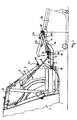
- Heckrod is one pivotable rear wall door 3 is provided, which is hinged to the collecting container and a bed 4 forms, in the large waste container 13 by lifting and overhead pivoting can be emptied by means of a Hubschwenkvorraum 5.
- FIG. 1 shows, at the rear below a loading edge 6, a pair are parallel, pivoted to the rear projecting lifting arms, namely pivotable about a common Hubarmachse 8, which extends transversely to the vehicle longitudinal axis horizontally, when the vehicle is on level ground.
- the lifting arms 7 are spaced from each other laterally arranged at the rear of the vehicle so that they can accommodate the refuse container 13 between them.
- a pair of hydraulic cylinders 9 are provided with their one End are hinged to one of the lifting arms 7, wherein according to the drawn Embodiment of the articulation point 10 approximately half the length of the lifting arms lies.
- the hydraulic cylinders 9 on side walls of the Bed 4 and the rear wall door 3 hinged.
- a pair of pivot arms 11 are articulated, which are like the Lifting arms 7 substantially parallel to the vertical vehicle longitudinal center plane extend.
- the pivot arms 11 are pivotally connected to the lifting arms 7, namely about a Hubarmachse 8 parallel, transverse to the vehicle longitudinal direction extending Schwenkarmachse 12.
- a Hubarmachse 8 parallel, transverse to the vehicle longitudinal direction extending Schwenkarmachse 12.
- the Schwenkarmachse 12 is located between the pivot point 10 of the hydraulic cylinder 9 and the cantilevered End of the lifting arm 7 in the projecting end half of the Lifting arm. In the illustrated embodiment, the Schwenkarmachse 12 is located approximately at two thirds of the length of the lifting arm 7.
- the lifting arm is the 7th approximately at the height of Schwenkarmachse 12 angled slightly upwards. While the hinged at the rear of the vehicle portion of the lifting arm 7 in the Receiving position extends approximately horizontally, the projecting end portion extends at an acute angle (see Figure 1).
- the pivot arms 11 are rearward beyond the lifting arms 7.
- the length the pivot arms 11 can be chosen differently, it corresponds at least the distance between the two lifting axes of the male container 13. In the drawn design corresponds to the length of the pivot arms 11 of the order of magnitude about the length of the lifting arms. 7
- the pivot arms 11 are in the lowered position down on the freely projecting ends of the lifting arms 7.
- the free end of the Lifting arms 7 form insofar pivot limit stops 14, d. H. beyond them the pivot arms 11 can not be pivoted.
- each two receiving jaws 15 and 16 are provided on the pivot arms 11 .
- a first receiving mouth 15 is at the freely projecting end of the swivel arm 11 provided while a second receiving mouth 16 approximately in the area of Schwenkarmachse 12 is provided on the pivot arm 11.
- the distance ofdusuler 15 and 16 corresponds to the distance of the lift bearings 17 and 18 of the male container 13, usually in the form of laterally projecting Hubzapfen or axes are formed.
- Figure 1 engages the outer Receiving mouth 15, the approximately centrally located lift bearing 17, while the inner Receiving mouth 16 which lies approximately at a front edge of the refuse container 13 Lifting bearing 18 engages.
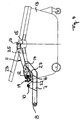
- the pivot arms 11 are formed as a rocker. They have operating sections 19, with respect to the Schwenkarmachse 12 compared to the essential longer, projecting backward actuating pieces 20 are, d. H. the Schwenkarmachse 12 is not located at one end of the pivot arms 11, but the Swivel arms 11 extend beyond the pivot axis also to the inner Page, d. H. towards the rear of the vehicle.
- the length of the operating portions 19 is only a fraction of the rearwardly projecting length of the pivot arms 11, so that a large leverage ratio is achieved, d. H. a little movement the operating portions 19 leads to a large pivoting backward cantilevered ends of the pivot arms 11.
- the length of the Operating portions 19 less than a quarter of the entire length of Swing arms 11.
- pivot arms 11 In addition, the pivotal movement of the pivot arms 11 forward relative to limited to the lifting arms 7.
- the ends of the pivot arms 14 on the side of the operating portions 19 are for this purpose on the lifting arms 7.
- the mentioned ends the pivot arms 11 and the associated portions of the lifting arms 7 form insofar Swivel limiter or pivot limiting stops 22 (see FIG. In the illustrated embodiment, the pivoting range of the pivot arms 11 limited to about 50 degrees relative to the lift arms 7.
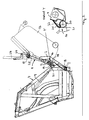
- Figure 3 is the Arrangement thereby essentially made such that in the upturned Position the Schwenkarmachse 12 is substantially at a height in the the initially vertically running from the bottom rear of the vehicle at an angle is beveled forward.
- the pivot arms 11 extend substantially parallel to the obliquely upward back contour of the bed. 4 (see Figure 3).
- the forced control device the pivotal movement of the pivot arms relative to the lift arms controls, consists of a trap-like catching device 26, connected to the Operating portions 19 of the pivot arms 14 is provided and the vehicle-fixed Stops against which the operating portions 19 of the pivot arms 11 be driven.
- a trap-like catching device 26 connected to the Operating portions 19 of the pivot arms 14 is provided and the vehicle-fixed Stops against which the operating portions 19 of the pivot arms 11 be driven.
- the Mouths 27 are positioned and aligned such that the actuating pieces 20 when raising the lifting arms in the mouths 27 retract. Are the lift arms off lowered the shown in Figure 3 fully raised position, prevent the Trap plates 25 that the pivot arms of the actuating pieces 20 solve.
- the pivot arms 11 are forced by the engagement between the catch plates 25 and the actuating pieces 20 turned back until the shown in Figure 2 Position is reached again, in which the pivot arms 11 back to the ends the lifting arms 7 rest.
- the mouths 27 are thus designed such that the Actuators 20 only in the back swung back position of Swing arms 11 are released. Through the described forced control is an uncontrolled repelling the pivot arms 11 completely prevented. They are gently swung back to their original position, where they continue Down swinging are held by gravity.
- a lid opener 24 is arranged on the pivot arms 11.
- Figure 3 shows the lid opener 24 pivotally cantilevered on Be stored at the end of the pivot arms 11.
- the lid opener 24 engages under the cover 23.
- the lid opener 24 is pivoted in opposite directions to the pivot arms 11, so that the lid 23 is opened.
- To drive the lid opener 24 can be provided a cable or a chain hoist, on the one hand below the Hubarmachse 8 is hinged to the rear of the vehicle and on the other hand at the top the pivot arms 7 is fixed and via a suitable coupling with the lid opener 24 is coupled.
Landscapes
- Engineering & Computer Science (AREA)
- Mechanical Engineering (AREA)
- Refuse-Collection Vehicles (AREA)
- Loading Or Unloading Of Vehicles (AREA)
- Orthopedics, Nursing, And Contraception (AREA)
- Harvester Elements (AREA)
- Cyclones (AREA)
- Refuse Receptacles (AREA)
Description
- Fig. 1:
- eine Seitenansicht des Hecks eines Müllsammelfahrzeugs mit einer heckseitigen Schüttung und einer Hubschwenkvorrichtung zum Anheben von Müllgroßbehältern, wobei die Hubschwenkvorrichtung in einer abgesenkten Grundstellung gezeigt ist, in der ein am Boden stehender Müllbehälter aufgenommen wird,
- Fig. 2:
- eine Seitenansicht des Fahrzeughecks ähnlich Figur 1, wobei die Hubschwenkvorrichtung den Müllbehälter bis in eine Stellung angehoben hat, in der ein Schwenkarmpaar der Hubschwenkvorrichtung anfängt, den Behälter relativ zu den Hubarmen der Hubschwenkvorrichtung noch weiter über Kopf zu kippen,
- Fig. 3:
- eine Seitenansicht des Fahrzeughecks ähnlich den vorhergehenden Figuren, wobei die Hubschwenkvorrichtung in ihre vollends nach oben geschwenkte Stellung gefahren und der Behälter in die Schüttung des Fahrzeugs ausgeschüttet wird, und
- Fig. 4:
- eine Seitenansicht der Hubarme und der Schwenkarme der Hubschwenkvorrichtung, die die Kinematik der beiden Armpaare zueinander verdeutlicht, wobei ein an den Schwenkarmen befestigter Deckelöffner der Übersichtlichkeit halber weggelassen wurde.
Claims (9)
- Schüttgutsammelfahrzeug mit einem Sammelbehälter (1), in den Behälter mit Schüttgut, insbesondere Müllgroßbehälter (13), ausschüttbar sind, sowie mit einer Hubvorrichtung (5) zum Anheben und Überkopfkippen der Behälter (13) in eine Beladeöffnung (2) des Sammelbehälters (1), wobei die Hubvorrichtung (5) ein Paar auskragende Hubarme (7) aufweist, die um eine Hubarmachse (8) schwenkbar gelagert sind, und an den Hubarmen (7) ein Paar auskragende Schwenkarme (11) um eine zur Hubarmachse (8) parallele Schwenkarmachse (12) schwenkbar gelagert sind, die jeweils ein Paar voneinander beabstandete Aufnahmen (15, 16) zur Aufnahme der Hublager (17, 18) des jeweils anzuhebenden Behälters (13) besitzen,
dadurch gekennzeichnet, dass die Schwenkarme (11) einen Betätigungsabschnitt (19) aufweisen, der mit einem chassis- bzw. sammelbehälterfesten Betätigungsstück (20) beim Anheben der Hubarme in Eingriff und beim Absenken der Hubarme außer Eingriff bringbar ist derart, dass die Schwenkarme (11) beim Anheben und Absenken der Hubarme (7) relativ zu diesen geschwenkt werden. - Schüttgutsammelfahrzeug nach dem vorhergehenden Anspruch, wobei die Schwenkarme (11) als Wippe ausgebildet sind, die einen Behältertragarmabschnitt (25) und einen bezüglich der Schwenkarmachse (12) gegenüberliegenden Betätigungsabschnitt (19) besitzt, mit dem die Wippe bei einem Hochschwenken der Hubarme (7) gegen ein Betätigungsstück (20), vorzugsweise in Form einer Rolle (21), fährt, derart, dass die Schwenkarme (11) relativ zu den Hubarmen schwenken.
- Schüttgutsammelfahrzeug nach einem der vorhergehenden Ansprüche, wobei die Schwenkarme (11) relativ zu den Hubarmen (7) einen begrenzten Schwenkbereich besitzen, vorzugsweise an den Schwenkarmen (11) und den Hubarmen (7) zusammenwirkende Schwenkbegrenzer (14, 22), insbesondere -anschläge, vorgesehen sind.
- Schüttgutsammelfahrzeug nach dem vorhergehenden Anspruch, wobei der Schwenkbereich weniger als 90 Grad, vorzugsweise weniger als 60 Grad beträgt.
- Schüttgutsammelfahrzeug nach einem der vorhergehenden Ansprüche, wobei die Schwenkarme (11) frei von einem eigenen Schwenkarmantrieb ausgebildet sind.
- Schüttgutsammelfahrzeug nach einem der vorhergehenden Ansprüche, wobei zwischen den Schwenkarmen (11) und den Hubarmen (7) ein Schwenkbewegungsdämpfer vorgesehen ist.
- Schüttgutsammelfahrzeug nach einem der vorhergehenden Ansprüche, wobei eine Zwangssteuerung (25, 20) für die Winkelstellung der Schwenkarme (11) relativ zu den Hubarmen (7) vorgesehen ist, die in einem oberen Schwenkbereich der Hubarme (7) die Schwenkarme (11) in Abhängigkeit der jeweiligen Hubarmstellung in vorgegebene Schwenkwinkelstellungen relativ zu den Hubarmen (7) zwingt.
- Schüttgutsammelfahrzeug nach einem der vorhergehenden Ansprüche, wobei an den Schwenkarmen (11) eine Fangvorrichtung (26) vorgesehen ist, die beim Anheben der Hubarme (7) ein chassis- bzw. sammelbehälterfestes Betätigungsstück (20) einfängt, mit dem Betätigungsstück (20) im oberen Schwenkbereich der Hubarme in Eingriff steht und von dem Betätigungsstück (20) beim Absenken der Hubarme (7) wieder außer Eingriff gerät.
- Schüttgutsammelfahrzeug nach einem der vorhergehenden Ansprüche, wobei an den Schwenkarmen (11) ein Deckelöffner (24) zum Öffnen eines Behälterdeckels (23) vorgesehen ist, vorzugsweise mit Antriebsmitteln gekoppelt ist, die den Deckelöffner (24) in Abhängigkeit einer Schwenkbewegung der Hubarme (7) betätigen.
Applications Claiming Priority (2)
| Application Number | Priority Date | Filing Date | Title |
|---|---|---|---|
| DE20119121U | 2001-11-23 | ||
| DE20119121U DE20119121U1 (de) | 2001-11-23 | 2001-11-23 | Schüttgutsammelfahrzeug |
Publications (2)
| Publication Number | Publication Date |
|---|---|
| EP1314657A1 EP1314657A1 (de) | 2003-05-28 |
| EP1314657B1 true EP1314657B1 (de) | 2005-02-02 |
Family
ID=7964384
Family Applications (1)
| Application Number | Title | Priority Date | Filing Date |
|---|---|---|---|
| EP02025126A Expired - Lifetime EP1314657B1 (de) | 2001-11-23 | 2002-11-08 | Schüttgutsammelfahrzeug |
Country Status (4)
| Country | Link |
|---|---|
| EP (1) | EP1314657B1 (de) |
| AT (1) | ATE288394T1 (de) |
| DE (2) | DE20119121U1 (de) |
| ES (1) | ES2236426T3 (de) |
Families Citing this family (2)
| Publication number | Priority date | Publication date | Assignee | Title |
|---|---|---|---|---|
| CN102942000B (zh) * | 2012-10-19 | 2015-05-27 | 江苏悦达专用车有限公司 | 后装压缩式垃圾车翻桶装置 |
| CN105329594B (zh) * | 2015-11-30 | 2018-06-29 | 江苏悦达专用车有限公司 | 一种后装式垃圾车 |
Family Cites Families (9)
| Publication number | Priority date | Publication date | Assignee | Title |
|---|---|---|---|---|
| GB723223A (en) * | 1953-01-05 | 1955-02-02 | Eagle Eng Co Ltd | Improvements connected with refuse collecting vehicles |
| DE2101015C3 (de) * | 1971-01-11 | 1980-11-06 | Zoeller-Kipper Gmbh, 6500 Mainz | Vorrichtung zum Entleeren von Behältern, beispielsweise MüUgefäflen |
| DE2524159C3 (de) * | 1975-05-31 | 1981-10-29 | Zöller-Kipper GmbH, 6500 Mainz | Vorrichtung zum Entleeren von mit seitlich vorstehenden Tragelementen, beispielsweise Tragzapfen, versehenen Behältern |
| NL7705096A (nl) * | 1977-05-09 | 1978-11-13 | Geesink Bv | Huisvuil-verzamelwagen met belading. |
| DE8811472U1 (de) * | 1988-09-10 | 1988-10-27 | Alustahl Behälterbau GmbH & Co KG, 28816 Stuhr | Lkw-Kastenaufbau mit einer Müllbehälter-Umladevorrichtung |
| IT1270139B (it) * | 1994-05-26 | 1997-04-29 | Ecology System International S | Dispositivo per l'aggancio,il sollevamento e lo scarico di cassonetti per la raccolta di rifiuti per autocarro a caricamento laterale |
| DE29601315U1 (de) * | 1996-01-26 | 1996-04-04 | Hüffermann Entsorgungssysteme GmbH, 27793 Wildeshausen | Vorrichtung zum Entleeren von Großbehältern nach einem Umleerprinzip |
| DE19655095C2 (de) * | 1996-01-29 | 2002-03-07 | Faun Umwelttechnik Gmbh & Co | Müllsammelfahrzeug mit zwei um eine Querachse schwenkbar am Fahrgestell gelagerten Bügeln einer Hub-Kipp-Vorrichtung |
| NL1004252C1 (nl) * | 1996-10-11 | 1998-04-15 | Geesink Bv | Inrichting voor het in een verzamelreservoir legen van vuilnishouders. |
-
2001
- 2001-11-23 DE DE20119121U patent/DE20119121U1/de not_active Expired - Lifetime
-
2002
- 2002-11-08 AT AT02025126T patent/ATE288394T1/de active
- 2002-11-08 EP EP02025126A patent/EP1314657B1/de not_active Expired - Lifetime
- 2002-11-08 ES ES02025126T patent/ES2236426T3/es not_active Expired - Lifetime
- 2002-11-08 DE DE50202164T patent/DE50202164D1/de not_active Expired - Lifetime
Also Published As
| Publication number | Publication date |
|---|---|
| ATE288394T1 (de) | 2005-02-15 |
| DE50202164D1 (de) | 2005-03-10 |
| EP1314657A1 (de) | 2003-05-28 |
| ES2236426T3 (es) | 2005-07-16 |
| DE20119121U1 (de) | 2003-04-03 |
Similar Documents
| Publication | Publication Date | Title |
|---|---|---|
| DE69618789T2 (de) | Schwenkbare vorrichtung zum greifen,heben und kippen von behältern | |
| EP0235784B1 (de) | Kippvorrichtung für motorgetriebene Müllsammelfahrzeuge | |
| EP0364835B1 (de) | Müllsammelfahrzeug | |
| DE3888077T2 (de) | Greif-, Hub- und Kippvorrichtung zum Entleeren von Müllbehältern, wobei die Vorrichtung an der Seite eines Müllfahrzeuges angebracht ist. | |
| DE2407615A1 (de) | Muell-sammelfahrzeug | |
| DE3313282C2 (de) | Hub- und Kippvorrichtung zum Entleeren von größeren Müllgefäßen | |
| EP0720957A1 (de) | Fahrzeug zum Aufnehmen und Transportieren von Abfallstoffen mit einem Träger für die Aufnahmevorrichtung | |
| DE2654542B2 (de) | Hub-Kipp-Vorrichtung für Behälter, insbesondere zum Entleeren von Müllgefäßen in Müllsammelbehälter. | |
| DE1226035B (de) | Fahrzeug mit vorderseitig angeordneter Beladevorrichtung, insbesondere zum Entleeren von Muellsammelbehaeltern in den Wagenaufbau | |
| EP1314657B1 (de) | Schüttgutsammelfahrzeug | |
| DE3720442C2 (de) | ||
| DE9418696U1 (de) | Vorrichtung zum Anheben und Entleeren von Recyclingbehältern | |
| CH630033A5 (de) | Hub-kippvorrichtung zum entleeren von behaeltern in sammelbehaelter, insbesondere von muellbehaeltern in muellsammelfahrzeuge. | |
| DE2909438A1 (de) | Kippvorrichtung fuer behaelter, insbesondere muellbehaelter | |
| DE3830989A1 (de) | Hubkippvorrichtung zum entleeren von muellbehaeltern in ein sammelfahrzeug | |
| DD296658A5 (de) | Muellsammelfahrzeug | |
| DE2730507A1 (de) | Beladevorrichtung fuer muellfahrzeuge | |
| DE1245840B (de) | Kippvorrichtung zum Entleeren von Grossraum-Muellbehaeltern in eine Einschuett-vorrichtung an Muellwagen | |
| DE2741448A1 (de) | Sammelbehaelter fuer muell | |
| EP0837791A1 (de) | Einrichtung an einem fahrzeug zum aufnehmen und absetzen von wechselaufbauten | |
| EP0763488B1 (de) | Müllsammelfahrzeug | |
| DE4334602C1 (de) | Trittbrett für ein Müllsammelfahrzeug | |
| DE935118C (de) | Selbsttaetige Ladevorrichtung fuer Muellwagen | |
| DE3809134A1 (de) | Vorrichtung zum entleeren von behaeltern | |
| DE19516133B4 (de) | Vorrichtung zum Entleeren von Müllgroßbehältern |
Legal Events
| Date | Code | Title | Description |
|---|---|---|---|
| PUAI | Public reference made under article 153(3) epc to a published international application that has entered the european phase |
Free format text: ORIGINAL CODE: 0009012 |
|
| 17P | Request for examination filed |
Effective date: 20021120 |
|
| AK | Designated contracting states |
Designated state(s): AT BE BG CH CY CZ DE DK EE ES FI FR GB GR IE IT LI LU MC NL PT SE SK TR |
|
| AX | Request for extension of the european patent |
Extension state: AL LT LV MK RO SI |
|
| 17Q | First examination report despatched |
Effective date: 20031203 |
|
| AKX | Designation fees paid |
Designated state(s): AT BE BG CH CY CZ DE DK EE ES FI FR GB GR IE IT LI LU MC NL PT SE SK TR |
|
| GRAP | Despatch of communication of intention to grant a patent |
Free format text: ORIGINAL CODE: EPIDOSNIGR1 |
|
| GRAS | Grant fee paid |
Free format text: ORIGINAL CODE: EPIDOSNIGR3 |
|
| GRAA | (expected) grant |
Free format text: ORIGINAL CODE: 0009210 |
|
| AK | Designated contracting states |
Kind code of ref document: B1 Designated state(s): AT BE BG CH CY CZ DE DK EE ES FI FR GB GR IE IT LI LU MC NL PT SE SK TR |
|
| PG25 | Lapsed in a contracting state [announced via postgrant information from national office to epo] |
Ref country code: SK Free format text: LAPSE BECAUSE OF FAILURE TO SUBMIT A TRANSLATION OF THE DESCRIPTION OR TO PAY THE FEE WITHIN THE PRESCRIBED TIME-LIMIT Effective date: 20050202 Ref country code: IE Free format text: LAPSE BECAUSE OF FAILURE TO SUBMIT A TRANSLATION OF THE DESCRIPTION OR TO PAY THE FEE WITHIN THE PRESCRIBED TIME-LIMIT Effective date: 20050202 Ref country code: BG Free format text: LAPSE BECAUSE OF FAILURE TO SUBMIT A TRANSLATION OF THE DESCRIPTION OR TO PAY THE FEE WITHIN THE PRESCRIBED TIME-LIMIT Effective date: 20050202 Ref country code: CZ Free format text: LAPSE BECAUSE OF FAILURE TO SUBMIT A TRANSLATION OF THE DESCRIPTION OR TO PAY THE FEE WITHIN THE PRESCRIBED TIME-LIMIT Effective date: 20050202 Ref country code: TR Free format text: LAPSE BECAUSE OF FAILURE TO SUBMIT A TRANSLATION OF THE DESCRIPTION OR TO PAY THE FEE WITHIN THE PRESCRIBED TIME-LIMIT Effective date: 20050202 Ref country code: FI Free format text: LAPSE BECAUSE OF FAILURE TO SUBMIT A TRANSLATION OF THE DESCRIPTION OR TO PAY THE FEE WITHIN THE PRESCRIBED TIME-LIMIT Effective date: 20050202 Ref country code: EE Free format text: LAPSE BECAUSE OF FAILURE TO SUBMIT A TRANSLATION OF THE DESCRIPTION OR TO PAY THE FEE WITHIN THE PRESCRIBED TIME-LIMIT Effective date: 20050202 |
|
| REG | Reference to a national code |
Ref country code: GB Ref legal event code: FG4D Free format text: NOT ENGLISH |
|
| REG | Reference to a national code |
Ref country code: CH Ref legal event code: EP Ref country code: CH Ref legal event code: NV Representative=s name: BOVARD AG PATENTANWAELTE |
|
| REG | Reference to a national code |
Ref country code: IE Ref legal event code: FG4D Free format text: GERMAN |
|
| REF | Corresponds to: |
Ref document number: 50202164 Country of ref document: DE Date of ref document: 20050310 Kind code of ref document: P |
|
| PG25 | Lapsed in a contracting state [announced via postgrant information from national office to epo] |
Ref country code: SE Free format text: LAPSE BECAUSE OF FAILURE TO SUBMIT A TRANSLATION OF THE DESCRIPTION OR TO PAY THE FEE WITHIN THE PRESCRIBED TIME-LIMIT Effective date: 20050502 Ref country code: DK Free format text: LAPSE BECAUSE OF FAILURE TO SUBMIT A TRANSLATION OF THE DESCRIPTION OR TO PAY THE FEE WITHIN THE PRESCRIBED TIME-LIMIT Effective date: 20050502 Ref country code: GR Free format text: LAPSE BECAUSE OF FAILURE TO SUBMIT A TRANSLATION OF THE DESCRIPTION OR TO PAY THE FEE WITHIN THE PRESCRIBED TIME-LIMIT Effective date: 20050502 |
|
| GBT | Gb: translation of ep patent filed (gb section 77(6)(a)/1977) |
Effective date: 20050428 |
|
| REG | Reference to a national code |
Ref country code: ES Ref legal event code: FG2A Ref document number: 2236426 Country of ref document: ES Kind code of ref document: T3 |
|
| REG | Reference to a national code |
Ref country code: IE Ref legal event code: FD4D |
|
| PG25 | Lapsed in a contracting state [announced via postgrant information from national office to epo] |
Ref country code: CY Free format text: LAPSE BECAUSE OF FAILURE TO SUBMIT A TRANSLATION OF THE DESCRIPTION OR TO PAY THE FEE WITHIN THE PRESCRIBED TIME-LIMIT Effective date: 20051108 |
|
| PG25 | Lapsed in a contracting state [announced via postgrant information from national office to epo] |
Ref country code: LU Free format text: LAPSE BECAUSE OF NON-PAYMENT OF DUE FEES Effective date: 20051130 Ref country code: MC Free format text: LAPSE BECAUSE OF NON-PAYMENT OF DUE FEES Effective date: 20051130 |
|
| PLBE | No opposition filed within time limit |
Free format text: ORIGINAL CODE: 0009261 |
|
| STAA | Information on the status of an ep patent application or granted ep patent |
Free format text: STATUS: NO OPPOSITION FILED WITHIN TIME LIMIT |
|
| ET | Fr: translation filed | ||
| 26N | No opposition filed |
Effective date: 20051103 |
|
| BECA | Be: change of holder's address |
Owner name: *Z?LLER-KIPPER G.M.B.H.HANS-Z?LLER-STRASSE 50-68, Effective date: 20050202 |
|
| BECH | Be: change of holder |
Owner name: *Z?LLER-KIPPER G.M.B.H. Effective date: 20050202 |
|
| PG25 | Lapsed in a contracting state [announced via postgrant information from national office to epo] |
Ref country code: PT Free format text: LAPSE BECAUSE OF NON-PAYMENT OF DUE FEES Effective date: 20050702 |
|
| REG | Reference to a national code |
Ref country code: CH Ref legal event code: PUE Owner name: ZOELLER-KIPPER GMBH Free format text: FAUN UMWELTTECHNIK GMBH & CO.#AM MITTLEREN MOOS 59#86167 AUGSBURG (DE) -TRANSFER TO- ZOELLER-KIPPER GMBH#HANS-ZOELLER-STRASSE 50-68#55130 MAINZ (DE) |
|
| REG | Reference to a national code |
Ref country code: GB Ref legal event code: 732E |
|
| NLS | Nl: assignments of ep-patents |
Owner name: ZOELLER-KIPPER GMBH Effective date: 20080310 |
|
| REG | Reference to a national code |
Ref country code: FR Ref legal event code: TP |
|
| REG | Reference to a national code |
Ref country code: ES Ref legal event code: PC2A |
|
| REG | Reference to a national code |
Ref country code: CH Ref legal event code: PFA Owner name: ZOELLER-KIPPER GMBH Free format text: ZOELLER-KIPPER GMBH#HANS-ZOELLER-STRASSE 50-68#55130 MAINZ (DE) -TRANSFER TO- ZOELLER-KIPPER GMBH#HANS-ZOELLER-STRASSE 50-68#55130 MAINZ (DE) |
|
| REG | Reference to a national code |
Ref country code: FR Ref legal event code: PLFP Year of fee payment: 14 |
|
| REG | Reference to a national code |
Ref country code: FR Ref legal event code: PLFP Year of fee payment: 15 |
|
| REG | Reference to a national code |
Ref country code: FR Ref legal event code: PLFP Year of fee payment: 16 |
|
| PGFP | Annual fee paid to national office [announced via postgrant information from national office to epo] |
Ref country code: DE Payment date: 20191125 Year of fee payment: 18 Ref country code: NL Payment date: 20191121 Year of fee payment: 18 |
|
| PGFP | Annual fee paid to national office [announced via postgrant information from national office to epo] |
Ref country code: BE Payment date: 20191121 Year of fee payment: 18 Ref country code: FR Payment date: 20191121 Year of fee payment: 18 Ref country code: ES Payment date: 20191216 Year of fee payment: 18 Ref country code: IT Payment date: 20191120 Year of fee payment: 18 |
|
| PGFP | Annual fee paid to national office [announced via postgrant information from national office to epo] |
Ref country code: AT Payment date: 20191119 Year of fee payment: 18 Ref country code: CH Payment date: 20191125 Year of fee payment: 18 |
|
| PGFP | Annual fee paid to national office [announced via postgrant information from national office to epo] |
Ref country code: GB Payment date: 20191126 Year of fee payment: 18 |
|
| REG | Reference to a national code |
Ref country code: DE Ref legal event code: R119 Ref document number: 50202164 Country of ref document: DE |
|
| REG | Reference to a national code |
Ref country code: CH Ref legal event code: PL |
|
| REG | Reference to a national code |
Ref country code: NL Ref legal event code: MM Effective date: 20201201 |
|
| REG | Reference to a national code |
Ref country code: AT Ref legal event code: MM01 Ref document number: 288394 Country of ref document: AT Kind code of ref document: T Effective date: 20201108 |
|
| GBPC | Gb: european patent ceased through non-payment of renewal fee |
Effective date: 20201108 |
|
| REG | Reference to a national code |
Ref country code: BE Ref legal event code: MM Effective date: 20201130 |
|
| PG25 | Lapsed in a contracting state [announced via postgrant information from national office to epo] |
Ref country code: CH Free format text: LAPSE BECAUSE OF NON-PAYMENT OF DUE FEES Effective date: 20201130 Ref country code: AT Free format text: LAPSE BECAUSE OF NON-PAYMENT OF DUE FEES Effective date: 20201108 Ref country code: NL Free format text: LAPSE BECAUSE OF NON-PAYMENT OF DUE FEES Effective date: 20201201 Ref country code: LI Free format text: LAPSE BECAUSE OF NON-PAYMENT OF DUE FEES Effective date: 20201130 |
|
| PG25 | Lapsed in a contracting state [announced via postgrant information from national office to epo] |
Ref country code: FR Free format text: LAPSE BECAUSE OF NON-PAYMENT OF DUE FEES Effective date: 20201130 Ref country code: IT Free format text: LAPSE BECAUSE OF NON-PAYMENT OF DUE FEES Effective date: 20201108 |
|
| PG25 | Lapsed in a contracting state [announced via postgrant information from national office to epo] |
Ref country code: DE Free format text: LAPSE BECAUSE OF NON-PAYMENT OF DUE FEES Effective date: 20210601 Ref country code: GB Free format text: LAPSE BECAUSE OF NON-PAYMENT OF DUE FEES Effective date: 20201108 |
|
| REG | Reference to a national code |
Ref country code: ES Ref legal event code: FD2A Effective date: 20220202 |
|
| PG25 | Lapsed in a contracting state [announced via postgrant information from national office to epo] |
Ref country code: ES Free format text: LAPSE BECAUSE OF NON-PAYMENT OF DUE FEES Effective date: 20201109 |
|
| PG25 | Lapsed in a contracting state [announced via postgrant information from national office to epo] |
Ref country code: BE Free format text: LAPSE BECAUSE OF NON-PAYMENT OF DUE FEES Effective date: 20201130 |