EP1308276A1 - Einrichtung zum Behandeln beidseitig bedruckter und/oder lackierter Bogen - Google Patents
Einrichtung zum Behandeln beidseitig bedruckter und/oder lackierter Bogen Download PDFInfo
- Publication number
- EP1308276A1 EP1308276A1 EP02023700A EP02023700A EP1308276A1 EP 1308276 A1 EP1308276 A1 EP 1308276A1 EP 02023700 A EP02023700 A EP 02023700A EP 02023700 A EP02023700 A EP 02023700A EP 1308276 A1 EP1308276 A1 EP 1308276A1
- Authority
- EP
- European Patent Office
- Prior art keywords
- sheet
- air
- chain
- powder
- dryer
- Prior art date
- Legal status (The legal status is an assumption and is not a legal conclusion. Google has not performed a legal analysis and makes no representation as to the accuracy of the status listed.)
- Granted
Links
- 239000004753 textile Substances 0.000 claims abstract description 18
- 239000000843 powder Substances 0.000 claims description 15
- 238000007664 blowing Methods 0.000 claims description 13
- 239000000203 mixture Substances 0.000 claims description 3
- 238000001035 drying Methods 0.000 abstract description 5
- 238000000227 grinding Methods 0.000 description 3
- 239000004744 fabric Substances 0.000 description 1
- 238000005461 lubrication Methods 0.000 description 1
- 239000000463 material Substances 0.000 description 1
- 230000005855 radiation Effects 0.000 description 1
- 239000000758 substrate Substances 0.000 description 1
- 238000011144 upstream manufacturing Methods 0.000 description 1
Images


Classifications
-
- B—PERFORMING OPERATIONS; TRANSPORTING
- B41—PRINTING; LINING MACHINES; TYPEWRITERS; STAMPS
- B41F—PRINTING MACHINES OR PRESSES
- B41F23/00—Devices for treating the surfaces of sheets, webs, or other articles in connection with printing
- B41F23/04—Devices for treating the surfaces of sheets, webs, or other articles in connection with printing by heat drying, by cooling, by applying powders
- B41F23/044—Drying sheets, e.g. between two printing stations
- B41F23/0443—Drying sheets, e.g. between two printing stations after printing
Definitions
- the invention relates to a device for treating sheets printed and / or varnished on both sides in printing presses, the sheets transported along a sheet conveying path by the gripper carriage being supported in their conveyance by a sheet guiding device arranged below the sheet conveying path and drying and / or powdering devices being provided above the sheet conveying path. which correspond to a sheet guiding device arranged below the sheet conveying path.
- Hot air dryers are used in printing machines to dry painted sheets.
- the air jet influences the bow. Due to the air jet, the arc forms a wave that penetrates the air cushion that has formed between the sheet guiding device and the arc. The result is that the sheet touches and lubricates the sheet guiding device. This effect also occurs when the bow is powdered and the powder jet hits the bow.
- the dryer is a combination dryer with IR radiation and hot air working, provided. Below the sheet conveyor path, the combination dryer opposite, a sheet guide device is provided, which is lowered in the middle and can be supplied with suction and blowing air.
- the sheet guide device is said to be a non-contact Ensure guiding of the printed sheets, especially for sheets printed on both sides. If the sheet comes into contact with the sheet guide device lubricates the bow off.
- Sheet guiding devices in printing machines are also known which are arranged below the sheet guiding path and are intended to enable sheet guiding without lubrication.
- the sheet guiding device consists of endless revolving support bands, which are guided over two spaced shafts. This document does not refer to the sheet guiding device relating to a dryer or a powder device (DE 40 30 374 A1).
- the object of the invention is to provide a printed and / or varnished in the printing press Sheet in sheet delivery with a blowing air jet acting on the sheet from above treat without the sheet smearing.
- the invention surprisingly ensures drying and powdering of one sheets printed on both sides in the sheet delivery without greasing. allows this is achieved by assigning a rotating sheet guiding device to one Combination dryer and / or a powder device.
- the speed of the revolving Sheet guiding device which has a textile fabric, is the machine speed, with which the sheet rotates in the sheet delivery. Blowing or suction air acting from the air box against the arch from below, support the arch guidance.
- Fig. 1 shows a schematic representation of a complete sheet delivery 1 to illustrate the location of the invention in the machine.
- a pressure cylinder 28 is arranged upstream of the sheet delivery 1.
- the front and rear chain deflection wheel 2, 3 are shown, via which the endless chain circle 4 with the gripper carriage 5 is guided.
- the gripper carriages 5 convey the printing material (sheet) 6 via the delivery stack 7.
- From the delivery arm 1, the front sheet stops 9 and the suction roller 8 are also shown.
- Air generators 27 are arranged above and in front of the boom stack 7.
- the sheet delivery also has a non-stop device 11 for changing the stack.
- An air box 13, which is assigned to the front chain deflection wheel 2 and an air guide plate 14 with openings 25 which can be acted upon pneumatically, is arranged below the sheet conveying path 12.
- a combination dryer 15 and below that a sheet guiding device 16 corresponding to the combination dryer is provided within the chain circle 4 (FIG. 2).
- the combination dryer 15 and the sheet guiding device 16 can also be used in a sheet delivery 1 with a delivery extension. You just have to correspond to each other.
- a powder device 29 can also be provided.
- combination dryer 15 and powder device 29 are shown as a box to clarify the location. 2 shows the combination dryer 15 and the sheet guiding device 16 in a detailed representation.
- the combination dryer 15 consists of a warm air squeegee 17, an infrared dryer 18 and a cold air squeegee 19, seen in the direction of travel of the sheet.
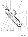
- the equipment of the combination dryer 15 can also be different from that shown in the exemplary embodiment. It would also be conceivable to design the combination dryer 15 as an infrared dryer 18 with a downstream cold air doctor blade 19. 3 shows a powder device 29 arranged above the sheet conveying path 12, to which the sheet guiding device 16 is again assigned. It can be seen that both the combination dryer 15 and the powder device 28 act on the sheet 6 through a blow jet 20.
- the blow jet 20 consists of warm air or cold air.
- the blow jet 20 consists of a powder-air mixture.
- Combination dryer 15 and powder device can be provided individually as shown in FIGS. 2 and 3 or together in a sheet delivery 1.
- the sheet guide device 16 has the following structure.
- a chain 22 is guided on both sides via two chain wheels 21.
- the sprockets 21 are spaced from each other and a sprocket 21 is provided with a drive.
- the drive is designed in such a way that the sheet guiding device 16 runs at the same speed as the machine speed in the sheet conveying direction.
- Two diametrically opposed tensioning shafts 24 are arranged on the chain 22.
- a textile belt 23 extending across the width of the sheet conveying path 12 is fastened to the tensioning shafts 24 between the chains 21.
- the textile belt 23 is permeable to air and it is moved quasi like a conveyor belt around the chain wheels 21 and it runs on an air box 26 which has a closed surface which has openings 25 directed towards the arch 6.
- Air generators 27 are provided within the air box 26. However, it is also possible to apply air to the air box 26 from the outside via air lines. The surface of the air box 26 forms a guide surface for the textile belt 23. The air generators 27 can optionally be acted upon by suction or blown air depending on the pressure application.
- the printed and / or varnished sheet 6 is taken over by the grippers 5 of the chain circle 4 by the printing cylinder 28, dried and / or varnished in the sheet delivery 1 and deposited on the delivery stack 7.
- the sheet 6 is acted upon by the blowing jet 20 of the warm air doctor blade 17 and then by the blowing jet 20 of the cold air doctor blade 19.
- the sheet 6 is dried by the infrared dryer 18 between the exposure to warm air and cold air.
- the sheet 6 is acted upon by the blowing jet 20 consisting of a powder / air mixture.
- the sheet 6 can be supplied with blown air or with suction air via the openings 25.
- a supporting air cushion acting against the blowing jet 20 is generated on the sheet 6.
- the air box 26 is subjected to suction air, a non-positive connection is established between the arch 6 and the textile belt 23, which counteracts a possible relative movement between the arch 6 and the textile belt 23.
- the guide surface of the air box 26 ensures that the textile band 23 slides securely on the air box 26.
Landscapes
- Engineering & Computer Science (AREA)
- Mechanical Engineering (AREA)
- Treatment Of Fiber Materials (AREA)
- Drying Of Solid Materials (AREA)
Abstract
Description
Zur Trocknung von lackierten Bogen setzt man in Druckmaschinen Heißlufttrockner ein. Dabei beeinflusst der Luftstrahl den Bogen. Durch den Luftstrahl bildet der Bogen eine Welle die das Luftpolster durchschlägt, das sich zwischen Bogenleiteinrichtung und Bogen ausgebildet hat. Die Folge ist, dass der Bogen die Bogenleiteinrichtung berührt und abschmiert. Dieser Effekt tritt auch auf, wenn der Bogen gepudert wird und der Puderstrahl auf den Bogen trifft.
Ein Bezug der Bogenführeinrichtung zu einem Trockner oder einer Pudereinrichtung ist ist dieser Schrift nicht entnehmbar (DE 40 30 374 A1).
- Fig. 1
- schematische Darstellung eines Bogenauslegers zur Darstellung der Wirkungsortes der Erfindung
- Fig. 2
- Trockner mit einer Bogenführungseinrichtung in detaillierter Darstellung.
- Fig. 3
- Pudereinrichtung mit einer Bogenführungseinrichtung
Innerhalb des Kettenkreises 4 ist ein Kombinationstrockner 15 und darunter eine mit dem Kombinationstrockner korrespondierende Bogenführungseinrichtung 16 vorgesehen (Fig. 2). Der Kombinationstrockner 15 und die Bogenführungseinrichtung 16 können auch in einem Bogenausleger 1 mit Auslageverlängerung eingesetzt werden. Sie müssen nur zueinander korrespondieren.
Anstelle des Kombinationstrockners 15 oder gemeinsam mit diesem kann auch eine Pudereinrichtung 29 vorgesehen sein.
In Fig. 1 sind Kombinationstrockner 15 und Pudereinrichtung 29 zur Verdeutlichung des Standortes als Kasten eingezeichnet.
Fig. 2 zeigt den Kombinationstrockner 15 und die Bogenführungseinrichtung 16 in detaillierter Darstellung. Der Kombinationstrockner 15 besteht in Bogenlaufrichtung gesehen aus einer Warmluftrakel 17, einem Infrarottrockner 18 und einer Kaltluftrakel 19. Die Blasstrahlen 20 von Warm- und Kaltluftrakel 17,19 sind auf den Bogen 6 gerichtet.
Die Ausstattung des Kombinationstrockners 15 kann auch eine andere sein als im Ausführungsbeispiel dargestellt. Denkbar wäre auch, den Kombinationstrockner 15 als Infrarottrockner 18 mit einer nachgeschalteten Kaltluftrakel 19 auszugestalten.
Fig. 3 zeigt eine oberhalb des Bogenförderweges 12 angeordnete Pudereinrichtung 29, der wieder die Bogenführungseinrichtung 16 zugeordnet ist. Es ist erkennbar, dass sowohl der Kombinationstrockner 15 als auch die Pudereinrichtung 28 durch einen Blasstrahl 20 auf den Bogen 6 wirken. Beim Kombinationstrockner 15 besteht der Blasstrahl 20 aus Warmluft oder Kaltluft Beim Einsatz einer Pudereinrichtung 29 besteht der Blasstrahl 20 aus einem Puder - Luftgemisch.
Kombinationstrockner 15 und Pudereinrichtung können einzeln wie in Fig 2 und 3 dargestellt oder gemeinsam in einem Bogenausleger 1 vorgesehen werden.
Die Lufterzeuger 27 können wahlweise in Abhängigkeit vom Druckauftrag mit Saug- oder Blasluft beaufschlagt werden.
Beim Passieren des Kombinationstrockners 15 wird der Bogen 6 mit dem Blasstrahl 20 der Warmluftrakel 17 und danach mit dem Blasstrahl 20 der Kaltluftrakel 19 beaufschlagt. Zwischen der Beaufschlagung mittels Warmluft und Kaltluft wird der Bogen 6 durch den Infrarottrockner 18 getrocknet.
Bei Einsatz einer Pudereinrichtung 29 wird der Bogen 6 durch den aus einem Puder - Luftgemisch bestehenden Blasstrahl 20 beaufschlagt.
Durch die Beaufschlagung des Bogens 6 von oben mittels Blasstrahl 20 wird dieser auf das Textilband 23 gedrückt. Da das Textilband 23 mit Maschinengeschwindigkeit umläuft, entsteht keine Relativbewegung zwischen Bogen 6 und Textilband 23. Geringfügige Geschwindigkeitsdifferenzen zwischen Bogen 6 und Textilband 23 werden durch das Textilband 23, das in begrenztem Maß der Bewegung des Bogens 6 folgen kann, ausgeglichen.
Bei Beaufschlagung des Luftkastens 26 mit Saugluft wird eine kraftschlüssige Verbindung zwischen Bogen 6 und Textilband 23 aufgebaut, die einer eventuellen Relativbewegung zwischen Bogen 6 und Textilband 23 entgegenwirkt.
Darüber hinaus gewährleistet die Leitfläche des Luftkastens 26 ein sicheres Gleiten des Textilbandes 23 auf dem Luftkasten 26.
- 1
- Bogenausleger
- 2
- vorderes Kettenumlenkrad
- 3
- hinteres Kettenumlenkrad
- 4
- Kettenkreis
- 5
- Greiferwagen
- 6
- Bedruckstoff, Bogen
- 7
- Auslegerstapel
- 8
- Saugwalze
- 9
- Vordere Bogenanschläge
- 10 11
- Non-Stop-Einrichtung
- 12
- Bogenförderweg
- 13
- Luftkasten
- 14
- Luftleitblech
- 15
- Kombinationstrockner
- 16
- Bogenführungseinrichtung
- 17
- Warmluftrakel
- 18
- Infrarottrockner
- 19
- Kaltluftrakel
- 20
- Blasstrahl
- 21
- Kettenrad
- 22
- Kette
- 23
- Textilband
- 24
- Spannwelle
- 25
- Öffnungen
- 26
- Luftkasten
- 27
- Lufterzeuger
- 28
- Druckzylinder
- 29
- Pudereinrichtung
Claims (14)
- Einrichtung zum Behandeln von beidseitig bedruckter und/oder lackierter Bogen (6) in Bogenauslegern (1) von Druckmaschinen, in denen der Bogen (6) längs eines Bogenförderweges (12) von am umlaufenden Kettenkreis (4) angeordneten Greiferwagen (5) gefördert und auf dem Auslegerstapel (7) abgelegt wird und auf dem Weg zum Auslegerstapel (7) ein mit einen Blasstrahl (20) von oben auf den Bogen (6) einwirkender Kombinationstrockner (15) und /oder eine Pudereinrichtung (29) vorgesehen sind und dem Kombinationstrockner (15) und/oder der Pudereinrichtung (29) eine unterhalb des Bogenförderweges (29) angeordnete Bogenführungseinrichtung (16), bestehend aus einem umlaufenden, den Bogen (6) stützenden endlosen Textilband (23), zugeordnet sind.
- Einrichtung nach Anspruch 1, wobei das an Spanwellen (24) angeordnete Textilband (23) und eine mit den Spanwellen (24) verbundene Kette (22) über zwei zueinander beabstandete Kettenräder (21) geführt werden.
- Einrichtung nach Anspruch 2, wobei innerhalb der Kette (22) ein Luftkasten (26) angeordnet ist.
- Einrichtung nach Anspruch 2, wobei das Textilband (23) sich über die Breite des Bogenförderweges (12) erstreckt.
- Einrichtung nach Anspruch 2, wobei an der Kette (22) zwei sich diametral gegenüberliegende Spannwellen (24) angeordnet sind.
- Einrichtung nach Anspruch 1, wobei das Textilband (23) luftdurchlässig ist.
- Einrichtung nach Anspruch 3, wobei der Luftkasten (26) zum Bogen (6) gerichtete Öffnungen (25) aufweist.
- Einrichtung nach Anspruch 3, wobei im Luftkasten (26) mindestens ein Lufterzeuger (27) vorgesehen ist.
- Einrichtung nach Anspruch 3, wobei der Luftkasten (26) mit Saug- oder Blasluft beaufschlagbar ist.
- Einrichtung nach Anspruch 1, wobei die Kettenräder (21) mit Maschinengeschwindigkeit antreibbar sind.
- Einrichtung nach Anspruch 1, wobei der Kombinationstrockner (16) aus mindestens einer Warm- und einer Kaltluftrakel (17,19) gebildet wird.
- Einrichtung nach Anspruch 11, wobei zwischen der Warm- und Kaltluftrakel (17,19) ein Infrarottrockner (18) angeordnet ist.
- Einrichtung nach Anspruch 1, wobei der Blasstrahl (20) der Pudereinrichtung (29) aus einem Puder-Luft-Gemisch besteht.
- Einrichtung nach Anspruch 3, wobei die Oberfläche des Luftkastens (26) als Leitfläche für das Textilband (23) ausgebildet ist.
Applications Claiming Priority (2)
| Application Number | Priority Date | Filing Date | Title |
|---|---|---|---|
| DE10154416 | 2001-11-06 | ||
| DE2001154416 DE10154416B4 (de) | 2001-11-06 | 2001-11-06 | Einrichtung zum Behandeln beidseitig bedruckter und/oder lackierter Bogen |
Publications (3)
| Publication Number | Publication Date |
|---|---|
| EP1308276A1 true EP1308276A1 (de) | 2003-05-07 |
| EP1308276B1 EP1308276B1 (de) | 2006-06-14 |
| EP1308276B2 EP1308276B2 (de) | 2013-01-02 |
Family
ID=7704749
Family Applications (1)
| Application Number | Title | Priority Date | Filing Date |
|---|---|---|---|
| EP02023700A Expired - Lifetime EP1308276B2 (de) | 2001-11-06 | 2002-10-23 | Einrichtung zum Behandeln beidseitig bedruckter und/oder lackierter Bogen |
Country Status (2)
| Country | Link |
|---|---|
| EP (1) | EP1308276B2 (de) |
| DE (2) | DE10154416B4 (de) |
Families Citing this family (3)
| Publication number | Priority date | Publication date | Assignee | Title |
|---|---|---|---|---|
| DE102006043055B4 (de) * | 2006-09-14 | 2014-07-17 | manroland sheetfed GmbH | Verfahren zum Betreiben einer Trocknereinrichtung einer Druckmaschine |
| DE102006055287A1 (de) * | 2006-11-23 | 2008-05-29 | Man Roland Druckmaschinen Ag | Verfahren und Vorrichtung zur Führung von Bogenmaterial in einer Verarbeitungsmaschine |
| EP2463100B1 (de) | 2010-12-03 | 2013-07-17 | Heidelberger Druckmaschinen AG | Bogen verarbeitende Maschine, insbesondere Bogendruckmaschine |
Citations (5)
| Publication number | Priority date | Publication date | Assignee | Title |
|---|---|---|---|---|
| EP0039526A1 (de) * | 1980-05-05 | 1981-11-11 | De La Rue Giori S.A. | Transportvorrichtung zur Überführung von frisch bedruckten Bogen |
| DE4030374A1 (de) | 1990-09-26 | 1992-04-02 | Planeta Druckmaschinenwerk Ag | Bogenfuehreinrichtung |
| GB2267698A (en) * | 1992-06-04 | 1993-12-15 | Heidelberger Druckmasch Ag | Feeding printed sheets to a stack |
| DE4244002A1 (de) | 1992-12-24 | 1994-07-07 | Platsch Hans G | Bogenleiteinheit |
| US5540152A (en) * | 1995-04-10 | 1996-07-30 | Demoore; Howard W. | Delivery conveyor with control window ventilation and extraction system |
Family Cites Families (6)
| Publication number | Priority date | Publication date | Assignee | Title |
|---|---|---|---|---|
| DE1944858A1 (de) * | 1969-09-04 | 1971-03-11 | Mueller Emil Max | Siebdruckmaschine mit vielseitig verwendbarer Bandfoerderanlage |
| DE2607504C3 (de) * | 1976-02-25 | 1979-02-01 | Gerhard 4800 Bielefeld Klemm | Vorrichtung zum Trocknen von dünnen Materialien in Stücken oder Bahnen im Durchlauf |
| DE4139388C2 (de) * | 1991-11-29 | 1994-06-30 | Roland Man Druckmasch | Anordnung zum kontinuierlichen Entsorgen einer Bogendruckmaschine |
| DE4239561C2 (de) * | 1992-11-25 | 2000-10-19 | Heidelberger Druckmasch Ag | Kettenförderer einer Bogendruckmaschine |
| DE4442557B4 (de) * | 1994-11-30 | 2005-12-22 | Heidelberger Druckmaschinen Ag | Ausleger einer Bogendruckmaschine |
| DE19733691C2 (de) † | 1996-12-10 | 2001-02-08 | Heidelberger Druckmasch Ag | Bogen verarbeitende Rotationsdruckmaschine |
-
2001
- 2001-11-06 DE DE2001154416 patent/DE10154416B4/de not_active Expired - Fee Related
-
2002
- 2002-10-23 DE DE50207182T patent/DE50207182D1/de not_active Expired - Lifetime
- 2002-10-23 EP EP02023700A patent/EP1308276B2/de not_active Expired - Lifetime
Patent Citations (5)
| Publication number | Priority date | Publication date | Assignee | Title |
|---|---|---|---|---|
| EP0039526A1 (de) * | 1980-05-05 | 1981-11-11 | De La Rue Giori S.A. | Transportvorrichtung zur Überführung von frisch bedruckten Bogen |
| DE4030374A1 (de) | 1990-09-26 | 1992-04-02 | Planeta Druckmaschinenwerk Ag | Bogenfuehreinrichtung |
| GB2267698A (en) * | 1992-06-04 | 1993-12-15 | Heidelberger Druckmasch Ag | Feeding printed sheets to a stack |
| DE4244002A1 (de) | 1992-12-24 | 1994-07-07 | Platsch Hans G | Bogenleiteinheit |
| US5540152A (en) * | 1995-04-10 | 1996-07-30 | Demoore; Howard W. | Delivery conveyor with control window ventilation and extraction system |
Also Published As
| Publication number | Publication date |
|---|---|
| DE50207182D1 (de) | 2006-07-27 |
| DE10154416B4 (de) | 2009-09-03 |
| EP1308276B1 (de) | 2006-06-14 |
| DE10154416A1 (de) | 2003-05-15 |
| EP1308276B2 (de) | 2013-01-02 |
Similar Documents
| Publication | Publication Date | Title |
|---|---|---|
| EP0819521B1 (de) | Rotationsdruckmaschine mit einer Einrichtung zum Behandeln der Oberfläche von Bogen | |
| EP0156173B1 (de) | Vorrichtung zum Führen von ein- und beidseitig bedruckten Bogen | |
| DE4322324C2 (de) | Bogentransport und Bogenführung im Auslagebereich von Rotationsdruckmaschinen | |
| DE3841909C2 (de) | ||
| DE4239561C2 (de) | Kettenförderer einer Bogendruckmaschine | |
| DE19523881C2 (de) | Rotationsdruckmaschine mit nachgeschalteter Weiterverarbeitungseinheit | |
| EP0978467B1 (de) | Ausleger für eine Druckmaschine | |
| DE3443704C2 (de) | ||
| DE19753089C2 (de) | Bogenführungseinrichtung in einer Druckmaschine | |
| EP3590716A1 (de) | Bogendruckmaschine mit einer befeuchtungseinrichtung | |
| DE2137115A1 (de) | Bogenfoerdereinrichtung | |
| EP1507727B1 (de) | Auslegevorrichtung an einer bogenverarbeitungsmaschine | |
| EP1308276B1 (de) | Einrichtung zum Behandeln beidseitig bedruckter und/oder lackierter Bogen | |
| DE19901670B4 (de) | Verfahren und Vorrichtung zum Sauberhalten und/oder Reinigen einer Bogenauslage einer Bogenoffsetdruckmaschine | |
| DE4342203C2 (de) | Einrichtung zum Einwirken auf Bogen in einer Bogenrotationsdruckmaschine | |
| EP1006068B1 (de) | Ausleger einer Bogen verarbeitenden Maschine | |
| DE10304617B4 (de) | Bogenförderer für eine Bogen verarbeitende Maschine | |
| EP1066160B1 (de) | Offsetdruckverfahren und offsetdruckmaschine | |
| EP0839650B1 (de) | Bestäubungseinrichtung | |
| DE19647259A1 (de) | Verfahren und Vorrichtung zur Reinigung von Transportmitteln | |
| DE4442557A1 (de) | Ausleger einer Bogendruckmaschine | |
| WO2000026031A1 (de) | Bogenleiteinrichtung in einer druckmaschine | |
| DE679390C (de) | Vorrichtung zum Foerdern von Bogen in Falzmaschinen | |
| DE4030374C2 (de) | Bogenführeinrichtung | |
| DE3732719A1 (de) | Stroemungsbeeinflusste bogenleiteinrichtung in auslegern von druckmaschinen |
Legal Events
| Date | Code | Title | Description |
|---|---|---|---|
| PUAI | Public reference made under article 153(3) epc to a published international application that has entered the european phase |
Free format text: ORIGINAL CODE: 0009012 |
|
| 17P | Request for examination filed |
Effective date: 20030305 |
|
| AK | Designated contracting states |
Designated state(s): AT BE BG CH CY CZ DE DK EE ES FI FR GB GR IE IT LI LU MC NL PT SE SK TR |
|
| AX | Request for extension of the european patent |
Extension state: AL LT LV MK RO SI |
|
| AKX | Designation fees paid |
Designated state(s): DE FR GB IT |
|
| GRAP | Despatch of communication of intention to grant a patent |
Free format text: ORIGINAL CODE: EPIDOSNIGR1 |
|
| GRAS | Grant fee paid |
Free format text: ORIGINAL CODE: EPIDOSNIGR3 |
|
| GRAA | (expected) grant |
Free format text: ORIGINAL CODE: 0009210 |
|
| AK | Designated contracting states |
Kind code of ref document: B1 Designated state(s): DE FR GB IT |
|
| PG25 | Lapsed in a contracting state [announced via postgrant information from national office to epo] |
Ref country code: IT Free format text: LAPSE BECAUSE OF FAILURE TO SUBMIT A TRANSLATION OF THE DESCRIPTION OR TO PAY THE FEE WITHIN THE PRESCRIBED TIME-LIMIT;WARNING: LAPSES OF ITALIAN PATENTS WITH EFFECTIVE DATE BEFORE 2007 MAY HAVE OCCURRED AT ANY TIME BEFORE 2007. THE CORRECT EFFECTIVE DATE MAY BE DIFFERENT FROM THE ONE RECORDED. Effective date: 20060614 |
|
| REG | Reference to a national code |
Ref country code: GB Ref legal event code: FG4D Free format text: NOT ENGLISH |
|
| REF | Corresponds to: |
Ref document number: 50207182 Country of ref document: DE Date of ref document: 20060727 Kind code of ref document: P |
|
| GBT | Gb: translation of ep patent filed (gb section 77(6)(a)/1977) |
Effective date: 20060923 |
|
| ET | Fr: translation filed | ||
| PLBI | Opposition filed |
Free format text: ORIGINAL CODE: 0009260 |
|
| PLAX | Notice of opposition and request to file observation + time limit sent |
Free format text: ORIGINAL CODE: EPIDOSNOBS2 |
|
| 26 | Opposition filed |
Opponent name: MAN ROLAND DRUCKMASCHINEN AG Effective date: 20070314 |
|
| PLBB | Reply of patent proprietor to notice(s) of opposition received |
Free format text: ORIGINAL CODE: EPIDOSNOBS3 |
|
| PLAB | Opposition data, opponent's data or that of the opponent's representative modified |
Free format text: ORIGINAL CODE: 0009299OPPO |
|
| R26 | Opposition filed (corrected) |
Opponent name: MANROLAND AG Effective date: 20070314 |
|
| PGFP | Annual fee paid to national office [announced via postgrant information from national office to epo] |
Ref country code: GB Payment date: 20101021 Year of fee payment: 9 Ref country code: IT Payment date: 20101025 Year of fee payment: 9 |
|
| PGFP | Annual fee paid to national office [announced via postgrant information from national office to epo] |
Ref country code: FR Payment date: 20111103 Year of fee payment: 10 |
|
| PUAH | Patent maintained in amended form |
Free format text: ORIGINAL CODE: 0009272 |
|
| STAA | Information on the status of an ep patent application or granted ep patent |
Free format text: STATUS: PATENT MAINTAINED AS AMENDED |
|
| 27A | Patent maintained in amended form |
Effective date: 20130102 |
|
| AK | Designated contracting states |
Kind code of ref document: B2 Designated state(s): DE FR GB IT |
|
| REG | Reference to a national code |
Ref country code: DE Ref legal event code: R102 Ref document number: 50207182 Country of ref document: DE Effective date: 20130102 |
|
| GBPC | Gb: european patent ceased through non-payment of renewal fee |
Effective date: 20121023 |
|
| REG | Reference to a national code |
Ref country code: FR Ref legal event code: ST Effective date: 20130628 |
|
| PG25 | Lapsed in a contracting state [announced via postgrant information from national office to epo] |
Ref country code: GB Free format text: LAPSE BECAUSE OF NON-PAYMENT OF DUE FEES Effective date: 20121023 |
|
| PG25 | Lapsed in a contracting state [announced via postgrant information from national office to epo] |
Ref country code: FR Free format text: LAPSE BECAUSE OF NON-PAYMENT OF DUE FEES Effective date: 20121031 Ref country code: IT Free format text: LAPSE BECAUSE OF NON-PAYMENT OF DUE FEES Effective date: 20121023 |
|
| REG | Reference to a national code |
Ref country code: DE Ref legal event code: R081 Ref document number: 50207182 Country of ref document: DE Owner name: KOENIG & BAUER AG, DE Free format text: FORMER OWNER: KOENIG & BAUER AKTIENGESELLSCHAFT, 97080 WUERZBURG, DE |
|
| PGFP | Annual fee paid to national office [announced via postgrant information from national office to epo] |
Ref country code: DE Payment date: 20151208 Year of fee payment: 14 |
|
| REG | Reference to a national code |
Ref country code: DE Ref legal event code: R119 Ref document number: 50207182 Country of ref document: DE |
|
| PG25 | Lapsed in a contracting state [announced via postgrant information from national office to epo] |
Ref country code: DE Free format text: LAPSE BECAUSE OF NON-PAYMENT OF DUE FEES Effective date: 20170503 |