EP1308221A2 - Metallrohr und Verfahren zu seiner Herstellung - Google Patents
Metallrohr und Verfahren zu seiner Herstellung Download PDFInfo
- Publication number
- EP1308221A2 EP1308221A2 EP02024133A EP02024133A EP1308221A2 EP 1308221 A2 EP1308221 A2 EP 1308221A2 EP 02024133 A EP02024133 A EP 02024133A EP 02024133 A EP02024133 A EP 02024133A EP 1308221 A2 EP1308221 A2 EP 1308221A2
- Authority
- EP
- European Patent Office
- Prior art keywords
- tube
- metal
- metal tube
- plate member
- thin plate
- Prior art date
- Legal status (The legal status is an assumption and is not a legal conclusion. Google has not performed a legal analysis and makes no representation as to the accuracy of the status listed.)
- Granted
Links
Images


Classifications
-
- B—PERFORMING OPERATIONS; TRANSPORTING
- B21—MECHANICAL METAL-WORKING WITHOUT ESSENTIALLY REMOVING MATERIAL; PUNCHING METAL
- B21G—MAKING NEEDLES, PINS OR NAILS OF METAL
- B21G1/00—Making needles used for performing operations
- B21G1/08—Making needles used for performing operations of hollow needles or needles with hollow end, e.g. hypodermic needles, larding-needles
-
- B—PERFORMING OPERATIONS; TRANSPORTING
- B21—MECHANICAL METAL-WORKING WITHOUT ESSENTIALLY REMOVING MATERIAL; PUNCHING METAL
- B21C—MANUFACTURE OF METAL SHEETS, WIRE, RODS, TUBES, PROFILES OR LIKE SEMI-MANUFACTURED PRODUCTS OTHERWISE THAN BY ROLLING; AUXILIARY OPERATIONS USED IN CONNECTION WITH METAL-WORKING WITHOUT ESSENTIALLY REMOVING MATERIAL
- B21C37/00—Manufacture of metal sheets, rods, wire, tubes, profiles or like semi-manufactured products, not otherwise provided for; Manufacture of tubes of special shape
- B21C37/06—Manufacture of metal sheets, rods, wire, tubes, profiles or like semi-manufactured products, not otherwise provided for; Manufacture of tubes of special shape of tubes or metal hoses; Combined procedures for making tubes, e.g. for making multi-wall tubes
- B21C37/08—Making tubes with welded or soldered seams
- B21C37/083—Supply, or operations combined with supply, of strip material
-
- B—PERFORMING OPERATIONS; TRANSPORTING
- B21—MECHANICAL METAL-WORKING WITHOUT ESSENTIALLY REMOVING MATERIAL; PUNCHING METAL
- B21C—MANUFACTURE OF METAL SHEETS, WIRE, RODS, TUBES, PROFILES OR LIKE SEMI-MANUFACTURED PRODUCTS OTHERWISE THAN BY ROLLING; AUXILIARY OPERATIONS USED IN CONNECTION WITH METAL-WORKING WITHOUT ESSENTIALLY REMOVING MATERIAL
- B21C37/00—Manufacture of metal sheets, rods, wire, tubes, profiles or like semi-manufactured products, not otherwise provided for; Manufacture of tubes of special shape
- B21C37/06—Manufacture of metal sheets, rods, wire, tubes, profiles or like semi-manufactured products, not otherwise provided for; Manufacture of tubes of special shape of tubes or metal hoses; Combined procedures for making tubes, e.g. for making multi-wall tubes
- B21C37/08—Making tubes with welded or soldered seams
- B21C37/0815—Making tubes with welded or soldered seams without continuous longitudinal movement of the sheet during the bending operation
-
- Y—GENERAL TAGGING OF NEW TECHNOLOGICAL DEVELOPMENTS; GENERAL TAGGING OF CROSS-SECTIONAL TECHNOLOGIES SPANNING OVER SEVERAL SECTIONS OF THE IPC; TECHNICAL SUBJECTS COVERED BY FORMER USPC CROSS-REFERENCE ART COLLECTIONS [XRACs] AND DIGESTS
- Y10—TECHNICAL SUBJECTS COVERED BY FORMER USPC
- Y10S—TECHNICAL SUBJECTS COVERED BY FORMER USPC CROSS-REFERENCE ART COLLECTIONS [XRACs] AND DIGESTS
- Y10S138/00—Pipes and tubular conduits
- Y10S138/11—Shape
-
- Y—GENERAL TAGGING OF NEW TECHNOLOGICAL DEVELOPMENTS; GENERAL TAGGING OF CROSS-SECTIONAL TECHNOLOGIES SPANNING OVER SEVERAL SECTIONS OF THE IPC; TECHNICAL SUBJECTS COVERED BY FORMER USPC CROSS-REFERENCE ART COLLECTIONS [XRACs] AND DIGESTS
- Y10—TECHNICAL SUBJECTS COVERED BY FORMER USPC
- Y10T—TECHNICAL SUBJECTS COVERED BY FORMER US CLASSIFICATION
- Y10T29/00—Metal working
- Y10T29/49—Method of mechanical manufacture
- Y10T29/49995—Shaping one-piece blank by removing material
-
- Y—GENERAL TAGGING OF NEW TECHNOLOGICAL DEVELOPMENTS; GENERAL TAGGING OF CROSS-SECTIONAL TECHNOLOGIES SPANNING OVER SEVERAL SECTIONS OF THE IPC; TECHNICAL SUBJECTS COVERED BY FORMER USPC CROSS-REFERENCE ART COLLECTIONS [XRACs] AND DIGESTS
- Y10—TECHNICAL SUBJECTS COVERED BY FORMER USPC
- Y10T—TECHNICAL SUBJECTS COVERED BY FORMER US CLASSIFICATION
- Y10T29/00—Metal working
- Y10T29/51—Plural diverse manufacturing apparatus including means for metal shaping or assembling
- Y10T29/5185—Tube making
-
- Y—GENERAL TAGGING OF NEW TECHNOLOGICAL DEVELOPMENTS; GENERAL TAGGING OF CROSS-SECTIONAL TECHNOLOGIES SPANNING OVER SEVERAL SECTIONS OF THE IPC; TECHNICAL SUBJECTS COVERED BY FORMER USPC CROSS-REFERENCE ART COLLECTIONS [XRACs] AND DIGESTS
- Y10—TECHNICAL SUBJECTS COVERED BY FORMER USPC
- Y10T—TECHNICAL SUBJECTS COVERED BY FORMER US CLASSIFICATION
- Y10T428/00—Stock material or miscellaneous articles
- Y10T428/12—All metal or with adjacent metals
- Y10T428/12292—Workpiece with longitudinal passageway or stopweld material [e.g., for tubular stock, etc.]
-
- Y—GENERAL TAGGING OF NEW TECHNOLOGICAL DEVELOPMENTS; GENERAL TAGGING OF CROSS-SECTIONAL TECHNOLOGIES SPANNING OVER SEVERAL SECTIONS OF THE IPC; TECHNICAL SUBJECTS COVERED BY FORMER USPC CROSS-REFERENCE ART COLLECTIONS [XRACs] AND DIGESTS
- Y10—TECHNICAL SUBJECTS COVERED BY FORMER USPC
- Y10T—TECHNICAL SUBJECTS COVERED BY FORMER US CLASSIFICATION
- Y10T428/00—Stock material or miscellaneous articles
- Y10T428/12—All metal or with adjacent metals
- Y10T428/12389—All metal or with adjacent metals having variation in thickness
Definitions
- This invention relates to a metal tube and its production method. To be more specific, this invention relates to a small diameter metal tube whose inner surface is smooth and which can be used for a pin, injection needle, connector, electron gun for TV liquid crystal, and the like and its production method.
- Metal tubes of small diameter such as those having, for example, an outer diameter of up to 1.3 mm and used for a medical pin, injection needle, connector, electron gun for TV, or the like are typically produced by curling a metal thin plate having a thickness of up to 0.2 mm simultaneously with the drawing, welding the abutting edges of the thin plate just before its entrance into a drawing die, drawing the welded member through the drawing die to form a tube having an outer diameter of about 4 to 6 mm, and repeating the drawing process to thereby produce a tube product having a desired outer diameter.
- FIG. 3 shows typical process of drawing. In FIG.
- a metal tube 1 which has been formed to an outer diameter of about 4 to 6 mm is drawn through a die 2 having a die bore of smaller cross section to thereby reduce the outer diameter and produce a tube whose cross section is identical with the bore of the die and which has an outer diameter of for example up to 1.3 mm.
- a plug 3 for defining the inner diameter is inserted in the tube 1 to thereby prevent the occurrence of creases on the inner surface of the tube 1 during the drawing process.
- An object of the present invention is to obviate the problems of the prior art technology as described above by providing a metal tube whose inner surface is smooth in spite of its small diameter.
- Another object of the invention is to provide its production method.
- the present invention provides a metal tube having an inner surface and outer surface whose inner surface has a maximum height difference (Rf) in the surface roughness of up to 3 ⁇ m and which has an inner diameter of up to 1.0 mm.
- the present invention also provides a metal tube which has an inner diameter of up to 1 mm and which is produced by press forming a metal thin plate.
- the thin plate used for press forming has preferably a maximum height difference (Rf) in the surface roughness of up to 3 ⁇ m.
- the present invention further provides a method for producing a metal tube, comprising the steps of: blanking a plate member having a development shape of the metal tube from a metal thin plate such that the plate member is left partly tied to the metal thin plate; press forming the plate member into a tube member; and cutting parts tying the metal thin plate to the plate member to produce the metal tube having an inner diameter of up to 1.0 mm.
- the tube member obtained by press forming the plate member is preferably welded along its seam.
- the metal tube of the present invention is not limited in any particular way, if its inner surface has a maximum height difference (Rf) in the surface roughness of up to 3 ⁇ m and its inner diameter is up to 1.0 mm.
- the profile of the tube is usually in the shape of a straight tube but may be in another shape, for example, in the shape of a bent tube.
- the maximum height difference (Rf) in the surface roughness is also referred to as Ry (maximum height, R max ) according to JIS-B-0601-1994 and means a height from the highest point to the lowest point with respect to an average line of a reference length.
- the tube inner surface has a maximum height difference (Rf) in the surface roughness of up to 3 ⁇ m, preferably up to 2 ⁇ m, and more preferably up to 1 ⁇ m.
- the tube typically has an outer diameter of up to 1.3 mm, preferably up to 1 mm, and more preferably up to 0.4 mm. When the outer diameter of the tube is within such range, the tube used as an injection needle will experience reduced resistance in its insertion into the skin, and pain associated with the injection will be reduced.
- the tube has an inner diameter of up to 1.0 mm, preferably up to 0.8 mm, and more preferably up to 0.3 mm. When the tube has an inner diameter within such range, the tube will enjoy sufficient strength required for the tube when the tube has an outer diameter within the above-specified range.
- the metal constituting the tube is not limited to any particular metal, and the metals which may be used include a steel material such as stainless steel, a nonferrous structural material such as aluminum, copper, or titanium, a heat-resistant material such as nickel, cobalt, or molybdenum, a low melting point metal material such as lead or tin, a noble metal material such as gold, silver or platinum, and an alloy thereof.
- a steel material such as stainless steel
- a nonferrous structural material such as aluminum, copper, or titanium
- a heat-resistant material such as nickel, cobalt, or molybdenum
- a low melting point metal material such as lead or tin
- a noble metal material such as gold, silver or platinum, and an alloy thereof.
- the tube is not limited for its length. Since the tube of the present invention has an outer diameter of up to 1.3 mm and an inner diameter of up to 1.0 mm, the tube has inevitably a thin wall thickness. Therefore, the length of the tube must be appropriately selected in accordance with the strength required for the tube. For example, when the tube is used for an injection needle, the tube having a diameter corresponding to the injection needle of gage 25 to 33 should have a Vickers hardness of 200.
- the tube described above may be produced by any method if the requirements described above can be satisfied.
- the tube of the present invention is preferably produced from a metal thin plate by press forming.
- the metal tube of the present invention also includes a tube whose inner diameter is up to 1.0 mm and which is produced from a metal thin plate by the press forming of the present invention.
- Rf may not fall within the above-specified range.
- FIGS. 1A, 1B, 2C and 2D illustrate a typical procedure of producing the metal tube according to the method of the present invention. It is to be noted, however, that the procedure shown by the drawings are presented for ease of understanding on the method of the present invention, and the method of the present invention is by no means limited by such illustration.
- a plate member 5 having a development shape of a tube is blanked from a metal thin plate 4 having a thickness of up to 0.25 mm as shown in FIG. 1A.
- central parts 6 in the shorter sides of the plate member 5 are left uncut to form tie portions 6 which tie the plate member 5 to the metal thin plate 4.
- the plate member 5 is press formed as shown in FIG. 1B from both of the upper and lower sides using upper and lower mold halves 7a and 7b.
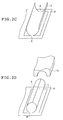
- FIG. 2C shows the plate member which has been press formed to some degree.
- the plate member 5 has been curled into U-shape.
- Such curling to the U-shape may be accomplished either by the press forming using the upper and lower mold halves 7a and 7b shown in FIG. 1B, or by the press forming using a mold having a different shape.
- the plate member which has been curled into the U-shape is further formed into a tube as shown in FIG. 2D by using a concave upper mold 7c.
- the procedure of press forming into the tube as shown in FIG. 2D may include several press forming steps using molds of different configurations.
- the seam of the tube formed by the press forming should be fluid tightly joined in some applications, for example, when the tube is used by passing a fluid therethrough as in the case of injection needle.
- the seam may be joined by using an adhesive. It is, however, preferable to weld the tube along its seam since the tube is made of a metal and is as thin as 1.3 mm in its outer diameter.
- the welding of the seam is preferably accomplished by melting the matrix of the tube, for example, by laser welding such as carbon dioxide laser welding, YAG laser welding, eximer laser welding, or the like among which the carbon dioxide laser welding and the YAG laser welding being particularly preferred in view of their wide availability, low cost, and adaptability to micromachining.
- the tube of the present invention can be obtained by cutting the tie portions between the thin plate and the plate member after the welding of the seam.
- the tube can be obtained by cutting the tie portions between the thin plate and the plate member after formation of the tube by the press forming of the plate member.
- the thus produced tube may be further processed depending on the intended use of the tube.
- the tube when the tube is to be used as an injection needle, the tube should be further processed, for example, to thereby provide the tube with an edge by a suitable conventional method.
- a tube whose inner surface has a Rf of up to 3 ⁇ m can be produced in a high yield, and a long drawing machine is not necessary.
- a plurality of tubes can be produced from one thin plate at a time by using a long thin plate having a width corresponding to a length of a tube and small diameter tubes whose inner surfaces are smooth as well as the outer surface can be produced at a lower cost.
- Tubes (tube 1, 2) each having an outer diameter of 0.35 mm, an inner diameter of 0.25 mm and a length of 18 mm were produced by press forming a thin plate of stainless steel (SUS304) having a thickness of 0.05 mm according to the procedure shown in FIGS. 1A, 1B, 2C and 2D.
- a micrograph was taken using 1LM21.
- FIG. 4B shows a micrograph of the inner surface of the tube in Example 1.
- a thin plate (SUS304) having a thickness of 0.17 mm was subjected to a conventional method utilizing a drawing process to thereby produce tubes (tube 1, 2) whose material and dimensions are the same as those in Example 1 (outer diameter: 0.35mm; inner diameter: 0.25 mm; length: 18 mm).
- the inner surfaces of the resulting tubes were subjected to the Rf measurement as in Example 1.
- the Rf measurements were shown in Table 1.
- FIG. 4A shows a micrograph of the inner surface of the tube in Comparative Example.
- Example 1 Comparative Example Outer diameter (mm) 0.35 0.35 Inner diameter (mm) 0.25 0.25 Length (mm) 18 18 R max ( ⁇ m) tube 1 tube 2 0.86 0.58 5.92 8.75
- the metal tube of the present invention has a small diameter, the inner surface thereof is kept smooth, and the resistance of a fluid passing through the tube is low. Dirt and foreign matters are less prone to adhere thereto. Therefore, the metal tube of the present invention can be suitably used in various applications requiring small diameter tubes, for example by forming into an injection needle.
- press forming is only necessary to obtain a tube having desired dimensions.
- a tube which has no creases on its inner surface as in a conventional production method utilizing the drawing and whose inner surface is kept smooth can be obtained.
- the tube described above can be produced at a low cost.
- a small diameter metal tube whose inner surface is smooth and its production method are provided.
- the metal tube has an inner diameter of up to 1.0 mm and its inner surface has a maximum height difference (Rf) in the surface roughness of up to 3 ⁇ m.
Landscapes
- Engineering & Computer Science (AREA)
- Mechanical Engineering (AREA)
- Infusion, Injection, And Reservoir Apparatuses (AREA)
- Metal Extraction Processes (AREA)
- Shaping Metal By Deep-Drawing, Or The Like (AREA)
- Superconductors And Manufacturing Methods Therefor (AREA)
- Bending Of Plates, Rods, And Pipes (AREA)
- Rigid Pipes And Flexible Pipes (AREA)
Applications Claiming Priority (2)
| Application Number | Priority Date | Filing Date | Title |
|---|---|---|---|
| JP2001334143A JP2003136142A (ja) | 2001-10-31 | 2001-10-31 | 金属製の管状体およびその製造方法 |
| JP2001334143 | 2001-10-31 |
Publications (3)
| Publication Number | Publication Date |
|---|---|
| EP1308221A2 true EP1308221A2 (de) | 2003-05-07 |
| EP1308221A3 EP1308221A3 (de) | 2003-12-17 |
| EP1308221B1 EP1308221B1 (de) | 2005-07-13 |
Family
ID=19149318
Family Applications (1)
| Application Number | Title | Priority Date | Filing Date |
|---|---|---|---|
| EP02024133A Expired - Lifetime EP1308221B1 (de) | 2001-10-31 | 2002-10-29 | Metallrohr und Verfahren zu seiner Herstellung |
Country Status (9)
| Country | Link |
|---|---|
| US (2) | US6915821B2 (de) |
| EP (1) | EP1308221B1 (de) |
| JP (1) | JP2003136142A (de) |
| KR (1) | KR20030036056A (de) |
| CN (1) | CN1419976A (de) |
| AT (1) | ATE299409T1 (de) |
| DE (1) | DE60205006T2 (de) |
| DK (1) | DK1308221T3 (de) |
| ES (1) | ES2244715T3 (de) |
Cited By (3)
| Publication number | Priority date | Publication date | Assignee | Title |
|---|---|---|---|---|
| US6877652B2 (en) * | 2001-12-27 | 2005-04-12 | Terumo Kabushiki Kaisha | Metal tubular body and manufacturing method thereof |
| US6915821B2 (en) * | 2001-10-31 | 2005-07-12 | Terumo Kabushiki Kaisha | Metal tube and its production method |
| EP2913118A4 (de) * | 2012-10-29 | 2016-06-08 | Hino Motors Ltd | Verfahren zur herstellung eines flachrohrs |
Families Citing this family (23)
| Publication number | Priority date | Publication date | Assignee | Title |
|---|---|---|---|---|
| PL203322B1 (pl) * | 2001-03-23 | 2009-09-30 | Nipro Corp | Zespół igły do zastrzyków |
| JP4394864B2 (ja) * | 2002-05-07 | 2010-01-06 | テルモ株式会社 | 金属製の管状体およびその製造方法 |
| US20040250404A1 (en) * | 2003-01-14 | 2004-12-16 | Cripsey Timothy J. | Process for press forming metal tubes |
| US20060096099A1 (en) * | 2003-05-08 | 2006-05-11 | Noble Metal Processing, Inc. | Automotive crush tip and method of manufacturing |
| DE102006020746A1 (de) * | 2006-05-04 | 2007-11-15 | Dünne, Heinz | Verschleißfestes Rohr mit Längsnaht |
| JP4874159B2 (ja) | 2007-04-20 | 2012-02-15 | 三洋電機株式会社 | 固体電解コンデンサの製造方法 |
| JP2010077982A (ja) * | 2008-09-24 | 2010-04-08 | Panasonic Corp | 開閉装置及びその製造方法 |
| EP2260764A1 (de) * | 2009-06-10 | 2010-12-15 | F. Hoffmann-La Roche AG | Mikronadel und Verfahren zu deren Herstellung |
| KR101213223B1 (ko) | 2009-07-07 | 2013-01-09 | 한국전자통신연구원 | 할로우를 가지는 미세 바늘 및 미세 바늘 구조체의 제조 방법 |
| JP5696357B2 (ja) * | 2009-11-27 | 2015-04-08 | セイコーエプソン株式会社 | 搬送ローラーの製造方法、搬送ローラー、印刷装置 |
| US9982496B2 (en) * | 2011-07-26 | 2018-05-29 | Innovex Downhole Solutions, Inc. | Rolled tubular centralizer |
| US20140296797A1 (en) * | 2011-11-04 | 2014-10-02 | Nipro Corporation | Injection needle |
| CN102601266B (zh) * | 2012-03-07 | 2014-12-17 | 吴敏 | 一种自动卷环装置及其操作方法 |
| KR101419879B1 (ko) * | 2012-12-28 | 2014-07-17 | 재단법인 포항산업과학연구원 | 튜브 제조 장치 및 그 방법 |
| JP6129576B2 (ja) * | 2013-02-18 | 2017-05-17 | 岡野工業株式会社 | 中空ねじの製造方法及び中空ねじ |
| RU2640486C2 (ru) * | 2013-05-20 | 2018-01-09 | ДжФЕ СТИЛ КОРПОРЕЙШН | Гибочный пресс, способ прессовой гибки, устройство для производства стальных труб и способ производства стальных труб |
| TWI551370B (zh) * | 2013-06-25 | 2016-10-01 | Method of manufacturing hollow tube | |
| CN104740731A (zh) * | 2013-12-27 | 2015-07-01 | 苏州和林精密科技有限公司 | 一种无缝无痛针头及制备方法 |
| JP6576250B2 (ja) * | 2014-01-31 | 2019-09-18 | テルモ株式会社 | 医療用の穿刺針及び穿刺針の製造方法 |
| TWD172383S (zh) * | 2015-03-17 | 2015-12-11 | 溫芫鋐 | 來令片散熱結構之部分 |
| CN106181266A (zh) * | 2016-08-27 | 2016-12-07 | 江苏金达电热电器有限公司 | 一种加热辐射管外壳成型设备及成型方法 |
| JP7188225B2 (ja) * | 2019-03-26 | 2022-12-13 | 富士フイルムビジネスイノベーション株式会社 | インパクトプレス加工金属筒体 |
| CN117086152B (zh) * | 2023-09-08 | 2025-11-21 | 石家庄旭东机械制造有限公司 | 一种中厚板直径加长锥形管加工装备 |
Family Cites Families (17)
| Publication number | Priority date | Publication date | Assignee | Title |
|---|---|---|---|---|
| US2855929A (en) * | 1955-06-20 | 1958-10-14 | Becton Dickinson Co | Venting needle |
| NL286398A (de) * | 1961-12-08 | 1900-01-01 | ||
| JPS61103438A (ja) * | 1984-10-26 | 1986-05-21 | ナカムラ産業株式会社 | 糸付縫合針とその製造方法 |
| EP0232444A1 (de) * | 1986-02-19 | 1987-08-19 | Yasuo Nakamura | Chirurgische Nähnadel und Verfahren zur Herstellung |
| US4785868A (en) * | 1987-06-04 | 1988-11-22 | Titan Medical, Inc. | Medical needle and method for making |
| JPH0794090B2 (ja) * | 1989-11-01 | 1995-10-11 | 工業技術院長 | 小径管内面の電解砥粒超鏡面仕上げ方法 |
| JPH03284264A (ja) * | 1990-03-30 | 1991-12-13 | Ngk Insulators Ltd | セラミックス製注射針 |
| JPH07319326A (ja) * | 1994-05-26 | 1995-12-08 | Fuji Xerox Co Ltd | 感光体の駆動方法およびフランジ付き感光体 |
| US5640874A (en) * | 1995-06-02 | 1997-06-24 | United States Surgical Corporation | Progressive die/carrier apparatus and method of forming surgical needles and/or incision members |
| JPH09308910A (ja) | 1996-05-17 | 1997-12-02 | Kyoritsu Seiki:Kk | パイプ材及びその製造方法 |
| US5954104A (en) * | 1997-02-28 | 1999-09-21 | Abbott Laboratories | Container cap assembly having an enclosed penetrator |
| US6202465B1 (en) * | 1999-03-05 | 2001-03-20 | Micro Stamping Corporation | Method for forming endoscopic instrument body |
| CA2303732C (en) * | 1999-04-09 | 2010-05-25 | Daido Tokushuko Kabushiki Kaisha | Multi-layered anti-coking heat resisting metal tube and the method for manufacturing thereof |
| JP2001225106A (ja) | 2000-02-14 | 2001-08-21 | Tokin Corp | 形状記憶合金チューブ及びその製造方法 |
| CA2349137C (en) * | 2000-06-12 | 2008-01-08 | Daido Tokushuko Kabushiki Kaisha | Multi-layered anti-coking heat resistant metal tube and method for manufacture thereof |
| JP2003136142A (ja) * | 2001-10-31 | 2003-05-14 | Terumo Corp | 金属製の管状体およびその製造方法 |
| JP2004001053A (ja) * | 2002-06-03 | 2004-01-08 | Terumo Corp | 金属製の管状体及びその製造方法 |
-
2001
- 2001-10-31 JP JP2001334143A patent/JP2003136142A/ja active Pending
-
2002
- 2002-10-29 ES ES02024133T patent/ES2244715T3/es not_active Expired - Lifetime
- 2002-10-29 EP EP02024133A patent/EP1308221B1/de not_active Expired - Lifetime
- 2002-10-29 AT AT02024133T patent/ATE299409T1/de not_active IP Right Cessation
- 2002-10-29 DE DE60205006T patent/DE60205006T2/de not_active Expired - Lifetime
- 2002-10-29 DK DK02024133T patent/DK1308221T3/da active
- 2002-10-30 US US10/283,291 patent/US6915821B2/en not_active Expired - Lifetime
- 2002-10-30 KR KR1020020066587A patent/KR20030036056A/ko not_active Ceased
- 2002-10-31 CN CN02147989A patent/CN1419976A/zh active Pending
-
2005
- 2005-07-08 US US11/176,329 patent/US7104103B2/en not_active Expired - Lifetime
Cited By (5)
| Publication number | Priority date | Publication date | Assignee | Title |
|---|---|---|---|---|
| US6915821B2 (en) * | 2001-10-31 | 2005-07-12 | Terumo Kabushiki Kaisha | Metal tube and its production method |
| US7104103B2 (en) | 2001-10-31 | 2006-09-12 | Terumo Kabushiki Kaisha | Method for producing a metal tube |
| US6877652B2 (en) * | 2001-12-27 | 2005-04-12 | Terumo Kabushiki Kaisha | Metal tubular body and manufacturing method thereof |
| US7587820B2 (en) | 2001-12-27 | 2009-09-15 | Terumo Kabushiki Kaisha | Metal tubular body and manufacturing method thereof |
| EP2913118A4 (de) * | 2012-10-29 | 2016-06-08 | Hino Motors Ltd | Verfahren zur herstellung eines flachrohrs |
Also Published As
| Publication number | Publication date |
|---|---|
| EP1308221A3 (de) | 2003-12-17 |
| US20050241357A1 (en) | 2005-11-03 |
| EP1308221B1 (de) | 2005-07-13 |
| KR20030036056A (ko) | 2003-05-09 |
| DK1308221T3 (da) | 2005-08-08 |
| ATE299409T1 (de) | 2005-07-15 |
| DE60205006D1 (de) | 2005-08-18 |
| US6915821B2 (en) | 2005-07-12 |
| ES2244715T3 (es) | 2005-12-16 |
| US20030089414A1 (en) | 2003-05-15 |
| US7104103B2 (en) | 2006-09-12 |
| DE60205006T2 (de) | 2006-04-20 |
| JP2003136142A (ja) | 2003-05-14 |
| CN1419976A (zh) | 2003-05-28 |
Similar Documents
| Publication | Publication Date | Title |
|---|---|---|
| EP1308221B1 (de) | Metallrohr und Verfahren zu seiner Herstellung | |
| US6883552B2 (en) | Metal tube and its production method | |
| EP1361018B1 (de) | Metallischer Rohrkörper und Verfahren zu seiner Herstellung | |
| EP1323484B1 (de) | Metallrohr und Verfahren zu seiner Herstellung | |
| EP3597322B1 (de) | Presswerkzeug und verfahren zur herstellung von stahlrohren | |
| JP4473234B2 (ja) | 金属製の管状体およびその製造方法 | |
| JP4194823B2 (ja) | 金属製の管状体およびその製造方法 | |
| JP2007038021A (ja) | 金属製の注射針 | |
| JPH02155140A (ja) | 陰極線管用電子銃電極構体の製造方法 | |
| JPH02179326A (ja) | 板材成形方法 |
Legal Events
| Date | Code | Title | Description |
|---|---|---|---|
| PUAI | Public reference made under article 153(3) epc to a published international application that has entered the european phase |
Free format text: ORIGINAL CODE: 0009012 |
|
| AK | Designated contracting states |
Designated state(s): AT BE BG CH CY CZ DE DK EE ES FI FR GB GR IE IT LI LU MC NL PT SE SK TR |
|
| AX | Request for extension of the european patent |
Extension state: AL LT LV MK RO SI |
|
| PUAL | Search report despatched |
Free format text: ORIGINAL CODE: 0009013 |
|
| RIC1 | Information provided on ipc code assigned before grant |
Ipc: 7B 21C 37/06 A Ipc: 7A 61M 25/00 B Ipc: 7B 21G 1/08 B |
|
| AK | Designated contracting states |
Kind code of ref document: A3 Designated state(s): AT BE BG CH CY CZ DE DK EE ES FI FR GB GR IE IT LI LU MC NL PT SE SK TR |
|
| AX | Request for extension of the european patent |
Extension state: AL LT LV MK RO SI |
|
| 17P | Request for examination filed |
Effective date: 20040303 |
|
| 17Q | First examination report despatched |
Effective date: 20040712 |
|
| AKX | Designation fees paid |
Designated state(s): AT BE BG CH CY CZ DE DK EE ES FI FR GB GR IE IT LI LU MC NL PT SE SK TR |
|
| GRAP | Despatch of communication of intention to grant a patent |
Free format text: ORIGINAL CODE: EPIDOSNIGR1 |
|
| GRAS | Grant fee paid |
Free format text: ORIGINAL CODE: EPIDOSNIGR3 |
|
| GRAA | (expected) grant |
Free format text: ORIGINAL CODE: 0009210 |
|
| AK | Designated contracting states |
Kind code of ref document: B1 Designated state(s): AT BE BG CH CY CZ DE DK EE ES FI FR GB GR IE IT LI LU MC NL PT SE SK TR |
|
| PG25 | Lapsed in a contracting state [announced via postgrant information from national office to epo] |
Ref country code: FI Free format text: LAPSE BECAUSE OF FAILURE TO SUBMIT A TRANSLATION OF THE DESCRIPTION OR TO PAY THE FEE WITHIN THE PRESCRIBED TIME-LIMIT Effective date: 20050713 Ref country code: AT Free format text: LAPSE BECAUSE OF FAILURE TO SUBMIT A TRANSLATION OF THE DESCRIPTION OR TO PAY THE FEE WITHIN THE PRESCRIBED TIME-LIMIT Effective date: 20050713 Ref country code: SK Free format text: LAPSE BECAUSE OF FAILURE TO SUBMIT A TRANSLATION OF THE DESCRIPTION OR TO PAY THE FEE WITHIN THE PRESCRIBED TIME-LIMIT Effective date: 20050713 Ref country code: EE Free format text: LAPSE BECAUSE OF FAILURE TO SUBMIT A TRANSLATION OF THE DESCRIPTION OR TO PAY THE FEE WITHIN THE PRESCRIBED TIME-LIMIT Effective date: 20050713 Ref country code: TR Free format text: LAPSE BECAUSE OF FAILURE TO SUBMIT A TRANSLATION OF THE DESCRIPTION OR TO PAY THE FEE WITHIN THE PRESCRIBED TIME-LIMIT Effective date: 20050713 Ref country code: CZ Free format text: LAPSE BECAUSE OF FAILURE TO SUBMIT A TRANSLATION OF THE DESCRIPTION OR TO PAY THE FEE WITHIN THE PRESCRIBED TIME-LIMIT Effective date: 20050713 |
|
| REG | Reference to a national code |
Ref country code: GB Ref legal event code: FG4D |
|
| REG | Reference to a national code |
Ref country code: CH Ref legal event code: EP |
|
| REG | Reference to a national code |
Ref country code: DK Ref legal event code: T3 |
|
| REG | Reference to a national code |
Ref country code: IE Ref legal event code: FG4D |
|
| REF | Corresponds to: |
Ref document number: 60205006 Country of ref document: DE Date of ref document: 20050818 Kind code of ref document: P |
|
| REG | Reference to a national code |
Ref country code: SE Ref legal event code: TRGR |
|
| REG | Reference to a national code |
Ref country code: CH Ref legal event code: NV Representative=s name: RITSCHER & PARTNER AG |
|
| PG25 | Lapsed in a contracting state [announced via postgrant information from national office to epo] |
Ref country code: GR Free format text: LAPSE BECAUSE OF FAILURE TO SUBMIT A TRANSLATION OF THE DESCRIPTION OR TO PAY THE FEE WITHIN THE PRESCRIBED TIME-LIMIT Effective date: 20051013 Ref country code: BG Free format text: LAPSE BECAUSE OF FAILURE TO SUBMIT A TRANSLATION OF THE DESCRIPTION OR TO PAY THE FEE WITHIN THE PRESCRIBED TIME-LIMIT Effective date: 20051013 |
|
| PG25 | Lapsed in a contracting state [announced via postgrant information from national office to epo] |
Ref country code: CY Free format text: LAPSE BECAUSE OF FAILURE TO SUBMIT A TRANSLATION OF THE DESCRIPTION OR TO PAY THE FEE WITHIN THE PRESCRIBED TIME-LIMIT Effective date: 20051029 |
|
| PG25 | Lapsed in a contracting state [announced via postgrant information from national office to epo] |
Ref country code: MC Free format text: LAPSE BECAUSE OF NON-PAYMENT OF DUE FEES Effective date: 20051031 Ref country code: LU Free format text: LAPSE BECAUSE OF NON-PAYMENT OF DUE FEES Effective date: 20051031 |
|
| REG | Reference to a national code |
Ref country code: ES Ref legal event code: FG2A Ref document number: 2244715 Country of ref document: ES Kind code of ref document: T3 |
|
| PG25 | Lapsed in a contracting state [announced via postgrant information from national office to epo] |
Ref country code: PT Free format text: LAPSE BECAUSE OF FAILURE TO SUBMIT A TRANSLATION OF THE DESCRIPTION OR TO PAY THE FEE WITHIN THE PRESCRIBED TIME-LIMIT Effective date: 20051219 |
|
| ET | Fr: translation filed | ||
| PLBE | No opposition filed within time limit |
Free format text: ORIGINAL CODE: 0009261 |
|
| STAA | Information on the status of an ep patent application or granted ep patent |
Free format text: STATUS: NO OPPOSITION FILED WITHIN TIME LIMIT |
|
| 26N | No opposition filed |
Effective date: 20060418 |
|
| REG | Reference to a national code |
Ref country code: CH Ref legal event code: PCAR Free format text: RITSCHER & PARTNER AG;RESIRAIN 1;8125 ZOLLIKERBERG (CH) |
|
| REG | Reference to a national code |
Ref country code: CH Ref legal event code: PFA Owner name: TERUMO KABUSHIKI KAISHA, JP Free format text: FORMER OWNER: TERUMO KABUSHIKI KAISHA, JP |
|
| REG | Reference to a national code |
Ref country code: FR Ref legal event code: PLFP Year of fee payment: 15 |
|
| REG | Reference to a national code |
Ref country code: DE Ref legal event code: R082 Ref document number: 60205006 Country of ref document: DE Representative=s name: TBK, DE Ref country code: DE Ref legal event code: R081 Ref document number: 60205006 Country of ref document: DE Owner name: TERUMO KABUSHIKI KAISHA, JP Free format text: FORMER OWNERS: TERUMO K.K., TOKIO/TOKYO, JP; OKANO KOGYO CO., LTD., TOKIO/TOKYO, JP |
|
| REG | Reference to a national code |
Ref country code: CH Ref legal event code: PUEA Owner name: TERUMO KABUSHIKI KAISHA, JP Free format text: FORMER OWNER: TERUMO KABUSHIKI KAISHA, JP |
|
| REG | Reference to a national code |
Ref country code: GB Ref legal event code: 732E Free format text: REGISTERED BETWEEN 20170706 AND 20170715 |
|
| REG | Reference to a national code |
Ref country code: NL Ref legal event code: PD Owner name: TERUMO KABUSHIKI KAISHA; JP Free format text: DETAILS ASSIGNMENT: CHANGE OF OWNER(S), ASSIGNMENT; FORMER OWNER NAME: TERUMO KABUSHIKI KAISHA Effective date: 20170524 |
|
| REG | Reference to a national code |
Ref country code: FR Ref legal event code: PLFP Year of fee payment: 16 |
|
| REG | Reference to a national code |
Ref country code: FR Ref legal event code: TP Owner name: TERUMO KABUSHIKI KAISHA, JP Effective date: 20171016 |
|
| PGFP | Annual fee paid to national office [announced via postgrant information from national office to epo] |
Ref country code: ES Payment date: 20171106 Year of fee payment: 16 |
|
| REG | Reference to a national code |
Ref country code: FR Ref legal event code: PLFP Year of fee payment: 17 |
|
| REG | Reference to a national code |
Ref country code: ES Ref legal event code: FD2A Effective date: 20191204 |
|
| PG25 | Lapsed in a contracting state [announced via postgrant information from national office to epo] |
Ref country code: ES Free format text: LAPSE BECAUSE OF NON-PAYMENT OF DUE FEES Effective date: 20181030 |
|
| PGFP | Annual fee paid to national office [announced via postgrant information from national office to epo] |
Ref country code: FR Payment date: 20210913 Year of fee payment: 20 Ref country code: IT Payment date: 20210910 Year of fee payment: 20 Ref country code: NL Payment date: 20210915 Year of fee payment: 20 |
|
| PGFP | Annual fee paid to national office [announced via postgrant information from national office to epo] |
Ref country code: BE Payment date: 20210916 Year of fee payment: 20 Ref country code: GB Payment date: 20210922 Year of fee payment: 20 |
|
| PGFP | Annual fee paid to national office [announced via postgrant information from national office to epo] |
Ref country code: SE Payment date: 20211012 Year of fee payment: 20 Ref country code: DE Payment date: 20210923 Year of fee payment: 20 Ref country code: IE Payment date: 20211012 Year of fee payment: 20 Ref country code: DK Payment date: 20211012 Year of fee payment: 20 |
|
| PGFP | Annual fee paid to national office [announced via postgrant information from national office to epo] |
Ref country code: CH Payment date: 20211014 Year of fee payment: 20 |
|
| REG | Reference to a national code |
Ref country code: DE Ref legal event code: R071 Ref document number: 60205006 Country of ref document: DE |
|
| REG | Reference to a national code |
Ref country code: CH Ref legal event code: PL Ref country code: DK Ref legal event code: EUP Expiry date: 20221029 |
|
| REG | Reference to a national code |
Ref country code: NL Ref legal event code: MK Effective date: 20221028 |
|
| REG | Reference to a national code |
Ref country code: BE Ref legal event code: MK Effective date: 20221029 |
|
| REG | Reference to a national code |
Ref country code: GB Ref legal event code: PE20 Expiry date: 20221028 |
|
| REG | Reference to a national code |
Ref country code: SE Ref legal event code: EUG |
|
| REG | Reference to a national code |
Ref country code: IE Ref legal event code: MK9A |
|
| PG25 | Lapsed in a contracting state [announced via postgrant information from national office to epo] |
Ref country code: IE Free format text: LAPSE BECAUSE OF EXPIRATION OF PROTECTION Effective date: 20221029 Ref country code: GB Free format text: LAPSE BECAUSE OF EXPIRATION OF PROTECTION Effective date: 20221028 |