EP1306282B1 - Verfahren zur Sicherheitskontrolle der Neigung eines Schienenfahrzeuges - Google Patents
Verfahren zur Sicherheitskontrolle der Neigung eines Schienenfahrzeuges Download PDFInfo
- Publication number
- EP1306282B1 EP1306282B1 EP02292465A EP02292465A EP1306282B1 EP 1306282 B1 EP1306282 B1 EP 1306282B1 EP 02292465 A EP02292465 A EP 02292465A EP 02292465 A EP02292465 A EP 02292465A EP 1306282 B1 EP1306282 B1 EP 1306282B1
- Authority
- EP
- European Patent Office
- Prior art keywords
- tilt
- train
- tilting
- track
- values
- Prior art date
- Legal status (The legal status is an assumption and is not a legal conclusion. Google has not performed a legal analysis and makes no representation as to the accuracy of the status listed.)
- Expired - Lifetime
Links
Images


Classifications
-
- B—PERFORMING OPERATIONS; TRANSPORTING
- B61—RAILWAYS
- B61L—GUIDING RAILWAY TRAFFIC; ENSURING THE SAFETY OF RAILWAY TRAFFIC
- B61L3/00—Devices along the route for controlling devices on the vehicle or train, e.g. to release brake or to operate a warning signal
- B61L3/02—Devices along the route for controlling devices on the vehicle or train, e.g. to release brake or to operate a warning signal at selected places along the route, e.g. intermittent control simultaneous mechanical and electrical control
- B61L3/08—Devices along the route for controlling devices on the vehicle or train, e.g. to release brake or to operate a warning signal at selected places along the route, e.g. intermittent control simultaneous mechanical and electrical control controlling electrically
- B61L3/12—Devices along the route for controlling devices on the vehicle or train, e.g. to release brake or to operate a warning signal at selected places along the route, e.g. intermittent control simultaneous mechanical and electrical control controlling electrically using magnetic or electrostatic induction; using radio waves
- B61L3/128—Devices along the route for controlling devices on the vehicle or train, e.g. to release brake or to operate a warning signal at selected places along the route, e.g. intermittent control simultaneous mechanical and electrical control controlling electrically using magnetic or electrostatic induction; using radio waves for control of tilting trains by external control devices, e.g. by Eurobalise
-
- B—PERFORMING OPERATIONS; TRANSPORTING
- B61—RAILWAYS
- B61F—RAIL VEHICLE SUSPENSIONS, e.g. UNDERFRAMES, BOGIES OR ARRANGEMENTS OF WHEEL AXLES; RAIL VEHICLES FOR USE ON TRACKS OF DIFFERENT WIDTH; PREVENTING DERAILING OF RAIL VEHICLES; WHEEL GUARDS, OBSTRUCTION REMOVERS OR THE LIKE FOR RAIL VEHICLES
- B61F5/00—Constructional details of bogies; Connections between bogies and vehicle underframes; Arrangements or devices for adjusting or allowing self-adjustment of wheel axles or bogies when rounding curves
- B61F5/02—Arrangements permitting limited transverse relative movements between vehicle underframe or bolster and bogie; Connections between underframes and bogies
- B61F5/22—Guiding of the vehicle underframes with respect to the bogies
Definitions
- the invention relates to a method of securely controlling the tilting of a railway vehicle and more particularly to a control method ensuring a high level of safety against collisions with commuter vehicles.
- the patent DE-A-44 36 137 teaches a similar device to the patent US-A-4,355,582 wherein the limitation of the vehicle movement is a function of the radius of curvature and acceleration of the vehicle.
- an object of the present invention is to provide a method for the safe control of the tilting of a railway vehicle which provides increased safety by ensuring that the outline of the railway vehicle always remains inside a safe template, called Free Obstacle Template (GLO), defines at any point of the railway.
- GLO Free Obstacle Template
- the subject of the invention is a method for the secure control of the tilting of a railway vehicle traveling on a railway, characterized in that the limit values of the authorized tilt are assigned to different cantons of the railway ( ⁇ 1 , ⁇ 2 ) representative of a safety gauge inside which the train can pendulate without risk of collision with the infrastructures arranged near the track or with a vehicle coming in the opposite direction, and in that it is forbidden any tilting of the vehicle beyond authorized tilt limit values ( ⁇ 1 , ⁇ 2 ) assigned to the track canton on which the vehicle is located.
- a pendular rail vehicle 5 consisting of three cars V 1 , V 2 , V 3 comprising an automatic tilting control device of known type, for example as described in the application, will be considered.
- FR 2,794,707 triggering the tilting of the various cars of the vehicle according to the geometry of the railway and the kinematics of the vehicle.
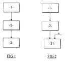
- FIG. 1 represents the general architecture of a first embodiment of the method of safe control of tilting according to the invention. This method, which is implemented by a safety system for automatic protection on board the vehicle 5 operates in parallel and independently of the automatic steering device of the tilt equipping the vehicle 5.
- the method of safety control of tilting comprises a first step 1 corresponding to the acquisition, by the system safety automatic protection board on board the railway vehicle 5, indicative values of the limit tilt ( ⁇ 1 , ⁇ 2 ) assigned to the track of the canton on which the railway vehicle will arrive.
- the acquisition of the indicative limit tilting values ( ⁇ 1 , ⁇ 2 ) is preferably carried out by means of beacons 6 arranged along the railway track, as represented in FIG. 4, each beacon 6 allowing the acquisition by a vehicle indicative limiting tilt values ( ⁇ 1 , ⁇ 2 ) defined for the channel block disposed downstream of the beacon 6.
- the indicative limit tilt values ( ⁇ 1 , ⁇ 2 ) read from the beacons 6 correspond to the limit values of allowed tilting ( ⁇ 1 , ⁇ 2 ) for a railway vehicle of a given type preferably corresponding to the model of a traveling commuter vehicle. most commonly on the path concerned.
- these values are then corrected by means of correction coefficients, stored in the automatic protective safety system. boarded on the pendular vehicle concerned, to obtain the authorized tilt limit values ( ⁇ 1 , ⁇ 2 ) of the vehicle actually traveling on the track.
- Such a correction thus makes it possible to take into account the different dimensions of the pendular vehicles that can circulate on the same track.
- the safety system for automatic protection on board the vehicle calculates, for each of the cars V i , i ⁇ [1,3], constituting the railway vehicle 5, the different limit values of the permitted tilt ( corresponding ⁇ 1i , ⁇ 2i ). To do this, the safety protection system calculates at every moment the position of the various cars with respect to the beacons 6 arranged along the track, for example by using the vehicle speed and the known lengths of the cars V i .
- these allowed tilt limit values ( ⁇ 1i , ⁇ 2i ) correspond respectively to the inclination that a vehicle body can take. on both sides of the plane OZ orthogonal to the plane of the rails for a given channel canton.
- These allowed tilt limit values ( ⁇ 1i , ⁇ 2i ) are representative of a security template also called Free Obstacle Jig (GLO) within which the vehicle can pendulate without risk of collision with a track infrastructure or possibly with a vehicle traveling on a parallel track.
- GLO Free Obstacle Jig
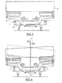
- These mechanical locking means 7, shown in more detail in FIGS. 5 and 6, consist, for example, of two vertically displaceable abutments 7 fixed to the bogie frame 10 of the vehicle, the latter supporting the body 11 of the vehicle via of a tilting cross member 8 articulated by means of connecting rods 9 according to the bogie described in the patent application FR 2 756 241 filed by the plaintiff.
- the stops 7 are formed by hydraulic cylinders arranged on each side of the bogie frame 10 and have an end capable of moving vertically under the tilting beam 8.
- a secure control of the positioning of each of the abutments 7 is achieved using security sensors on the cylinders and a procedure for emergency stop of the vehicle or operation reduced tilting is triggered when a fault is detected in the positioning of the stops 7.
- the location of the tags along the railway will be adapted to take into account the time required for the stops to move.
- the beacons announcing a next sector of lane in which the limit values of tilting are more restrictive will be placed upstream of the actual junction with the next lane sector, so that the stops are already in their more restrictive position when the vehicle actually reaches the junction with the next sector.
- the beacons announcing a future lane sector in which the limit values of tilting allowed are less restrictive will be placed at the right or slightly downstream of the real junction with the next sector.
- Such a method of safety control of tilting has the advantage of preventing the various cars of the vehicle from coming out of the Free Obstacle Jig (GLO) and thus to ensure increased safety by limiting the risk of collision of the vehicle with known infrastructure disposed along the track, for example in case of failure of the automatic control device of the tilt.
- this security control method operates in parallel and independently of the automatic control device of the tilt and thus ensures all of the security required for such a system.
- the automatic control device of the tilt can then be a servo which no longer needs to be treated safely.
- the security control method according to the invention may advantageously be integrated as an additional function to the automatic train protection system, usually called ATP system, which generally equips the trains.
- FIG. 2 represents a second embodiment of the method of safe control of tilting according to the invention implemented by an on-board protective safety system 20.
- the security control method comprises steps 1 and 2 which remain unchanged with respect to those described in the first embodiment but includes a step 31, replacing step 3 previously described, during of which the onboard automatic safety protection system 20 receives a measurement of the inclination ⁇ i of each of the cars V i of the vehicle, as is schematically represented in FIG. 7.
- These measurements ⁇ i are provided by safety sensors d inclination 21 present on the bogies and also used by the automatic control device of the tilt equipping the vehicle 5.
- the on-board automatic protection safety system 20 compares the values ⁇ i transmitted by the sensors with the allowed tilt limit values ( ⁇ 1i , ⁇ 2i ) obtained during step 2 of the method in order to to check that the inclination ⁇ i of each of the cars remains within the values authorized by the GLO template, namely ⁇ 1i ⁇ ⁇ i ⁇ ⁇ 2i .
- a safety procedure is triggered.
- This safety procedure may result, for the car V i concerned by the fault, by a safe inhibition of orders issued by the automatic tilting control device, accompanied by a zero setting of the degree of inclination of the body 11, and / or more safely by an emergency stop procedure of the vehicle 5.
- Such an embodiment of the safety control method has the advantage of not requiring additional mechanical stops on the bogies of the vehicle.
- the automatic tilt protection system incorporates a reaction time limiting the performance of the process.
- the acquisition of the authorized tilt limit values performed during the first step may also be performed through a database on board the rail vehicle, this basis containing all the limit values for tilting authorized for the different cantons of the railway on which the railway vehicle is traveling.
- the authorized tilt limit values of the track canton on which the vehicle is about to travel are extracted from the database by knowing the position of the railway vehicle on the railway.
Landscapes
- Engineering & Computer Science (AREA)
- Mechanical Engineering (AREA)
- Train Traffic Observation, Control, And Security (AREA)
- Vehicle Body Suspensions (AREA)
- Electric Propulsion And Braking For Vehicles (AREA)
- Traffic Control Systems (AREA)
Claims (8)
- Verfahren zur Sicherheitskontrolle der Neigung eines auf einem Schienenweg fahrenden Schienenfahrzeugs (5), wobei das Fahrzeug (5) N Wagen aufweist, deren Neigung von einer automatischen Fernsteuervorrichtung gesteuert wird, welche das Kippen der Wagen in Abhängigkeit von der Kinematik des Fahrzeugs und der Geometrie des Weges auslöst, dadurch gekennzeichnet, dass verschiedenen Abschnitten des Schienenweges zulässige Neigungsgrenzwerte (β1, β2) zugeordnet werden, welche repräsentativ sind für eine Sicherheitsbegrenzung, innerhalb derer der Zug sich neigen kann ohne die Gefahr mit den in der Nähe des Schienenweges angeordneten Infrastrukturen oder mit einem entgegen kommenden Fahrzeug zusammenzustoßen, und dass unabhängig von den Steuerbefehlen, die von der automatischen Fernsteuervorrichtung für die Neigung ausgesandt werden, für jeden Wagen i des Fahrzeugs (5), wobei i ∈ [1,N], jede Neigung jenseits der zulässigen Neigungsgrenzwerte (β1i, β2i), die dem Streckenabschnitt zugeordnet sind, auf welchem sich der Wagen i des Fahrzeugs befindet, verhindert wird.
- Verfahren zur Sicherheitskontrolle der Neigung gemäß Anspruch 1, dadurch gekennzeichnet, dass die Verhinderung der Neigung der verschiedenen Wagen i des Fahrzeugs, wobei i ∈ [1,N], über die zulässigen Neigungsgrenzwerte (β1i, β2i) hinaus mit Hilfe von beweglichen mechanischen Anschlägen (7) erreicht wird, welche auf dem Fahrgestellrahmen der Wagen aufliegen und von Stellgliedern gesteuert werden, wobei diese Anschläge die mechanische Blockierung der Neigung des Wagens über eine bestimmte Neigung hinaus sicherstellen, wobei das Fahrzeug ein eingebautes Sicherheitssystem zum automatischen Schutz der Neigung aufweist, das präventiv die Verschiebung dieser mechanischen Anschläge (7) auf jedem Fahrgestell insbesondere in Abhängigkeit von der Kenntnis der zulässigen Neigungsgrenzwerte (β1i, β2i) fernsteuert.
- Verfahren zur Sicherheitskontrolle der Neigung gemäß Anspruch 2, dadurch gekennzeichnet, dass nach dem Aussenden der Befehle für die Fernsteuerung der Anschläge (7) das eingebaute Sicherheitssystem zum automatischen Schutz der Neigung eine Kontrolle der Positionierung der Anschläge (7) mit Hilfe von Messfühlern vornimmt.
- Verfahren zur Sicherheitskontrolle gemäß Anspruch 1, dadurch gekennzeichnet, dass die Verhinderung der Neigung der Wagen i über die zulässigen Neigungsgrenzwerte (β1i, β2i) hinaus mit Hilfe eines an Bord des Fahrzeugs eingebauten Sicherheitssystems zum automatischen Schutz der Neigung (20) durchgeführt wird, welches in jedem Augenblick mit Hilfe von Messfühlern die tatsächliche Neigung der Wagen des Fahrzeugs misst, wobei das Sicherheitssystem zum automatischen Schutz der Neigung (20) jeden von der automatischen Fernsteuervorrichtung für die Neigung ausgesandten Fernsteuerbefehl verhindert, der dazu tendiert, die Wagen des Fahrzeugs über die zulässigen Neigungsgrenzwerte (β1i, β2i) hinaus sich neigen zu lassen.
- Verfahren zur Sicherheitskontrolle der Neigung gemäß Anspruch 4, dadurch gekennzeichnet, dass eine Nullstellung des Neigungsgrades des Wagens zusammen mit einem Nothalt des Fahrzeugs (5) vorgenommen wird, wenn die für ein Fahrzeug i gemessenen Neigungswerte die zulässigen Neigungsgrenzwerte (β1i, β2i) für den Streckenabschnitt, auf dem sich der Wagen i befindet, überschreiten.
- Verfahren zur Sicherheitskontrolle der Neigung gemäß irgendeinem der Ansprüche 1 bis 5, dadurch gekennzeichnet, dass die Neigungsgrenzwerte (β1i, β2i) bezüglich des Streckenabschnitts, auf welchem das Fahrzeug (5) fährt, anhand von Richtwerten für die Grenzneigung (α1, α2) entwickelt werden, welche von dem in dem Fahrzeug (5) eingebauten Sicherheitssystem für den automatischen Schutz der Neigung anhand einer stromaufwärts von dem Streckenabschnitt angeordneten Markierung (6) gewonnen werden.
- Verfahren zur Sicherheitskontrolle der Neigung gemäß irgendeinem der Ansprüche 1 bis 5, dadurch gekennzeichnet, dass die Richtwerte für die Grenzneigung (α1, α2), die beim Passieren der Markierungen (6) für jeden der Streckenabschnitte gewonnen werden, auf welchem das Fahrzeug (5) fahren wird, in einem an Bord des Fahrzeugs (5) eingebauten Speicher gespeichert und von dem Sicherheitssystem zum automatischen Schutz der Neigung in Abhängigkeit von der Kenntnis der Position des Fahrzeugs (5) auf dem Schienenweg verarbeitet werden.
- Verfahren zur Sicherheitskontrolle der Neigung gemäß Anspruch 7, dadurch gekennzeichnet, dass diese von den Markierungen (6) übermittelten Richtwerte für die Grenzneigung (α1, α2) den zulässigen Neigungsgrenzwerten (β1i, β2i), die für ein Fahrzeug der gegebenen Art spezifisch sind, entsprechen, und dass wenn das auf der Strecke fahrende Fahrzeug (5) von einer anderen Art ist, das an Bord dieses Fahrzeugs eingebaute Sicherheitssystem zum automatischen Schutz der Neigung Koeffizienten für die Korrektur der Spezifizierung des Fahrzeugs besitzt, die ihm ermöglichen, die zulässigen Neigungsgrenzwerte (β1, β2) zu berechnen, die für die Art Fahrzeug (5) eingerichtet sind, welches tatsächlich auf dem Schienenweg fährt.
Applications Claiming Priority (2)
| Application Number | Priority Date | Filing Date | Title |
|---|---|---|---|
| FR0113661A FR2831126B1 (fr) | 2001-10-23 | 2001-10-23 | Procede de controle securitaire de la pendulation d'un vehicule ferroviaire |
| FR0113661 | 2001-10-23 |
Publications (2)
| Publication Number | Publication Date |
|---|---|
| EP1306282A1 EP1306282A1 (de) | 2003-05-02 |
| EP1306282B1 true EP1306282B1 (de) | 2007-12-05 |
Family
ID=8868599
Family Applications (1)
| Application Number | Title | Priority Date | Filing Date |
|---|---|---|---|
| EP02292465A Expired - Lifetime EP1306282B1 (de) | 2001-10-23 | 2002-10-07 | Verfahren zur Sicherheitskontrolle der Neigung eines Schienenfahrzeuges |
Country Status (6)
| Country | Link |
|---|---|
| US (1) | US6786159B2 (de) |
| EP (1) | EP1306282B1 (de) |
| AT (1) | ATE380139T1 (de) |
| CA (1) | CA2409243C (de) |
| DE (1) | DE60223889D1 (de) |
| FR (1) | FR2831126B1 (de) |
Families Citing this family (8)
| Publication number | Priority date | Publication date | Assignee | Title |
|---|---|---|---|---|
| DE10316497A1 (de) * | 2003-04-09 | 2005-01-05 | Bombardier Transportation Gmbh | Fahrwerk für ein Schienenfahrzeug mit verbesserter Querfederung |
| DE102009014866A1 (de) * | 2009-03-30 | 2010-10-28 | Bombardier Transportation Gmbh | Fahrzeug mit Wankkompensation |
| CN101695937B (zh) * | 2009-09-26 | 2011-05-04 | 李嘉斌 | 防止车厢倾翻的汽车 |
| CA2807223C (en) * | 2010-10-15 | 2014-05-13 | Nippon Sharyo, Ltd. | Vehicle body tilting device and vehicle body tilting method for rail vehicle |
| US20120203402A1 (en) * | 2011-02-07 | 2012-08-09 | International Business Machines Corporation | Intelligent Railway System for Preventing Accidents at Railway Passing Points and Damage to the Rail Track |
| CN108528474B (zh) * | 2018-04-02 | 2019-09-13 | 交控科技股份有限公司 | 地铁车辆限界检测方法和系统 |
| CN110758436B (zh) * | 2019-10-31 | 2020-08-04 | 青岛理工大学 | 高速列车侧滚动态行为主动控制系统 |
| CN111678496B (zh) * | 2020-06-19 | 2021-11-16 | 青岛中车四方轨道车辆有限公司 | 一种轨道车辆落成找平的预警方法 |
Family Cites Families (12)
| Publication number | Priority date | Publication date | Assignee | Title |
|---|---|---|---|---|
| FR2459168A1 (fr) * | 1979-06-21 | 1981-01-09 | Budd Co | Systeme de commande d'inclinaison associe a la caisse et a un bogie de vehicule ferroviaire |
| EP0420940B1 (de) * | 1988-06-24 | 1993-12-15 | ANF-Industrie | Kraftanlenkungsvorrichtung zur neigung oder querstabilisierung eines fahrzeugoberbaus |
| SE465667B (sv) * | 1989-07-13 | 1991-10-14 | Asea Brown Boveri | Anordning foer styrning av korglutning i kurvor foer spaarbundet fordon |
| US5285729A (en) * | 1989-07-13 | 1994-02-15 | Asea Brown Boveri Ab | Indication of snow packing for railway vehicles |
| DE3935740A1 (de) * | 1989-10-27 | 1991-05-02 | Gerd Dipl Ing Klenke | Steuerung fuer den neigungsfaehigen wagenkasten eines spurgebundenen fahrzeugs |
| DE4037672A1 (de) * | 1990-11-27 | 1992-06-04 | Man Ghh Schienenverkehr | Schienenfahrzeug |
| SE9401796D0 (sv) * | 1994-05-25 | 1994-05-25 | Asea Brown Boveri | Positionsstyrt system för lutning av vagnskorg vid järnvägsfordon |
| DE4436137A1 (de) * | 1994-10-10 | 1996-04-11 | Talbot Waggonfab | Verfahren zum Steuern der Querverschiebung eines Schienenfahrzeugs gegenüber seinem Fahrwerk |
| DE19520824C2 (de) * | 1995-05-30 | 1998-04-09 | Siemens Ag | Einrichtung zur punktförmigen Datenübertragung in Bahnanlagen |
| EP0860341B1 (de) * | 1997-02-22 | 2001-05-02 | TZN Forschungs- und Entwicklungszentrum Unterlüss GmbH | Verfahren und Vorrichtung zur Steuerung und/oder Regelung von Wagenkasten-Neigesystemen |
| FR2794707B1 (fr) | 1999-06-11 | 2003-03-14 | Alstom | Procede et dispositif de commande de l'inclinaison d'un vehicule ferroviaire pendulaire |
| FR2817527B1 (fr) * | 2000-12-04 | 2003-01-10 | Alstom | Procede et dispositif de localisation d'un vehicule sur une voie |
-
2001
- 2001-10-23 FR FR0113661A patent/FR2831126B1/fr not_active Expired - Fee Related
-
2002
- 2002-10-07 DE DE60223889T patent/DE60223889D1/de not_active Expired - Lifetime
- 2002-10-07 AT AT02292465T patent/ATE380139T1/de not_active IP Right Cessation
- 2002-10-07 EP EP02292465A patent/EP1306282B1/de not_active Expired - Lifetime
- 2002-10-16 US US10/270,656 patent/US6786159B2/en not_active Expired - Lifetime
- 2002-10-21 CA CA2409243A patent/CA2409243C/fr not_active Expired - Fee Related
Also Published As
| Publication number | Publication date |
|---|---|
| FR2831126B1 (fr) | 2004-05-28 |
| EP1306282A1 (de) | 2003-05-02 |
| US6786159B2 (en) | 2004-09-07 |
| US20030075071A1 (en) | 2003-04-24 |
| CA2409243A1 (fr) | 2003-04-23 |
| ATE380139T1 (de) | 2007-12-15 |
| CA2409243C (fr) | 2011-08-02 |
| FR2831126A1 (fr) | 2003-04-25 |
| DE60223889D1 (de) | 2008-01-17 |
Similar Documents
| Publication | Publication Date | Title |
|---|---|---|
| CA2339898C (fr) | Procede et dispositif de commande d'elements pilotes d'un vehicule ferroviaire | |
| EP0315704B1 (de) | Schleifmaschine für die Reprofilierung von Schienenköpfen | |
| US8074577B2 (en) | Structure of bifurvation and crossover site of guideway in guided vehicle transportation system | |
| EP2219931B1 (de) | Vorrichtung zum messen der bewegung eines selbstgesteuerten fahrzeugs | |
| CA2409243C (fr) | Procede de controle securitaire de la pendulation d'un vehicule ferroviaire | |
| EP3608195A1 (de) | Verfahren zur höhensteuerung eines fahrzeugs, und entsprechendes fahrzeug | |
| FR2759340A1 (fr) | Systeme de guidage le long d'au moins un rail au sol pour un essieu d'un vehicule routier | |
| CA3005046A1 (fr) | Procede optimise de gestion de la circulation d'un train et systeme de signalisation cbtc associe | |
| CA2354411C (fr) | Procede de guidage d'un dispositif destine a inserer des elements dans le sol pour la realisation d'un ouvrage et dispositif d'insertion d'au moins un element dans le sol utilisant un tel procede de guidage | |
| FR3070661A1 (fr) | Procede de controle de la circulation de vehicules dans un reseau | |
| FR2628375A1 (fr) | Procede et installation pour la commande automatique d'un vehicule guide | |
| BE897323A (fr) | Procede et dispositif de reconnaissance et de controle de position pour vehicules de transport | |
| JP4292791B2 (ja) | 鉄道車両における車体傾斜制御のフェールセーフ方法及び装置、鉄道車両 | |
| SE465667B (sv) | Anordning foer styrning av korglutning i kurvor foer spaarbundet fordon | |
| JP3015725B2 (ja) | 鉄道線路状態検知装置および方法ならびに車体姿勢制御装置 | |
| EP2905195A1 (de) | Messvorrichtung für ein schienenkopfprofil | |
| EP1157912B1 (de) | Schienenfahrzeug mit einem Endwagen mit vorgelagerter Fahrerkabine | |
| CA2962887A1 (fr) | Procede de gestion de circulation d'un vehicule ferroviaire avec protection anticollision laterale | |
| WO2018219699A1 (fr) | Procédure de réglage d'un système de guidage d'une machine de travaux ferroviaires, procédé et système de guidage associés | |
| FR2643599A1 (fr) | Systeme de transport collectif utilisant des vehicules equipes de roues a pneu, et vehicule utilise dans un tel systeme | |
| EP1826319B1 (de) | Verfahren und System zum Einführen von Elementen auf dem Boden, Auskunftaufzeichnungsmedium für dieses Verfahren | |
| FR2821600A1 (fr) | Appareil de controle automatique d'un train | |
| EP0329918B1 (de) | Verfahren zur Instandsetzung eines Gleises | |
| JP3231377B2 (ja) | 列車姿勢制御装置 | |
| ES2354960T3 (es) | Método y sistema de control de velocidad de un vehículo ferroviario. |
Legal Events
| Date | Code | Title | Description |
|---|---|---|---|
| REG | Reference to a national code |
Ref country code: SE Ref legal event code: TRGR |
|
| PUAI | Public reference made under article 153(3) epc to a published international application that has entered the european phase |
Free format text: ORIGINAL CODE: 0009012 |
|
| AK | Designated contracting states |
Designated state(s): AT BE BG CH CY CZ DE DK EE ES FI FR GB GR IE IT LI LU MC NL PT SE SK TR |
|
| AX | Request for extension of the european patent |
Extension state: AL LT LV MK RO SI |
|
| 17P | Request for examination filed |
Effective date: 20031103 |
|
| AKX | Designation fees paid |
Designated state(s): AT BE BG CH CY CZ DE DK EE ES FI FR GB GR IE IT LI LU MC NL PT SE SK TR |
|
| RAP1 | Party data changed (applicant data changed or rights of an application transferred) |
Owner name: ALSTOM |
|
| GRAP | Despatch of communication of intention to grant a patent |
Free format text: ORIGINAL CODE: EPIDOSNIGR1 |
|
| GRAS | Grant fee paid |
Free format text: ORIGINAL CODE: EPIDOSNIGR3 |
|
| GRAA | (expected) grant |
Free format text: ORIGINAL CODE: 0009210 |
|
| AK | Designated contracting states |
Kind code of ref document: B1 Designated state(s): AT BE BG CH CY CZ DE DK EE ES FI FR GB GR IE IT LI LU MC NL PT SE SK TR |
|
| REG | Reference to a national code |
Ref country code: GB Ref legal event code: FG4D Free format text: NOT ENGLISH |
|
| REG | Reference to a national code |
Ref country code: IE Ref legal event code: FG4D Free format text: LANGUAGE OF EP DOCUMENT: FRENCH |
|
| REG | Reference to a national code |
Ref country code: CH Ref legal event code: EP |
|
| REF | Corresponds to: |
Ref document number: 60223889 Country of ref document: DE Date of ref document: 20080117 Kind code of ref document: P |
|
| REG | Reference to a national code |
Ref country code: GR Ref legal event code: EP Ref document number: 20080400276 Country of ref document: GR |
|
| GBT | Gb: translation of ep patent filed (gb section 77(6)(a)/1977) |
Effective date: 20080227 |
|
| PG25 | Lapsed in a contracting state [announced via postgrant information from national office to epo] |
Ref country code: ES Free format text: LAPSE BECAUSE OF FAILURE TO SUBMIT A TRANSLATION OF THE DESCRIPTION OR TO PAY THE FEE WITHIN THE PRESCRIBED TIME-LIMIT Effective date: 20080316 Ref country code: NL Free format text: LAPSE BECAUSE OF FAILURE TO SUBMIT A TRANSLATION OF THE DESCRIPTION OR TO PAY THE FEE WITHIN THE PRESCRIBED TIME-LIMIT Effective date: 20071205 |
|
| PG25 | Lapsed in a contracting state [announced via postgrant information from national office to epo] |
Ref country code: FI Free format text: LAPSE BECAUSE OF FAILURE TO SUBMIT A TRANSLATION OF THE DESCRIPTION OR TO PAY THE FEE WITHIN THE PRESCRIBED TIME-LIMIT Effective date: 20071205 |
|
| NLV1 | Nl: lapsed or annulled due to failure to fulfill the requirements of art. 29p and 29m of the patents act | ||
| PG25 | Lapsed in a contracting state [announced via postgrant information from national office to epo] |
Ref country code: AT Free format text: LAPSE BECAUSE OF FAILURE TO SUBMIT A TRANSLATION OF THE DESCRIPTION OR TO PAY THE FEE WITHIN THE PRESCRIBED TIME-LIMIT Effective date: 20071205 |
|
| PG25 | Lapsed in a contracting state [announced via postgrant information from national office to epo] |
Ref country code: CZ Free format text: LAPSE BECAUSE OF FAILURE TO SUBMIT A TRANSLATION OF THE DESCRIPTION OR TO PAY THE FEE WITHIN THE PRESCRIBED TIME-LIMIT Effective date: 20071205 |
|
| PG25 | Lapsed in a contracting state [announced via postgrant information from national office to epo] |
Ref country code: PT Free format text: LAPSE BECAUSE OF FAILURE TO SUBMIT A TRANSLATION OF THE DESCRIPTION OR TO PAY THE FEE WITHIN THE PRESCRIBED TIME-LIMIT Effective date: 20080505 |
|
| REG | Reference to a national code |
Ref country code: IE Ref legal event code: FD4D |
|
| PLBE | No opposition filed within time limit |
Free format text: ORIGINAL CODE: 0009261 |
|
| STAA | Information on the status of an ep patent application or granted ep patent |
Free format text: STATUS: NO OPPOSITION FILED WITHIN TIME LIMIT |
|
| PG25 | Lapsed in a contracting state [announced via postgrant information from national office to epo] |
Ref country code: DK Free format text: LAPSE BECAUSE OF FAILURE TO SUBMIT A TRANSLATION OF THE DESCRIPTION OR TO PAY THE FEE WITHIN THE PRESCRIBED TIME-LIMIT Effective date: 20071205 Ref country code: DE Free format text: LAPSE BECAUSE OF FAILURE TO SUBMIT A TRANSLATION OF THE DESCRIPTION OR TO PAY THE FEE WITHIN THE PRESCRIBED TIME-LIMIT Effective date: 20080306 Ref country code: IE Free format text: LAPSE BECAUSE OF FAILURE TO SUBMIT A TRANSLATION OF THE DESCRIPTION OR TO PAY THE FEE WITHIN THE PRESCRIBED TIME-LIMIT Effective date: 20071205 |
|
| 26N | No opposition filed |
Effective date: 20080908 |
|
| PGFP | Annual fee paid to national office [announced via postgrant information from national office to epo] |
Ref country code: EE Payment date: 20081013 Year of fee payment: 7 |
|
| PGFP | Annual fee paid to national office [announced via postgrant information from national office to epo] |
Ref country code: SK Payment date: 20081006 Year of fee payment: 7 |
|
| BERE | Be: lapsed |
Owner name: ALSTOM Effective date: 20081031 |
|
| PG25 | Lapsed in a contracting state [announced via postgrant information from national office to epo] |
Ref country code: MC Free format text: LAPSE BECAUSE OF NON-PAYMENT OF DUE FEES Effective date: 20081031 |
|
| REG | Reference to a national code |
Ref country code: CH Ref legal event code: PL |
|
| PG25 | Lapsed in a contracting state [announced via postgrant information from national office to epo] |
Ref country code: CY Free format text: LAPSE BECAUSE OF FAILURE TO SUBMIT A TRANSLATION OF THE DESCRIPTION OR TO PAY THE FEE WITHIN THE PRESCRIBED TIME-LIMIT Effective date: 20071205 |
|
| PG25 | Lapsed in a contracting state [announced via postgrant information from national office to epo] |
Ref country code: BE Free format text: LAPSE BECAUSE OF NON-PAYMENT OF DUE FEES Effective date: 20081031 |
|
| PG25 | Lapsed in a contracting state [announced via postgrant information from national office to epo] |
Ref country code: CH Free format text: LAPSE BECAUSE OF NON-PAYMENT OF DUE FEES Effective date: 20081031 Ref country code: LI Free format text: LAPSE BECAUSE OF NON-PAYMENT OF DUE FEES Effective date: 20081031 |
|
| REG | Reference to a national code |
Ref country code: FR Ref legal event code: TP |
|
| REG | Reference to a national code |
Ref country code: EE Ref legal event code: MM4A Ref document number: E001791 Country of ref document: EE Effective date: 20091031 |
|
| REG | Reference to a national code |
Ref country code: SK Ref legal event code: MM4A Ref document number: E 3078 Country of ref document: SK Effective date: 20091007 |
|
| PG25 | Lapsed in a contracting state [announced via postgrant information from national office to epo] |
Ref country code: LU Free format text: LAPSE BECAUSE OF NON-PAYMENT OF DUE FEES Effective date: 20081007 Ref country code: EE Free format text: LAPSE BECAUSE OF NON-PAYMENT OF DUE FEES Effective date: 20091031 |
|
| PG25 | Lapsed in a contracting state [announced via postgrant information from national office to epo] |
Ref country code: SK Free format text: LAPSE BECAUSE OF NON-PAYMENT OF DUE FEES Effective date: 20091007 |
|
| PG25 | Lapsed in a contracting state [announced via postgrant information from national office to epo] |
Ref country code: IT Free format text: LAPSE BECAUSE OF NON-PAYMENT OF DUE FEES Effective date: 20081031 |
|
| REG | Reference to a national code |
Ref country code: FR Ref legal event code: TP Owner name: ALSTOM TRANSPORT TECHNOLOGIES, FR Effective date: 20141209 |
|
| REG | Reference to a national code |
Ref country code: FR Ref legal event code: PLFP Year of fee payment: 14 |
|
| REG | Reference to a national code |
Ref country code: GB Ref legal event code: 732E Free format text: REGISTERED BETWEEN 20151001 AND 20151007 |
|
| REG | Reference to a national code |
Ref country code: GB Ref legal event code: 732E Free format text: REGISTERED BETWEEN 20151119 AND 20151125 |
|
| REG | Reference to a national code |
Ref country code: FR Ref legal event code: PLFP Year of fee payment: 15 |
|
| REG | Reference to a national code |
Ref country code: FR Ref legal event code: PLFP Year of fee payment: 16 |
|
| REG | Reference to a national code |
Ref country code: FR Ref legal event code: CA Effective date: 20180103 |
|
| REG | Reference to a national code |
Ref country code: FR Ref legal event code: PLFP Year of fee payment: 17 |
|
| PGFP | Annual fee paid to national office [announced via postgrant information from national office to epo] |
Ref country code: TR Payment date: 20180924 Year of fee payment: 17 |
|
| PGFP | Annual fee paid to national office [announced via postgrant information from national office to epo] |
Ref country code: BG Payment date: 20191023 Year of fee payment: 18 Ref country code: SE Payment date: 20191021 Year of fee payment: 18 |
|
| PGFP | Annual fee paid to national office [announced via postgrant information from national office to epo] |
Ref country code: GR Payment date: 20191022 Year of fee payment: 18 Ref country code: FR Payment date: 20191028 Year of fee payment: 18 |
|
| PGFP | Annual fee paid to national office [announced via postgrant information from national office to epo] |
Ref country code: GB Payment date: 20191021 Year of fee payment: 18 |
|
| REG | Reference to a national code |
Ref country code: SE Ref legal event code: EUG |
|
| GBPC | Gb: european patent ceased through non-payment of renewal fee |
Effective date: 20201007 |
|
| PG25 | Lapsed in a contracting state [announced via postgrant information from national office to epo] |
Ref country code: GR Free format text: LAPSE BECAUSE OF NON-PAYMENT OF DUE FEES Effective date: 20210510 Ref country code: FR Free format text: LAPSE BECAUSE OF NON-PAYMENT OF DUE FEES Effective date: 20201031 Ref country code: BG Free format text: LAPSE BECAUSE OF NON-PAYMENT OF DUE FEES Effective date: 20210430 |
|
| PG25 | Lapsed in a contracting state [announced via postgrant information from national office to epo] |
Ref country code: SE Free format text: LAPSE BECAUSE OF NON-PAYMENT OF DUE FEES Effective date: 20201008 Ref country code: GB Free format text: LAPSE BECAUSE OF NON-PAYMENT OF DUE FEES Effective date: 20201007 |
|
| PG25 | Lapsed in a contracting state [announced via postgrant information from national office to epo] |
Ref country code: TR Free format text: LAPSE BECAUSE OF NON-PAYMENT OF DUE FEES Effective date: 20201007 |