EP1306237A2 - Suspension de roue de véhicule automobile - Google Patents
Suspension de roue de véhicule automobile Download PDFInfo
- Publication number
- EP1306237A2 EP1306237A2 EP02023591A EP02023591A EP1306237A2 EP 1306237 A2 EP1306237 A2 EP 1306237A2 EP 02023591 A EP02023591 A EP 02023591A EP 02023591 A EP02023591 A EP 02023591A EP 1306237 A2 EP1306237 A2 EP 1306237A2
- Authority
- EP
- European Patent Office
- Prior art keywords
- vehicle
- hydraulic
- wheel
- wheel suspension
- vehicle body
- Prior art date
- Legal status (The legal status is an assumption and is not a legal conclusion. Google has not performed a legal analysis and makes no representation as to the accuracy of the status listed.)
- Granted
Links
Images

Classifications
-
- B—PERFORMING OPERATIONS; TRANSPORTING
- B60—VEHICLES IN GENERAL
- B60G—VEHICLE SUSPENSION ARRANGEMENTS
- B60G7/00—Pivoted suspension arms; Accessories thereof
- B60G7/02—Attaching arms to sprung part of vehicle
-
- B—PERFORMING OPERATIONS; TRANSPORTING
- B60—VEHICLES IN GENERAL
- B60G—VEHICLE SUSPENSION ARRANGEMENTS
- B60G13/00—Resilient suspensions characterised by arrangement, location or type of vibration dampers
- B60G13/001—Arrangements for attachment of dampers
-
- B—PERFORMING OPERATIONS; TRANSPORTING
- B60—VEHICLES IN GENERAL
- B60G—VEHICLE SUSPENSION ARRANGEMENTS
- B60G17/00—Resilient suspensions having means for adjusting the spring or vibration-damper characteristics, for regulating the distance between a supporting surface and a sprung part of vehicle or for locking suspension during use to meet varying vehicular or surface conditions, e.g. due to speed or load
- B60G17/015—Resilient suspensions having means for adjusting the spring or vibration-damper characteristics, for regulating the distance between a supporting surface and a sprung part of vehicle or for locking suspension during use to meet varying vehicular or surface conditions, e.g. due to speed or load the regulating means comprising electric or electronic elements
- B60G17/0152—Resilient suspensions having means for adjusting the spring or vibration-damper characteristics, for regulating the distance between a supporting surface and a sprung part of vehicle or for locking suspension during use to meet varying vehicular or surface conditions, e.g. due to speed or load the regulating means comprising electric or electronic elements characterised by the action on a particular type of suspension unit
-
- B—PERFORMING OPERATIONS; TRANSPORTING
- B60—VEHICLES IN GENERAL
- B60G—VEHICLE SUSPENSION ARRANGEMENTS
- B60G2200/00—Indexing codes relating to suspension types
- B60G2200/10—Independent suspensions
- B60G2200/14—Independent suspensions with lateral arms
- B60G2200/144—Independent suspensions with lateral arms with two lateral arms forming a parallelogram
-
- B—PERFORMING OPERATIONS; TRANSPORTING
- B60—VEHICLES IN GENERAL
- B60G—VEHICLE SUSPENSION ARRANGEMENTS
- B60G2202/00—Indexing codes relating to the type of spring, damper or actuator
- B60G2202/20—Type of damper
- B60G2202/22—Rotary Damper
-
- B—PERFORMING OPERATIONS; TRANSPORTING
- B60—VEHICLES IN GENERAL
- B60G—VEHICLE SUSPENSION ARRANGEMENTS
- B60G2202/00—Indexing codes relating to the type of spring, damper or actuator
- B60G2202/40—Type of actuator
- B60G2202/41—Fluid actuator
- B60G2202/413—Hydraulic actuator
-
- B—PERFORMING OPERATIONS; TRANSPORTING
- B60—VEHICLES IN GENERAL
- B60G—VEHICLE SUSPENSION ARRANGEMENTS
- B60G2202/00—Indexing codes relating to the type of spring, damper or actuator
- B60G2202/40—Type of actuator
- B60G2202/41—Fluid actuator
- B60G2202/414—Fluid actuator using electrohydraulic valves
-
- B—PERFORMING OPERATIONS; TRANSPORTING
- B60—VEHICLES IN GENERAL
- B60G—VEHICLE SUSPENSION ARRANGEMENTS
- B60G2202/00—Indexing codes relating to the type of spring, damper or actuator
- B60G2202/40—Type of actuator
- B60G2202/41—Fluid actuator
- B60G2202/416—Fluid actuator using a pump, e.g. in the line connecting the lower chamber to the upper chamber of the actuator
-
- B—PERFORMING OPERATIONS; TRANSPORTING
- B60—VEHICLES IN GENERAL
- B60G—VEHICLE SUSPENSION ARRANGEMENTS
- B60G2202/00—Indexing codes relating to the type of spring, damper or actuator
- B60G2202/40—Type of actuator
- B60G2202/442—Rotary actuator
Definitions
- the invention relates to a wheel suspension for a motor vehicle, with an intermediate a vehicle wheel and the vehicle body arranged handlebars with his one Swivel end with the vehicle wheel and with its other end swivel with the Vehicle body is connected.
- Such a wheel suspension is known from the prior art, the handlebar for example via a ball joint on a wheel carrier that receives the vehicle wheel and is attached to the vehicle body via a rubber bearing.
- a shock absorber and a vehicle spring are also arranged by which the vehicle body is kept at a distance from the vehicle wheel.
- the Driving comfort is significantly dependent on the spring characteristic of the vehicle spring and dependent on the damping behavior of the shock absorber.
- a stabilizer can also be used to improve the roll characteristics when cornering be arranged between the two vehicle wheels of an axle of the motor vehicle.
- a torsion spring rod is often used as a stabilizer, with one end via a first pendulum support with a first of the two vehicle wheels and with his the other end is connected to the second vehicle wheel via a second pendulum support, the middle part of the stabilizer lying between the two ends on Vehicle body is stored.
- the pendulum supports can be used with the stabilizer opposite ends on the wheel carriers receiving the wheels or on the wheel carriers be attached to the vehicle body connecting rods.
- Such a wheel suspension has the disadvantage that the spring characteristic of Vehicle spring, the damping behavior of the shock absorber and the spring characteristic of the Stabilizer can not be changed regularly without one of these components to replace another with different properties.
- DE-AS 1 175 563 discloses the stabilizer in two separate Stabilizer bars to share, with a stabilizer bar firmly attached to the housing and the other stabilizer bar fixed to the shaft of a hydraulically operated one Swivel motor is connected. This makes it possible to twist the Motor shaft to preload the stabilizer against the motor housing in to actively influence the properties of the chassis in certain driving situations can. In particular, the roll behavior of the motor vehicle in cornering can thus be changed in a positive way.
- the object of the invention is to provide a wheel suspension for a motor vehicle in the properties of the connection of the vehicle wheel to the vehicle body separately and can be actively influenced.
- the wheel suspension for a motor vehicle has one between one Vehicle wheel and the vehicle body arranged handlebars with his one Swivel end with the vehicle wheel and with its other end swivel with the Vehicle body is coupled.
- the handlebar is a swivel motor with the Vehicle body connected and pivotable about the pivot axis of the swivel motor.
- the handlebar with its end facing away from the swivel motor on the vehicle wheel is attached, the distance between the Vehicle wheel and the vehicle body can be adjusted. Furthermore, about the Swivel motor both the suspension behavior and the damping behavior of the Vehicle wheel controllable relative to the vehicle body, so that the properties of the Connection of the vehicle wheel to the vehicle body can be influenced separately and actively can.
- the shock absorber used regularly in motor vehicles can omitted, the task of the swivel motor of the invention Suspension is perceptible.
- the swivel motor can directly with the handlebar and / or the vehicle body be connected. Is preferred between the swivel motor and the handlebar and / or between the swivel motor and the vehicle body but a mechanical one Damping element arranged, which jerky starting from the swivel motor Movements dampened to the handlebars and / or the vehicle body, thereby driving comfort is increased.
- a vehicle spring can be dispensed with with the wheel suspension according to the invention be when the swivel motor during use of the motor vehicle sufficient distance between the vehicle wheel and the vehicle body maintains.
- Such an operation of the swing motor brings a high Energy consumption with it, so that preferably between the vehicle wheel and the Vehicle body a vehicle spring is arranged, the indirectly or directly with one end with the vehicle wheel and the other end with the Vehicle body is connected.
- Vehicle spring There is a direct connection between the vehicle spring and the vehicle wheel for example the connection of one end of the vehicle spring to the vehicle wheel to understand the receiving wheel carrier.
- Vehicle spring With an indirect connection of the Vehicle spring with the vehicle wheel can also have one end of the vehicle spring on one the vehicle wheel be fastened to the chassis component connecting the vehicle body, the vehicle spring preferably having one end at a distance from the swivel motor or is attached to the handlebar for vehicle construction.
- the vehicle spring is attached at one end to the handlebar, it can go far in reach into the space between the vehicle wheel and the vehicle body.
- this area is often intended for other components in the motor vehicle, so that the handlebar preferably has a connection point to the swivel motor or the vehicle body has sufficient extension on which the Vehicle spring is attached with one end. It is thus possible to use the vehicle spring in only a small area inside or even completely outside of this To arrange space.
- the vehicle spring can be in the form of an elastomer spring or a steel spring, for example a coil spring, which is almost identical in terms of its spring characteristic Exhibits behavior under static and dynamic loads.
- the is preferred Vehicle spring is an air spring that has a spring characteristic that can be varied via air pressure and has differences in their dynamic and static behavior, so that the spring behavior of the wheel suspension in the desired way to different Driving situations can be adjusted without having to replace the vehicle spring itself have to.
- the swivel motor can be operated electrically or pneumatically. Is preferred however, the swivel motor is hydraulically operated and is connected to a hydraulic line regulated hydraulic pump connected as a hydraulically operated swivel motor can regularly be controlled faster than a purely pneumatically operated one Swing motor, in which the great air compressibility of a quick controllability counteracts. With the sufficiently fast electric swivel motor the problem of electrical energy supply in the motor vehicle. One suddenly occurring load increase can be connected with a large electrical power requirement be due to the motor vehicle battery used with a voltage of 12V or 24V often cannot be covered.
- the hydraulic pump can be designed in the form of a gear pump, for example.
- the hydraulic pump is preferably an electrically driven vane pump, because these faster back and forth between different hydraulic pressure levels can be switched down.
- the hydraulic pump can be controlled mechanically, electrically or pneumatically.
- the hydraulic pump preferably has one connected to the hydraulic lines hydraulic control device for maintaining a predetermined hydraulic Pressure difference (setpoint) between the pressures in the hydraulic lines due to a hydraulic control very close to the system and for example without the conversion of mechanical in electrical quantities can be realized.
- the predetermined hydraulic pressure difference between the pressures in the hydraulic lines can be unchangeable.
- the setpoint generator can also be a mechanical, pneumatic or hydraulic one controlled setpoint generator can be used.
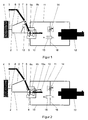
- FIG. 1 is a sketchy representation of a first embodiment of the Wheel suspension according to the invention can be seen.
- a lower wishbone 1 is with his one end pivotally attached to a wheel carrier 3 via a ball joint 2 which the vehicle wheel 4 is arranged.
- an upper wishbone 5 with his one end over a ball joint 6 on the wheel carrier 3 and with its other end over a rubber joint 7 is pivotally mounted on the vehicle body 8.
- the other end of the lower wishbone 1 is connected to the motor shaft 9a of a swivel motor 9, whose housing 9b is attached to the vehicle body 8.
- the swivel motor 9 is via a first hydraulic line 10 and a second Hydraulic line 11 connected to a hydraulic pump 12, of which the hydraulic swivel motor 9 hydraulic fluid can be supplied.
- a hydraulic pump 12 of which the hydraulic swivel motor 9 hydraulic fluid can be supplied.
- the lower control arm 1 together with the Vehicle wheel 4 pivoted toward vehicle body 8 or pivoted away from it become.
- the vehicle spring 13 is according to this embodiment attached at one end to the lower wishbone 1, but it is after one Another embodiment also possible, the vehicle spring 13 with one end to attach the upper wishbone 5.
- FIG. 11 shows a series connection of a hydraulic throttle 14 and a valve 15 provided so that a bypass 16 by opening the valve 15 between the two hydraulic lines 10 and 11 with a via the hydraulic throttle 14 set flow resistance for the hydraulic fluid can be set up can.
- FIG. 2 is a sketchy representation of a second embodiment of the Wheel suspension according to the invention can be seen, wherein for identical or functionally identical features the same reference numerals as in the first Embodiment can be used.
- the lower wishbone 1 has one over its Extension point 13a extending to the vehicle body 8 on which has the vehicle spring 13 at a distance from the motor shaft 9a at one end is attached. Except for the extension 13a of the handlebar 1 and the attachment of the Vehicle spring 13 on this extension 13a agrees with the second embodiment the first embodiment.
- extension 13a By forming the extension 13a on the lower control arm 1, it is possible become, the vehicle spring 13 outside the space between the vehicle body 8 and to arrange the vehicle wheel 4 so that this space for arranging others Motor vehicle components can be used.
- FIG 3 From Figure 3 is a detailed schematic diagram of a regulated vane pump can be seen, the hydraulic pump 12 for the two embodiments according to the Figures 1 and 2 can be used. For reasons of clarity, they are Hydraulic throttle 14, the valve 15 and the secondary line 16 not in this figure shown.
- the hydraulic pump 12 is implemented in the form of a vane pump, one in one Housing 17 rotatably mounted and driven by an electric motor (not shown) Has shaft 18 which is rotatably and liquid-tightly mounted in the housing 17.
- shaft 18 In the Shaft 18 are a plurality of radially outwardly projecting lamellae 19 around their circumference arranged that their radial distance to the center line 18a of the shaft 18 in a for Vane pumps can vary in the usual way.
- the shaft 18 is in one arranged cylindrical and filled with hydraulic fluid pump chamber 20, which is formed in a reciprocating piston 21 arranged in the housing 17, which is vertical to the center line 18a of the shaft 18 in the direction of the arrow P via guide bands or Piston rings 22 is slidably mounted in the housing 17.
- two opposite bushings 21a and 21b (shown in dashed lines) in the piston 21, which extends from the pump chamber 20 through the piston 21 into a first transition chamber 23a or into a second transition chamber 23b extend.
- the two transition chambers 23a and 23b (shown in dashed lines) are in turn via two oppositely running and through the housing 17th extending through bushings 24a and 24b (shown in dashed lines) connected to the hydraulic lines 10 and 11 and lie with respect to the central axis 17a (shown in broken lines) of the housing 17 diametrically opposite one another.
- the one delivered by the hydraulic pump 12 can be Set the amount of hydraulic fluid, in which position of the lifting piston 21, in which the pump chamber 20 is arranged concentrically to the shaft 18, none Hydraulic fluid is pumped.
- the lamellae 19 become radially outward from the shaft 18 pressed out and lie with their ends facing away from the center line 18a of the shaft 18 on the inner wall of the pump chamber 20.
- the Reciprocating piston 21 - and thus also the center line 20a of the pump chamber 20 - opposite the The center line 18a of the shaft 18 is shifted to the left, so that an eccentricity between the Pump chamber 20 and the shaft 18 is formed.
- This eccentricity means that the slats 19 emerge shorter on the right side from the shaft 18 than on the left side, so when rotating the shaft clockwise more Hydraulic fluid is transported out of the lower region of the pump chamber 20 than being transported into it. Therefore, the hydraulic pump 12 delivers in this mode the hydraulic fluid from the first transition chamber 23a through which Pump chamber 20 through and into the second transition chamber 23b. In this In this case, the hydraulic fluid flows from the hydraulic pump 12 through the second Hydraulic line 11 into the hydraulic swivel motor 9, so that this one in Outputs oriented torque to the motor shaft 9a in the sense of the arrow M. Then flows the hydraulic fluid from the hydraulic swing motor 9 through the first Hydraulic line 10 back into hydraulic pump 12.
- the reciprocating piston 21 is displaced such that the center line 20a of the pump chamber 20 to the right of the center line 18a of the shaft 18, this leads to eccentricity of Pump chamber 20 and shaft 18 cause the hydraulic fluid from the second Transition chamber 23b out, through the pump chamber 20 and into the first Transition chamber 23a is conveyed into it.
- the hydraulic fluid flows from the hydraulic pump 12 through the first hydraulic line 10 into the swivel motor 9, so that this torque in the opposite sense of the arrow M to the Motor shaft 9a releases. Then the hydraulic fluid flows from the hydraulic one Swing motor 9 through the second hydraulic line 11 back into the Hydraulic pump 12.
- the electrical coil 27 is a electronic control device (not shown) controlled in such a way that on the actuating piston 26 an actuating force is exerted via the magnetic field generated by the electrical coil 27, which because of the mechanical coupling of the actuating piston 26 with one end face of the Reciprocating piston 21 also acts simultaneously on the reciprocating piston 21.
- the desired setpoint pressure difference can be set via the setpoint generator 25 be by the reciprocating piston 21 in one of the setpoint pressure difference assigned Setpoint position is shifted.
- the frequency with which the piston 21 of the Setpoint generator 25 pushed back and forth between different setpoint positions was around 5 Hz in a test setup.
- the reciprocating piston 21 is with its other end face with the Housing 17 of the hydraulic pump 12 coupled via a mechanical spring 28, which is dimensioned that the pump chamber 20 in the concentric position with the shaft 18 is brought when only the force of the mechanical spring 28 on the Reciprocating piston 21 acts.
- the mechanical spring 28 thus has the function, inter alia, of Reciprocating piston 21 after switching off or the failure of the hydraulic pump 12 in one bring certain position, so when turning on the hydraulic pump 12 defined starting state for the reciprocating piston 21 is present.
- the electrical coil 27 is removed from the controlled electronic control unit such that the setpoint generator 25 one for Maintaining the setpoint pressure difference applies sufficient force.
- the piston 21 can thus be regarded as being mounted between two springs 25 and 28, the of the force emitted by the setpoint generator 25 via the force electronic control unit is adjustable. If there is a fault Displacement of the reciprocating piston 21, the springs 25 and 28 set after this has subsided Fault the piston 21 back to its setpoint position.
- an electric motor can also be used, which has a linear actuator via a transmission drives which is coupled to the reciprocating piston 21 via a mechanical spring.
- a cylindrical one Control piston 29, 30 mechanically coupled, a first of the control piston 29 slidable and liquid-tight in a one-sided closed first hollow cylinder 31 and the second control piston 30 slidably and liquid-tight in a closed on one side engages second hollow cylinder 32.
- the between the control piston 29 and 30 and the Inner wall of the two hollow cylinders 31 and 32 hydraulic chambers are formed each filled with hydraulic fluid and via two hydraulic control lines 33 and 34 with the interposition of two hydraulic throttles 35 and 36 with the first or the second hydraulic line 10, 11, so that with this arrangement hydraulic control is implemented taking into account the current hydraulic Pressure difference between the pressures in the two hydraulic lines 10 and 11 the Setpoint pressure difference maintained.
Applications Claiming Priority (2)
| Application Number | Priority Date | Filing Date | Title |
|---|---|---|---|
| DE10151580 | 2001-10-23 | ||
| DE2001151580 DE10151580A1 (de) | 2001-10-23 | 2001-10-23 | Radaufhängung für ein Kraftfahrzeug |
Publications (3)
| Publication Number | Publication Date |
|---|---|
| EP1306237A2 true EP1306237A2 (fr) | 2003-05-02 |
| EP1306237A3 EP1306237A3 (fr) | 2004-11-17 |
| EP1306237B1 EP1306237B1 (fr) | 2008-04-09 |
Family
ID=7703007
Family Applications (1)
| Application Number | Title | Priority Date | Filing Date |
|---|---|---|---|
| EP20020023591 Expired - Fee Related EP1306237B1 (fr) | 2001-10-23 | 2002-10-23 | Suspension de roue de véhicule automobile |
Country Status (2)
| Country | Link |
|---|---|
| EP (1) | EP1306237B1 (fr) |
| DE (2) | DE10151580A1 (fr) |
Families Citing this family (6)
| Publication number | Priority date | Publication date | Assignee | Title |
|---|---|---|---|---|
| DE10360231A1 (de) * | 2003-12-20 | 2005-07-21 | Zf Lenksysteme Gmbh | Fahrwerkssystem mit aktiver Federung |
| DE102010023985A1 (de) * | 2010-06-16 | 2011-08-04 | Daimler AG, 70327 | Radaufhängung |
| DE202012101878U1 (de) | 2012-05-23 | 2013-08-26 | Asturia Automotive Systems Ag | Anordnung/Lagerung eines aktiven Radführungslenkers |
| DE102013004956B4 (de) | 2013-03-22 | 2016-07-28 | Audi Ag | Rotationsdämpfer |
| DE102014216877A1 (de) * | 2014-08-25 | 2016-02-25 | Bayerische Motoren Werke Aktiengesellschaft | Fahrwerk eines Kraftfahrzeugs mit Rotationsdämpfer |
| DE102017202550A1 (de) | 2017-02-16 | 2018-08-16 | Audi Ag | Radaufhängung |
Citations (1)
| Publication number | Priority date | Publication date | Assignee | Title |
|---|---|---|---|---|
| DE1175563B (de) | 1959-10-31 | 1964-08-06 | Daimler Benz Ag | Vorrichtung zur Kurvenstabilisierung des Wagenkastens bei Kraftfahrzeugen |
Family Cites Families (7)
| Publication number | Priority date | Publication date | Assignee | Title |
|---|---|---|---|---|
| US4531898A (en) * | 1983-12-13 | 1985-07-30 | Nissan Motor Co., Ltd. | Control system for a vane type variable displacement pump |
| DE3937986A1 (de) * | 1989-11-15 | 1991-05-16 | Bosch Gmbh Robert | Fahrzeugfederung ii |
| WO1991011339A2 (fr) * | 1990-02-02 | 1991-08-08 | The University Of British Columbia | Systeme numerique de suspension |
| JPH03239619A (ja) * | 1990-02-16 | 1991-10-25 | Kayaba Ind Co Ltd | 油圧サスペンション装置 |
| JPH04159112A (ja) * | 1990-10-19 | 1992-06-02 | Kayaba Ind Co Ltd | サスペンション |
| JPH11208234A (ja) * | 1998-01-30 | 1999-08-03 | Unisia Jecs Corp | ロータリダンパ |
| DE10043711B4 (de) * | 2000-09-04 | 2006-01-26 | Sachsenring Zwickau Ag | Aktuator zur aktiven Fahrwerksregelung |
-
2001
- 2001-10-23 DE DE2001151580 patent/DE10151580A1/de not_active Withdrawn
-
2002
- 2002-10-23 DE DE50212056T patent/DE50212056D1/de not_active Expired - Fee Related
- 2002-10-23 EP EP20020023591 patent/EP1306237B1/fr not_active Expired - Fee Related
Patent Citations (1)
| Publication number | Priority date | Publication date | Assignee | Title |
|---|---|---|---|---|
| DE1175563B (de) | 1959-10-31 | 1964-08-06 | Daimler Benz Ag | Vorrichtung zur Kurvenstabilisierung des Wagenkastens bei Kraftfahrzeugen |
Also Published As
| Publication number | Publication date |
|---|---|
| DE50212056D1 (de) | 2008-05-21 |
| EP1306237B1 (fr) | 2008-04-09 |
| DE10151580A1 (de) | 2003-04-30 |
| EP1306237A3 (fr) | 2004-11-17 |
Similar Documents
| Publication | Publication Date | Title |
|---|---|---|
| DE102004058698B3 (de) | Radaufhängung mit Federverstellung für Kraftfahrzeuge | |
| DE102006002983B4 (de) | Aktives Fahrwerksystem eines Fahrzeugs | |
| DE60226122T2 (de) | Aufhängungsanordnung | |
| DE102012107301B4 (de) | Aktives wankstabilisierungssystem | |
| DE10120102A1 (de) | Aktives Fahrwerk mit elektrischem Aktuator und Dämpfer | |
| DE3536867C2 (de) | Federbein für eine Fahrzeugradaufhängung | |
| DE2360149A1 (de) | Aufhaenge-einrichtung zur berichtigung der karosserie-lage an kraftwagen | |
| EP3414456B1 (fr) | Machine à pistons alternatifs, notamment compresseur à pistons alternatifs à au moins deux étages, dispositif d'alimentation en air comprimé, système d'alimentation en air comprimé et véhicle, notamment voiture particulière équipée d'un dispositif d'alimentation en air comprimé | |
| DE102006061985B4 (de) | Radaufhängung für ein Kraftfahrzeug | |
| EP3586033A1 (fr) | Élément de liaison au sol pourvu d'un amortisseur rotatif | |
| DE102009047128A1 (de) | Fahrwerk für ein Fahrzeug | |
| DE102005043176A1 (de) | Fahrzeug | |
| DE102012108552B4 (de) | Aktives wankstabilisierungssystem | |
| DE102009056105A1 (de) | Wankstabilisierungssystem für ein Fahrzeug | |
| DE10242724B4 (de) | Antriebseinheit für einen Kraftfahrzeugachsstabilisator | |
| EP1306237A2 (fr) | Suspension de roue de véhicule automobile | |
| DE3517624C2 (fr) | ||
| DE102005048916A1 (de) | Stabilisator mit einer magnetorheologischen Kopplungseinrichtung | |
| DE3123243A1 (de) | Steuerventilanordnung fuer kraftfahrzeug-bremseinrichtungen | |
| DE3925241A1 (de) | Vorrichtung zur radstellungsaenderung von kraftfahrzeugen | |
| DE3409154C2 (fr) | ||
| EP1369267B1 (fr) | Jambe de suspension hydraulique avec guidage | |
| DE3442622A1 (de) | Luftfedervorrichtung | |
| DE102016226013A1 (de) | Drehfederstabsystem einer Achse eines zweispurigen Kraftfahrzeugs | |
| DE3734697A1 (de) | Federungssystem fuer kraftfahrzeuge mit schwenkbar am fahrzeugaufbau angelenkten radfuehrungsgliedern |
Legal Events
| Date | Code | Title | Description |
|---|---|---|---|
| PUAI | Public reference made under article 153(3) epc to a published international application that has entered the european phase |
Free format text: ORIGINAL CODE: 0009012 |
|
| AK | Designated contracting states |
Designated state(s): AT BE BG CH CY CZ DE DK EE ES FI FR GB GR IE IT LI LU MC NL PT SE SK TR |
|
| AX | Request for extension of the european patent |
Extension state: AL LT LV MK RO SI |
|
| PUAL | Search report despatched |
Free format text: ORIGINAL CODE: 0009013 |
|
| AK | Designated contracting states |
Kind code of ref document: A3 Designated state(s): AT BE BG CH CY CZ DE DK EE ES FI FR GB GR IE IT LI LU MC NL PT SE SK TR |
|
| AX | Request for extension of the european patent |
Extension state: AL LT LV MK RO SI |
|
| 17P | Request for examination filed |
Effective date: 20041202 |
|
| 17Q | First examination report despatched |
Effective date: 20050504 |
|
| AKX | Designation fees paid |
Designated state(s): DE ES FR GB IT SE |
|
| GRAP | Despatch of communication of intention to grant a patent |
Free format text: ORIGINAL CODE: EPIDOSNIGR1 |
|
| GRAS | Grant fee paid |
Free format text: ORIGINAL CODE: EPIDOSNIGR3 |
|
| GRAA | (expected) grant |
Free format text: ORIGINAL CODE: 0009210 |
|
| AK | Designated contracting states |
Kind code of ref document: B1 Designated state(s): DE ES FR GB IT SE |
|
| REG | Reference to a national code |
Ref country code: GB Ref legal event code: FG4D Free format text: NOT ENGLISH |
|
| REF | Corresponds to: |
Ref document number: 50212056 Country of ref document: DE Date of ref document: 20080521 Kind code of ref document: P |
|
| PG25 | Lapsed in a contracting state [announced via postgrant information from national office to epo] |
Ref country code: ES Free format text: LAPSE BECAUSE OF FAILURE TO SUBMIT A TRANSLATION OF THE DESCRIPTION OR TO PAY THE FEE WITHIN THE PRESCRIBED TIME-LIMIT Effective date: 20080720 |
|
| EN | Fr: translation not filed | ||
| PG25 | Lapsed in a contracting state [announced via postgrant information from national office to epo] |
Ref country code: SE Free format text: LAPSE BECAUSE OF FAILURE TO SUBMIT A TRANSLATION OF THE DESCRIPTION OR TO PAY THE FEE WITHIN THE PRESCRIBED TIME-LIMIT Effective date: 20080709 |
|
| PGFP | Annual fee paid to national office [announced via postgrant information from national office to epo] |
Ref country code: DE Payment date: 20081016 Year of fee payment: 7 |
|
| PLBE | No opposition filed within time limit |
Free format text: ORIGINAL CODE: 0009261 |
|
| STAA | Information on the status of an ep patent application or granted ep patent |
Free format text: STATUS: NO OPPOSITION FILED WITHIN TIME LIMIT |
|
| 26N | No opposition filed |
Effective date: 20090112 |
|
| PG25 | Lapsed in a contracting state [announced via postgrant information from national office to epo] |
Ref country code: FR Free format text: LAPSE BECAUSE OF FAILURE TO SUBMIT A TRANSLATION OF THE DESCRIPTION OR TO PAY THE FEE WITHIN THE PRESCRIBED TIME-LIMIT Effective date: 20090130 |
|
| GBPC | Gb: european patent ceased through non-payment of renewal fee |
Effective date: 20081023 |
|
| PG25 | Lapsed in a contracting state [announced via postgrant information from national office to epo] |
Ref country code: IT Free format text: LAPSE BECAUSE OF FAILURE TO SUBMIT A TRANSLATION OF THE DESCRIPTION OR TO PAY THE FEE WITHIN THE PRESCRIBED TIME-LIMIT Effective date: 20080409 |
|
| PG25 | Lapsed in a contracting state [announced via postgrant information from national office to epo] |
Ref country code: GB Free format text: LAPSE BECAUSE OF NON-PAYMENT OF DUE FEES Effective date: 20081023 |
|
| PG25 | Lapsed in a contracting state [announced via postgrant information from national office to epo] |
Ref country code: DE Free format text: LAPSE BECAUSE OF NON-PAYMENT OF DUE FEES Effective date: 20100501 |