EP1306237B1 - Suspension de roue de véhicule automobile - Google Patents
Suspension de roue de véhicule automobile Download PDFInfo
- Publication number
- EP1306237B1 EP1306237B1 EP20020023591 EP02023591A EP1306237B1 EP 1306237 B1 EP1306237 B1 EP 1306237B1 EP 20020023591 EP20020023591 EP 20020023591 EP 02023591 A EP02023591 A EP 02023591A EP 1306237 B1 EP1306237 B1 EP 1306237B1
- Authority
- EP
- European Patent Office
- Prior art keywords
- vehicle
- hydraulic
- wheel
- motor
- vehicle body
- Prior art date
- Legal status (The legal status is an assumption and is not a legal conclusion. Google has not performed a legal analysis and makes no representation as to the accuracy of the status listed.)
- Expired - Fee Related
Links
Images
Classifications
-
- B—PERFORMING OPERATIONS; TRANSPORTING
- B60—VEHICLES IN GENERAL
- B60G—VEHICLE SUSPENSION ARRANGEMENTS
- B60G7/00—Pivoted suspension arms; Accessories thereof
- B60G7/02—Attaching arms to sprung part of vehicle
-
- B—PERFORMING OPERATIONS; TRANSPORTING
- B60—VEHICLES IN GENERAL
- B60G—VEHICLE SUSPENSION ARRANGEMENTS
- B60G13/00—Resilient suspensions characterised by arrangement, location or type of vibration dampers
- B60G13/001—Arrangements for attachment of dampers
-
- B—PERFORMING OPERATIONS; TRANSPORTING
- B60—VEHICLES IN GENERAL
- B60G—VEHICLE SUSPENSION ARRANGEMENTS
- B60G17/00—Resilient suspensions having means for adjusting the spring or vibration-damper characteristics, for regulating the distance between a supporting surface and a sprung part of vehicle or for locking suspension during use to meet varying vehicular or surface conditions, e.g. due to speed or load
- B60G17/015—Resilient suspensions having means for adjusting the spring or vibration-damper characteristics, for regulating the distance between a supporting surface and a sprung part of vehicle or for locking suspension during use to meet varying vehicular or surface conditions, e.g. due to speed or load the regulating means comprising electric or electronic elements
- B60G17/0152—Resilient suspensions having means for adjusting the spring or vibration-damper characteristics, for regulating the distance between a supporting surface and a sprung part of vehicle or for locking suspension during use to meet varying vehicular or surface conditions, e.g. due to speed or load the regulating means comprising electric or electronic elements characterised by the action on a particular type of suspension unit
-
- B—PERFORMING OPERATIONS; TRANSPORTING
- B60—VEHICLES IN GENERAL
- B60G—VEHICLE SUSPENSION ARRANGEMENTS
- B60G2200/00—Indexing codes relating to suspension types
- B60G2200/10—Independent suspensions
- B60G2200/14—Independent suspensions with lateral arms
- B60G2200/144—Independent suspensions with lateral arms with two lateral arms forming a parallelogram
-
- B—PERFORMING OPERATIONS; TRANSPORTING
- B60—VEHICLES IN GENERAL
- B60G—VEHICLE SUSPENSION ARRANGEMENTS
- B60G2202/00—Indexing codes relating to the type of spring, damper or actuator
- B60G2202/20—Type of damper
- B60G2202/22—Rotary Damper
-
- B—PERFORMING OPERATIONS; TRANSPORTING
- B60—VEHICLES IN GENERAL
- B60G—VEHICLE SUSPENSION ARRANGEMENTS
- B60G2202/00—Indexing codes relating to the type of spring, damper or actuator
- B60G2202/40—Type of actuator
- B60G2202/41—Fluid actuator
- B60G2202/413—Hydraulic actuator
-
- B—PERFORMING OPERATIONS; TRANSPORTING
- B60—VEHICLES IN GENERAL
- B60G—VEHICLE SUSPENSION ARRANGEMENTS
- B60G2202/00—Indexing codes relating to the type of spring, damper or actuator
- B60G2202/40—Type of actuator
- B60G2202/41—Fluid actuator
- B60G2202/414—Fluid actuator using electrohydraulic valves
-
- B—PERFORMING OPERATIONS; TRANSPORTING
- B60—VEHICLES IN GENERAL
- B60G—VEHICLE SUSPENSION ARRANGEMENTS
- B60G2202/00—Indexing codes relating to the type of spring, damper or actuator
- B60G2202/40—Type of actuator
- B60G2202/41—Fluid actuator
- B60G2202/416—Fluid actuator using a pump, e.g. in the line connecting the lower chamber to the upper chamber of the actuator
-
- B—PERFORMING OPERATIONS; TRANSPORTING
- B60—VEHICLES IN GENERAL
- B60G—VEHICLE SUSPENSION ARRANGEMENTS
- B60G2202/00—Indexing codes relating to the type of spring, damper or actuator
- B60G2202/40—Type of actuator
- B60G2202/442—Rotary actuator
Definitions
- the invention relates to a suspension for a motor vehicle according to the preamble of claim 1.
- Wheel suspensions in which the handlebar is attached, for example, via a ball joint to a wheel carrier accommodating the vehicle wheel and to the vehicle body via a rubber mount, are known from the prior art. Between the handlebar and the vehicle body further a shock absorber and a vehicle spring are arranged, of which the vehicle body is kept at a distance from the vehicle wheel. The ride comfort is significantly dependent on the spring characteristic of the vehicle spring and the damping behavior of the shock absorber.
- a stabilizer between the two vehicle wheels of an axle of the motor vehicle may additionally be arranged.
- a torsion spring rod is used as a stabilizer, which is connected at one end via a first pendulum support with a first of the two vehicle wheels and at its other end via a second pendulum support to the second vehicle, wherein the middle part of the stabilizer lying between the two ends Vehicle body is stored.
- the pendulum supports can be fastened with their ends facing away from the stabilizer on the wheel carriers receiving the wheels or on the links connecting the wheel carriers to the vehicle body.
- the generic JP 3-239619 A has a suspension for a motor vehicle with a arranged between a vehicle and the vehicle body arm, which is pivotally connected at one end to the vehicle and at the other end pivotally connected to the vehicle body, on, wherein the link is connected via a pivot motor to the vehicle body and pivotable about the pivot axis of the pivot motor.
- WO 91/11339 A shows in FIG. 3 also a wheel suspension according to the preamble of claim 1.
- JP 4-159112 A discloses a suspension in which a handlebar is pivotally connected to a rotational damper with the vehicle body and with a wheel.
- the handlebar has an extension, which was designed as a leaf spring.
- This spring is attached according to the disclosure of the Scriptures in the fulcrum of the handlebars. Consequently, this spring is not attached to an extension of the handlebar, but forms even this extension.
- the object of the invention is to provide a suspension for a motor vehicle, in which the properties of the connection of the vehicle wheel to the vehicle body can be influenced separately and actively and ride comfort is improved overall.
- the handlebar is connected via a pivot motor with the vehicle body and pivotable about the pivot axis of the swing motor. Since the handlebar is fastened with its end facing away from the swivel motor to the vehicle wheel, the distance between the vehicle wheel and the vehicle body can be adjusted via the actuation of the swivel motor. Furthermore, both the suspension behavior and the damping behavior of the vehicle wheel relative to the vehicle body can be controlled via the swivel motor, so that the properties of the connection of the vehicle wheel to the vehicle body can be influenced separately and actively.
- the shock absorber used regularly in motor vehicles can be omitted, the task of which is now perceptible by the swing motor of the suspension according to the invention.
- the pivot motor can be dispensed with a vehicle spring, when the pivot motor during use of the motor vehicle maintains a sufficient distance between the vehicle and the vehicle body.
- a vehicle spring is arranged, which is directly or indirectly connected at one end to the vehicle and at the other end to the vehicle body.
- one end of the vehicle spring may also be fastened to a chassis component which connects the vehicle wheel to the vehicle body, wherein the vehicle spring is fastened with its one end at a distance to the pivot motor or to the vehicle body on the handlebar.
- the vehicle spring is fastened with its one end to the handlebar, it can extend far into the space between the vehicle wheel and the vehicle body.
- this space area is often provided for other components in the motor vehicle, so that the handlebar has an extension beyond its connection point to the pivot motor or the vehicle body extension, to which the vehicle spring is attached with its one end.
- the vehicle spring it is possible to arrange the vehicle spring in only a small area within or even completely outside this space area.
- the swivel motor can be connected directly to the handlebar and / or the vehicle body according to an embodiment of the invention.
- a mechanical damping element is arranged between the swivel motor and the link and / or between the swivel motor and the vehicle body, which transmits jerky movements emanating from the swivel motor to the driver and / or the vehicle body, whereby the ride comfort is increased.
- the vehicle spring may be an elastomer spring or a steel spring, for example in the form of a helical spring, which has a nearly identical behavior with respect to their spring characteristic under static and dynamic load.
- the vehicle spring is an air spring which has a spring characteristic which can be varied via the air pressure and differences in its dynamic and static behavior, so that the spring behavior of the wheel suspension can be adapted to different driving situations in a desired manner without having to replace the vehicle spring itself ,
- the swivel motor can be operated electrically or pneumatically.
- the swivel motor is operated hydraulically and is connected via hydraulic lines with a regulated hydraulic pump, since a hydraulically operated swivel motor can be regularly controlled faster than a purely pneumatically operated swivel motor, in which the great compressibility of the air of rapid controllability counteracts.
- the problem arises in the motor vehicle of the electric power supply. A sudden increase in load can be associated with a large electrical power requirement, which can often not be covered due to the motor vehicle battery used with a voltage of 12V or 24V.
- the hydraulic pump can be designed, for example, in the form of a gear pump.
- the hydraulic pump is an electrically driven vane-cell pump, since it can be switched back and forth more quickly between different hydraulic pressure stages.
- the hydraulic pump can be controlled mechanically, electrically or pneumatically.
- the hydraulic pump has a hydraulic control device connected to the hydraulic lines for maintaining a predetermined hydraulic pressure difference (setpoint) between the pressures in the hydraulic lines, since a hydraulic control can be implemented very close to the system and, for example, without the conversion from mechanical to electrical variables.
- the predetermined hydraulic pressure difference between the pressures in the hydraulic lines may be unchangeable.
- an electrically controlled setpoint generator for setting the predetermined hydraulic pressure difference. This takes into account that, for example, depending on the load condition of the motor vehicle, a different setpoint for the hydraulic control device can be set.
- an electrically controlled setpoint generator instead of an electrically controlled setpoint generator, however, a mechanically, pneumatically or hydraulically controlled setpoint generator can be used.
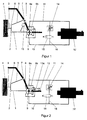
- FIG. 1 is a sketchy representation of an embodiment of a non-inventive suspension visible.
- a lower wishbone 1 is pivotally attached at one end via a ball joint 2 to a wheel carrier 3, on which the vehicle wheel 4 is arranged.
- an upper wishbone 5 is pivotally mounted with its one end via a ball joint 6 on the wheel carrier 3 and with its other end via a rubber hinge 7 on the vehicle body 8.
- the other end of the lower arm 1 is connected to the motor shaft 9 a of a swing motor 9, the housing 9 b is fixed to the vehicle body 8.
- the swing motor 9 is connected via a first hydraulic line 10 and via a second hydraulic line 11 to a hydraulic pump 12, from which the hydraulic swing motor 9 hydraulic fluid can be supplied. Depending on whether the hydraulic fluid flows through the hydraulic line 10 or through the hydraulic line 11 in the pivot motor 9, the lower arm 1 can be pivoted together with the vehicle 4 to the vehicle body 8 and pivoted away from it.
- vehicle spring 13 For Aufnahe of at least a portion of the force exerted by the vehicle body 8 on the vehicle 4 load between the lower arm 1 and the vehicle body 8 designed as an air spring vehicle spring 13 is arranged with its one end at a distance from the motor shaft 9a on the lower arm 1 and with its other end is fixed to the vehicle body 8 and thus relieves the swing motor 9 in maintaining the distance between the vehicle wheel 4 and the vehicle body 8.
- the vehicle spring 13 is attached according to this embodiment with its one end to the lower arm 1, but according to another embodiment, it is also possible to fasten the vehicle spring 13 with its one end to the upper arm 5.
- FIG. 2 is a sketchy representation of an embodiment of the suspension according to the invention can be seen, for identical or functionally identical features the same reference numerals as in the first embodiment are used.
- the lower wishbone 1 has a beyond its point of articulation to the vehicle body 8 extending beyond extension 13a, on which the vehicle spring 13 is fixed at a distance from the motor shaft 9a with its one end. Except for the extension 13a of the handlebar 1 and the attachment of the vehicle spring 13 to this extension 13a, the embodiment of the present invention coincides with the embodiment not according to the invention.
- extension 13a By forming the extension 13a on the lower arm 1, it has become possible to arrange the vehicle spring 13 outside the space between the vehicle body 8 and the vehicle wheel 4, so that this space can be used for arranging other automobile components.
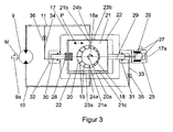
- FIG. 3 is a detailed schematic diagram of a controlled vane pump can be seen as the hydraulic pump 12 for the two embodiments according to the Figures 1 and 2 can be used.
- the hydraulic throttle 14, the valve 15 and the secondary line 16 are not shown in this figure.
- the hydraulic pump 12 is realized in the form of a vane pump, which has a shaft 18 which is rotatably mounted in a housing 17 and driven by an electric motor (not shown), which shaft is rotatably and fluid-tightly mounted in the housing 17.
- a plurality of radially outwardly projecting fins 19 are arranged around its circumference, which can vary their radial distance from the center line 18a of the shaft 18 in a usual manner for vane pumps manner.
- the shaft 18 is arranged in a cylindrical and filled with hydraulic fluid pump chamber 20 which is formed in a arranged in the housing 17 reciprocating piston 21 which is perpendicular to the center line 18 a of the shaft 18 in the direction of arrow P via guide bands or piston rings 22 in the housing 17 is slidably mounted.
- Perpendicular to the central axis 18a of the shaft 18 and perpendicular to the direction of movement P are two oppositely extending passages 21a and 21b (shown in phantom) formed in the reciprocating piston 21 extending from the pump chamber 20 through the reciprocating piston 21 into a first transition chamber 23a and in a second transition chamber 23b extend.
- the two transition chambers 23a and 23b (shown in dashed lines) are in turn connected to the hydraulic lines 10 and 11 via two oppositely extending and extending through the housing 17 additional passages 24a and 24b (shown in phantom) and lie with respect to the central axis 17a (shown in phantom) of the housing 17 diametrically opposite each other.
- one is Connection of the pump chamber 20 via the first transition chamber 23 a with the first hydraulic line 10 and a connection of the pump chamber 20 via the second transition chamber 23 b with the second hydraulic line 11 with the interposition of the passages 21 a, 21 b, 24 a and 24 b created.
- the two transition chambers 23a and 23b are formed according to this embodiment in the inner wall of the housing 17, but they can be provided according to another embodiment, in the lateral surface of the piston 21.
- the amount of hydraulic fluid delivered by the hydraulic pump 12 can be adjusted, wherein in that position of the piston 21, in which the pump chamber 20 is arranged concentrically to the shaft 18, no hydraulic fluid is conveyed.
- the lamellae 19 Due to the centrifugal force or due to the spring force of arranged in the shaft 18 springs (not shown), the lamellae 19 are pushed radially outwardly from the shaft 18 and lie with their the center line 18a of the shaft 18 opposite ends on the inner wall of the pump chamber 20 at. How out FIG. 3 can be seen, the reciprocating piston 21- and thus the center line 20a of the pump chamber 20 - relative to the center line 18a of the shaft 18 is shifted to the left, so that an eccentricity between the pump chamber 20 and the shaft 18 is formed.
- the displacement of the lifting piston 21 in the housing 17 along the center line 17a it is thus possible to set in which direction and at which throughput the hydraulic fluid is conveyed by the hydraulic pump 12.
- this also simultaneously sets the pressure difference between the pressures in the two hydraulic lines 10 and 11, which determines the torque output by the motor 9 via the motor shaft 9a, via which the pivot angle of the lower arm 1 and thus also the distance of the vehicle wheel 4 from Vehicle body 8 is adjustable.
- the two chambers formed between the end faces of the lifting piston 21 and the housing 17 are connected to one another via at least one compensating groove 21c formed in the lateral surface of the lifting piston 21, through which hydraulic fluid can be exchanged between the two chambers during displacement of the lifting piston 21.
- According to another embodiment may be provided in the housing 17 or a bore in the reciprocating piston 21 instead of or in addition to the Kompensationsnut 21c also connecting these chambers.
- a predetermined hydraulic torque difference between the pressures in the two hydraulic lines 10 and 11 is set as a setpoint pressure difference via a setpoint generator 25, the one Has mechanically with one of the two end faces of the reciprocating piston 21 coupled and made of magnetic material actuator piston 26 which is slidably disposed in an electric coil 27.
- the electric coil 27 is controlled via an electronic control unit (not shown) such that on the adjusting piston 26 via the magnetic field generated by the electric coil 27, a force is exerted because of the mechanical coupling of the actuating piston 26 with the one end face of the reciprocating piston 21st also acts simultaneously on the reciprocating piston 21.
- the desired setpoint pressure difference can be adjusted by the reciprocating piston 21 is shifted to a setpoint pressure difference assigned setpoint position .
- the frequency with which the reciprocating piston 21 can be moved back and forth between the nominal value transmitter 25 and different setpoint positions was approximately 5 Hz in a test setup.
- the reciprocating piston 21 is coupled with its other end face to the housing 17 of the hydraulic pump 12 via a mechanical spring 28 which is dimensioned such that the pump chamber 20 is brought into the concentric position with the shaft 18, if only the force of the mechanical Spring 28 acts on the reciprocating piston 21.
- the mechanical spring 28 thus has inter alia the function to bring the reciprocating piston 21 after switching off or failure of the hydraulic pump 12 in a certain position so that when switching on the hydraulic pump 12, a defined starting state for the reciprocating piston 21 is present.
- the electric coil 27 is controlled by the electronic control unit such that the setpoint generator 25 applies sufficient to maintain the setpoint pressure difference.
- the reciprocating piston 21 can thus be considered to be mounted between two springs 25 and 28, wherein the force output by the spring formed by the setpoint generator 25 via the electronic control unit is adjustable. Is it due to a fault to one Displacement of the reciprocating piston 21, so the springs 25 and 28 after decay of this disorder the reciprocating piston 21 back to its setpoint position.
- an electric motor is used, which drives a linear actuator via a transmission, which is coupled via a mechanical spring with the reciprocating piston 21.
- a cylindrical control piston 29, 30 is mechanically coupled, wherein a first of the control piston 29 slidably and liquid-tightly engages in a closed on one side first hollow cylinder 31 and the second control piston 30 slidably and liquid-tight in a closed second hollow cylinder 32 ,
- the hydraulic chambers formed between the control piston 29 and 30 and the inner wall of the two hollow cylinders 31 and 32 are each filled with hydraulic fluid and via two hydraulic control lines 33 and 34 with the interposition of two hydraulic throttles 35 and 36 with the first and the second hydraulic line 10, 11 connected, so that with this arrangement, a hydraulic control is realized, which maintains the setpoint pressure difference taking into account the current hydraulic pressure difference between the pressures in the two hydraulic lines 10 and 11.
Claims (7)
- Suspension de roue pour un véhicule automobile avec un bras de contrôle (1) disposé entre une roue de véhicule (4) et la carrosserie de véhicule (8), qui est relié, par l'une de ses extrémités, de manière à pouvoir pivoter, à la roue de véhicule (4) et, par son autre extrémité, de manière à pouvoir pivoter avec la carrosserie de véhicule (8), le bras de contrôle (1) étant relié par un moteur de pivotement (9) à la carrosserie de véhicule (8) et pouvant pivoter autour de l'axe de pivotement du moteur de pivotement (9),
caractérisée en ce que
entre la roue de véhicule (4) et la carrosserie de véhicule (8) est disposé un ressort de véhicule (13) qui est relié directement ou indirectement, par l'une de ses extrémités, à la roue de véhicule (4) et, par son autre extrémité, à la carrosserie de véhicule (8), et est fixé, par l'une de ses extrémités, à distance du moteur de pivotement (9), au bras de contrôle (1), le bras de contrôle (1) présentant un prolongement (13a) s'étendant au-delà de son attache au moteur de pivotement (9), prolongement auquel le ressort de véhicule (13) est fixé par l'une de ses extrémités. - Suspension de roue selon la revendication 1, caractérisée en ce qu'entre le moteur de pivotement (9) et le bras de contrôle (1) et/ou entre le moteur de pivotement (9) et la carrosserie de véhicule (8) est disposé un élément d'amortissement mécanique.
- Suspension de roue selon l'une quelconque des revendications 1 ou 2, caractérisée en ce que le ressort de véhicule (13) est un ressort pneumatique.
- Suspension de roue selon l'une quelconque des revendications 1 à 3, caractérisée en ce que le moteur de pivotement (9) fonctionne de manière hydraulique et est relié, par des conduites hydrauliques (10, 11), à une pompe hydraulique (12) régulée.
- Suspension de roue selon la revendication 4, caractérisée en ce que la pompe hydraulique (12) est une pompe à cellules semi-rotatives fonctionnant électriquement.
- Suspension de roue selon la revendication 4 ou 5, caractérisée en ce que la pompe hydraulique (12) comporte un dispositif de régulation hydraulique (29, 30, 31, 32, 33, 34, 35, 36) relié aux conduites hydrauliques (10, 11), pour maintenir une différence de pression hydraulique prédéterminée entre les pressions à l'intérieur des conduites hydrauliques (10, 11).
- Suspension de roue selon la revendication 6, caractérisée en ce qu'un transmetteur de valeurs de consigne (25), commandé électriquement, est accouplé à la pompe hydraulique (12) pour régler la différence de pression hydraulique prédéterminée.
Applications Claiming Priority (2)
| Application Number | Priority Date | Filing Date | Title |
|---|---|---|---|
| DE10151580 | 2001-10-23 | ||
| DE2001151580 DE10151580A1 (de) | 2001-10-23 | 2001-10-23 | Radaufhängung für ein Kraftfahrzeug |
Publications (3)
| Publication Number | Publication Date |
|---|---|
| EP1306237A2 EP1306237A2 (fr) | 2003-05-02 |
| EP1306237A3 EP1306237A3 (fr) | 2004-11-17 |
| EP1306237B1 true EP1306237B1 (fr) | 2008-04-09 |
Family
ID=7703007
Family Applications (1)
| Application Number | Title | Priority Date | Filing Date |
|---|---|---|---|
| EP20020023591 Expired - Fee Related EP1306237B1 (fr) | 2001-10-23 | 2002-10-23 | Suspension de roue de véhicule automobile |
Country Status (2)
| Country | Link |
|---|---|
| EP (1) | EP1306237B1 (fr) |
| DE (2) | DE10151580A1 (fr) |
Cited By (1)
| Publication number | Priority date | Publication date | Assignee | Title |
|---|---|---|---|---|
| DE202012101878U1 (de) | 2012-05-23 | 2013-08-26 | Asturia Automotive Systems Ag | Anordnung/Lagerung eines aktiven Radführungslenkers |
Families Citing this family (5)
| Publication number | Priority date | Publication date | Assignee | Title |
|---|---|---|---|---|
| DE10360231A1 (de) * | 2003-12-20 | 2005-07-21 | Zf Lenksysteme Gmbh | Fahrwerkssystem mit aktiver Federung |
| DE102010023985A1 (de) * | 2010-06-16 | 2011-08-04 | Daimler AG, 70327 | Radaufhängung |
| DE102013004956B4 (de) | 2013-03-22 | 2016-07-28 | Audi Ag | Rotationsdämpfer |
| DE102014216877A1 (de) * | 2014-08-25 | 2016-02-25 | Bayerische Motoren Werke Aktiengesellschaft | Fahrwerk eines Kraftfahrzeugs mit Rotationsdämpfer |
| DE102017202550A1 (de) | 2017-02-16 | 2018-08-16 | Audi Ag | Radaufhängung |
Family Cites Families (8)
| Publication number | Priority date | Publication date | Assignee | Title |
|---|---|---|---|---|
| DE1105290B (de) | 1959-10-31 | 1961-04-20 | Daimler Benz Ag | Vorrichtung zur Kurvenstabilisierung des Wagenkastens bei Kraftfahrzeugen, insbesondere solchen mit Luftfederung |
| US4531898A (en) * | 1983-12-13 | 1985-07-30 | Nissan Motor Co., Ltd. | Control system for a vane type variable displacement pump |
| DE3937986A1 (de) * | 1989-11-15 | 1991-05-16 | Bosch Gmbh Robert | Fahrzeugfederung ii |
| WO1991011339A2 (fr) * | 1990-02-02 | 1991-08-08 | The University Of British Columbia | Systeme numerique de suspension |
| JPH03239619A (ja) * | 1990-02-16 | 1991-10-25 | Kayaba Ind Co Ltd | 油圧サスペンション装置 |
| JPH04159112A (ja) * | 1990-10-19 | 1992-06-02 | Kayaba Ind Co Ltd | サスペンション |
| JPH11208234A (ja) * | 1998-01-30 | 1999-08-03 | Unisia Jecs Corp | ロータリダンパ |
| DE10043711B4 (de) * | 2000-09-04 | 2006-01-26 | Sachsenring Zwickau Ag | Aktuator zur aktiven Fahrwerksregelung |
-
2001
- 2001-10-23 DE DE2001151580 patent/DE10151580A1/de not_active Withdrawn
-
2002
- 2002-10-23 DE DE50212056T patent/DE50212056D1/de not_active Expired - Fee Related
- 2002-10-23 EP EP20020023591 patent/EP1306237B1/fr not_active Expired - Fee Related
Cited By (1)
| Publication number | Priority date | Publication date | Assignee | Title |
|---|---|---|---|---|
| DE202012101878U1 (de) | 2012-05-23 | 2013-08-26 | Asturia Automotive Systems Ag | Anordnung/Lagerung eines aktiven Radführungslenkers |
Also Published As
| Publication number | Publication date |
|---|---|
| DE50212056D1 (de) | 2008-05-21 |
| DE10151580A1 (de) | 2003-04-30 |
| EP1306237A2 (fr) | 2003-05-02 |
| EP1306237A3 (fr) | 2004-11-17 |
Similar Documents
| Publication | Publication Date | Title |
|---|---|---|
| DE60225260T2 (de) | Rollregelungssystem eines fahrzeugs | |
| DE19637159B4 (de) | Radaufhängung mit selbsttätiger Sturzanpassung | |
| EP0426995B1 (fr) | Système de suspension hydropneumatique | |
| EP1175307B1 (fr) | Systeme de stabilisation hydraulique | |
| DE4136262C2 (de) | Fahrwerk eines Kraftfahrzeuges | |
| EP1861269A1 (fr) | Actionneur destine a un stabilisateur segmente d'un vehicule | |
| WO1998002322A1 (fr) | Dispositif antiroulis d'un vehicule | |
| DE102006040109A1 (de) | Aktiver, geteilter Kraftfahrzeugstabilisator mit eingebauten Schwenkmotor | |
| WO2000071371A1 (fr) | Stabilisateur pour vehicule automobile | |
| EP1935680A1 (fr) | Suspension de roue pour un véhicule automobile | |
| DE102006051682A1 (de) | Anordnung zur Fahrwerksstabilisierung | |
| WO2007033718A1 (fr) | Ensemble stabilisateur d'un vehicule automobile | |
| DE102005043176A1 (de) | Fahrzeug | |
| EP3652002A2 (fr) | Sous-ensemble essieu pour poids-lourd, poids-lourd équipé d'au moins un tel sous-ensemble essieu et arrangement hydraulique, notamment destiné à positionner une unité positionnable réalisée sous la forme d'un arrangement de piston et cylindre | |
| EP1263617A1 (fr) | Stabilisateur en deux pieces a raideur optimisee | |
| EP1935677A1 (fr) | Suspension de roue pour un véhicule automobile | |
| DE3744069A1 (de) | Fahrzeugaufhaengung | |
| EP1306237B1 (fr) | Suspension de roue de véhicule automobile | |
| DE102009056105A1 (de) | Wankstabilisierungssystem für ein Fahrzeug | |
| DE10242724B4 (de) | Antriebseinheit für einen Kraftfahrzeugachsstabilisator | |
| EP1020342A2 (fr) | Système de direction avec volant de direction réglable axialement | |
| EP1794009B1 (fr) | Stabilisateur commutable destine a un vehicule | |
| DE19649187A1 (de) | Hydraulische Stabilisierungseinrichtung | |
| DE2917073A1 (de) | Lastabhaengige steuerung von bremskraftreglern | |
| DE102005048916A1 (de) | Stabilisator mit einer magnetorheologischen Kopplungseinrichtung |
Legal Events
| Date | Code | Title | Description |
|---|---|---|---|
| PUAI | Public reference made under article 153(3) epc to a published international application that has entered the european phase |
Free format text: ORIGINAL CODE: 0009012 |
|
| AK | Designated contracting states |
Designated state(s): AT BE BG CH CY CZ DE DK EE ES FI FR GB GR IE IT LI LU MC NL PT SE SK TR |
|
| AX | Request for extension of the european patent |
Extension state: AL LT LV MK RO SI |
|
| PUAL | Search report despatched |
Free format text: ORIGINAL CODE: 0009013 |
|
| AK | Designated contracting states |
Kind code of ref document: A3 Designated state(s): AT BE BG CH CY CZ DE DK EE ES FI FR GB GR IE IT LI LU MC NL PT SE SK TR |
|
| AX | Request for extension of the european patent |
Extension state: AL LT LV MK RO SI |
|
| 17P | Request for examination filed |
Effective date: 20041202 |
|
| 17Q | First examination report despatched |
Effective date: 20050504 |
|
| AKX | Designation fees paid |
Designated state(s): DE ES FR GB IT SE |
|
| GRAP | Despatch of communication of intention to grant a patent |
Free format text: ORIGINAL CODE: EPIDOSNIGR1 |
|
| GRAS | Grant fee paid |
Free format text: ORIGINAL CODE: EPIDOSNIGR3 |
|
| GRAA | (expected) grant |
Free format text: ORIGINAL CODE: 0009210 |
|
| AK | Designated contracting states |
Kind code of ref document: B1 Designated state(s): DE ES FR GB IT SE |
|
| REG | Reference to a national code |
Ref country code: GB Ref legal event code: FG4D Free format text: NOT ENGLISH |
|
| REF | Corresponds to: |
Ref document number: 50212056 Country of ref document: DE Date of ref document: 20080521 Kind code of ref document: P |
|
| PG25 | Lapsed in a contracting state [announced via postgrant information from national office to epo] |
Ref country code: ES Free format text: LAPSE BECAUSE OF FAILURE TO SUBMIT A TRANSLATION OF THE DESCRIPTION OR TO PAY THE FEE WITHIN THE PRESCRIBED TIME-LIMIT Effective date: 20080720 |
|
| EN | Fr: translation not filed | ||
| PG25 | Lapsed in a contracting state [announced via postgrant information from national office to epo] |
Ref country code: SE Free format text: LAPSE BECAUSE OF FAILURE TO SUBMIT A TRANSLATION OF THE DESCRIPTION OR TO PAY THE FEE WITHIN THE PRESCRIBED TIME-LIMIT Effective date: 20080709 |
|
| PGFP | Annual fee paid to national office [announced via postgrant information from national office to epo] |
Ref country code: DE Payment date: 20081016 Year of fee payment: 7 |
|
| PLBE | No opposition filed within time limit |
Free format text: ORIGINAL CODE: 0009261 |
|
| STAA | Information on the status of an ep patent application or granted ep patent |
Free format text: STATUS: NO OPPOSITION FILED WITHIN TIME LIMIT |
|
| 26N | No opposition filed |
Effective date: 20090112 |
|
| PG25 | Lapsed in a contracting state [announced via postgrant information from national office to epo] |
Ref country code: FR Free format text: LAPSE BECAUSE OF FAILURE TO SUBMIT A TRANSLATION OF THE DESCRIPTION OR TO PAY THE FEE WITHIN THE PRESCRIBED TIME-LIMIT Effective date: 20090130 |
|
| GBPC | Gb: european patent ceased through non-payment of renewal fee |
Effective date: 20081023 |
|
| PG25 | Lapsed in a contracting state [announced via postgrant information from national office to epo] |
Ref country code: IT Free format text: LAPSE BECAUSE OF FAILURE TO SUBMIT A TRANSLATION OF THE DESCRIPTION OR TO PAY THE FEE WITHIN THE PRESCRIBED TIME-LIMIT Effective date: 20080409 |
|
| PG25 | Lapsed in a contracting state [announced via postgrant information from national office to epo] |
Ref country code: GB Free format text: LAPSE BECAUSE OF NON-PAYMENT OF DUE FEES Effective date: 20081023 |
|
| PG25 | Lapsed in a contracting state [announced via postgrant information from national office to epo] |
Ref country code: DE Free format text: LAPSE BECAUSE OF NON-PAYMENT OF DUE FEES Effective date: 20100501 |