EP1306237B1 - Motor vehicle wheel suspension - Google Patents
Motor vehicle wheel suspension Download PDFInfo
- Publication number
- EP1306237B1 EP1306237B1 EP20020023591 EP02023591A EP1306237B1 EP 1306237 B1 EP1306237 B1 EP 1306237B1 EP 20020023591 EP20020023591 EP 20020023591 EP 02023591 A EP02023591 A EP 02023591A EP 1306237 B1 EP1306237 B1 EP 1306237B1
- Authority
- EP
- European Patent Office
- Prior art keywords
- vehicle
- hydraulic
- wheel
- motor
- vehicle body
- Prior art date
- Legal status (The legal status is an assumption and is not a legal conclusion. Google has not performed a legal analysis and makes no representation as to the accuracy of the status listed.)
- Expired - Fee Related
Links
Images
Classifications
-
- B—PERFORMING OPERATIONS; TRANSPORTING
- B60—VEHICLES IN GENERAL
- B60G—VEHICLE SUSPENSION ARRANGEMENTS
- B60G7/00—Pivoted suspension arms; Accessories thereof
- B60G7/02—Attaching arms to sprung part of vehicle
-
- B—PERFORMING OPERATIONS; TRANSPORTING
- B60—VEHICLES IN GENERAL
- B60G—VEHICLE SUSPENSION ARRANGEMENTS
- B60G13/00—Resilient suspensions characterised by arrangement, location or type of vibration dampers
- B60G13/001—Arrangements for attachment of dampers
-
- B—PERFORMING OPERATIONS; TRANSPORTING
- B60—VEHICLES IN GENERAL
- B60G—VEHICLE SUSPENSION ARRANGEMENTS
- B60G17/00—Resilient suspensions having means for adjusting the spring or vibration-damper characteristics, for regulating the distance between a supporting surface and a sprung part of vehicle or for locking suspension during use to meet varying vehicular or surface conditions, e.g. due to speed or load
- B60G17/015—Resilient suspensions having means for adjusting the spring or vibration-damper characteristics, for regulating the distance between a supporting surface and a sprung part of vehicle or for locking suspension during use to meet varying vehicular or surface conditions, e.g. due to speed or load the regulating means comprising electric or electronic elements
- B60G17/0152—Resilient suspensions having means for adjusting the spring or vibration-damper characteristics, for regulating the distance between a supporting surface and a sprung part of vehicle or for locking suspension during use to meet varying vehicular or surface conditions, e.g. due to speed or load the regulating means comprising electric or electronic elements characterised by the action on a particular type of suspension unit
-
- B—PERFORMING OPERATIONS; TRANSPORTING
- B60—VEHICLES IN GENERAL
- B60G—VEHICLE SUSPENSION ARRANGEMENTS
- B60G2200/00—Indexing codes relating to suspension types
- B60G2200/10—Independent suspensions
- B60G2200/14—Independent suspensions with lateral arms
- B60G2200/144—Independent suspensions with lateral arms with two lateral arms forming a parallelogram
-
- B—PERFORMING OPERATIONS; TRANSPORTING
- B60—VEHICLES IN GENERAL
- B60G—VEHICLE SUSPENSION ARRANGEMENTS
- B60G2202/00—Indexing codes relating to the type of spring, damper or actuator
- B60G2202/20—Type of damper
- B60G2202/22—Rotary Damper
-
- B—PERFORMING OPERATIONS; TRANSPORTING
- B60—VEHICLES IN GENERAL
- B60G—VEHICLE SUSPENSION ARRANGEMENTS
- B60G2202/00—Indexing codes relating to the type of spring, damper or actuator
- B60G2202/40—Type of actuator
- B60G2202/41—Fluid actuator
- B60G2202/413—Hydraulic actuator
-
- B—PERFORMING OPERATIONS; TRANSPORTING
- B60—VEHICLES IN GENERAL
- B60G—VEHICLE SUSPENSION ARRANGEMENTS
- B60G2202/00—Indexing codes relating to the type of spring, damper or actuator
- B60G2202/40—Type of actuator
- B60G2202/41—Fluid actuator
- B60G2202/414—Fluid actuator using electrohydraulic valves
-
- B—PERFORMING OPERATIONS; TRANSPORTING
- B60—VEHICLES IN GENERAL
- B60G—VEHICLE SUSPENSION ARRANGEMENTS
- B60G2202/00—Indexing codes relating to the type of spring, damper or actuator
- B60G2202/40—Type of actuator
- B60G2202/41—Fluid actuator
- B60G2202/416—Fluid actuator using a pump, e.g. in the line connecting the lower chamber to the upper chamber of the actuator
-
- B—PERFORMING OPERATIONS; TRANSPORTING
- B60—VEHICLES IN GENERAL
- B60G—VEHICLE SUSPENSION ARRANGEMENTS
- B60G2202/00—Indexing codes relating to the type of spring, damper or actuator
- B60G2202/40—Type of actuator
- B60G2202/442—Rotary actuator
Definitions
- the invention relates to a suspension for a motor vehicle according to the preamble of claim 1.
- Wheel suspensions in which the handlebar is attached, for example, via a ball joint to a wheel carrier accommodating the vehicle wheel and to the vehicle body via a rubber mount, are known from the prior art. Between the handlebar and the vehicle body further a shock absorber and a vehicle spring are arranged, of which the vehicle body is kept at a distance from the vehicle wheel. The ride comfort is significantly dependent on the spring characteristic of the vehicle spring and the damping behavior of the shock absorber.
- a stabilizer between the two vehicle wheels of an axle of the motor vehicle may additionally be arranged.
- a torsion spring rod is used as a stabilizer, which is connected at one end via a first pendulum support with a first of the two vehicle wheels and at its other end via a second pendulum support to the second vehicle, wherein the middle part of the stabilizer lying between the two ends Vehicle body is stored.
- the pendulum supports can be fastened with their ends facing away from the stabilizer on the wheel carriers receiving the wheels or on the links connecting the wheel carriers to the vehicle body.
- the generic JP 3-239619 A has a suspension for a motor vehicle with a arranged between a vehicle and the vehicle body arm, which is pivotally connected at one end to the vehicle and at the other end pivotally connected to the vehicle body, on, wherein the link is connected via a pivot motor to the vehicle body and pivotable about the pivot axis of the pivot motor.
- WO 91/11339 A shows in FIG. 3 also a wheel suspension according to the preamble of claim 1.
- JP 4-159112 A discloses a suspension in which a handlebar is pivotally connected to a rotational damper with the vehicle body and with a wheel.
- the handlebar has an extension, which was designed as a leaf spring.
- This spring is attached according to the disclosure of the Scriptures in the fulcrum of the handlebars. Consequently, this spring is not attached to an extension of the handlebar, but forms even this extension.
- the object of the invention is to provide a suspension for a motor vehicle, in which the properties of the connection of the vehicle wheel to the vehicle body can be influenced separately and actively and ride comfort is improved overall.
- the handlebar is connected via a pivot motor with the vehicle body and pivotable about the pivot axis of the swing motor. Since the handlebar is fastened with its end facing away from the swivel motor to the vehicle wheel, the distance between the vehicle wheel and the vehicle body can be adjusted via the actuation of the swivel motor. Furthermore, both the suspension behavior and the damping behavior of the vehicle wheel relative to the vehicle body can be controlled via the swivel motor, so that the properties of the connection of the vehicle wheel to the vehicle body can be influenced separately and actively.
- the shock absorber used regularly in motor vehicles can be omitted, the task of which is now perceptible by the swing motor of the suspension according to the invention.
- the pivot motor can be dispensed with a vehicle spring, when the pivot motor during use of the motor vehicle maintains a sufficient distance between the vehicle and the vehicle body.
- a vehicle spring is arranged, which is directly or indirectly connected at one end to the vehicle and at the other end to the vehicle body.
- one end of the vehicle spring may also be fastened to a chassis component which connects the vehicle wheel to the vehicle body, wherein the vehicle spring is fastened with its one end at a distance to the pivot motor or to the vehicle body on the handlebar.
- the vehicle spring is fastened with its one end to the handlebar, it can extend far into the space between the vehicle wheel and the vehicle body.
- this space area is often provided for other components in the motor vehicle, so that the handlebar has an extension beyond its connection point to the pivot motor or the vehicle body extension, to which the vehicle spring is attached with its one end.
- the vehicle spring it is possible to arrange the vehicle spring in only a small area within or even completely outside this space area.
- the swivel motor can be connected directly to the handlebar and / or the vehicle body according to an embodiment of the invention.
- a mechanical damping element is arranged between the swivel motor and the link and / or between the swivel motor and the vehicle body, which transmits jerky movements emanating from the swivel motor to the driver and / or the vehicle body, whereby the ride comfort is increased.
- the vehicle spring may be an elastomer spring or a steel spring, for example in the form of a helical spring, which has a nearly identical behavior with respect to their spring characteristic under static and dynamic load.
- the vehicle spring is an air spring which has a spring characteristic which can be varied via the air pressure and differences in its dynamic and static behavior, so that the spring behavior of the wheel suspension can be adapted to different driving situations in a desired manner without having to replace the vehicle spring itself ,
- the swivel motor can be operated electrically or pneumatically.
- the swivel motor is operated hydraulically and is connected via hydraulic lines with a regulated hydraulic pump, since a hydraulically operated swivel motor can be regularly controlled faster than a purely pneumatically operated swivel motor, in which the great compressibility of the air of rapid controllability counteracts.
- the problem arises in the motor vehicle of the electric power supply. A sudden increase in load can be associated with a large electrical power requirement, which can often not be covered due to the motor vehicle battery used with a voltage of 12V or 24V.
- the hydraulic pump can be designed, for example, in the form of a gear pump.
- the hydraulic pump is an electrically driven vane-cell pump, since it can be switched back and forth more quickly between different hydraulic pressure stages.
- the hydraulic pump can be controlled mechanically, electrically or pneumatically.
- the hydraulic pump has a hydraulic control device connected to the hydraulic lines for maintaining a predetermined hydraulic pressure difference (setpoint) between the pressures in the hydraulic lines, since a hydraulic control can be implemented very close to the system and, for example, without the conversion from mechanical to electrical variables.
- the predetermined hydraulic pressure difference between the pressures in the hydraulic lines may be unchangeable.
- an electrically controlled setpoint generator for setting the predetermined hydraulic pressure difference. This takes into account that, for example, depending on the load condition of the motor vehicle, a different setpoint for the hydraulic control device can be set.
- an electrically controlled setpoint generator instead of an electrically controlled setpoint generator, however, a mechanically, pneumatically or hydraulically controlled setpoint generator can be used.
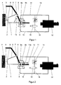
- FIG. 1 is a sketchy representation of an embodiment of a non-inventive suspension visible.
- a lower wishbone 1 is pivotally attached at one end via a ball joint 2 to a wheel carrier 3, on which the vehicle wheel 4 is arranged.
- an upper wishbone 5 is pivotally mounted with its one end via a ball joint 6 on the wheel carrier 3 and with its other end via a rubber hinge 7 on the vehicle body 8.
- the other end of the lower arm 1 is connected to the motor shaft 9 a of a swing motor 9, the housing 9 b is fixed to the vehicle body 8.
- the swing motor 9 is connected via a first hydraulic line 10 and via a second hydraulic line 11 to a hydraulic pump 12, from which the hydraulic swing motor 9 hydraulic fluid can be supplied. Depending on whether the hydraulic fluid flows through the hydraulic line 10 or through the hydraulic line 11 in the pivot motor 9, the lower arm 1 can be pivoted together with the vehicle 4 to the vehicle body 8 and pivoted away from it.
- vehicle spring 13 For Aufnahe of at least a portion of the force exerted by the vehicle body 8 on the vehicle 4 load between the lower arm 1 and the vehicle body 8 designed as an air spring vehicle spring 13 is arranged with its one end at a distance from the motor shaft 9a on the lower arm 1 and with its other end is fixed to the vehicle body 8 and thus relieves the swing motor 9 in maintaining the distance between the vehicle wheel 4 and the vehicle body 8.
- the vehicle spring 13 is attached according to this embodiment with its one end to the lower arm 1, but according to another embodiment, it is also possible to fasten the vehicle spring 13 with its one end to the upper arm 5.
- FIG. 2 is a sketchy representation of an embodiment of the suspension according to the invention can be seen, for identical or functionally identical features the same reference numerals as in the first embodiment are used.
- the lower wishbone 1 has a beyond its point of articulation to the vehicle body 8 extending beyond extension 13a, on which the vehicle spring 13 is fixed at a distance from the motor shaft 9a with its one end. Except for the extension 13a of the handlebar 1 and the attachment of the vehicle spring 13 to this extension 13a, the embodiment of the present invention coincides with the embodiment not according to the invention.
- extension 13a By forming the extension 13a on the lower arm 1, it has become possible to arrange the vehicle spring 13 outside the space between the vehicle body 8 and the vehicle wheel 4, so that this space can be used for arranging other automobile components.
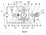
- FIG. 3 is a detailed schematic diagram of a controlled vane pump can be seen as the hydraulic pump 12 for the two embodiments according to the Figures 1 and 2 can be used.
- the hydraulic throttle 14, the valve 15 and the secondary line 16 are not shown in this figure.
- the hydraulic pump 12 is realized in the form of a vane pump, which has a shaft 18 which is rotatably mounted in a housing 17 and driven by an electric motor (not shown), which shaft is rotatably and fluid-tightly mounted in the housing 17.
- a plurality of radially outwardly projecting fins 19 are arranged around its circumference, which can vary their radial distance from the center line 18a of the shaft 18 in a usual manner for vane pumps manner.
- the shaft 18 is arranged in a cylindrical and filled with hydraulic fluid pump chamber 20 which is formed in a arranged in the housing 17 reciprocating piston 21 which is perpendicular to the center line 18 a of the shaft 18 in the direction of arrow P via guide bands or piston rings 22 in the housing 17 is slidably mounted.
- Perpendicular to the central axis 18a of the shaft 18 and perpendicular to the direction of movement P are two oppositely extending passages 21a and 21b (shown in phantom) formed in the reciprocating piston 21 extending from the pump chamber 20 through the reciprocating piston 21 into a first transition chamber 23a and in a second transition chamber 23b extend.
- the two transition chambers 23a and 23b (shown in dashed lines) are in turn connected to the hydraulic lines 10 and 11 via two oppositely extending and extending through the housing 17 additional passages 24a and 24b (shown in phantom) and lie with respect to the central axis 17a (shown in phantom) of the housing 17 diametrically opposite each other.
- one is Connection of the pump chamber 20 via the first transition chamber 23 a with the first hydraulic line 10 and a connection of the pump chamber 20 via the second transition chamber 23 b with the second hydraulic line 11 with the interposition of the passages 21 a, 21 b, 24 a and 24 b created.
- the two transition chambers 23a and 23b are formed according to this embodiment in the inner wall of the housing 17, but they can be provided according to another embodiment, in the lateral surface of the piston 21.
- the amount of hydraulic fluid delivered by the hydraulic pump 12 can be adjusted, wherein in that position of the piston 21, in which the pump chamber 20 is arranged concentrically to the shaft 18, no hydraulic fluid is conveyed.
- the lamellae 19 Due to the centrifugal force or due to the spring force of arranged in the shaft 18 springs (not shown), the lamellae 19 are pushed radially outwardly from the shaft 18 and lie with their the center line 18a of the shaft 18 opposite ends on the inner wall of the pump chamber 20 at. How out FIG. 3 can be seen, the reciprocating piston 21- and thus the center line 20a of the pump chamber 20 - relative to the center line 18a of the shaft 18 is shifted to the left, so that an eccentricity between the pump chamber 20 and the shaft 18 is formed.
- the displacement of the lifting piston 21 in the housing 17 along the center line 17a it is thus possible to set in which direction and at which throughput the hydraulic fluid is conveyed by the hydraulic pump 12.
- this also simultaneously sets the pressure difference between the pressures in the two hydraulic lines 10 and 11, which determines the torque output by the motor 9 via the motor shaft 9a, via which the pivot angle of the lower arm 1 and thus also the distance of the vehicle wheel 4 from Vehicle body 8 is adjustable.
- the two chambers formed between the end faces of the lifting piston 21 and the housing 17 are connected to one another via at least one compensating groove 21c formed in the lateral surface of the lifting piston 21, through which hydraulic fluid can be exchanged between the two chambers during displacement of the lifting piston 21.
- According to another embodiment may be provided in the housing 17 or a bore in the reciprocating piston 21 instead of or in addition to the Kompensationsnut 21c also connecting these chambers.
- a predetermined hydraulic torque difference between the pressures in the two hydraulic lines 10 and 11 is set as a setpoint pressure difference via a setpoint generator 25, the one Has mechanically with one of the two end faces of the reciprocating piston 21 coupled and made of magnetic material actuator piston 26 which is slidably disposed in an electric coil 27.
- the electric coil 27 is controlled via an electronic control unit (not shown) such that on the adjusting piston 26 via the magnetic field generated by the electric coil 27, a force is exerted because of the mechanical coupling of the actuating piston 26 with the one end face of the reciprocating piston 21st also acts simultaneously on the reciprocating piston 21.
- the desired setpoint pressure difference can be adjusted by the reciprocating piston 21 is shifted to a setpoint pressure difference assigned setpoint position .
- the frequency with which the reciprocating piston 21 can be moved back and forth between the nominal value transmitter 25 and different setpoint positions was approximately 5 Hz in a test setup.
- the reciprocating piston 21 is coupled with its other end face to the housing 17 of the hydraulic pump 12 via a mechanical spring 28 which is dimensioned such that the pump chamber 20 is brought into the concentric position with the shaft 18, if only the force of the mechanical Spring 28 acts on the reciprocating piston 21.
- the mechanical spring 28 thus has inter alia the function to bring the reciprocating piston 21 after switching off or failure of the hydraulic pump 12 in a certain position so that when switching on the hydraulic pump 12, a defined starting state for the reciprocating piston 21 is present.
- the electric coil 27 is controlled by the electronic control unit such that the setpoint generator 25 applies sufficient to maintain the setpoint pressure difference.
- the reciprocating piston 21 can thus be considered to be mounted between two springs 25 and 28, wherein the force output by the spring formed by the setpoint generator 25 via the electronic control unit is adjustable. Is it due to a fault to one Displacement of the reciprocating piston 21, so the springs 25 and 28 after decay of this disorder the reciprocating piston 21 back to its setpoint position.
- an electric motor is used, which drives a linear actuator via a transmission, which is coupled via a mechanical spring with the reciprocating piston 21.
- a cylindrical control piston 29, 30 is mechanically coupled, wherein a first of the control piston 29 slidably and liquid-tightly engages in a closed on one side first hollow cylinder 31 and the second control piston 30 slidably and liquid-tight in a closed second hollow cylinder 32 ,
- the hydraulic chambers formed between the control piston 29 and 30 and the inner wall of the two hollow cylinders 31 and 32 are each filled with hydraulic fluid and via two hydraulic control lines 33 and 34 with the interposition of two hydraulic throttles 35 and 36 with the first and the second hydraulic line 10, 11 connected, so that with this arrangement, a hydraulic control is realized, which maintains the setpoint pressure difference taking into account the current hydraulic pressure difference between the pressures in the two hydraulic lines 10 and 11.
Description
Die Erfindung betrifft eine Radaufhängung für ein Kraftfahrzeug nach dem Oberbegriff des Patentanspruches 1.The invention relates to a suspension for a motor vehicle according to the preamble of
Radaufhängungen bei denen der Lenker zum Beispiel über ein Kugelgelenk an einem das Fahrzeugrad aufnehmenden Radträger und über ein Gummilager an dem Fahrzeugaufbau befestigt ist, sind aus dem Stand der Technik bekannt. Zwischen dem Lenker und dem Fahrzeugaufbau sind ferner ein Stoßdämpfer und eine Fahrzeugfeder angeordnet, von welcher der Fahrzeugaufbau im Abstand zu dem Fahrzeugrad gehalten wird. Der Fahrkomfort ist dabei in erheblicher Weise von der Federkennlinie der Fahrzeugfeder und von dem Dämpfungsverhalten des Stoßdämpfers abhängig.Wheel suspensions in which the handlebar is attached, for example, via a ball joint to a wheel carrier accommodating the vehicle wheel and to the vehicle body via a rubber mount, are known from the prior art. Between the handlebar and the vehicle body further a shock absorber and a vehicle spring are arranged, of which the vehicle body is kept at a distance from the vehicle wheel. The ride comfort is significantly dependent on the spring characteristic of the vehicle spring and the damping behavior of the shock absorber.
Zum Verbessern der Wankeigenschaften bei Kurvenfahrten kann zusätzlich ein Stabilisator zwischen den beiden Fahrzeugrädern einer Achse des Kraftfahrzeugs angeordnet sein. Häufig wird als Stabilisator ein Torsionsfederstab verwendet, der mit seinem einen Ende über eine erste Pendelstütze mit einem ersten der beiden Fahrzeugräder und mit seinem anderen Ende über eine zweite Pendelstütze mit dem zweiten Fahrzeugrad verbunden ist, wobei der zwischen den beiden Enden liegende Mittelteil des Stabilisators am Fahrzeugaufbau gelagert ist. Die Pendelstützen können dabei mit ihren dem Stabilisator abgewandten Enden an den die Räder aufnehmenden Radträgern oder an den die Radträger mit dem Fahrzeugaufbau verbindenden Lenkern befestigt sein.To improve the rolling properties when cornering, a stabilizer between the two vehicle wheels of an axle of the motor vehicle may additionally be arranged. Often, a torsion spring rod is used as a stabilizer, which is connected at one end via a first pendulum support with a first of the two vehicle wheels and at its other end via a second pendulum support to the second vehicle, wherein the middle part of the stabilizer lying between the two ends Vehicle body is stored. The pendulum supports can be fastened with their ends facing away from the stabilizer on the wheel carriers receiving the wheels or on the links connecting the wheel carriers to the vehicle body.
Eine derartige Radaufhängung hat aber den Nachteil, dass die Federkennlinie der Fahrzeugfeder, das Dämpfungsverhalten des Stoßdämpfers und die Federkennlinie des Stabilisators regelmäßig nicht verändert werden können, ohne eines dieser Bauteile durch ein anderes mit anderen Eigenschaften zu ersetzen.However, such a suspension has the disadvantage that the spring characteristic of the vehicle spring, the damping behavior of the shock absorber and the spring characteristic of the stabilizer can not be changed regularly without replacing one of these components by another with different properties.
Die gattungsbildende
Darüber hinaus wird in der
Ergänzend ist es aus der
Eine derartige Vorrichtung zur Kurvenstabilisierung eines Kraftfahrzeugs weist allerdings den Nachteil auf, dass beide Räder einer Achse über den Stabilisator miteinander verbunden sind, was der Idee einer Einzelradaufhängung zuwiderläuft, das Fahrzeugrad separat an den Fahrzeugaufbau anzubinden.However, such a device for stabilizing the curve of a motor vehicle has the disadvantage that both wheels of an axle are connected to one another via the stabilizer, which runs counter to the idea of an independent suspension to connect the vehicle wheel separately to the vehicle body.
Aufgabe der Erfindung ist es, eine Radaufhängung für ein Kraftfahrzeug zu schaffen, bei der die Eigenschaften der Anbindung des Fahrzeugrades an den Fahrzeugaufbau separat und aktiv beeinflusst werden können und der Fahrkomfort insgesamt verbessert wird.The object of the invention is to provide a suspension for a motor vehicle, in which the properties of the connection of the vehicle wheel to the vehicle body can be influenced separately and actively and ride comfort is improved overall.
Diese Aufgabe wird durch eine Radaufhängung mit den Merkmalen nach Patentanspruch 1 gelost. Bevorzugte Weiterbildungen sind in den Unteransprüchen beschrieben.This object is achieved by a suspension with the features of
Erfindungsgemäß weist die Radaufhängung für ein Kraftfahrzeug einen zwischen einem Fahrzeugrad und dem Fahrzeugaufbau angeordneten Lenker auf, der mit seinem einen Ende schwenkbar mit dem Fahrzeugrad und mit seinem anderen Ende schwenkbar mit dem Fahrzeugaufbau gekoppelt ist. Der Lenker ist dabei über einen Schwenkmotor mit dem Fahrzeugaufbau verbunden und um die Schwenkachse des Schwenkmotors schwenkbar. Da der Lenker mit seinem dem Schwenkmotor abgewandten Ende an dem Fahrzeugrad befestigt ist, kann über das Betätigen des Schwenkmotors der Abstand zwischen dem Fahrzeugrad und dem Fahrzeugaufbau eingestellt werden. Ferner sind über den Schwenkmotor sowohl das Federungsverhalten als auch das Dämpfungsverhalten des Fahrzeugrades gegenüber dem Fahrzeugaufbau steuerbar, so dass die Eigenschaften der Anbindung des Fahrzeugrads an den Fahrzeugaufbau separat und aktiv beeinflusst werden können. Darüber hinaus kann der regelmäßig in Kraftfahrzeugen verwendete Stoßdämpfer entfallen, dessen Aufgabe nun von dem Schwenkmotor der erfindungsgemäßen Radaufhängung wahrnehmbar ist.According to the invention, the suspension for a motor vehicle on a arranged between a vehicle and the vehicle body arm, which is pivotally coupled at one end pivotally connected to the vehicle and at its other end pivotally connected to the vehicle body. The handlebar is connected via a pivot motor with the vehicle body and pivotable about the pivot axis of the swing motor. Since the handlebar is fastened with its end facing away from the swivel motor to the vehicle wheel, the distance between the vehicle wheel and the vehicle body can be adjusted via the actuation of the swivel motor. Furthermore, both the suspension behavior and the damping behavior of the vehicle wheel relative to the vehicle body can be controlled via the swivel motor, so that the properties of the connection of the vehicle wheel to the vehicle body can be influenced separately and actively. In addition, the shock absorber used regularly in motor vehicles can be omitted, the task of which is now perceptible by the swing motor of the suspension according to the invention.
Mit dem Schwenkmotor kann auf eine Fahrzeugfeder verzichtet werden, wenn der Schwenkmotor während des Einsatzes des Kraftfahrzeugs einen ausreichenden Abstand zwischen dem Fahrzeugrad und dem Fahrzeugaufbau aufrechterhält. Ein derartiger Betrieb des Schwenkmotors bringt aber einen hohen Energieverbrauch mit sich, so dass zwischen dem Fahrzeugrad und dem Fahrzeugaufbau eine Fahrzeugfeder angeordnet ist, die mittelbar oder unmittelbar mit ihrem einen Ende mit dem Fahrzeugrad und mit ihrem anderen Ende mit dem Fahrzeugaufbau verbunden ist.With the pivot motor can be dispensed with a vehicle spring, when the pivot motor during use of the motor vehicle maintains a sufficient distance between the vehicle and the vehicle body. However, such operation of the slewing motor brings a high energy consumption, so that between the vehicle and the vehicle body, a vehicle spring is arranged, which is directly or indirectly connected at one end to the vehicle and at the other end to the vehicle body.
Unter einer unmittelbaren Verbindung der Fahrzeugfeder mit dem Fahrzeugrad ist dabei zum Beispiel die Anbindung des einen Endes der Fahrzeugfeder an einen das Fahrzeugrad aufnehmenden Radträger zu verstehen. Bei einer mittelbaren Verbindung der Fahrzeugfeder mit dem Fahrzeugrad kann das eine Ende der Fahrzeugfeder auch an einem das Fahrzeugrad mit dem Fahrzeugaufbau verbindenden Fahrwerkbauteil befestigt sein, wobei die Fahrzeugfeder mit ihrem einen Ende im Abstand zum Schwenkmotor bzw. zum Fahrzeugaufbau an dem Lenker befestigt ist.Under an immediate connection of the vehicle spring with the vehicle is to understand, for example, the connection of one end of the vehicle spring to a wheel carrier receiving the vehicle. In an indirect connection of the vehicle spring with the vehicle wheel, one end of the vehicle spring may also be fastened to a chassis component which connects the vehicle wheel to the vehicle body, wherein the vehicle spring is fastened with its one end at a distance to the pivot motor or to the vehicle body on the handlebar.
Falls die Fahrzeugfeder mit ihrem einen Ende an dem Lenker befestigt ist, kann sie weit in den Raumbereich zwischen dem Fahrzeugrad und dem Fahrzeugaufbau hineinreichen.If the vehicle spring is fastened with its one end to the handlebar, it can extend far into the space between the vehicle wheel and the vehicle body.
Dieser Raumbereich ist aber häufig für andere Bauteile im Kraftfahrzeug vorgesehen, so dass der Lenker eine über seinen Anbindungspunkt an dem Schwenkmotor bzw. dem Fahrzeugaufbau hinausreichende Verlängerung aufweist, an welcher die Fahrzeugfeder mit ihrem einen Ende befestigt ist. Somit ist es möglich, die Fahrzeugfeder in nur einem kleinen Bereich innerhalb oder sogar vollständig außerhalb dieses Raumbereiches anzuordnen.However, this space area is often provided for other components in the motor vehicle, so that the handlebar has an extension beyond its connection point to the pivot motor or the vehicle body extension, to which the vehicle spring is attached with its one end. Thus, it is possible to arrange the vehicle spring in only a small area within or even completely outside this space area.
Der Schwenkmotor kann entsprechend einer Ausgestaltung der Erfindung unmittelbar mit dem Lenker und/oder dem Fahrzeugaufbau verbunden sein. Bevorzugt ist zwischen dem Schwenkmotor und dem Lenker und/oder zwischen dem Schwenkmotor und dem Fahrzeugaufbau aber ein mechanisches Dämpfungselement angeordnet, welches vom Schwenkmotor ausgehende ruckartige Bewegungen gedämpft an den Lenker und/oder den Fahrzeugaufbau weitergibt wodurch der Fahrkomfort erhöht wird.The swivel motor can be connected directly to the handlebar and / or the vehicle body according to an embodiment of the invention. Preferably, however, a mechanical damping element is arranged between the swivel motor and the link and / or between the swivel motor and the vehicle body, which transmits jerky movements emanating from the swivel motor to the driver and / or the vehicle body, whereby the ride comfort is increased.
Die Fahrzeugfeder kann eine Elastomerfeder oder eine Stahlfeder zum Beispiel in Form einer Schraubenfeder sein, die hinsichtlich ihrer Federkennlinie ein nahezu identisches Verhalten bei statischer und dynamischer Belastung aufweist. Bevorzugt ist die Fahrzeugfeder aber eine Luftfeder, die eine über den Luftdruck variierbare Federkennlinie und Unterschiede in ihrem dynamischen und in ihrem statischen Verhalten aufweist, so dass das Federverhalten der Radaufhängung in gewünschter Weise an unterschiedliche Fahrsituationen angepasst werden kann, ohne die Fahrzeugfeder selbst austauschen zu müssen.The vehicle spring may be an elastomer spring or a steel spring, for example in the form of a helical spring, which has a nearly identical behavior with respect to their spring characteristic under static and dynamic load. Preferably, however, the vehicle spring is an air spring which has a spring characteristic which can be varied via the air pressure and differences in its dynamic and static behavior, so that the spring behavior of the wheel suspension can be adapted to different driving situations in a desired manner without having to replace the vehicle spring itself ,
Der Schwenkmotor kann elektrisch oder pneumatisch betrieben werden. Bevorzugt wird der Schwenkmotor jedoch hydraulisch betrieben und ist über Hydraulikleitungen mit einer geregelten Hydraulikpumpe verbunden, da ein hydraulisch betriebener Schwenkmotor regelmäßig schneller gesteuert werden kann als ein rein pneumatisch betriebener Schwenkmotor, bei dem die große Kompressibilität der Luft einer schnellen Steuerbarkeit entgegenwirkt. Bei dem an sich ausreichend schnellen elektrischen Schwenkmotor stellt sich im Kraftfahrzeug das Problem der elektrischen Energieversorgung. Eine plötzlich auftretende Lasterhöhung kann mit einem großen elektrischen Leistungsbedarf verbunden sein, der aufgrund der verwendeten Kraftfahrzeugbatterie mit einer Spannung von 12V oder 24V häufig nicht gedeckt werden kann.The swivel motor can be operated electrically or pneumatically. Preferably, however, the swivel motor is operated hydraulically and is connected via hydraulic lines with a regulated hydraulic pump, since a hydraulically operated swivel motor can be regularly controlled faster than a purely pneumatically operated swivel motor, in which the great compressibility of the air of rapid controllability counteracts. In the sufficiently fast electric swivel motor, the problem arises in the motor vehicle of the electric power supply. A sudden increase in load can be associated with a large electrical power requirement, which can often not be covered due to the motor vehicle battery used with a voltage of 12V or 24V.
Die Hydraulikpumpe kann zum Beispiel in Form einer Zahnradpumpe ausgeführt sein. Bevorzugt ist die Hydraulikpumpe aber eine elektrisch angetriebene Flügelzellenpumpe, da diese schneller zwischen unterschiedlichen hydraulischen Druckstufen hin- und hergeschaltet werden kann.The hydraulic pump can be designed, for example, in the form of a gear pump. Preferably, however, the hydraulic pump is an electrically driven vane-cell pump, since it can be switched back and forth more quickly between different hydraulic pressure stages.
Die Hydraulikpumpe kann mechanisch, elektrisch oder pneumatisch geregelt werden. Bevorzugt weist die Hydraulikpumpe aber eine mit den Hydraulikleitungen verbundene hydraulische Regeleinrichtung zum Aufrechterhalten einer vorbestimmten hydraulischen Druckdifferenz (Sollwert) zwischen den Drücken in den Hydraulikleitungen auf, da eine hydraulische Regelung sehr systemnah und zum Beispiel ohne die Umwandlung von mechanischen in elektrische Größen realisiert werden kann.The hydraulic pump can be controlled mechanically, electrically or pneumatically. Preferably, however, the hydraulic pump has a hydraulic control device connected to the hydraulic lines for maintaining a predetermined hydraulic pressure difference (setpoint) between the pressures in the hydraulic lines, since a hydraulic control can be implemented very close to the system and, for example, without the conversion from mechanical to electrical variables.
Die vorbestimmte hydraulische Druckdifferenz zwischen den Drücken in den Hydraulikleitungen kann unveränderbar sein. Bevorzugt ist aber mit der Hydraulikpumpe ein elektrisch gesteuerter Sollwertgeber zum Einstellen der vorbestimmten hydraulischen Druckdifferenz gekoppelt. Damit wird berücksichtigt, dass zum Beispiel je nach Beladungszustand des Kraftfahrzeugs ein unterschiedlicher Sollwert für die hydraulische Regeleinrichtung eingestellt werden kann. Anstelle eines elektrisch gesteuerten Sollwertgebers kann allerdings auch ein mechanisch, pneumatisch oder hydraulisch gesteuerter Sollwertgeber verwendet werden.The predetermined hydraulic pressure difference between the pressures in the hydraulic lines may be unchangeable. Preferably, however, is coupled to the hydraulic pump, an electrically controlled setpoint generator for setting the predetermined hydraulic pressure difference. This takes into account that, for example, depending on the load condition of the motor vehicle, a different setpoint for the hydraulic control device can be set. Instead of an electrically controlled setpoint generator, however, a mechanically, pneumatically or hydraulically controlled setpoint generator can be used.
Die Erfindung wird anhand bevorzugter Ausführungsformen unter Bezugnahme auf die Zeichnung beschrieben. In der Zeichnung zeigen:
- Figur 1:
- eine skizzenhafte Darstellung einer Ausführungsform einer nicht erfindungsgemäßen Radaufhängung,
- Figur 2:
- eine skizzenhafte Darstellung einer Ausführungsform der erfindungsgemäßen Radaufhängung und
- Figur 3:
- eine detaillierte Prinzipdarstellung einer geregelten Flügelzellenpumpe, die als Hydraulikpumpe für die beiden Ausführungsformen nach den
Figuren 1 und 2
- FIG. 1:
- a sketch of an embodiment of a non-inventive suspension,
- FIG. 2:
- a sketchy representation of an embodiment of the suspension of the invention and
- FIG. 3:
- a detailed schematic diagram of a controlled vane pump, as a hydraulic pump for the two embodiments according to the
Figures 1 and 2 can be used.
Aus
Der Schwenkmotor 9 ist über eine erste Hydraulikleitung 10 und über eine zweite Hydraulikleitung 11 mit einer Hydraulikpumpe 12 verbunden, von welcher dem hydraulischen Schwenkmotor 9 Hydraulikflüssigkeit zugeführt werden kann. Je nachdem, ob die Hydraulikflüssigkeit durch die Hydraulikleitung 10 oder durch die Hydraulikleitung 11 in den Schwenkmotor 9 strömt, kann der untere Querlenker 1 zusammen mit dem Fahrzeugrad 4 zu dem Fahrzeugaufbau 8 hingeschwenkt bzw. von diesem weggeschwenkt werden.The
Zur Aufnahe von zumindest einem Teil der von dem Fahrzeugaufbau 8 auf das Fahrzeugrad 4 ausgeübten Last ist zwischen dem unteren Querlenker 1 und dem Fahrzeugaufbau 8 eine als Luftfeder ausgebildete Fahrzeugfeder 13 angeordnet, die mit ihrem einen Ende im Abstand zu der Motorwelle 9a an dem unteren Querlenker 1 und mit ihrem anderen Ende an dem Fahrzeugaufbau 8 befestigt ist und somit den Schwenkmotor 9 beim Aufrechterhalten des Abstands zwischen dem Fahrzeugrad 4 und dem Fahrzeugaufbau 8 entlastet. Zwar ist die Fahrzeugfeder 13 nach dieser Ausführungsform mit ihrem einen Ende an dem unteren Querlenker 1 befestigt, allerdings ist es nach einer anderen Ausführungsform auch möglich, die Fahrzeugfeder 13 mit ihrem einen Ende an dem oberen Querlenker 5 zu befestigen.For Aufnahe of at least a portion of the force exerted by the
Für den Fall, dass aufgrund eines Defekts in der Hydraulikpumpe 12 keine Hydraulikflüssigkeit mehr zwischen den beiden Hydraulikleitungen 10 und 11 über die Hydraulikpumpe 12 ausgetauscht werden kann, ist zwischen den Hydraulikleitungen 10 und 11 eine Reihenschaltung aus einer Hydraulikdrossel 14 und einem Ventil 15 vorgesehen, so dass über ein Öffnen des Ventils 15 eine Nebenleitung (Bypass) 16 zwischen den beiden Hydraulikleitungen 10 und 11 mit einem über die Hydraulikdrossel 14 eingestellten Strömungswiderstand für die Hydraulikflüssigkeit eingerichtet werden kann. Damit ist es möglich, trotz eines Ausfalls der Hydraulikpumpe 12 die Motorwelle 9a des Schwenkmotors 9 zu bewegen und den unteren Querlenker 1 zu schwenken, wobei die Nebenleitung 16 wie ein Stoßdämpfer wirkt, dessen Eigenschaften über die Hydraulikdrossel 14 eingestellt werden können. Das Ventil 15 wird von einer nicht dargestellten elektronischen Steuerungs- und Überwachungseinrichtung betätigt, die den Ausfall der Hydraulikpumpe 12 über geeignete Sensoren erfassen kann.In the event that due to a defect in the
Aus
Durch das Ausbilden der Verlängerung 13a an dem unteren Querlenker 1 ist es möglich geworden, die Fahrzeugfeder 13 außerhalb des Raumes zwischen dem Fahrzeugaufbau 8 und dem Fahrzeugrad 4 anzuordnen, so dass dieser Raum für das Anordnen von anderen Kraftfahrzeugbauteilen verwendet werden kann.By forming the
Aus
Die Hydraulikpumpe 12 ist in Form einer Flügelzellenpumpe realisiert, die eine in einem Gehäuse 17 drehbar gelagerte und über einen Elektromotor (nicht gezeigt) angetriebene Welle 18 aufweist, die drehbar und flüssigkeitsdicht in dem Gehäuse 17 gelagert ist. In der Welle 18 sind rings ihres Umfangs mehrere, radial nach außen abstehende Lamellen 19 angeordnet, die ihren radialen Abstand zur Mittellinie 18a der Welle 18 in einer für Flügelzellenpumpen üblichen Art und Weise variieren können. Die Welle 18 ist in einer zylinderförmigen und mit Hydraulikflüssigkeit gefüllten Pumpenkammer 20 angeordnet, die in einem in dem Gehäuse 17 angeordneten Hubkolben 21 ausgebildet ist, der senkrecht zur Mittellinie 18a der Welle 18 in Richtung des Pfeils P über Führungsbänder bzw. Kolbenringe 22 in dem Gehäuse 17 verschiebbar gelagert ist.The
Senkrecht zur Mittelachse 18a der Welle 18 und senkrecht zur Bewegungsrichtung P sind zwei entgegengesetzt verlaufende Durchführungen 21a und 21b (gestrichelt dargestellt) in dem Hubkolben 21 ausgebildet, die sich von der Pumpenkammer 20 durch den Hubkolben 21 hindurch in eine erste Übergangskammer 23a bzw. in eine zweite Übergangskammer 23b erstrecken. Die beiden Übergangskammern 23a und 23b (gestrichelt dargestellt) sind ihrerseits über zwei entgegengesetzt verlaufende und sich durch das Gehäuse 17 hindurcherstreckende zusätzliche Durchführungen 24a und 24b (gestrichelt dargestellt) mit den Hydraulikleitungen 10 bzw. 11 verbunden und liegen hinsichtlich der Mittelachse 17a (gestrichelt dargestellt) des Gehäuses 17 einander diametral gegenüber. Somit ist eine Verbindung der Pumpenkammer 20 über die erste Übergangskammer 23a mit der ersten Hydraulikleitung 10 und eine Verbindung der Pumpenkammer 20 über die zweite Übergangskammer 23b mit der zweiten Hydraulikleitung 11 unter Zwischenschaltung der Durchführungen 21a, 21b, 24a und 24b geschaffen. Zwar sind die beiden Übergangskammern 23a und 23b gemäß dieser Ausführungsform in der Innenwandung des Gehäuses 17 ausgebildet, allerdings können sie nach einer anderen Ausführungsform auch in der Mantelfläche des Hubkolbens 21 vorgesehen sein.Perpendicular to the
Je nach Stellung des Hubkolbens 21 lässt sich die von der Hydraulikpumpe 12 geförderte Menge an Hydraulikflüssigkeit einstellen, wobei in derjenigen Stellung des Hubkolbens 21, in der die Pumpenkammer 20 konzentrisch zur Welle 18 angeordnet ist, keine Hydraulikflüssigkeit gefördert wird.Depending on the position of the
Aufgrund der Fliehkraft oder aufgrund der Federkraft von in der Welle 18 angeordneten Federn (nicht gezeigt) werden die Lammellen 19 radial nach außen aus der Welle 18 herausgedrückt und liegen mit ihren der Mittellinie 18a der Welle 18 abgewandten Enden an der Innenwandung der Pumpenkammer 20 an. Wie aus
Wird der Hubkolben 21 derart verschoben, dass die Mittellinie 20a der Pumpenkammer 20 rechts von der Mittellinie 18a der Welle 18 liegt, so führt diese Exzentrizität von Pumpenkammer 20 und Welle 18 dazu, dass die Hydraulikflüssigkeit aus der zweiten Übergangskammer 23b heraus, durch die Pumpenkammer 20 hindurch und in die erste Übergangskammer 23a hinein gefördert wird. In diesem Fall fließt die Hydraulikflüssigkeit von der Hydraulikpumpe 12 durch die erste Hydraulikleitung 10 in den Schwenkmotor 9, so dass dieser ein im entgegengesetzten Sinne des Pfeils M orientiertes Drehmoment an die Motorwelle 9a abgibt. Danach fließt die Hydraulikflüssigkeit von dem hydraulischen Schwenkmotor 9 durch die zweite Hydraulikleitung 11 wieder zurück in die Hydraulikpumpe 12.If the
Über die Verschiebung des Hubkolbens 21 in dem Gehäuse 17 längs der Mittellinie 17a lässt sich also einstellen, in welche Richtung und mit welchem Durchsatz die Hydraulikflüssigkeit von der Hydraulikpumpe 12 gefördert wird. Damit wird aber auch gleichzeitig die Druckdifferenz zwischen den Drücken in den beiden Hydraulikleitungen 10 und 11 eingestellt, welche das von dem Motor 9 über die Motorwelle 9a abgegebene Drehmoment bestimmt, über welches der Schwenkwinkel des unteren Querlenkers 1 und somit auch der Abstand des Fahrzeugrades 4 vom Fahrzeugaufbau 8 einstellbar ist. Die beiden zwischen den Stirnseiten des Hubkolbens 21 und dem Gehäuse 17 gebildeten Kammern sind dabei über wenigstens eine in der Mantelfläche des Hubkolbens 21 ausgebildete Kompensationsnut 21c miteinander verbunden, durch welche beim Verschieben des Hubkolbens 21 Hydraulikflüssigkeit zwischen den beiden Kammern ausgetauscht werden kann. Nach einer anderen Ausführungsform kann anstelle oder ergänzend zu der Kompensationsnut 21c auch eine diese Kammern verbindende Leitung im Gehäuse 17 oder eine Bohrung im Hubkolben 21 vorgesehen sein.By means of the displacement of the
Um ein vorbestimmtes Drehmoment an die Motorwelle 9b des hydraulischen Schwenkmotors 9 abzugeben, wird eine dem vorbestimmten Drehmoment entsprechende hydraulische Druckdifferenz zwischen den Drücken in den beiden Hydraulikleitungen 10 und 11 als Sollwertdruckdifferenz über einen Sollwertgeber 25 eingestellt, der einen mechanisch mit einer der beiden Stirnseiten des Hubkolbens 21 gekoppelten und aus magnetischem Werkstoff hergestellten Stellkolben 26 aufweist, welcher verschiebbar in einer elektrischen Spule 27 angeordnet ist. Die elektrische Spule 27 wird über ein elektronisches Steuergerät (nicht gezeigt) derart angesteuert, dass auf den Stellkolben 26 über das von der elektrischen Spule 27 erzeugte Magnetfeld eine Stellkraft ausgeübt wird, die wegen der mechanischen Kopplung des Stellkolbens 26 mit der einen Stirnseite des Hubkolbens 21 auch gleichzeitig auf den Hubkolben 21 wirkt. Da eine aus der Stellkraft resultierende Verschiebung des Hubkolbens 21 eine Veränderung der hydraulischen Druckdifferenz zwischen den Drücken in den beiden Hydraulikleitungen 10 und 11 bewirkt, kann über den Sollwertgeber 25 die gewünschte Sollwertdruckdifferenz eingestellt werden, indem der Hubkolben 21 in eine der Sollwertdruckdifferenz zugeordnete Sollwertposition verschoben wird. Die Frequenz, mit welcher der Hubkolben 21 von dem Sollwertgeber 25 zwischen unterschiedlichen Sollwertpositionen hin- und hergeschoben werden kann, lag in einem Versuchsaufbau bei ungefähr 5 Hz.In order to deliver a predetermined torque to the
Wie aus
Nachdem die Sollwertdruckdifferenz eingestellt ist, wird die elektrische Spule 27 von dem elektronischen Steuergerät derart angesteuert, dass der Sollwertgeber 25 eine zum Aufrechterhalten der Sollwertdruckdifferenz ausreichende Kraft aufbringt. Der Hubkolben 21 kann somit als zwischen zwei Federn 25 und 28 gelagert betrachtet werden, wobei die von der durch den Sollwertgeber 25 gebildeten Feder abgegebene Kraft über das elektronische Steuergerät einstellbar ist. Kommt es aufgrund einer Störung zu einer Verschiebung des Hubkolbens 21, so stellen die Federn 25 und 28 nach Abklingen dieser Störung den Hubkolben 21 wieder in seine Sollwertposition zurück.After the setpoint pressure difference is set, the
Anstelle des in der elektrischen Spule 27 verschiebbar angeordneten Stellkolbens 26 aus magnetischem Werkstoff kann nach einer anderen Ausführungsform für den Sollwertgeber 25 auch ein Elektromotor verwendet werden, der über ein Getriebe ein lineares Stellglied antreibt, das über eine mechanische Feder mit dem Hubkolben 21 gekoppelt ist.Instead of the displaceably arranged in the
Mit den beiden Stirnseiten des Hubkolbens 21 ist jeweils ein zylinderförmiger Steuerkolben 29, 30 mechanisch gekoppelt, wobei ein erster der Steuerkolben 29 gleitfähig und flüssigkeitsdicht in einen einseitig geschlossenen ersten Hohlzylinder 31 und der zweite Steuerkolben 30 gleitfähig und flüssigkeitsdicht in einen einseitig geschlossenen zweiten Hohlzylinder 32 eingreift. Die zwischen den Steuerkolben 29 und 30 und der Innenwandung der beiden Hohlzylinder 31 und 32 gebildeten Hydraulikkammern sind jeweils mit Hydraulikflüssigkeit gefüllt und über zwei hydraulische Steuerleitungen 33 und 34 unter Zwischenschaltung von zwei hydraulischen Drosseln 35 und 36 mit der ersten bzw. der zweiten Hydraulikleitung 10, 11 verbunden, so dass mit dieser Anordnung eine hydraulische Regelung realisiert ist, die unter Berücksichtigung der aktuellen hydraulischen Druckdifferenz zwischen den Drücken in den beiden Hydraulikleitungen 10 und 11 die Sollwertdruckdifferenz aufrechterhält.With the two end faces of the
Kommt es aufgrund einer Lastschwankung im Schwenkmotor 9 zu einer Veränderung in der hydraulischen Druckdifferenz (Druckdifferenzschwankung) zwischen den Drücken in den beiden Hydraulikleitungen 10 und 11, so wird diese Druckdifferenzschwankung über die beiden Steuerleitungen 33 und 34 an die Hydraulikkammern in den beiden Hohlzylindern 31 und 32 weitergegeben. Die daraus resultierende Änderung des Drucks in den Hohlzylindern 31, 32 bewirkt eine Verschiebung der beiden Steuerkolben 29 und 30, was wegen der mechanischen Kopplung der Steuerkolben 29, 30 mit dem Hubkolben 21 auch zu einer Verschiebung des Hubkolbens 21 führt. Diese Verschiebung des Hubkolbens 21 bewirkt schließlich eine der Druckdifferenzschwankung entgegenwirkende Veränderung der von der Pumpe geförderten Menge an Hydraulikflüssigkeit. Die Steuerkolben 29 und 30, die Hohlzylinder 31 und 32, die Steuerleitungen 33 und 34 und die Drosseln 35 und 36 bilden somit zusammen eine hydraulische Regeleinrichtung, die bis in den Bereich der Radfrequenz, das heißt bis ca. 20 Hz arbeiten kann.If there is a change in the hydraulic pressure difference (pressure difference fluctuation) between the pressures in the two
- 11
- unterer Querlenkerlower wishbone
- 22
- Kugelgelenk für unteren QuerlenkerBall joint for lower wishbone
- 33
- Radträgerwheel carrier
- 44
- Fahrzeugradvehicle
- 55
- oberer Querlenkerupper wishbone
- 66
- Kugelgelenk für oberen QuerlenkerBall joint for upper wishbone
- 77
- Gummilager für oberen QuerlenkerRubber bearing for upper wishbone
- 88th
- Fahrzeugaufbauvehicle body
- 99
- hydraulischer Schwenkmotorhydraulic swing motor
- 9a9a
- Welle des hydraulischen SchwenkmotorsShaft of hydraulic swing motor
- 9b9b
- Gehäuse des hydraulischen SchwenkmotorsHousing of the hydraulic swing motor
- 1010
- erste Hydraulikleitungfirst hydraulic line
- 1111
- zweite Hydraulikleitungsecond hydraulic line
- 1212
- Hydraulikpumpehydraulic pump
- 1313
- Fahrzeugfedervehicle spring
- 13a13a
- Verlängerung des unteren Querlenkers zur Aufnahme der FahrzeugfederExtension of the lower arm for receiving the vehicle spring
- 1414
- Drossel für NebenleitungThrottle for secondary line
- 1515
- Ventil für NebenleitungValve for secondary line
- 1616
- Nebenleitungsecondary line
- 1717
- Gehäuse der HydraulikpumpeHousing of the hydraulic pump
- 17a17a
- Mittellinie des Gehäuses und des HubkolbensCenter line of the housing and the reciprocating piston
- 1818
- Wellewave
- 18a18a
- Mittellinie der WelleCenterline of the wave
- 1919
- Lamellenslats
- 2020
- zylinderförmige Pumpenkammercylindrical pump chamber
- 20a20a
- Mittellinie der zylinderförmigen PumpenkammerCenter line of the cylindrical pump chamber
- 2121
- Hubkolbenreciprocating
- 21a21a
- Durchführung von der Pumpenkammer zur ersten ÜbergangskammerPassage from the pump chamber to the first transition chamber
- 21b21b
- Durchführung von der Pumpenkammer zur zweiten ÜbergangskammerPassage from the pump chamber to the second transition chamber
- 21c21c
- KompensationsnutKompensationsnut
- 2222
- Führungsbänderguide belts
- 23a23a
- erste Übergangskammerfirst transition chamber
- 23b23b
- zweite Übergangskammersecond transition chamber
- 24a24a
- Durchführung von ersten Übergangskammer zur ersten HydraulikleitungPassage of the first transition chamber to the first hydraulic line
- 24b24b
- Durchführung von der zweiten Übergangskammer zur zweiten HydraulikleitungPassage from the second transition chamber to the second hydraulic line
- 2525
- SollwertgeberSetpoint generator
- 2626
- Stellkolbenactuating piston
- 2727
- elektrische Spuleelectric coil
- 2828
- mechanische Federmechanical spring
- 2929
- erster Steuerkolbenfirst control piston
- 3030
- zweiter Steuerkolbensecond control piston
- 3131
- erster Hohlzylinderfirst hollow cylinder
- 3232
- zweiter Hohlzylindersecond hollow cylinder
- 3333
- erste Steuerleitungfirst control line
- 3434
- zweite Steuerleitungsecond control line
- 3535
- erste Drosselfirst throttle
- 3636
- zweite Drosselsecond throttle
- PP
- die Bewegungsrichtung des Hubkolbens symbolisierender Pfeilthe direction of movement of the reciprocating piston symbolizing arrow
- MM
- die Orientierung des Drehmoments symbolisierender Pfeilthe orientation of the torque symbolizing arrow
Claims (7)
- wheel suspension for a motor vehicle with a steering wheel (1) disposed between a vehicle wheel (4) and the vehicle body (8), which is pivotably connected to the vehicle wheel (4) by its one end and pivotably connected to the vehicle body (8) by its other end, and the steering wheel (1) is connected to the vehicle body (8) via a pivot motor (9) and is able to pivot about the pivot axis of the pivot motor (9),
characterised in that
a vehicle spring (13) is disposed between the vehicle wheel (4) and the vehicle body (8), which is directly or indirectly connected to the vehicle wheel (4) by its one end and to the vehicle body (8) by its other end, and is secured to the steering wheel (1) at a distance from the pivot motor (9) by its one end, and via its corillection to the pivot motor (9) the steering wheel (1) has a sufficient extension (13a) to which the vehicle spring (13) is secured by its one end. - Wheel suspension as claimed in claim 1, characterised in that a mechanical damping element is disposed between the pivot motor (9) and the steering wheel (1) and/or between the pivot motor (9) and the vehicle body (8).
- Wheel suspension as claimed in one of claims 1 or 2,
characterised in that the vehicle spring (13) is a pneumatic spring. - Wheel suspension as claimed in one of claims 1 to 3, characterised in that the pivot motor (9) is hydraulically operated and is connected via hydraulic lines (10, 11) to an automatically controlled hydraulic pump (12).
- Wheel suspension as claimed in claim 4, characterised in that the hydraulic pump (12) is an electrically operated vane pump.
- Wheel suspension as claimed in claim 4 or 5, characterised in that the hydraulic pump (12) has an automatic hydraulic control system (29, 30, 31, 32, 33, 34, 35, 36) connected to the hydraulic lines (10, 11) for maintaining a predefined hydraulic pressure difference between the pressures in the hydraulic lines (10, 11).
- Wheel suspension as claimed in claim 6, characterised in that an electrically controlled desired value transmitter (25) is coupled with the hydraulic pump (12) for setting the predefined hydraulic pressure difference.
Applications Claiming Priority (2)
| Application Number | Priority Date | Filing Date | Title |
|---|---|---|---|
| DE2001151580 DE10151580A1 (en) | 2001-10-23 | 2001-10-23 | Wheel suspension for a motor vehicle |
| DE10151580 | 2001-10-23 |
Publications (3)
| Publication Number | Publication Date |
|---|---|
| EP1306237A2 EP1306237A2 (en) | 2003-05-02 |
| EP1306237A3 EP1306237A3 (en) | 2004-11-17 |
| EP1306237B1 true EP1306237B1 (en) | 2008-04-09 |
Family
ID=7703007
Family Applications (1)
| Application Number | Title | Priority Date | Filing Date |
|---|---|---|---|
| EP20020023591 Expired - Fee Related EP1306237B1 (en) | 2001-10-23 | 2002-10-23 | Motor vehicle wheel suspension |
Country Status (2)
| Country | Link |
|---|---|
| EP (1) | EP1306237B1 (en) |
| DE (2) | DE10151580A1 (en) |
Cited By (1)
| Publication number | Priority date | Publication date | Assignee | Title |
|---|---|---|---|---|
| DE202012101878U1 (en) | 2012-05-23 | 2013-08-26 | Asturia Automotive Systems Ag | Arrangement / storage of an active wheel control arm |
Families Citing this family (5)
| Publication number | Priority date | Publication date | Assignee | Title |
|---|---|---|---|---|
| DE10360231A1 (en) * | 2003-12-20 | 2005-07-21 | Zf Lenksysteme Gmbh | Vehicle chassis with hydraulically operated suspension, comprising flypump with adjustable lifting ring |
| DE102010023985A1 (en) * | 2010-06-16 | 2011-08-04 | Daimler AG, 70327 | Wheel suspension for driven wheel in vehicle, has axle carrier at which wheel carrier is rotatably supported for fastening wheel and which has drive gear, where drive gear is drive-connected at output side with wheel carrier |
| DE102013004956B4 (en) | 2013-03-22 | 2016-07-28 | Audi Ag | rotary damper |
| DE102014216877A1 (en) * | 2014-08-25 | 2016-02-25 | Bayerische Motoren Werke Aktiengesellschaft | Suspension of a motor vehicle with rotary damper |
| DE102017202550A1 (en) | 2017-02-16 | 2018-08-16 | Audi Ag | Arm |
Family Cites Families (8)
| Publication number | Priority date | Publication date | Assignee | Title |
|---|---|---|---|---|
| DE1105290B (en) | 1959-10-31 | 1961-04-20 | Daimler Benz Ag | Device for stabilizing the curve of the car body in motor vehicles, especially those with air suspension |
| US4531898A (en) * | 1983-12-13 | 1985-07-30 | Nissan Motor Co., Ltd. | Control system for a vane type variable displacement pump |
| DE3937986A1 (en) * | 1989-11-15 | 1991-05-16 | Bosch Gmbh Robert | VEHICLE SUSPENSION II |
| WO1991011339A2 (en) * | 1990-02-02 | 1991-08-08 | The University Of British Columbia | Digital suspension system |
| JPH03239619A (en) * | 1990-02-16 | 1991-10-25 | Kayaba Ind Co Ltd | Hydraulic suspension device |
| JPH04159112A (en) * | 1990-10-19 | 1992-06-02 | Kayaba Ind Co Ltd | Suspension |
| JPH11208234A (en) * | 1998-01-30 | 1999-08-03 | Unisia Jecs Corp | Rotary damper |
| DE10043711B4 (en) * | 2000-09-04 | 2006-01-26 | Sachsenring Zwickau Ag | Actuator for active chassis control |
-
2001
- 2001-10-23 DE DE2001151580 patent/DE10151580A1/en not_active Withdrawn
-
2002
- 2002-10-23 EP EP20020023591 patent/EP1306237B1/en not_active Expired - Fee Related
- 2002-10-23 DE DE50212056T patent/DE50212056D1/en not_active Expired - Fee Related
Cited By (1)
| Publication number | Priority date | Publication date | Assignee | Title |
|---|---|---|---|---|
| DE202012101878U1 (en) | 2012-05-23 | 2013-08-26 | Asturia Automotive Systems Ag | Arrangement / storage of an active wheel control arm |
Also Published As
| Publication number | Publication date |
|---|---|
| DE50212056D1 (en) | 2008-05-21 |
| EP1306237A3 (en) | 2004-11-17 |
| DE10151580A1 (en) | 2003-04-30 |
| EP1306237A2 (en) | 2003-05-02 |
Similar Documents
| Publication | Publication Date | Title |
|---|---|---|
| DE60225260T2 (en) | ROLL CONTROL SYSTEM OF A VEHICLE | |
| DE19637159B4 (en) | Wheel suspension with automatic camber adjustment | |
| EP0426995B1 (en) | Hydropneumatic spring system | |
| EP1175307B1 (en) | Hydraulic anti-roll system | |
| DE4136262C2 (en) | Chassis of a motor vehicle | |
| EP1861269A1 (en) | Actuator for a divided stabiliser of a motor vehicle | |
| WO1998002322A1 (en) | Means for roll stabilisation of a vehicle | |
| DE102006040109A1 (en) | Divided motor vehicle stabilizer has incorporated swivel motor for regulating rolling, and sensor is attached at housing part for detecting angle of torsion of stabilizer part, whose transmitter is fixed at stabilizer part | |
| EP1178893A1 (en) | Stabilizer for a motor vehicle | |
| EP1935680A1 (en) | Wheel suspension for a motor vehicle | |
| DE102006051682A1 (en) | Arrangement for chassis stabilization | |
| WO2007033718A1 (en) | Anti-roll bar assembly for a motor vehicle | |
| DE102005043176A1 (en) | Motor vehicle, has stabilizer with two side pieces that are mechanically coupled with one another by spring and additionally coupled with one another by another spring and force-coupling unit that is connected in series with latter spring | |
| EP3652002A2 (en) | Axle assembly for a heavy-goods vehicle, heavy-goods vehicle with at least one such axle assembly and a hydraulic unit, in particular for adjusting an adjustable unit designed as a cylinder-piston arrangement | |
| EP1263617A1 (en) | Divided stabiliser having an optimised spring rate | |
| EP1935677A1 (en) | Wheel suspension for a motor vehicle | |
| DE3744069A1 (en) | VEHICLE SUSPENSION | |
| EP1306237B1 (en) | Motor vehicle wheel suspension | |
| DE102009056105A1 (en) | Staggering stabilization system for vehicle, has control unit, hydraulic absorber for each vehicle wheel and engine pump unit, which is hydraulically connected with right and left absorber of vehicle axle | |
| DE10242724B4 (en) | Drive unit for a motor vehicle axle stabilizer | |
| EP1020342A2 (en) | Steering system with axially adjustable steering wheel | |
| EP1794009B1 (en) | Switchable stabiliser for a motor vehicle | |
| DE19649187A1 (en) | Hydraulic stabilising unit having on/off valve between delivery pipe and tank pipe for vehicles | |
| DE2917073A1 (en) | LOAD-RELATED CONTROL OF BRAKING REGULATORS | |
| DE102005048916A1 (en) | Stabilizer for motor vehicle, has torsion bar stabilizer with two separate bar sections whereby operating position is provided such that bar sections are coupled over magnetorheological working medium |
Legal Events
| Date | Code | Title | Description |
|---|---|---|---|
| PUAI | Public reference made under article 153(3) epc to a published international application that has entered the european phase |
Free format text: ORIGINAL CODE: 0009012 |
|
| AK | Designated contracting states |
Designated state(s): AT BE BG CH CY CZ DE DK EE ES FI FR GB GR IE IT LI LU MC NL PT SE SK TR |
|
| AX | Request for extension of the european patent |
Extension state: AL LT LV MK RO SI |
|
| PUAL | Search report despatched |
Free format text: ORIGINAL CODE: 0009013 |
|
| AK | Designated contracting states |
Kind code of ref document: A3 Designated state(s): AT BE BG CH CY CZ DE DK EE ES FI FR GB GR IE IT LI LU MC NL PT SE SK TR |
|
| AX | Request for extension of the european patent |
Extension state: AL LT LV MK RO SI |
|
| 17P | Request for examination filed |
Effective date: 20041202 |
|
| 17Q | First examination report despatched |
Effective date: 20050504 |
|
| AKX | Designation fees paid |
Designated state(s): DE ES FR GB IT SE |
|
| GRAP | Despatch of communication of intention to grant a patent |
Free format text: ORIGINAL CODE: EPIDOSNIGR1 |
|
| GRAS | Grant fee paid |
Free format text: ORIGINAL CODE: EPIDOSNIGR3 |
|
| GRAA | (expected) grant |
Free format text: ORIGINAL CODE: 0009210 |
|
| AK | Designated contracting states |
Kind code of ref document: B1 Designated state(s): DE ES FR GB IT SE |
|
| REG | Reference to a national code |
Ref country code: GB Ref legal event code: FG4D Free format text: NOT ENGLISH |
|
| REF | Corresponds to: |
Ref document number: 50212056 Country of ref document: DE Date of ref document: 20080521 Kind code of ref document: P |
|
| PG25 | Lapsed in a contracting state [announced via postgrant information from national office to epo] |
Ref country code: ES Free format text: LAPSE BECAUSE OF FAILURE TO SUBMIT A TRANSLATION OF THE DESCRIPTION OR TO PAY THE FEE WITHIN THE PRESCRIBED TIME-LIMIT Effective date: 20080720 |
|
| EN | Fr: translation not filed | ||
| PG25 | Lapsed in a contracting state [announced via postgrant information from national office to epo] |
Ref country code: SE Free format text: LAPSE BECAUSE OF FAILURE TO SUBMIT A TRANSLATION OF THE DESCRIPTION OR TO PAY THE FEE WITHIN THE PRESCRIBED TIME-LIMIT Effective date: 20080709 |
|
| PGFP | Annual fee paid to national office [announced via postgrant information from national office to epo] |
Ref country code: DE Payment date: 20081016 Year of fee payment: 7 |
|
| PLBE | No opposition filed within time limit |
Free format text: ORIGINAL CODE: 0009261 |
|
| STAA | Information on the status of an ep patent application or granted ep patent |
Free format text: STATUS: NO OPPOSITION FILED WITHIN TIME LIMIT |
|
| 26N | No opposition filed |
Effective date: 20090112 |
|
| PG25 | Lapsed in a contracting state [announced via postgrant information from national office to epo] |
Ref country code: FR Free format text: LAPSE BECAUSE OF FAILURE TO SUBMIT A TRANSLATION OF THE DESCRIPTION OR TO PAY THE FEE WITHIN THE PRESCRIBED TIME-LIMIT Effective date: 20090130 |
|
| GBPC | Gb: european patent ceased through non-payment of renewal fee |
Effective date: 20081023 |
|
| PG25 | Lapsed in a contracting state [announced via postgrant information from national office to epo] |
Ref country code: IT Free format text: LAPSE BECAUSE OF FAILURE TO SUBMIT A TRANSLATION OF THE DESCRIPTION OR TO PAY THE FEE WITHIN THE PRESCRIBED TIME-LIMIT Effective date: 20080409 |
|
| PG25 | Lapsed in a contracting state [announced via postgrant information from national office to epo] |
Ref country code: GB Free format text: LAPSE BECAUSE OF NON-PAYMENT OF DUE FEES Effective date: 20081023 |
|
| PG25 | Lapsed in a contracting state [announced via postgrant information from national office to epo] |
Ref country code: DE Free format text: LAPSE BECAUSE OF NON-PAYMENT OF DUE FEES Effective date: 20100501 |