EP1302369A2 - Roof liner and air duct system - Google Patents
Roof liner and air duct system Download PDFInfo
- Publication number
- EP1302369A2 EP1302369A2 EP02019402A EP02019402A EP1302369A2 EP 1302369 A2 EP1302369 A2 EP 1302369A2 EP 02019402 A EP02019402 A EP 02019402A EP 02019402 A EP02019402 A EP 02019402A EP 1302369 A2 EP1302369 A2 EP 1302369A2
- Authority
- EP
- European Patent Office
- Prior art keywords
- profiles
- profile
- vehicle
- deckenverkleidungs
- cladding
- Prior art date
- Legal status (The legal status is an assumption and is not a legal conclusion. Google has not performed a legal analysis and makes no representation as to the accuracy of the status listed.)
- Granted
Links
Images


Classifications
-
- B—PERFORMING OPERATIONS; TRANSPORTING
- B60—VEHICLES IN GENERAL
- B60H—ARRANGEMENTS OF HEATING, COOLING, VENTILATING OR OTHER AIR-TREATING DEVICES SPECIALLY ADAPTED FOR PASSENGER OR GOODS SPACES OF VEHICLES
- B60H1/00—Heating, cooling or ventilating devices
- B60H1/00507—Details, e.g. mounting arrangements, desaeration devices
- B60H1/00557—Details of ducts or cables
- B60H1/00564—Details of ducts or cables of air ducts
-
- B—PERFORMING OPERATIONS; TRANSPORTING
- B60—VEHICLES IN GENERAL
- B60H—ARRANGEMENTS OF HEATING, COOLING, VENTILATING OR OTHER AIR-TREATING DEVICES SPECIALLY ADAPTED FOR PASSENGER OR GOODS SPACES OF VEHICLES
- B60H1/00—Heating, cooling or ventilating devices
- B60H1/00357—Air-conditioning arrangements specially adapted for particular vehicles
- B60H1/00371—Air-conditioning arrangements specially adapted for particular vehicles for vehicles carrying large numbers of passengers, e.g. buses
-
- B—PERFORMING OPERATIONS; TRANSPORTING
- B60—VEHICLES IN GENERAL
- B60H—ARRANGEMENTS OF HEATING, COOLING, VENTILATING OR OTHER AIR-TREATING DEVICES SPECIALLY ADAPTED FOR PASSENGER OR GOODS SPACES OF VEHICLES
- B60H1/00—Heating, cooling or ventilating devices
- B60H1/24—Ventilating devices where the heating or cooling is irrelevant
- B60H1/241—Ventilating devices where the heating or cooling is irrelevant characterised by the location of ventilation devices in the vehicle
- B60H1/245—Ventilating devices where the heating or cooling is irrelevant characterised by the location of ventilation devices in the vehicle located in the roof
-
- B—PERFORMING OPERATIONS; TRANSPORTING
- B60—VEHICLES IN GENERAL
- B60R—VEHICLES, VEHICLE FITTINGS, OR VEHICLE PARTS, NOT OTHERWISE PROVIDED FOR
- B60R13/00—Elements for body-finishing, identifying, or decorating; Arrangements or adaptations for advertising purposes
- B60R13/02—Internal Trim mouldings ; Internal Ledges; Wall liners for passenger compartments; Roof liners
- B60R13/0212—Roof or head liners
- B60R13/0225—Roof or head liners self supporting head liners
-
- B—PERFORMING OPERATIONS; TRANSPORTING
- B60—VEHICLES IN GENERAL
- B60R—VEHICLES, VEHICLE FITTINGS, OR VEHICLE PARTS, NOT OTHERWISE PROVIDED FOR
- B60R5/00—Compartments within vehicle body primarily intended or sufficiently spacious for trunks, suit-cases, or the like
- B60R5/003—Luggage racks, e.g. for busses
-
- B—PERFORMING OPERATIONS; TRANSPORTING
- B60—VEHICLES IN GENERAL
- B60H—ARRANGEMENTS OF HEATING, COOLING, VENTILATING OR OTHER AIR-TREATING DEVICES SPECIALLY ADAPTED FOR PASSENGER OR GOODS SPACES OF VEHICLES
- B60H1/00—Heating, cooling or ventilating devices
- B60H1/00007—Combined heating, ventilating, or cooling devices
- B60H1/00207—Combined heating, ventilating, or cooling devices characterised by the position of the HVAC devices with respect to the passenger compartment
- B60H2001/00235—Devices in the roof area of the passenger compartment
-
- B—PERFORMING OPERATIONS; TRANSPORTING
- B60—VEHICLES IN GENERAL
- B60R—VEHICLES, VEHICLE FITTINGS, OR VEHICLE PARTS, NOT OTHERWISE PROVIDED FOR
- B60R13/00—Elements for body-finishing, identifying, or decorating; Arrangements or adaptations for advertising purposes
- B60R13/02—Internal Trim mouldings ; Internal Ledges; Wall liners for passenger compartments; Roof liners
- B60R13/0206—Arrangements of fasteners and clips specially adapted for attaching inner vehicle liners or mouldings
-
- B—PERFORMING OPERATIONS; TRANSPORTING
- B60—VEHICLES IN GENERAL
- B60R—VEHICLES, VEHICLE FITTINGS, OR VEHICLE PARTS, NOT OTHERWISE PROVIDED FOR
- B60R13/00—Elements for body-finishing, identifying, or decorating; Arrangements or adaptations for advertising purposes
- B60R13/02—Internal Trim mouldings ; Internal Ledges; Wall liners for passenger compartments; Roof liners
- B60R13/0212—Roof or head liners
- B60R13/0231—Roof or head liners specially adapted for roofs with openings
-
- B—PERFORMING OPERATIONS; TRANSPORTING
- B60—VEHICLES IN GENERAL
- B60R—VEHICLES, VEHICLE FITTINGS, OR VEHICLE PARTS, NOT OTHERWISE PROVIDED FOR
- B60R13/00—Elements for body-finishing, identifying, or decorating; Arrangements or adaptations for advertising purposes
- B60R13/02—Internal Trim mouldings ; Internal Ledges; Wall liners for passenger compartments; Roof liners
- B60R2013/0281—Internal Trim mouldings ; Internal Ledges; Wall liners for passenger compartments; Roof liners made of a plurality of visible parts
-
- B—PERFORMING OPERATIONS; TRANSPORTING
- B60—VEHICLES IN GENERAL
- B60R—VEHICLES, VEHICLE FITTINGS, OR VEHICLE PARTS, NOT OTHERWISE PROVIDED FOR
- B60R13/00—Elements for body-finishing, identifying, or decorating; Arrangements or adaptations for advertising purposes
- B60R13/02—Internal Trim mouldings ; Internal Ledges; Wall liners for passenger compartments; Roof liners
- B60R2013/0287—Internal Trim mouldings ; Internal Ledges; Wall liners for passenger compartments; Roof liners integrating other functions or accessories
-
- B—PERFORMING OPERATIONS; TRANSPORTING
- B60—VEHICLES IN GENERAL
- B60R—VEHICLES, VEHICLE FITTINGS, OR VEHICLE PARTS, NOT OTHERWISE PROVIDED FOR
- B60R13/00—Elements for body-finishing, identifying, or decorating; Arrangements or adaptations for advertising purposes
- B60R13/02—Internal Trim mouldings ; Internal Ledges; Wall liners for passenger compartments; Roof liners
- B60R2013/0293—Connection or positioning of adjacent panels
-
- B—PERFORMING OPERATIONS; TRANSPORTING
- B60—VEHICLES IN GENERAL
- B60R—VEHICLES, VEHICLE FITTINGS, OR VEHICLE PARTS, NOT OTHERWISE PROVIDED FOR
- B60R21/00—Arrangements or fittings on vehicles for protecting or preventing injuries to occupants or pedestrians in case of accidents or other traffic risks
- B60R2021/0065—Type of vehicles
- B60R2021/0067—Buses
Definitions
- the invention relates to a Deckenverlies- and air control system for large-capacity vehicles.
- the present invention is therefore based on the object for the mentioned large-capacity vehicles jointly suitable concept, that a ceiling panel and air handling system with an additive, modular Construction provides for both different levels of expansion for the Producers as well as for the processor.
- a ceiling panel and air handling system with an additive, modular Construction provides for both different levels of expansion for the Producers as well as for the processor.
- the use of standard parts and indeed from the simplest to the most exclusive embodiment, depending on Customer request is to be realized.
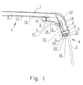
- Fig. 1 shows the upper portion of a vehicle and shows that Roof plate 1 and the adjoining side panel 2.
- Zum Vehicle body includes crossbars or hoops 3, on which the roof panel 1 and supports longitudinal bars 4 and 5 as the upper limit of a window opening and for supporting a windowpane, here as a large panoramic window 6 is formed.
- each two cladding profiles namely an upper cladding profile 9 and a lower cladding profile 10 arranged, the vehicle ceiling 7 in cooperation with a Ceiling panel 11 give a particularly attractive appearance.
- the Cladding profiles 9 and 10 are each of two carrier profiles 12 and 13, of which the first 12 on the hoops 3 and the second 13 at a belonging to the body structure adapter element 14 is fixed.
- the arrangement of the trim profiles 9 and 10 is such that two longitudinal edge portions thereof to form a first gap opening 15 overlap and between the top edge of the trim profile 9 and the vehicle roof or the ceiling panel 11 a second Gap opening 16 is formed. Furthermore, the arrangement of the cladding profiles 9 and 10 made so that they from the adjacent vehicle body structure are spaced, so that here an air channel 17 results. As Air outlet for a vehicle permanent ventilation serve the stomata 15 and 16, which thus fulfill an air-flow function.
- the lower fairing profile 10 has an adjacent vehicle side wall 8 outwardly directed collar 18 with a formed therein undercut receiving groove 19, for example, for receiving a Sun protection device such as a roller blind, not shown.
- a Sun protection device such as a roller blind
- Air duct 20 with an air outlet gap 21 is used.
- the air supply in the air duct 17 and / or 20 via conventional means whose further explanation is unnecessary.
- FIG. 2 shows, on an enlarged scale, the system area A according to FIG Arrangement of the carrier profile 12 on the hoops 3 and the determination of the upper trim profile 9 on the carrier profile 12.
- the carrier profile 12 the preferably consists of the section of an aluminum extruded profile, is supported by a cantilevered leg 22 at the not shown here Deflect 3 and is at this z. B. fastened by means of threaded bolts 23.
- threaded bolts 23 In a thigh 22 facing away from the thickened head are threaded holes 24, whose purpose will be described and an input side narrowed receiving groove 25 is formed. Close to the receiving groove 25 there is a, at this right angle standing second receiving groove 26, from the upper boundary leg in an upward direction Support web 27 passes, which for supporting the ceiling trim 11th serves.
- the receiving groove 25 serves to define the trim profile 9, that, as well as the trim profile 10 is made of plastic, wherein should remain open, whether it is an extrusion or Injection molded part is.
- the trim profile 9 am upper end portion of a molded on the back resilient clip strip 28th with a on the input side narrowing of the receiving groove 25 supporting Latch 29 on.
- the trim profile 9 has a special feature in that it - like shown - consist of two parts and a separately manufactured tail 30 may have plastic, with a molded back Clip element 31, which can be inserted into the receiving groove 26 and latched here is. Between the carrier profile 12 and the clip element 31 of the tail 30, a relatively large support surface is provided for the purpose of warranty a reliable and especially wobble-free connection.
- the purpose of the two-part design of the trim profile 9 is in the possibility thus created a arranged on the support bar 29 lighting device 32 easily accessible.
- the lighting device 32 can supply the vehicle with room light, also over Continuous lines, provided that the end pieces 30 consist of transparent Abblendprofilen.
- Fig. 3 shows on an enlarged scale the system area B of Fig. 1, leaves the design of the carrier profile 13, the upper edge region of the Cladding profile 9 and the upper edge region of the lower cladding profile 10 recognize.
- the specified by the adapter element 14 Body adaptation is illustrated by the line 33.
- the carrier profile 13, which can be fixed by means of threaded bolts 34 on the adapter element 14 is has an upper receiving opening 35 for receiving and supporting of the lower edge region of the trim profile 9.
- the receiving opening 35 is plug-in side narrowed by webs 36, 37, so that for the upper trim profile 9 during assembly for the lower edge region a male / EingurenkMIS with respect to the receiving opening 35 and for the upper edge area a clip connection between the receiving groove 25 and the clip strip 28 together with locking lugs 29 results.
- the clip strip 40 has a rear lug 39 engaging behind Latch 41 on.
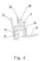
- Fig. 4 shows on an enlarged scale the system area (according to Fig. 1) and leaves a third, attached to the longitudinal spar 4 by means of threaded bolts 44
- Carrier profile 45 and the lower edge region of the trim profile 10 with the collar 18 and the receiving channel 19 recognize.
- the Montage is the lower marginal edge region of the trim profile 10 in the carrier profile recording 46 inserted and then the upper marginal edge region latched by pressing the clip strip 40 into the receiving groove 38.
- FIG. 4 also shows that collar 18 is not necessarily related to the trim profile 10 is integral, but also formed as a separate component may be that with the trim profile 10 via a plug-in / locking connection can be united.
- the collar 18 is, unlike the fairing profile 10 is not needed if instead of panoramic windows 6 smaller normal discs are provided.
- the Deckenverlies- and air duct system of FIG. 5 is in view that it is an essential concern of the present invention, to use standardized parts, with the above-described embodiment identical, but also supplemented by a further carrier profile 48, a supporting supplementary profile 49, a third cladding profile 50 and a Cover profile 51.
- the carrier profile 48 is, see. also in Fig. 6 in the enlarged Scale shown system area D of FIG. 5 on the vehicle body fixed and preferably consists of the section of an aluminum extruded profile.
- On the support section 48 sits by means of screws 52 thereto set the supplemental profile 49, which also preferably preferred
- the section of an aluminum extruded section is made to be a bearing Function to take over.
- the supplementary profile 49 the engages upper end in the receiving groove 19 of the trim profile 10, points underendig a similarly shaped receiving groove 53, and optionally for receiving a roller blind, not shown, or for receiving a at the top Edge region of the trim profile 50 molded Klipsang 54.
- a Rolloability in the form of an undercut receiving groove 55 is located here at the lower edge region of the cladding 50.
- Between the cladding profiles 10 and 50 is the cover profile formed of plastic 51 arranged and thereby on the supplementary profile 49 z. B. by a Clip holder fixed. This is the gap between the cladding profiles 10 and 50 closed in optically optimal manner.
- the invention consists, so far described from standard parts, the prefabricated and can be kept in stock. At best in order to adapt the length to the different types of vehicles (travel, mini or midi buses) or circumcision measures are required.
- the invention but in particular also makes it possible to modularly combine various components, wherein a modular structure z. B. for the carrier profiles 12 with the complete lighting device 32 and provided with the end pieces 30 may be, including extending between two support profiles 12 Ceiling covering 11.
- Fig. 7 in conjunction with the System area E performing Fig. 8 shows a solution with which the of FIG. 1 is completed by a total with the reference numeral 60 designated luggage rack is provided.
- the luggage rack 60 is held by supports 61 and the supports 61 are each one with a Hook 62 hooked into a receptacle of the support section 13 and the other with screws 63 in the threaded holes 24 of the support profile 12th are screwed in, held.
- the luggage tray 60 has a surface side Luggage tray 64 and in particular a hollow chamber profile with the particular advantage that the luggage rack 60 at the same time Main air channel 65 forms and with ventilation nozzles 66 for individual ventilation can be equipped.
- the individual chambers of the hollow chamber profile are connected through air vents, so that the entire Hollow chamber profile forms the main air channel 65.
- the hollow chamber profile of Luggage rack 60 may consist of a light metal extruded profile, wherein to the optical condition of the surfaces no special requirements are to be made, because by means of decorative profiles 67, 68 and 69 of the each desired aesthetic effect can be achieved easily.
- the decor profile 69 is also designed to accommodate so-called service sets, in addition to the mentioned ventilation nozzles 66 with lighting devices, Speakers, switches, control buttons and the like.
- the space between the hollow profile of the luggage rack 60 and the Vehicle side wall 8 or the panoramic window 6 may be with a tubular Filler 70 are bridged, it is recommended for fixing the filling piece 70 a supplementary profile 49, as with reference to FIG. 5 described.
- a handrail 71st z. B. attached via a Klipmontage.
- This handrail 71 encloses until on a gap opening 72 a cavity 73, which for receiving a Lighting device 74 is used.
- the filler 70 also by a handrail 71 corresponding Component to be replaced as a visually appealing conclusion, with or without a lighting device.
- Fig. 9 shows a solution with that of Fig. 5 is completed by the arrangement of a luggage rack 60.
- the luggage rack 60 corresponds in her Structure and in their arrangement exactly as described with reference to FIG. 7 Embodiment, so that here a repeated explanation not is required. It remains only to mention that the cover 51 after Fig. 5 is omitted, provided on the supplementary profile 49, a filler 70, as in Fig. 7 shown to come to the arrangement.
- the new ceiling cladding and air handling system for large vehicles captivates by the simplicity of its standard components, both in terms of their construction as well as in terms of their mountability. there is also the modular construction option particularly noteworthy.
- the standard elements come from the simplest to the most exclusive Embodiment used and it is up to the customer, whether a lighting device or a luggage rack are provided should, but the waiver of a luggage rack at the same time a waiver to an individual ventilation means.
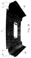
- FIG. 10 shows a perspective View of the embodiment of FIG. 5
- FIG. 11 is a perspective View of the embodiment of Fig. 7. It can be seen that in the Ceiling panel 11 a cutout 75 is provided for a roof hatch and that the floor of the luggage rack 60 or the decor profile 69 of the luggage rack 60 a series of openings 76 for the arrangement of not has shown service sets. From Fig. 10 it is also apparent that the luggage rack 60 can reach up to the vehicle side wall 8 (left side of the display) or from the vehicle side wall 8 by the arrangement of a Filler 70 may be spaced.
- Fig. 12 shows a vertical section through a large-capacity vehicle with a Deckenverdisposeds- and air control system as described above with reference to FIG. 5, the arrangement of the trim profiles 9, 10 and 50 in the transition areas from the vehicle ceiling to the vehicle side walls 8 is clearly visible.
- Fig. 13 shows the same vertical section as Fig. 12, but wherein the Deckenverdisposeds- and air duct system a relatively narrow luggage rack 60, above the Einsitzer #2, and through a relatively wide luggage rack 60, is added above the double seat row.
- the embodiment of FIG. 14 shows the same embodiment in FIG a equipped with panoramic windows 6 large capacity vehicle.
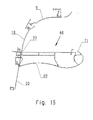
- FIG. 15 shows a hollow-chamber profile for a luggage rack 60 of small width, whose end piece 77 can be connected directly to the supplementary profile 49, for the rest, however, as well as each of the other luggage racks 60, too Supports 61 is worn.
- Fig. 14 are a dot-dash lines Decor profile 69 and embodiments of handrails 71 indicated.
- the Luggage rack according to Fig. 15 differs from the z. B. Fig. 7 alone thereby, that by omitting a hollow chamber, a smaller width having.
- Fig. 16 In vehicles with two double seat rows of Fig. 16 are the Ceiling cladding and air handling systems of both transitional areas of Vehicle roof to the vehicle side walls 8 including the luggage racks 60 usually formed identically.
- the invention is not limited to the illustrated and described embodiments but also includes all within the meaning of the invention equivalent designs. Furthermore, the invention is still so far not limited to the combination of features defined in claim 1, but can also be determined by any other combination of Be defined characteristics of all individually disclosed individual features. This means that basically every single feature of claim 1 omitted or by at least one elsewhere in the application documents disclosed individual feature can be replaced. Insofar is the Claim 1 merely as a first formulation attempt for an invention to understand.
Landscapes
- Mechanical Engineering (AREA)
- Engineering & Computer Science (AREA)
- Physics & Mathematics (AREA)
- Thermal Sciences (AREA)
- Vehicle Step Arrangements And Article Storage (AREA)
- Body Structure For Vehicles (AREA)
- Vehicle Interior And Exterior Ornaments, Soundproofing, And Insulation (AREA)
- Fittings On The Vehicle Exterior For Carrying Loads, And Devices For Holding Or Mounting Articles (AREA)
- Physical Vapour Deposition (AREA)
- Duct Arrangements (AREA)
- Rigid Pipes And Flexible Pipes (AREA)
- Application Of Or Painting With Fluid Materials (AREA)
- Protection Of Pipes Against Damage, Friction, And Corrosion (AREA)
Abstract
Description
- Fig. 1
- einen Übergangsbereich vom Fahrzeugdach zu einer Fahrzeugseitenwand eines Großraumfahrzeugs mit einer Standardsystemausrührung,
- Fig. 2
- eine vergrößerte Darstellung des in Fig. 1 strichpunktiert eingekreisten Systembereichs A,
- Fig. 3
- eine vergrößerte Darstellung des in Fig. 1 strichpunktiert eingekreisten Systembereichs B,
- Fig. 4
- eine vergrößerte Darstellung des in Fig. 1 strichpunktiert eingekreisten Systembereichs C,
- Fig. 5
- die Standard-Systemausführung nach Fig. 1 mit einer Systemerweiterung,
- Fig. 6
- eine vergrößerte Darstellung des in Fig. 5 strichpunktiert eingekreisten Systembereichs D,
- Fig. 7
- die Standard-Systemausrührung nach Fig. 1 mit einer Systemergänzung in Form einer Gepäckablage mit Hauptluftkanal,
- Fig. 8
- eine vergrößerte Darstellung des in Fig. 7 strichpunktiert eingekreisten Systembereichs E,
- Fig. 9
- die Systemausführung nach Fig. 5 mit einer Systemergänzung in Form einer Gepäckablage mit Hauptluftkanal,
- Fig. 10
- eine perspektivische Gesamtansicht der Systemausführung nach Fig. 1,
- Fig. 11
- eine perspektivische Gesamtansicht der Systemausführung nach Fig. 7,
- Fig. 12
- einen Vertikalschnitt durch ein Großraumfahrzeug mit einer Systemausführung nach Fig. 5,
- Fig. 13
- einen Vertikalschnitt durch ein Großraumfahrzeug mit einer Systemausführung nach Fig. 9,
- Fig. 14
- einen Vertikalschnitt durch ein Großraumfahrzeug mit einer Systemausführung nach Fig. 7,
- Fig. 15
- eine Einzelheit des Systems und
- Fig. 16
- einen Vertikalschnitt durch ein Großraumfahrzeug mit einer Systemausführung nach Fig. 7.
Claims (10)
- Deckenverkleidungs- und Luftleitsystem für Großraumfahrzeuge mit sich in Fahrzeuglängsrichtung jeweils im Übergangsbereich von der Fahrzeugdecke (7) zu den Fahrzeugseitenwänden (8) erstreckenden, am Fahrzeugaufbau befestigbaren Trägerprofilen (12, 13) und jeweils daran anordbaren Verkleidungsprofilen (9, 10), wobei in jedem Übergangsbereich jeweils zwei Verkleidungsprofile (9, 10) vorgesehen und derart an den Trägerprofilen (12, 13) angeordnet sind, dass sich die Längskantenbereiche der Verkleidungsprofile (9, 10) unter Bildung einer ersten Spaltöffnung (15) überlappen, wobei das in der Einbaulage obere Verkleidungsprofil (9) mit seiner oberen Randkante vom Fahrzeugdach oder einer darunter angeordneten Dachverkleidung (11) zwecks Bildung einer zweiten Spaltöffnung (16) beabstandet ist und wobei zwischen dem Fahrzeugaufbau und den Verkleidungsprofilen (9, 10) jeweils ein Luftkanal (17) ausgebildet ist.
- Deckenverkleidungs- und Luftleitsystem nach Anspruch 1, dadurch gekennzeichnet, dass die Verkleidungsprofile (9, 10) an den Trägerprofilen (12, 13) jeweils über Einschub- und/oder Einrenk- und/oder Einklipsverbindungen anordbar sind.
- Deckenverkleidungs- und Luftleitsystem nach Anspruch 1 oder 2, dadurch gekennzeichnet, dass das in der Einbaulage jeweils untere Verkleidungsprofil (10) einen zur benachbarten Fahrzeugseitenwand (8) hin ausgerichteten Kragen (18) mit einer darin ausgebildeten hinterschnittenen Aufnahmenut (19) zur wahlweisen Aufnahme eines Sonnenschutzrollos oder eines Teilbereichs eines Ergänzungsprofils (49) aufweist, wobei das Ergänzungsprofil (49) seinerseits zur Aufnahme eines Sonnenschutzrollos oder zur Halterung eines dritten Verkleidungsprofils (50) sowie eines Abdeckprofils (51) oder für die Abstützung einer Gepäckablage (60) vorgesehen ist.
- Deckenverkleidungs- und Luftleitsystem nach wenigstens einem der Ansprüche 1 bis 3, dadurch gekennzeichnet, dass das dritte Verkleidungsprofil (50) an seiner unteren Längskante eine hinterschnittene Aufnahmenut (55) für ein Sonnenschutzrolle aufweist.
- Deckenverkleidungs- und Luftleitsystem nach wenigstens einem der vorangegangenen Ansprüche, dadurch gekennzeichnet, dass dem System zumindest einer Seitenwand benachbart eine durchlaufende Gepäckablage (60) zugeordnet ist, welche im wesentlichen aus einem Hohlkammerprofil mit einer oberen, vom Fahrzeugdach beabstandeten Ablagefläche (64) besteht und von Stützen (61) getragen wird, die an den Trägerprofilen (12, 13) befestigbar sind.
- Deckenverkleidungs- und Luftleitsystem nach Anspruch 5, dadurch gekennzeichnet, dass das Hohlkammerprofil der Gepäckablage (60) als Luft- bzw. Hauptluftkanal (65) zur Luftversorgung von am Hohlkammerprofil unterseitig angeordneten Luftdüsen (66) ausgeführt ist.
- Deckenverkleidungs- und Luftleitsystem nach Anspruch 5 oder 6, dadurch gekennzeichnet, dass der Gepäckablage (60) ein Handlauf (71) zugeordnet ist.
- Deckenverkleidungs- und Luftleitsystem nach Anspruch 7, dadurch gekennzeichnet, dass innerhalb des Handlaufs (71) eine Beleuchtungseinrichtung (74) angeordnet ist, wobei eine Spaltöffnung (72) zwischen Handlauf (71) und Hohlkammerprofil oder eine Ausbildung des Handlaufs (71) aus lichtdurchlässigem Material als Lichtaustritt vorgesehen ist.
- Deckenverkleidungs- und Luftleitsystem nach zumindest einem der vorangegangenen Ansprüche, dadurch gekennzeichnet, dass die Trägerprofile (12, 13, 48) und Ergänzungsprofile (49) aus Abschnitten von Aluminiumstrangpressprofilen bestehen, während die Verkleidungsprofile (9, 10, 50) und Abdeckprofile (51) jeweils aus Kunststoff gebildet sind.
- Deckenverkleidungs- und Luftleitsystem nach zumindest einem der vorangegangenen Ansprüche, dadurch gekennzeichnet, dass zwischen dem Fahrzeugdach (1) oder einer darunter angeordneten Dachverkleidung (11) und dem oberen Verkleidungsprofil (9) eine Beleuchtungseinrichtung (32) zur Versorgung des Fahrzeugs mit Raumlicht angeordnet ist.
Applications Claiming Priority (2)
| Application Number | Priority Date | Filing Date | Title |
|---|---|---|---|
| DE10152659 | 2001-10-16 | ||
| DE10152659A DE10152659A1 (de) | 2001-10-16 | 2001-10-16 | Deckenverkleidungs- und Luftleitsystem |
Publications (4)
| Publication Number | Publication Date |
|---|---|
| EP1302369A2 true EP1302369A2 (de) | 2003-04-16 |
| EP1302369A8 EP1302369A8 (de) | 2003-06-25 |
| EP1302369A3 EP1302369A3 (de) | 2004-06-09 |
| EP1302369B1 EP1302369B1 (de) | 2005-07-20 |
Family
ID=7703668
Family Applications (1)
| Application Number | Title | Priority Date | Filing Date |
|---|---|---|---|
| EP02019402A Expired - Lifetime EP1302369B1 (de) | 2001-10-16 | 2002-08-30 | Deckenverkleidungs- und Luftleitsystem |
Country Status (6)
| Country | Link |
|---|---|
| EP (1) | EP1302369B1 (de) |
| AT (1) | ATE299813T1 (de) |
| DE (2) | DE10152659A1 (de) |
| ES (1) | ES2243632T3 (de) |
| PL (1) | PL356530A1 (de) |
| PT (1) | PT1302369E (de) |
Cited By (8)
| Publication number | Priority date | Publication date | Assignee | Title |
|---|---|---|---|---|
| EP1500576A3 (de) * | 2003-07-22 | 2005-08-17 | DaimlerChrysler AG | Deckenanordnung für Grossraumfahrzeug |
| WO2006032431A1 (en) * | 2004-09-20 | 2006-03-30 | Ellamp Interiors Spa | A versatile luggage rack construction |
| EP1702825A3 (de) * | 2005-03-17 | 2007-10-17 | Hitachi, Ltd. | Fahrgastkabine eines Schienenfahrzeuges |
| JP2012236497A (ja) * | 2011-05-11 | 2012-12-06 | Nippon Sharyo Seizo Kaisha Ltd | 鉄道車両の側天井構造 |
| DE102016122483A1 (de) | 2016-11-22 | 2018-05-24 | Bombardier Transportation Gmbh | Fahrzeug |
| PL422829A1 (pl) * | 2017-09-13 | 2019-03-25 | Pojazdy szynowe PESA Bydgoszcz Spółka Akcyjna | Wyłożenie ściany bocznej pojazdu |
| CN111071125A (zh) * | 2018-10-19 | 2020-04-28 | 郑州宇通客车股份有限公司 | 车辆及车辆行李架的扶手型材 |
| EP3812217A1 (de) * | 2019-10-22 | 2021-04-28 | MAGNA STEYR Fahrzeugtechnik AG & Co KG | Dachmodul |
Families Citing this family (3)
| Publication number | Priority date | Publication date | Assignee | Title |
|---|---|---|---|---|
| DE102005038759B4 (de) * | 2005-08-17 | 2008-05-15 | Audi Ag | Luftleitvorrichtung eines Fahrzeuges |
| CN110481273B (zh) * | 2019-08-29 | 2022-03-15 | 安徽安凯汽车股份有限公司 | 一种客车风道型材 |
| EP4183605A1 (de) * | 2021-11-23 | 2023-05-24 | Iveco Czech Republic A.S. | Verbesserter luftkanal für ein fahrzeug des öffentlichen personenverkehrs |
Family Cites Families (8)
| Publication number | Priority date | Publication date | Assignee | Title |
|---|---|---|---|---|
| DE7333031U (de) * | 1973-09-12 | 1974-01-03 | Gottlob Auwaerter Kg | Fahrzeugaufbau insbesondere fuer reiseomnibusse |
| DE2739253A1 (de) * | 1977-08-31 | 1979-03-15 | Kaessbohrer Fahrzeug Karl | Linien-omnibus |
| DE2927640A1 (de) * | 1979-07-09 | 1981-01-22 | Talbot Waggonfab | Innenverkleidung fuer den deckenbereich von fahrzeugen |
| DE3036546C2 (de) * | 1980-09-27 | 1986-04-30 | Daimler-Benz Ag, 7000 Stuttgart | Vorrichtung zum Belüften, Beheizen und/oder Kühlen von großen Fahrzeugräumen |
| DE3310051A1 (de) * | 1983-03-19 | 1984-09-27 | Daimler-Benz Ag, 7000 Stuttgart | Befestigung fuer flaechige verkleidungsteile, klappen od.dgl. insbesondere zur innenauskleidung von omnibussen |
| DE3333063C2 (de) * | 1983-09-14 | 1987-04-30 | Daimler-Benz Ag, 7000 Stuttgart | Federnde Halteklammer mit etwa U-förmigem Profil |
| DE3530533A1 (de) * | 1985-08-27 | 1987-03-12 | Daimler Benz Ag | Innenausgestaltung des dachbereiches von omnibussen |
| DE19746795A1 (de) * | 1997-10-23 | 1999-04-29 | Duewag Ag | Innenverkleidung für den Deckenbereich eines großräumigen Fahrzeuges zur Personenbeförderung |
-
2001
- 2001-10-16 DE DE10152659A patent/DE10152659A1/de not_active Withdrawn
-
2002
- 2002-08-30 AT AT02019402T patent/ATE299813T1/de not_active IP Right Cessation
- 2002-08-30 ES ES02019402T patent/ES2243632T3/es not_active Expired - Lifetime
- 2002-08-30 PT PT02019402T patent/PT1302369E/pt unknown
- 2002-08-30 EP EP02019402A patent/EP1302369B1/de not_active Expired - Lifetime
- 2002-08-30 DE DE50203666T patent/DE50203666D1/de not_active Expired - Fee Related
- 2002-10-08 PL PL02356530A patent/PL356530A1/xx not_active IP Right Cessation
Cited By (9)
| Publication number | Priority date | Publication date | Assignee | Title |
|---|---|---|---|---|
| EP1500576A3 (de) * | 2003-07-22 | 2005-08-17 | DaimlerChrysler AG | Deckenanordnung für Grossraumfahrzeug |
| WO2006032431A1 (en) * | 2004-09-20 | 2006-03-30 | Ellamp Interiors Spa | A versatile luggage rack construction |
| EP1702825A3 (de) * | 2005-03-17 | 2007-10-17 | Hitachi, Ltd. | Fahrgastkabine eines Schienenfahrzeuges |
| JP2012236497A (ja) * | 2011-05-11 | 2012-12-06 | Nippon Sharyo Seizo Kaisha Ltd | 鉄道車両の側天井構造 |
| DE102016122483A1 (de) | 2016-11-22 | 2018-05-24 | Bombardier Transportation Gmbh | Fahrzeug |
| PL422829A1 (pl) * | 2017-09-13 | 2019-03-25 | Pojazdy szynowe PESA Bydgoszcz Spółka Akcyjna | Wyłożenie ściany bocznej pojazdu |
| CN111071125A (zh) * | 2018-10-19 | 2020-04-28 | 郑州宇通客车股份有限公司 | 车辆及车辆行李架的扶手型材 |
| CN111071125B (zh) * | 2018-10-19 | 2023-10-03 | 宇通客车股份有限公司 | 车辆及车辆行李架的扶手型材 |
| EP3812217A1 (de) * | 2019-10-22 | 2021-04-28 | MAGNA STEYR Fahrzeugtechnik AG & Co KG | Dachmodul |
Also Published As
| Publication number | Publication date |
|---|---|
| ES2243632T3 (es) | 2005-12-01 |
| EP1302369A3 (de) | 2004-06-09 |
| EP1302369A8 (de) | 2003-06-25 |
| DE10152659A1 (de) | 2003-04-17 |
| EP1302369B1 (de) | 2005-07-20 |
| PL356530A1 (en) | 2003-04-22 |
| DE50203666D1 (de) | 2005-08-25 |
| PT1302369E (pt) | 2005-10-31 |
| ATE299813T1 (de) | 2005-08-15 |
Similar Documents
| Publication | Publication Date | Title |
|---|---|---|
| DE29920487U1 (de) | Fahrzeuginnenraumbeleuchtung | |
| DE19752989B4 (de) | Seitenairbag-Vorrichtung | |
| DE19531876A1 (de) | Querträger für die Befestigung des Armaturenbrettes | |
| EP1302369B1 (de) | Deckenverkleidungs- und Luftleitsystem | |
| DE10219053A1 (de) | Belüftungseinrichtung | |
| DE4128234C1 (de) | ||
| DE29719025U1 (de) | Beleuchtungssystem für einen Personenkraftwagen | |
| EP0524397A1 (de) | Modulares Gepäcksicherungssystem | |
| DE102006009629A1 (de) | Deckensystem für Grossraumfahrzeuge oder -flugzeuge | |
| EP2335992A1 (de) | Modularer Fahrerstand für Schienenfahrzeuge und Verfahren zur Herstellung | |
| EP3386834B1 (de) | Gepäckablagenmodul zum aufbau einer gepäckablage in einem schienenfahrzeug | |
| DE7333031U (de) | Fahrzeugaufbau insbesondere fuer reiseomnibusse | |
| DE19644155B4 (de) | Kraftfahrzeugtür mit Türaußenblech, Türinnenblech und Bauteilträger für das Türschloß | |
| DE102006014719B4 (de) | Trägerprofil und Befestigungsanordnung eines Sitzuntergestells an einer Bodenanlage eines Omnibusses | |
| DE102007056168A1 (de) | Anordnung zum Verkleiden von Fahrzeuginnenräumen | |
| EP0972661B1 (de) | Luftkanal für Grossraumfahrzeuge | |
| DE20016392U1 (de) | Modulares Dachsystem für Omnibusse | |
| DE4431245C1 (de) | Deckenkanalanordnung für Großraumfahrzeuge | |
| DE4121013A1 (de) | Verkleidung fuer eine fenster- oder tuersaeule eines kraftfahrzeuges | |
| DE822656C (de) | Kastenwagen mit mehr als einer Sitzreihe fuer Mitfahrer | |
| DE19751671B4 (de) | Trennwand für ein Kraftfahrzeug | |
| DE60003256T2 (de) | Verkleidungsanordnung für einen Kraftfahrzeugblechteil | |
| DE10202169C1 (de) | Schalttafelanordnung für ein Kraftfahrzeug | |
| WO2007062638A1 (de) | Fahrzeugdach mit einer dachhaut und wenigstens einer dachstrebe zur stabilisierung der dachhaut | |
| EP0753452A1 (de) | Innenausbau-Element für Fahrzeuge insbesondere für Eisenbahnwaggons |
Legal Events
| Date | Code | Title | Description |
|---|---|---|---|
| PUAI | Public reference made under article 153(3) epc to a published international application that has entered the european phase |
Free format text: ORIGINAL CODE: 0009012 |
|
| AK | Designated contracting states |
Designated state(s): AT BE BG CH CY CZ DE DK EE ES FI FR GB GR IE IT LI LU MC NL PT SE SK TR |
|
| AX | Request for extension of the european patent |
Extension state: AL LT LV MK RO SI |
|
| RTI1 | Title (correction) |
Free format text: ROOF LINER AND AIR DUCT SYSTEM |
|
| PUAL | Search report despatched |
Free format text: ORIGINAL CODE: 0009013 |
|
| AK | Designated contracting states |
Kind code of ref document: A3 Designated state(s): AT BE BG CH CY CZ DE DK EE ES FI FR GB GR IE IT LI LU MC NL PT SE SK TR |
|
| AX | Request for extension of the european patent |
Extension state: AL LT LV MK RO SI |
|
| RIC1 | Information provided on ipc code assigned before grant |
Ipc: 7B 60R 13/02 A Ipc: 7B 60H 1/00 B Ipc: 7B 60R 5/00 B |
|
| 17P | Request for examination filed |
Effective date: 20040604 |
|
| RAP1 | Party data changed (applicant data changed or rights of an application transferred) |
Owner name: HAPPICH INTERIORS GMBH |
|
| 17Q | First examination report despatched |
Effective date: 20040908 |
|
| GRAP | Despatch of communication of intention to grant a patent |
Free format text: ORIGINAL CODE: EPIDOSNIGR1 |
|
| AKX | Designation fees paid |
Designated state(s): AT BE BG CH CY CZ DE DK EE ES FI FR GB GR IE IT LI LU MC NL PT SE SK TR |
|
| GRAS | Grant fee paid |
Free format text: ORIGINAL CODE: EPIDOSNIGR3 |
|
| GRAA | (expected) grant |
Free format text: ORIGINAL CODE: 0009210 |
|
| AK | Designated contracting states |
Kind code of ref document: B1 Designated state(s): AT BE BG CH CY CZ DE DK EE ES FI FR GB GR IE IT LI LU MC NL PT SE SK TR |
|
| PG25 | Lapsed in a contracting state [announced via postgrant information from national office to epo] |
Ref country code: FI Free format text: LAPSE BECAUSE OF FAILURE TO SUBMIT A TRANSLATION OF THE DESCRIPTION OR TO PAY THE FEE WITHIN THE PRESCRIBED TIME-LIMIT Effective date: 20050720 Ref country code: EE Free format text: LAPSE BECAUSE OF FAILURE TO SUBMIT A TRANSLATION OF THE DESCRIPTION OR TO PAY THE FEE WITHIN THE PRESCRIBED TIME-LIMIT Effective date: 20050720 Ref country code: IE Free format text: LAPSE BECAUSE OF FAILURE TO SUBMIT A TRANSLATION OF THE DESCRIPTION OR TO PAY THE FEE WITHIN THE PRESCRIBED TIME-LIMIT Effective date: 20050720 Ref country code: SK Free format text: LAPSE BECAUSE OF FAILURE TO SUBMIT A TRANSLATION OF THE DESCRIPTION OR TO PAY THE FEE WITHIN THE PRESCRIBED TIME-LIMIT Effective date: 20050720 Ref country code: CZ Free format text: LAPSE BECAUSE OF FAILURE TO SUBMIT A TRANSLATION OF THE DESCRIPTION OR TO PAY THE FEE WITHIN THE PRESCRIBED TIME-LIMIT Effective date: 20050720 |
|
| REG | Reference to a national code |
Ref country code: GB Ref legal event code: FG4D |
|
| REG | Reference to a national code |
Ref country code: CH Ref legal event code: EP |
|
| REG | Reference to a national code |
Ref country code: GB Ref legal event code: ERR Free format text: NOTIFICATION HAS BEEN RECEIVED FROM THE EUROPEAN PATENT OFFICE THAT IT WAS PUBLISHED IN GERMAN |
|
| REG | Reference to a national code |
Ref country code: IE Ref legal event code: FG4D Free format text: LANGUAGE OF EP DOCUMENT: GERMAN |
|
| REF | Corresponds to: |
Ref document number: 50203666 Country of ref document: DE Date of ref document: 20050825 Kind code of ref document: P |
|
| PG25 | Lapsed in a contracting state [announced via postgrant information from national office to epo] |
Ref country code: CY Free format text: LAPSE BECAUSE OF FAILURE TO SUBMIT A TRANSLATION OF THE DESCRIPTION OR TO PAY THE FEE WITHIN THE PRESCRIBED TIME-LIMIT Effective date: 20050830 Ref country code: AT Free format text: LAPSE BECAUSE OF NON-PAYMENT OF DUE FEES Effective date: 20050830 |
|
| PG25 | Lapsed in a contracting state [announced via postgrant information from national office to epo] |
Ref country code: MC Free format text: LAPSE BECAUSE OF NON-PAYMENT OF DUE FEES Effective date: 20050831 Ref country code: BE Free format text: LAPSE BECAUSE OF NON-PAYMENT OF DUE FEES Effective date: 20050831 |
|
| PG25 | Lapsed in a contracting state [announced via postgrant information from national office to epo] |
Ref country code: LU Free format text: LAPSE BECAUSE OF NON-PAYMENT OF DUE FEES Effective date: 20050920 |
|
| GBT | Gb: translation of ep patent filed (gb section 77(6)(a)/1977) |
Effective date: 20050915 |
|
| PG25 | Lapsed in a contracting state [announced via postgrant information from national office to epo] |
Ref country code: GR Free format text: LAPSE BECAUSE OF FAILURE TO SUBMIT A TRANSLATION OF THE DESCRIPTION OR TO PAY THE FEE WITHIN THE PRESCRIBED TIME-LIMIT Effective date: 20051020 Ref country code: BG Free format text: LAPSE BECAUSE OF FAILURE TO SUBMIT A TRANSLATION OF THE DESCRIPTION OR TO PAY THE FEE WITHIN THE PRESCRIBED TIME-LIMIT Effective date: 20051020 Ref country code: DK Free format text: LAPSE BECAUSE OF FAILURE TO SUBMIT A TRANSLATION OF THE DESCRIPTION OR TO PAY THE FEE WITHIN THE PRESCRIBED TIME-LIMIT Effective date: 20051020 Ref country code: SE Free format text: LAPSE BECAUSE OF FAILURE TO SUBMIT A TRANSLATION OF THE DESCRIPTION OR TO PAY THE FEE WITHIN THE PRESCRIBED TIME-LIMIT Effective date: 20051020 |
|
| REG | Reference to a national code |
Ref country code: PT Ref legal event code: SC4A Effective date: 20050824 |
|
| REG | Reference to a national code |
Ref country code: ES Ref legal event code: FG2A Ref document number: 2243632 Country of ref document: ES Kind code of ref document: T3 |
|
| REG | Reference to a national code |
Ref country code: IE Ref legal event code: FD4D |
|
| ET | Fr: translation filed | ||
| PLBE | No opposition filed within time limit |
Free format text: ORIGINAL CODE: 0009261 |
|
| STAA | Information on the status of an ep patent application or granted ep patent |
Free format text: STATUS: NO OPPOSITION FILED WITHIN TIME LIMIT |
|
| 26N | No opposition filed |
Effective date: 20060421 |
|
| PG25 | Lapsed in a contracting state [announced via postgrant information from national office to epo] |
Ref country code: LI Free format text: LAPSE BECAUSE OF NON-PAYMENT OF DUE FEES Effective date: 20060831 Ref country code: CH Free format text: LAPSE BECAUSE OF NON-PAYMENT OF DUE FEES Effective date: 20060831 |
|
| REG | Reference to a national code |
Ref country code: CH Ref legal event code: PL |
|
| BERE | Be: lapsed |
Owner name: HAPPICH INTERIORS G.M.B.H. Effective date: 20050831 |
|
| NLS | Nl: assignments of ep-patents |
Owner name: HAPPICH FAHRZEUG- UND INDUSTRIETEILE GMBH Effective date: 20080616 |
|
| REG | Reference to a national code |
Ref country code: PT Ref legal event code: PC4A Owner name: HAPPICH FAHRZEUG- UND INDUSTRIETEILE GMBH, DE Effective date: 20080911 |
|
| PGFP | Annual fee paid to national office [announced via postgrant information from national office to epo] |
Ref country code: DE Payment date: 20080731 Year of fee payment: 7 Ref country code: ES Payment date: 20080811 Year of fee payment: 7 Ref country code: NL Payment date: 20080718 Year of fee payment: 7 Ref country code: PT Payment date: 20080723 Year of fee payment: 7 |
|
| PGFP | Annual fee paid to national office [announced via postgrant information from national office to epo] |
Ref country code: FR Payment date: 20080714 Year of fee payment: 7 Ref country code: IT Payment date: 20080731 Year of fee payment: 7 |
|
| PGFP | Annual fee paid to national office [announced via postgrant information from national office to epo] |
Ref country code: GB Payment date: 20080722 Year of fee payment: 7 |
|
| PGFP | Annual fee paid to national office [announced via postgrant information from national office to epo] |
Ref country code: TR Payment date: 20080724 Year of fee payment: 7 |
|
| REG | Reference to a national code |
Ref country code: PT Ref legal event code: MM4A Free format text: LAPSE DUE TO NON-PAYMENT OF FEES Effective date: 20100301 |
|
| REG | Reference to a national code |
Ref country code: NL Ref legal event code: V1 Effective date: 20100301 |
|
| GBPC | Gb: european patent ceased through non-payment of renewal fee |
Effective date: 20090830 |
|
| PG25 | Lapsed in a contracting state [announced via postgrant information from national office to epo] |
Ref country code: PT Free format text: LAPSE BECAUSE OF NON-PAYMENT OF DUE FEES Effective date: 20100301 |
|
| REG | Reference to a national code |
Ref country code: FR Ref legal event code: ST Effective date: 20100430 |
|
| PG25 | Lapsed in a contracting state [announced via postgrant information from national office to epo] |
Ref country code: DE Free format text: LAPSE BECAUSE OF NON-PAYMENT OF DUE FEES Effective date: 20100302 Ref country code: NL Free format text: LAPSE BECAUSE OF NON-PAYMENT OF DUE FEES Effective date: 20100301 Ref country code: FR Free format text: LAPSE BECAUSE OF NON-PAYMENT OF DUE FEES Effective date: 20090831 |
|
| REG | Reference to a national code |
Ref country code: ES Ref legal event code: FD2A Effective date: 20090831 |
|
| PG25 | Lapsed in a contracting state [announced via postgrant information from national office to epo] |
Ref country code: GB Free format text: LAPSE BECAUSE OF NON-PAYMENT OF DUE FEES Effective date: 20090830 |
|
| PG25 | Lapsed in a contracting state [announced via postgrant information from national office to epo] |
Ref country code: IT Free format text: LAPSE BECAUSE OF NON-PAYMENT OF DUE FEES Effective date: 20090830 |
|
| PG25 | Lapsed in a contracting state [announced via postgrant information from national office to epo] |
Ref country code: ES Free format text: LAPSE BECAUSE OF NON-PAYMENT OF DUE FEES Effective date: 20090831 |
|
| PG25 | Lapsed in a contracting state [announced via postgrant information from national office to epo] |
Ref country code: TR Free format text: LAPSE BECAUSE OF NON-PAYMENT OF DUE FEES Effective date: 20090830 |