EP4183605A1 - Verbesserter luftkanal für ein fahrzeug des öffentlichen personenverkehrs - Google Patents
Verbesserter luftkanal für ein fahrzeug des öffentlichen personenverkehrs Download PDFInfo
- Publication number
- EP4183605A1 EP4183605A1 EP22208513.6A EP22208513A EP4183605A1 EP 4183605 A1 EP4183605 A1 EP 4183605A1 EP 22208513 A EP22208513 A EP 22208513A EP 4183605 A1 EP4183605 A1 EP 4183605A1
- Authority
- EP
- European Patent Office
- Prior art keywords
- vehicle
- cover
- vehicle according
- fixing portion
- space
- Prior art date
- Legal status (The legal status is an assumption and is not a legal conclusion. Google has not performed a legal analysis and makes no representation as to the accuracy of the status listed.)
- Pending
Links
- 230000008878 coupling Effects 0.000 claims description 24
- 238000010168 coupling process Methods 0.000 claims description 24
- 238000005859 coupling reaction Methods 0.000 claims description 24
- 230000003750 conditioning effect Effects 0.000 claims description 7
- 239000000463 material Substances 0.000 claims description 4
- 238000004891 communication Methods 0.000 claims description 3
- 239000003365 glass fiber Substances 0.000 claims description 2
- 229910052751 metal Inorganic materials 0.000 claims description 2
- 239000002184 metal Substances 0.000 claims description 2
- 230000036316 preload Effects 0.000 claims description 2
- 230000000295 complement effect Effects 0.000 claims 1
- 238000009826 distribution Methods 0.000 description 3
- 239000012530 fluid Substances 0.000 description 3
- 238000007689 inspection Methods 0.000 description 3
- 238000004519 manufacturing process Methods 0.000 description 3
- 238000004378 air conditioning Methods 0.000 description 2
- 238000005553 drilling Methods 0.000 description 2
- 239000004593 Epoxy Substances 0.000 description 1
- 229910052782 aluminium Inorganic materials 0.000 description 1
- XAGFODPZIPBFFR-UHFFFAOYSA-N aluminium Chemical compound [Al] XAGFODPZIPBFFR-UHFFFAOYSA-N 0.000 description 1
- 238000004140 cleaning Methods 0.000 description 1
- 238000005520 cutting process Methods 0.000 description 1
- 238000013461 design Methods 0.000 description 1
- 238000001125 extrusion Methods 0.000 description 1
- 238000010438 heat treatment Methods 0.000 description 1
- 238000003780 insertion Methods 0.000 description 1
- 230000037431 insertion Effects 0.000 description 1
- 238000003754 machining Methods 0.000 description 1
- 238000012423 maintenance Methods 0.000 description 1
- 238000012986 modification Methods 0.000 description 1
- 230000004048 modification Effects 0.000 description 1
- 229920001567 vinyl ester resin Polymers 0.000 description 1
Images

Classifications
-
- B—PERFORMING OPERATIONS; TRANSPORTING
- B60—VEHICLES IN GENERAL
- B60H—ARRANGEMENTS OF HEATING, COOLING, VENTILATING OR OTHER AIR-TREATING DEVICES SPECIALLY ADAPTED FOR PASSENGER OR GOODS SPACES OF VEHICLES
- B60H1/00—Heating, cooling or ventilating [HVAC] devices
- B60H1/00507—Details, e.g. mounting arrangements, desaeration devices
- B60H1/00557—Details of ducts or cables
- B60H1/00564—Details of ducts or cables of air ducts
-
- B—PERFORMING OPERATIONS; TRANSPORTING
- B60—VEHICLES IN GENERAL
- B60H—ARRANGEMENTS OF HEATING, COOLING, VENTILATING OR OTHER AIR-TREATING DEVICES SPECIALLY ADAPTED FOR PASSENGER OR GOODS SPACES OF VEHICLES
- B60H1/00—Heating, cooling or ventilating [HVAC] devices
- B60H1/00357—Air-conditioning arrangements specially adapted for particular vehicles
- B60H1/00371—Air-conditioning arrangements specially adapted for particular vehicles for vehicles carrying large numbers of passengers, e.g. buses
Definitions
- the present invention concerns an air channel, in particular an air channel for a public transport vehicle.
- the present invention finds its preferred, although not exclusive, application in a bus.
- Public transport vehicles such as buses may comprise conditioning air apparatus configured to regulate the temperature of the space voted to house passengers.
- buses are at least provided with heating means configured to supply within the passenger space a delivery flow of heated air for providing a comfortable temperature in colder days such as in autumn or winter.
- the above conditioning means usually provides a flow of air having a delivery temperature set to vary the temperature in the passenger space to a target temperature.
- Such delivery air flow is provided to air channels configured to guide the air flow within at least part of the extension of the vehicle and to uniformly distribute the latter within said space.
- Existing air channels are usually constituted by molded profiled elements that comprises a plurality of holes. Clearly the holes are provided by drilling and/or cutting. Therefore, such operation is long and increases the cost of manufacturing the vehicle.
- fixation of such air channel is achieved by threaded elements that fix extremity portions of the air channels to the vehicle wall. Clearly such fixation increases inspection time for cleaning these later.
- An aim of the present invention is to satisfy the above mentioned needs in a cost-effective and optimized manner.
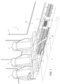
- Figure 1 discloses a portion of a public transport vehicle 1, such as a bus, comprising a plurality of walls 2 configured to delimit an inner space 3 suitable for housing a plurality of passengers.
- the walls 2 comprises a plurality of lateral walls 2a, a floor 2b and a ceiling (not shown).
- the vehicle 1, as known, comprises a plurality of seats 4 that fixedly carried by the vehicle's walls 2.
- the seats 4 are carried by the lateral wall 2a thanks to an inclined support leg 5.
- each leg 5 may support only one or a pair of seats 4.
- Vehicle 1 further comprises air conditioning means 6 that are configured to aspire an airflow from the space 3, vary its temperature and/or humidity and provide a delivery airflow within the space 3 to modify the temperature and/or humidity therein.
- Vehicle 1 further comprise at least an air channel 7 that is fluidly connected to air conditioning means 6 and configured to guide the delivery airflow along space 3.
- the air channel 7 extends parallel to a longitudinal axis A of the vehicle 1, on at least part thereof.
- the air channel 7 is carried by lateral wall 2a in a position to be vertically comprised between the leg 5 and the seat 4.
- the air channel 7 comprise a fixing portion 8 configured to be fixed to the wall 2 of the vehicle, i.e. to lateral wall 2a in the present embodiment, and a cover portion 9 configured to be selectively fixed to the fixing portion 8 to define air passages as defined in the following.
- the fixing portion 8 essentially comprise a fixing plate 8b configured to be fixed to the wall 2 of the vehicle and a support portion 8a configured to extend from the fixing plate 8b.
- the support portion 8a extends along an axis B that is preferably perpendicular to longitudinal axis A.
- the fixing portion 8 is therefore a profiled element.
- the fixing plate 8b may be fixed to the wall 2 of the vehicle via mechanical connection means, such as threaded means, or glued thereon.
- the support portion 8a extends from the middle of the fixing plate 8b, i.e. the fixing plate 8b extends equally along axis A from one side and the other of the support portion 8a. More preferably, the fixing portion 8 has a symmetrical shape about axis B.
- the support portion 8a comprises a pair of cantilevered walls 8a' extending along axis B and preferably parallel to this latter and a top wall 8a" configured to joint connect together the cantilevered walls 8a'.
- the top wall 8a" is preferably parallel to fixing plate 8b.
- the fixing portion 8 further comprises a plurality of coupling portions 8c configured to allow the connection of cover portions 9.
- the coupling portions 8c are preferably placed in a symmetric way with respect to axis B and at least two coupling portions 8c are provided for each side with respect to axis B.
- two coupling portions 8c are provided for each side of the fixing portion 8.
- a pair of coupling portions 8c is carried by the support portion 8a and a pair of coupling portions 8c is carried by the fixing plate 8b.
- the coupling portions 8c carried by the support portion 8a are fixed in the corner between the cantilevered walls 8a' and the top wall 8a"; the coupling portions 8c carried by the fixing plate 8b are fixed in extremity portions along axis A of the fixing plate 8b.
- the coupling portion 8c comprises a link portion 8c' configured to be connected to the relative element to which they are connected and a seat potion 8c" configured to cooperate at contact with the cover portion 9 to allow its coupling to the fixing portion 8.
- the fixing portion 8 is realized as one piece, i.e. monolithic, and preferably realized in metal, such as aluminum.
- the cover portion 9 comprises a cover plate 9a, preferably having a curved shape; in the disclosed exemplarily embodiment the cover plate 9a has a convex shape towards the space 3.
- the cover portion 9 comprises a pair cover element 9', 9" that are one separate with respect to the other and that are independently fixed to the fixing portion 8b.
- the cover portion 9 further comprises a coupling portion 9b that extends from the cover plate 9a on the side opposite to the one faced to space 3 and configured to cooperate at contact with the coupling portion 8c of the fixing portion 8.
- the coupling portion 9b comprises, similarly to the coupling portion 8c, a link portion 9b' configured to be connected to the cover element and a plug portion 9b" configured to cooperate at contact with fixing portion 8 as follows.
- the plug portion 9b" and the seat portion 8c" have a spherical shape.
- the plug portion 9b" has a diameter that is greater with respect to the seat portion 8c" thereby allowing their insertion therein with a preset preload that avoid any unwanted uncoupling of the cover from the fixing portion.
- each cover plate 9', 9" comprises a pair of coupling portions 9b configured to cooperate with the respective coupling portions 8c carried by fixing portion 8.
- the plug portion 9b" when inserted in the seat portion 8c" defines a hinge connection.
- the presence of two coupling portions 9b/8c allows, when connected, to lock the respective cover element 9', 9" to the fixing portion 8 and, when only one of such two coupling portions 9b/8c is connected, allows a rotation of the cover element 9', 9" thereon.
- each cover element 9', 9" is realized as one piece, i.e. monolithic, and preferably in polymeric material such as Vinylester, PA or epoxy; more preferably such polymeric material can be reinforced by glass fibers.
- the cover elements 9', 9" when coupled to the fixing portion 8 define with respect to this latter and wall 2 of the vehicle respective spaces 11, 12. At least one of such spaces 12 is in fluid communication with space 3.
- the cover elements 9', 9" defines first spaces 11 isolated with respect to the space 3 that are comprised by cover plate 9a of each cover element 9', 9", part of the fixing plate 8b and one of the cantilevered portions 8a' of the support portion 8a. Furthermore, the cover elements 9', 9'' defines second spaces 12, in fluid communication with space 3. One of such spaces 12 is comprised by terminal portions of the two cover elements 9', 9" and the top wall 8a" of the support portion 8a, two over spaces 12 are comprised between each of the cover elements 9', 9", the wall 2a and a terminal portion of the fixing plate 8b.
- cover plates 9a of each cover elements 9', 9" is designed so that they are distanced thereby providing a passage positioned above the top wall 8a" of the support portion 8a along direction of axis B and to not touch the wall 2a thereby providing a passage there between.
- the second spaces 12 fluidly communicates with space 3 via such passages realized by the extension of the cover plates 9a of each cover element 9', 9".
- the passage section of such passages may vary along axis A, e.g. having a smaller passage section in proximity of conditioning means 6 and a greater passage section on the farthest position in order to optimize the fluid distribution along longitudinal axis A of the vehicle.
- delivery air flow is provided by conditioning means 6 within the channel 7, in particular to second spaces 12.
- the delivery air flow flows along direction A and passes via passages between the cover plates 9a or the cover plate 9a the wall 2a in the space 3.
- the dimension of passages can be design in function of the flow quantity in order to allow a correct distribution of the delivery air flow, as said above.
- the air channel 7 is closed by a head portion so that the air passes via the above described distribution.
- the disassembling operation is the inverse of the above described.
- the shape and the number of couplings between the cover portions 9 and the fixing portion 8 allows to maintain each cover element 9', 9" fixed to the fixing portion 8 during the ride of the vehicle and the use of the conditioning means 6.
- the proposed system is very economic and of easy manufacturing with respect to known system. Indeed, it comprises elements that may be realized entirely by extrusion without need of machining or drilling.
- the proposed system allows a very quick assembly and disassembly of the cover elements on the respective support. Accordingly, the maintenance and inspection time is reduced.
- the proposed coupling between the cover elements and the support portion allows a very stable coupling that avoids any unwanted disassembly during the travel of the vehicle.
- the proposed symmetric shape of the fixing portion allows to use only half of this latter in case of reduced dimension for housing the air channel.
- the same element can be used for different typology of vehicles; clearly in such occurrence only a single cover element is present.
- shape or number of the described cover portions 9, fixing portion 8 or of coupling portions 8c/9b may vary according to the dimension of the vehicle.
Landscapes
- Physics & Mathematics (AREA)
- Thermal Sciences (AREA)
- Engineering & Computer Science (AREA)
- Mechanical Engineering (AREA)
- Air-Conditioning For Vehicles (AREA)
Applications Claiming Priority (1)
| Application Number | Priority Date | Filing Date | Title |
|---|---|---|---|
| IT202100029624 | 2021-11-23 |
Publications (1)
| Publication Number | Publication Date |
|---|---|
| EP4183605A1 true EP4183605A1 (de) | 2023-05-24 |
Family
ID=79831081
Family Applications (1)
| Application Number | Title | Priority Date | Filing Date |
|---|---|---|---|
| EP22208513.6A Pending EP4183605A1 (de) | 2021-11-23 | 2022-11-21 | Verbesserter luftkanal für ein fahrzeug des öffentlichen personenverkehrs |
Country Status (1)
| Country | Link |
|---|---|
| EP (1) | EP4183605A1 (de) |
Citations (3)
| Publication number | Priority date | Publication date | Assignee | Title |
|---|---|---|---|---|
| US6416116B1 (en) * | 2000-02-03 | 2002-07-09 | New Flyer Industries Limited | Interior structure of a mass transit vehicle |
| DE10152659A1 (de) * | 2001-10-16 | 2003-04-17 | Happich Fahrzeug & Ind Teile | Deckenverkleidungs- und Luftleitsystem |
| DE102013002641A1 (de) * | 2013-02-15 | 2014-08-21 | Man Truck & Bus Ag | Dachvoutenvorrichtung für ein Fahrzeug |
-
2022
- 2022-11-21 EP EP22208513.6A patent/EP4183605A1/de active Pending
Patent Citations (3)
| Publication number | Priority date | Publication date | Assignee | Title |
|---|---|---|---|---|
| US6416116B1 (en) * | 2000-02-03 | 2002-07-09 | New Flyer Industries Limited | Interior structure of a mass transit vehicle |
| DE10152659A1 (de) * | 2001-10-16 | 2003-04-17 | Happich Fahrzeug & Ind Teile | Deckenverkleidungs- und Luftleitsystem |
| DE102013002641A1 (de) * | 2013-02-15 | 2014-08-21 | Man Truck & Bus Ag | Dachvoutenvorrichtung für ein Fahrzeug |
Similar Documents
| Publication | Publication Date | Title |
|---|---|---|
| US7478670B2 (en) | Modular system for a 1-to-4 zone climate control system for vehicles | |
| EP2881270B1 (de) | Kühlmittelverteiler für ein Hybrid- oder Elektrofahrzeug und Kühlmittelkreislauf mit einem Kühlmittelverteiler | |
| US10011362B2 (en) | Aircraft outer skin heat exchanger, aircraft cooling system and method for operating an aircraft outer skin heat exchanger | |
| JP4744061B2 (ja) | 商業用車輛、例えばバス用の加熱及び/又は空調装置 | |
| CN109863047A (zh) | 用于机动车的空气流出器和装配其的机动车 | |
| US9067683B2 (en) | Support structure for use in an air supply arrangement and service supply system comprising said type of support structure and method for configuration | |
| US8474513B2 (en) | Air-conditioning system, especially automotive air-conditioning system | |
| EP1040946A3 (de) | Kraftfahrzeugklimaanlage | |
| EP2021235A1 (de) | Leitungssystemanordnung in einem einen rumpf aufweisenden luft- oder raumfahrzeug | |
| US20080108293A1 (en) | Temperature door for a vehicle and heating, ventilation, and air conditioning system | |
| EP4183605A1 (de) | Verbesserter luftkanal für ein fahrzeug des öffentlichen personenverkehrs | |
| US9987919B2 (en) | Flap system for controlling a vehicle cooling system | |
| CN112984870A (zh) | 用于车辆的一体式冷却剂加热模块 | |
| US8919425B2 (en) | Flow control valve and heat exchanger equipped with same | |
| CN104417315A (zh) | 中央扶手箱结构 | |
| CN107031341B (zh) | 用于暖通空调的促进混和的温度门 | |
| EP3127774B1 (de) | In die karosseriedachprofile integriertes luftkanalsystem | |
| CN105722704A (zh) | 车辆用座椅空调装置 | |
| EP2896525B1 (de) | Dachklimaanlage für Busse | |
| US20080017366A1 (en) | Air-Conditioning System, Especially Automotive Air-Conditioning System | |
| EP3378685B1 (de) | Klimaanlage für ein öffentliches personenverkehrsfahrzeug | |
| CN114222674A (zh) | 用于汽车尤其是轿车的通风装置以及具有这种通风装置的汽车 | |
| US7147039B2 (en) | Air routing device for a motor vehicle air conditioning or heating system | |
| US20140024303A1 (en) | Air conditioning system for motor vehicle | |
| US11110775B2 (en) | Airflow turning device for HVAC system |
Legal Events
| Date | Code | Title | Description |
|---|---|---|---|
| PUAI | Public reference made under article 153(3) epc to a published international application that has entered the european phase |
Free format text: ORIGINAL CODE: 0009012 |
|
| STAA | Information on the status of an ep patent application or granted ep patent |
Free format text: STATUS: THE APPLICATION HAS BEEN PUBLISHED |
|
| AK | Designated contracting states |
Kind code of ref document: A1 Designated state(s): AL AT BE BG CH CY CZ DE DK EE ES FI FR GB GR HR HU IE IS IT LI LT LU LV MC ME MK MT NL NO PL PT RO RS SE SI SK SM TR |
|
| STAA | Information on the status of an ep patent application or granted ep patent |
Free format text: STATUS: REQUEST FOR EXAMINATION WAS MADE |
|
| 17P | Request for examination filed |
Effective date: 20231122 |
|
| RBV | Designated contracting states (corrected) |
Designated state(s): AL AT BE BG CH CY CZ DE DK EE ES FI FR GB GR HR HU IE IS IT LI LT LU LV MC ME MK MT NL NO PL PT RO RS SE SI SK SM TR |
|
| STAA | Information on the status of an ep patent application or granted ep patent |
Free format text: STATUS: EXAMINATION IS IN PROGRESS |
|
| 17Q | First examination report despatched |
Effective date: 20240130 |