EP1302292A1 - Verfahren zur Herstellung einer aufblasbaren vulkanisierten Dichtung - Google Patents
Verfahren zur Herstellung einer aufblasbaren vulkanisierten Dichtung Download PDFInfo
- Publication number
- EP1302292A1 EP1302292A1 EP02022957A EP02022957A EP1302292A1 EP 1302292 A1 EP1302292 A1 EP 1302292A1 EP 02022957 A EP02022957 A EP 02022957A EP 02022957 A EP02022957 A EP 02022957A EP 1302292 A1 EP1302292 A1 EP 1302292A1
- Authority
- EP
- European Patent Office
- Prior art keywords
- sealing
- blank
- vulcanized
- hollow chamber
- seal
- Prior art date
- Legal status (The legal status is an assumption and is not a legal conclusion. Google has not performed a legal analysis and makes no representation as to the accuracy of the status listed.)
- Granted
Links
Images

Classifications
-
- B—PERFORMING OPERATIONS; TRANSPORTING
- B29—WORKING OF PLASTICS; WORKING OF SUBSTANCES IN A PLASTIC STATE IN GENERAL
- B29C—SHAPING OR JOINING OF PLASTICS; SHAPING OF MATERIAL IN A PLASTIC STATE, NOT OTHERWISE PROVIDED FOR; AFTER-TREATMENT OF THE SHAPED PRODUCTS, e.g. REPAIRING
- B29C65/00—Joining or sealing of preformed parts, e.g. welding of plastics materials; Apparatus therefor
- B29C65/02—Joining or sealing of preformed parts, e.g. welding of plastics materials; Apparatus therefor by heating, with or without pressure
-
- B—PERFORMING OPERATIONS; TRANSPORTING
- B29—WORKING OF PLASTICS; WORKING OF SUBSTANCES IN A PLASTIC STATE IN GENERAL
- B29C—SHAPING OR JOINING OF PLASTICS; SHAPING OF MATERIAL IN A PLASTIC STATE, NOT OTHERWISE PROVIDED FOR; AFTER-TREATMENT OF THE SHAPED PRODUCTS, e.g. REPAIRING
- B29C66/00—General aspects of processes or apparatus for joining preformed parts
- B29C66/50—General aspects of joining tubular articles; General aspects of joining long products, i.e. bars or profiled elements; General aspects of joining single elements to tubular articles, hollow articles or bars; General aspects of joining several hollow-preforms to form hollow or tubular articles
- B29C66/51—Joining tubular articles, profiled elements or bars; Joining single elements to tubular articles, hollow articles or bars; Joining several hollow-preforms to form hollow or tubular articles
- B29C66/54—Joining several hollow-preforms, e.g. half-shells, to form hollow articles, e.g. for making balls, containers; Joining several hollow-preforms, e.g. half-cylinders, to form tubular articles
- B29C66/542—Joining several hollow-preforms, e.g. half-shells, to form hollow articles, e.g. for making balls, containers; Joining several hollow-preforms, e.g. half-cylinders, to form tubular articles joining hollow covers or hollow bottoms to open ends of container bodies
-
- B—PERFORMING OPERATIONS; TRANSPORTING
- B29—WORKING OF PLASTICS; WORKING OF SUBSTANCES IN A PLASTIC STATE IN GENERAL
- B29C—SHAPING OR JOINING OF PLASTICS; SHAPING OF MATERIAL IN A PLASTIC STATE, NOT OTHERWISE PROVIDED FOR; AFTER-TREATMENT OF THE SHAPED PRODUCTS, e.g. REPAIRING
- B29C66/00—General aspects of processes or apparatus for joining preformed parts
- B29C66/70—General aspects of processes or apparatus for joining preformed parts characterised by the composition, physical properties or the structure of the material of the parts to be joined; Joining with non-plastics material
- B29C66/73—General aspects of processes or apparatus for joining preformed parts characterised by the composition, physical properties or the structure of the material of the parts to be joined; Joining with non-plastics material characterised by the intensive physical properties of the material of the parts to be joined, by the optical properties of the material of the parts to be joined, by the extensive physical properties of the parts to be joined, by the state of the material of the parts to be joined or by the material of the parts to be joined being a thermoplastic or a thermoset
- B29C66/737—General aspects of processes or apparatus for joining preformed parts characterised by the composition, physical properties or the structure of the material of the parts to be joined; Joining with non-plastics material characterised by the intensive physical properties of the material of the parts to be joined, by the optical properties of the material of the parts to be joined, by the extensive physical properties of the parts to be joined, by the state of the material of the parts to be joined or by the material of the parts to be joined being a thermoplastic or a thermoset characterised by the state of the material of the parts to be joined
- B29C66/7375—General aspects of processes or apparatus for joining preformed parts characterised by the composition, physical properties or the structure of the material of the parts to be joined; Joining with non-plastics material characterised by the intensive physical properties of the material of the parts to be joined, by the optical properties of the material of the parts to be joined, by the extensive physical properties of the parts to be joined, by the state of the material of the parts to be joined or by the material of the parts to be joined being a thermoplastic or a thermoset characterised by the state of the material of the parts to be joined uncured, partially cured or fully cured
- B29C66/73751—General aspects of processes or apparatus for joining preformed parts characterised by the composition, physical properties or the structure of the material of the parts to be joined; Joining with non-plastics material characterised by the intensive physical properties of the material of the parts to be joined, by the optical properties of the material of the parts to be joined, by the extensive physical properties of the parts to be joined, by the state of the material of the parts to be joined or by the material of the parts to be joined being a thermoplastic or a thermoset characterised by the state of the material of the parts to be joined uncured, partially cured or fully cured the to-be-joined area of at least one of the parts to be joined being uncured, i.e. non cross-linked, non vulcanized
- B29C66/73752—General aspects of processes or apparatus for joining preformed parts characterised by the composition, physical properties or the structure of the material of the parts to be joined; Joining with non-plastics material characterised by the intensive physical properties of the material of the parts to be joined, by the optical properties of the material of the parts to be joined, by the extensive physical properties of the parts to be joined, by the state of the material of the parts to be joined or by the material of the parts to be joined being a thermoplastic or a thermoset characterised by the state of the material of the parts to be joined uncured, partially cured or fully cured the to-be-joined area of at least one of the parts to be joined being uncured, i.e. non cross-linked, non vulcanized the to-be-joined areas of both parts to be joined being uncured
-
- B—PERFORMING OPERATIONS; TRANSPORTING
- B29—WORKING OF PLASTICS; WORKING OF SUBSTANCES IN A PLASTIC STATE IN GENERAL
- B29D—PRODUCING PARTICULAR ARTICLES FROM PLASTICS OR FROM SUBSTANCES IN A PLASTIC STATE
- B29D99/00—Subject matter not provided for in other groups of this subclass
- B29D99/0053—Producing sealings
-
- B—PERFORMING OPERATIONS; TRANSPORTING
- B60—VEHICLES IN GENERAL
- B60J—WINDOWS, WINDSCREENS, NON-FIXED ROOFS, DOORS, OR SIMILAR DEVICES FOR VEHICLES; REMOVABLE EXTERNAL PROTECTIVE COVERINGS SPECIALLY ADAPTED FOR VEHICLES
- B60J10/00—Sealing arrangements
- B60J10/20—Sealing arrangements characterised by the shape
- B60J10/24—Sealing arrangements characterised by the shape having tubular parts
- B60J10/244—Sealing arrangements characterised by the shape having tubular parts inflatable or deflatable
-
- F—MECHANICAL ENGINEERING; LIGHTING; HEATING; WEAPONS; BLASTING
- F16—ENGINEERING ELEMENTS AND UNITS; GENERAL MEASURES FOR PRODUCING AND MAINTAINING EFFECTIVE FUNCTIONING OF MACHINES OR INSTALLATIONS; THERMAL INSULATION IN GENERAL
- F16J—PISTONS; CYLINDERS; SEALINGS
- F16J15/00—Sealings
- F16J15/46—Sealings with packing ring expanded or pressed into place by fluid pressure, e.g. inflatable packings
-
- B—PERFORMING OPERATIONS; TRANSPORTING
- B29—WORKING OF PLASTICS; WORKING OF SUBSTANCES IN A PLASTIC STATE IN GENERAL
- B29C—SHAPING OR JOINING OF PLASTICS; SHAPING OF MATERIAL IN A PLASTIC STATE, NOT OTHERWISE PROVIDED FOR; AFTER-TREATMENT OF THE SHAPED PRODUCTS, e.g. REPAIRING
- B29C66/00—General aspects of processes or apparatus for joining preformed parts
- B29C66/70—General aspects of processes or apparatus for joining preformed parts characterised by the composition, physical properties or the structure of the material of the parts to be joined; Joining with non-plastics material
- B29C66/71—General aspects of processes or apparatus for joining preformed parts characterised by the composition, physical properties or the structure of the material of the parts to be joined; Joining with non-plastics material characterised by the composition of the plastics material of the parts to be joined
-
- B—PERFORMING OPERATIONS; TRANSPORTING
- B29—WORKING OF PLASTICS; WORKING OF SUBSTANCES IN A PLASTIC STATE IN GENERAL
- B29C—SHAPING OR JOINING OF PLASTICS; SHAPING OF MATERIAL IN A PLASTIC STATE, NOT OTHERWISE PROVIDED FOR; AFTER-TREATMENT OF THE SHAPED PRODUCTS, e.g. REPAIRING
- B29C66/00—General aspects of processes or apparatus for joining preformed parts
- B29C66/70—General aspects of processes or apparatus for joining preformed parts characterised by the composition, physical properties or the structure of the material of the parts to be joined; Joining with non-plastics material
- B29C66/73—General aspects of processes or apparatus for joining preformed parts characterised by the composition, physical properties or the structure of the material of the parts to be joined; Joining with non-plastics material characterised by the intensive physical properties of the material of the parts to be joined, by the optical properties of the material of the parts to be joined, by the extensive physical properties of the parts to be joined, by the state of the material of the parts to be joined or by the material of the parts to be joined being a thermoplastic or a thermoset
- B29C66/739—General aspects of processes or apparatus for joining preformed parts characterised by the composition, physical properties or the structure of the material of the parts to be joined; Joining with non-plastics material characterised by the intensive physical properties of the material of the parts to be joined, by the optical properties of the material of the parts to be joined, by the extensive physical properties of the parts to be joined, by the state of the material of the parts to be joined or by the material of the parts to be joined being a thermoplastic or a thermoset characterised by the material of the parts to be joined being a thermoplastic or a thermoset
- B29C66/7394—General aspects of processes or apparatus for joining preformed parts characterised by the composition, physical properties or the structure of the material of the parts to be joined; Joining with non-plastics material characterised by the intensive physical properties of the material of the parts to be joined, by the optical properties of the material of the parts to be joined, by the extensive physical properties of the parts to be joined, by the state of the material of the parts to be joined or by the material of the parts to be joined being a thermoplastic or a thermoset characterised by the material of the parts to be joined being a thermoplastic or a thermoset characterised by the material of at least one of the parts being a thermoset
- B29C66/73941—General aspects of processes or apparatus for joining preformed parts characterised by the composition, physical properties or the structure of the material of the parts to be joined; Joining with non-plastics material characterised by the intensive physical properties of the material of the parts to be joined, by the optical properties of the material of the parts to be joined, by the extensive physical properties of the parts to be joined, by the state of the material of the parts to be joined or by the material of the parts to be joined being a thermoplastic or a thermoset characterised by the material of the parts to be joined being a thermoplastic or a thermoset characterised by the material of at least one of the parts being a thermoset characterised by the materials of both parts being thermosets
-
- B—PERFORMING OPERATIONS; TRANSPORTING
- B29—WORKING OF PLASTICS; WORKING OF SUBSTANCES IN A PLASTIC STATE IN GENERAL
- B29K—INDEXING SCHEME ASSOCIATED WITH SUBCLASSES B29B, B29C OR B29D, RELATING TO MOULDING MATERIALS OR TO MATERIALS FOR MOULDS, REINFORCEMENTS, FILLERS OR PREFORMED PARTS, e.g. INSERTS
- B29K2021/00—Use of unspecified rubbers as moulding material
-
- B—PERFORMING OPERATIONS; TRANSPORTING
- B29—WORKING OF PLASTICS; WORKING OF SUBSTANCES IN A PLASTIC STATE IN GENERAL
- B29K—INDEXING SCHEME ASSOCIATED WITH SUBCLASSES B29B, B29C OR B29D, RELATING TO MOULDING MATERIALS OR TO MATERIALS FOR MOULDS, REINFORCEMENTS, FILLERS OR PREFORMED PARTS, e.g. INSERTS
- B29K2105/00—Condition, form or state of moulded material or of the material to be shaped
- B29K2105/24—Condition, form or state of moulded material or of the material to be shaped crosslinked or vulcanised
-
- B—PERFORMING OPERATIONS; TRANSPORTING
- B29—WORKING OF PLASTICS; WORKING OF SUBSTANCES IN A PLASTIC STATE IN GENERAL
- B29L—INDEXING SCHEME ASSOCIATED WITH SUBCLASS B29C, RELATING TO PARTICULAR ARTICLES
- B29L2022/00—Hollow articles
- B29L2022/02—Inflatable articles
-
- B—PERFORMING OPERATIONS; TRANSPORTING
- B29—WORKING OF PLASTICS; WORKING OF SUBSTANCES IN A PLASTIC STATE IN GENERAL
- B29L—INDEXING SCHEME ASSOCIATED WITH SUBCLASS B29C, RELATING TO PARTICULAR ARTICLES
- B29L2031/00—Other particular articles
- B29L2031/26—Sealing devices, e.g. packaging for pistons or pipe joints
Definitions
- the invention relates to a method for producing an inflatable vulcanized seal in which one or more Sealing and / or closure parts in a hollow chamber of the seal introduced or used and the parts of the seal undergo vulcanization treatment.
- Inflatable seals are traditionally used for Closing and opening of door, gate and ceiling systems used (see e.g. EP 0 466 531 A1).
- the inflatable seals are usually integrated into one, for example when used in buses Counter profile, for example, embedded in a door, by means of Contact pressure and shape firmly anchor the door is achieved over their entire height and manufacturing tolerances between portal and door by bridging different Gap widths are compensated.
- Inflatable seals are usually manufactured, by continuously extruding a hollow section extrusion and is vulcanized.
- the tubular hollow section strand thus formed is wound up and can then be easily stored and be transported.
- the hollow section profile strand cut to length i.e. to the finished size of the inflatable Cut off seal.
- the ends of the resulting hollow chamber blank are closed by plugs. This can be done by Glue the plugs in place or the plugs are made in one vulcanized another vulcanization step. alternative the plugs are also locked using mechanical locking systems, for example, clamps, bands, etc. attached so that they are then firmly integrated.
- the advantage of this two-stage production method is that the storage of the tubular hollow section blank very much is simple and then further cut after cutting can be done in the required production lengths.
- the inflatable seal has a limited lifespan when in use. This is due to the fact that the hollow chamber profile part and Plug do not form a homogeneous connection. When in use an inflatable seal experiences an elongation of up to 400 % that the inserted stopper does not fully carry out. If it has been glued in, the adhesive seam will hold in the course of the No more time, and even with vulcanized plugs that is Strength of the connection for the loads acting on it not big enough.
- a sealing ring is known, the two ends are connected.
- a carrier with a film is introduced, this serves to increase the vulcanization area and to infiltrate to prevent pressure build-up inside the hollow sealing profile.
- the carrier element can consist of vulcanized rubber and the vulcanization mass may already have been vulcanized his. The teaching is given that this mass on the sealing hollow profile vulcanize or glue.
- the connection of vulcanized materials for example with a uncured film and another material under However, the effects of temperature and pressure are conventional Measure, being only for the vulcanization process as mentioned Radicals are available that are still free for connection between the unvulcanized film and the vulcanized Material. This means that only a partial strength or partial spatial Networking can be achieved that is less than one full vulcanization process.
- the invention has for its object a method for Production of at least one introduced molded part (sealing / closing part) having inflatable vulcanized Seal to create a long service life of the seal allows.
- the invention thus relates to a method for the production an inflatable vulcanized seal, in which one Sealing cavity vulcanized and in which one or more Molded parts are introduced into the sealing hollow chamber.
- an unvulcanized hollow chamber blank is produced and the non-vulcanized (s) is (are) placed in the hollow chamber blank Molded part (s), sealing and / or closure parts, brought in.
- the sealing blank thus obtained is then vulcanized.
- the Sealing cavity i.e. the hollow chamber blank
- (the) molded part (s) already in use i.e. thus the complete sealing blank
- the or its parts have not yet been subjected to any vulcanization treatment were vulcanized and sealed in one step becomes.
- the entire hollow section profile strand vulcanized and at the same time the closure during this operation (Sealing / closure part) at the ends with vulcanized, i.e. Vulcanization of the seal and closing the Sealing strands are done in one step.
- the connection of hollow chamber part and molded part is therefore extraordinary firmly.
- the method according to the invention is advantageous for the production of inflatable rope-shaped sealing profiles, in particular for use in door systems of public transport vehicles, e.g. Buses, for locking and closing used.
- a extruded section is extruded and the ends of the cut hollow section strand closed with stoppers.
- the sealing profile blank thus obtained is then vulcanized.
- the hollow chamber blank and the molded part are preferably pre the vulcanization pressed into molds. This makes them practical form-fitting to each other and without play or Gap in contact before the actual fixation or Vulcanization process takes place.
- the molded parts are inserted particularly easily into the hollow chamber, if their material is less stiff than the hollow chamber material is. This results in a lower Shore hardness for the molded parts than intended for the hollow chamber.
- the hollow chamber blank is used to prevent sticking before vulcanization inside with liquid soaps coated.
- the molded parts and / or the hollow chamber blank before vulcanization with cyclohexanone and / or rubber-soluble solvents.
- the vulcanization can be activated so that it runs more effectively.
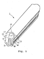
- FIG. 1 shows a hollow chamber profile 2 which has not yet been vulcanized shown from elastomeric material that is used to manufacture an inflatable Seal is provided.
- the profile has a mounting bead or web 20 for later anchoring of the profile on a portal pillar of a vehicle body, for example on the back of a stiffening area 22 of the profile.
- a shoulder-like Contact area 21 and on the other side of the mounting bead 22 on a wall area 23 On the to the mounting bead 20 opposite side, the stiffening region 22 an inclined wall 24, the material thickness from the area opposite the investment area 21 to the other end of the wall 24 opposite the wall area 23, 1 decreases from top to bottom in FIG.
- a flexible part extends from the area of the wall 24 Sealing wall 26 to form a slightly curved area 25 continues, which runs at a distance from the wall 24 and on the other side, thus opposite the curved area 25, has a fold 28.
- the sealing wall 26 On the opposite of the mounting bead 20 On the side, the sealing wall 26 has a plurality of extensions 30 on. Through the wall 24 and the flexible sealing wall 26 a chamber 32 is formed.
- Fig. 1 the seal is shown in the uninflated state. If the seal is inflated during use, the Chamber 32 formed by the sealing wall 26 expanded, wherein in particular the area of the fold 28 is expanded. On the one hand, this leads to a firm concern in the area the smaller gap width between door and portal in one Counter profile or the like takes place and on the other hand the Gasket inflated faster and stronger on the fold side becomes.
- FIG. 2 schematically illustrates the seal after vulcanization, i.e. with plug inserted on the front 4.
Landscapes
- Engineering & Computer Science (AREA)
- Mechanical Engineering (AREA)
- General Engineering & Computer Science (AREA)
- Physics & Mathematics (AREA)
- Architecture (AREA)
- Fluid Mechanics (AREA)
- Seal Device For Vehicle (AREA)
- Gasket Seals (AREA)
- Heating, Cooling, Or Curing Plastics Or The Like In General (AREA)
- Processing And Handling Of Plastics And Other Materials For Molding In General (AREA)
- Diaphragms And Bellows (AREA)
- Lining Or Joining Of Plastics Or The Like (AREA)
Abstract
Description
- Fig. 1
- eine perspektische Ansicht einer noch nicht verschlossenen aufblasbaren Dichtung und
- Fig. 2
- schematisch eine Stirnansicht der Dichtung von Fig. 1 nach der Vulkanisation.
Claims (9)
- Verfahren zur Herstellung einer aufblasbaren vulkanisierten Dichtung, bei dem ein oder mehrere Dichtungs- und/oder Verschlußteile (4) in eine Hohlkammer der Dichtung eingebracht werden und die Teile der Dichtung eine Vulkanisationsbehandlung erfahren,
dadurch gekennzeichnet, daß
ein Hohlkammerrohling (2) hergestellt wird,
in den Hohlkammerrohling (2) das (oder die) Dichtungsund/oder Verschlußteil(e) (4) eingebracht wird (werden),
womit der Dichtungsrohling erhalten wird und wobei die Teile des Dichtungsrohlings noch keine Vulkanisationsbehandlung erfahren haben, und
erst der so erhaltene Dichtungsrohling vulkanisiert wird. - Verfahren zur Herstellung eines aufblasbaren strangförmigen vulkanisierten Dichtungsprofils nach Anspruch 1, bei dem ein Hohlkammerprofilstrang extrudiert und die Enden des abgelängten Hohlkammerprofilstrangs mit Stopfen (4) verschlossen werden,
dadurch gekennzeichnet, daß
ein Hohlkammerprofilstrang extrudiert wird,
der Hohlkammerprofilstrang abgelängt wird und mit Stopfen als Formteil(e) (4) verschlossen wird und
der so erhaltene Dichtungsprofilrohling vulkanisiert wird. - Verfahren nach Anspruch 1 oder 2, dadurch gekennzeichnet, daß der Hohlkammerrohling mit den eingebrachten Dichtungs- und/oder Verschlußteilen in Formen verpreßt und der Dichtungsrohling erst anschließend vulkanisiert wird.
- Verfahren nach einem der Ansprüche 1 bis 3, dadurch gekennzeichnet, daß als Elastomermaterial EPDM (Ethylen-Propylen-Dien-Kautschuk) verwendet wird.
- Verfahren nach einem der Ansprüche 1 bis 4, dadurch gekennzeichnet, daß für die Hohlkammer und die Dichtungs- und/oder Verschlußteile dasselbe Elastomermaterial verwendet wird.
- Verfahren nach einem der Ansprüche 1 bis 5, dadurch gekennzeichnet, daß für die Dichtungs- und/oder Verschlußteile eine geringere Shore-Härte als für die Hohlkammer vorgesehen wird.
- Verfahren nach einem der Ansprüche 1 bis 6, dadurch gekennzeichnet, daß der Hohlkammerrohling vor der Vulkanisation innen mit flüssigen Seifen beschichtet wird.
- Verfahren nach einem der Ansprüche 1 bis 7, dadurch gekennzeichnet, daß die Dichtungs- und/oder Verschlußteile und/oder der Hohlkammerrohling vor der Vulkanisation mit Cyclohexanon und/ oder gummilöslichen Lösungsmitteln behandelt werden.
- Aufblasbare Dichtung, umfassend eine Dichtungshohlkammer und in diese eingebrachte Dichtungs- und/oder Verschlußteile, insbesondere Verschlußstopfen (4), insbesondere hergestellt unter Verwendung eines Verfahrens nach einem der Ansprüche 1 bis 8, dadurch gekennzeichnet, daß die Dichtüngshohlkammer (2) und die Dichtungs- und/oder Verschlußteile (4) zusammen durchvulkanisiert sind.
Applications Claiming Priority (2)
| Application Number | Priority Date | Filing Date | Title |
|---|---|---|---|
| DE10150827 | 2001-10-15 | ||
| DE10150827A DE10150827A1 (de) | 2001-10-15 | 2001-10-15 | Verfahren zur Herstellung einer aufblasbaren vulkanisierten Dichtung |
Publications (2)
| Publication Number | Publication Date |
|---|---|
| EP1302292A1 true EP1302292A1 (de) | 2003-04-16 |
| EP1302292B1 EP1302292B1 (de) | 2004-08-25 |
Family
ID=7702561
Family Applications (1)
| Application Number | Title | Priority Date | Filing Date |
|---|---|---|---|
| EP02022957A Expired - Lifetime EP1302292B1 (de) | 2001-10-15 | 2002-10-12 | Verfahren zur Herstellung einer aufblasbaren vulkanisierten Dichtung |
Country Status (6)
| Country | Link |
|---|---|
| EP (1) | EP1302292B1 (de) |
| AT (1) | ATE274408T1 (de) |
| DE (2) | DE10150827A1 (de) |
| DK (1) | DK1302292T3 (de) |
| ES (1) | ES2227374T3 (de) |
| PT (1) | PT1302292E (de) |
Cited By (2)
| Publication number | Priority date | Publication date | Assignee | Title |
|---|---|---|---|---|
| WO2005079137A2 (es) * | 2004-02-19 | 2005-09-01 | Grupo De Arquitectura Libre E Inxeñeria, S.L. | Sistema de junta mixta expansiva dinamica de epdm con resinas hidrofilicas moldeada y vulcanizada para sistemas de carpinteria |
| FR2915419A1 (fr) * | 2007-04-25 | 2008-10-31 | Polymeres Barre Thomas Societe | Procede et dispositif de traitement de section d'un profile en elastomere a armature metallique |
Families Citing this family (5)
| Publication number | Priority date | Publication date | Assignee | Title |
|---|---|---|---|---|
| DE102004019115B3 (de) * | 2004-04-20 | 2006-01-05 | Metzeler Automotive Profile Systems Gmbh | Verfahren zum Herstellen eines Dicht- oder Zierstreifens, insbesondere für ein Kraftfahrzeug, sowie ein solcher Dicht- oder Zierstreifen |
| DE102004019116B3 (de) * | 2004-04-20 | 2006-01-05 | Metzeler Automotive Profile Systems Gmbh | Verfahren zum Herstellen eines Dicht- oder Zierstreifens, insbesondere für ein Kraftfahrzeug, sowie ein solcher Dicht- oder Zierstreifen |
| DE102011075829B4 (de) | 2011-05-13 | 2013-07-11 | Metzeler Automotive Profiles Gmbh | Dichtung, insbesondere für ein Kraftfahrzeug, und Verfahren zur Herstellung einer solchen Dichtung |
| DE102014101752B4 (de) * | 2013-09-17 | 2023-09-21 | Cqlt Saargummi Technologies S.À.R.L. | Verfahren zur Bildung von Dichtungen an Dichtungsträgern |
| CN110539428B (zh) * | 2019-10-15 | 2022-08-30 | 陕西裕华永赫航宇科技有限公司 | 一种橡胶密封件的制备方法及其硫化模具 |
Citations (6)
| Publication number | Priority date | Publication date | Assignee | Title |
|---|---|---|---|---|
| DE2304171A1 (de) * | 1972-03-08 | 1973-09-13 | Semperit Gmbh | Verfahren zum stossverbinden von hohlprofilleisten aus elastischem material, insbesondere gummi |
| EP0055119A1 (de) * | 1980-12-19 | 1982-06-30 | J.M. Henshaw (Marine) Limited | Aufblasbare Abdichteinrichtungen |
| DE3735730A1 (de) * | 1987-10-22 | 1989-05-03 | Stricker Paul H Gummi | Verfahren zum verbinden von gummi-hohlprofilen |
| DE4230806C1 (de) * | 1992-09-15 | 1994-02-10 | Gummi Stricker Kautschuk Und K | Dichtungsring aus einem Gummi-Hohlkammerprofil und Verfahren zu seiner Herstellung |
| GB2273960A (en) * | 1993-01-04 | 1994-07-06 | Target Engineering | Inflatable tube for sealing or actuating |
| DE19645904A1 (de) * | 1996-11-07 | 1998-05-20 | Hausach Umformtechnik | Blähdichtring |
Family Cites Families (10)
| Publication number | Priority date | Publication date | Assignee | Title |
|---|---|---|---|---|
| US1966202A (en) * | 1932-07-26 | 1934-07-10 | S R Dresser Mfg Co | Liquid filled gasket |
| DE3730488A1 (de) * | 1987-09-11 | 1989-03-23 | Rehau Ag & Co | Verfahren zur herstellung eines blasformkoerpers |
| FR2664668B1 (fr) * | 1990-07-10 | 1994-01-14 | Joint Francais | Joint d'etancheite gonflable pour porte ou panneau coulissant. |
| DE4308214C2 (de) * | 1993-03-15 | 1996-12-12 | Metzeler Automotive Profiles | Dichtungsanordnung für einen Deckel an einem Fahrzeugdach |
| DE4402822C2 (de) * | 1994-01-31 | 1996-04-11 | Metzeler Automotive Profiles | Verfahren zur Herstellung von Stoßverbindungen bei aus EPDM bestehenden und mindestens eine Hohlkammer aufweisenden Gummiprofilen |
| DE19531184C2 (de) * | 1995-08-24 | 1997-09-11 | Metzeler Automotive Profiles | Elastomer-Verbundprofil sowie Verfahren und Vorrichtung zu dessen Herstellung |
| DE19630177A1 (de) * | 1996-07-26 | 1998-01-29 | Magna Zippex Autotechnik Gmbh | Randspaltabdichtungsprofil |
| DE19719474A1 (de) * | 1997-05-07 | 1998-10-08 | Bruegmann Frisoplast Gmbh | Strangdichtung |
| DE19924809C2 (de) * | 1999-05-29 | 2003-07-17 | Baedje K H Meteor Gummiwerke | Verfahren und Vorrichtung zur Konfektionierung einer Elastomerbaugruppe |
| DE19942037C1 (de) * | 1999-09-03 | 2001-02-01 | Webasto Dachsysteme Gmbh | Deckel eines öffnungsfähigen Fahrzeugdachs mit integrierter Dichtung |
-
2001
- 2001-10-15 DE DE10150827A patent/DE10150827A1/de not_active Ceased
-
2002
- 2002-10-12 DK DK02022957T patent/DK1302292T3/da active
- 2002-10-12 DE DE50200891T patent/DE50200891D1/de not_active Expired - Lifetime
- 2002-10-12 AT AT02022957T patent/ATE274408T1/de not_active IP Right Cessation
- 2002-10-12 ES ES02022957T patent/ES2227374T3/es not_active Expired - Lifetime
- 2002-10-12 PT PT02022957T patent/PT1302292E/pt unknown
- 2002-10-12 EP EP02022957A patent/EP1302292B1/de not_active Expired - Lifetime
Patent Citations (6)
| Publication number | Priority date | Publication date | Assignee | Title |
|---|---|---|---|---|
| DE2304171A1 (de) * | 1972-03-08 | 1973-09-13 | Semperit Gmbh | Verfahren zum stossverbinden von hohlprofilleisten aus elastischem material, insbesondere gummi |
| EP0055119A1 (de) * | 1980-12-19 | 1982-06-30 | J.M. Henshaw (Marine) Limited | Aufblasbare Abdichteinrichtungen |
| DE3735730A1 (de) * | 1987-10-22 | 1989-05-03 | Stricker Paul H Gummi | Verfahren zum verbinden von gummi-hohlprofilen |
| DE4230806C1 (de) * | 1992-09-15 | 1994-02-10 | Gummi Stricker Kautschuk Und K | Dichtungsring aus einem Gummi-Hohlkammerprofil und Verfahren zu seiner Herstellung |
| GB2273960A (en) * | 1993-01-04 | 1994-07-06 | Target Engineering | Inflatable tube for sealing or actuating |
| DE19645904A1 (de) * | 1996-11-07 | 1998-05-20 | Hausach Umformtechnik | Blähdichtring |
Cited By (3)
| Publication number | Priority date | Publication date | Assignee | Title |
|---|---|---|---|---|
| WO2005079137A2 (es) * | 2004-02-19 | 2005-09-01 | Grupo De Arquitectura Libre E Inxeñeria, S.L. | Sistema de junta mixta expansiva dinamica de epdm con resinas hidrofilicas moldeada y vulcanizada para sistemas de carpinteria |
| WO2005079137A3 (es) * | 2004-02-19 | 2005-12-29 | Grupo De Arquitectura Libre E | Sistema de junta mixta expansiva dinamica de epdm con resinas hidrofilicas moldeada y vulcanizada para sistemas de carpinteria |
| FR2915419A1 (fr) * | 2007-04-25 | 2008-10-31 | Polymeres Barre Thomas Societe | Procede et dispositif de traitement de section d'un profile en elastomere a armature metallique |
Also Published As
| Publication number | Publication date |
|---|---|
| EP1302292B1 (de) | 2004-08-25 |
| DE10150827A1 (de) | 2003-05-15 |
| ES2227374T3 (es) | 2005-04-01 |
| DK1302292T3 (da) | 2005-01-10 |
| PT1302292E (pt) | 2004-12-31 |
| ATE274408T1 (de) | 2004-09-15 |
| DE50200891D1 (de) | 2004-09-30 |
Similar Documents
| Publication | Publication Date | Title |
|---|---|---|
| EP0792216B1 (de) | Kraftfahrzeug-dichtungsprofil | |
| DE4037482C2 (de) | ||
| EP0076924B1 (de) | Verfahren zur Herstellung eines Dichtungs- und Halteprofils und Vorrichtung zur Durchführung des Verfahrens | |
| EP1084889B1 (de) | Tankeinsatz und Verfahren zu dessen Herstellung | |
| DE10058478A1 (de) | Flaches Filterelement mit angegossenem Rahmen | |
| DE10338195A1 (de) | Dichtlippe für ein Kraftfahrzeug und Verfahren zu dessen Herstellung | |
| DE102017105785A1 (de) | Türdichtungsstreifen für ein Fahrzeug | |
| DE69920889T2 (de) | Verfahren zum herstellen von dichtungsmaterial enthaltenden reifen, und dichtungsmaterial enthaltender reifen | |
| EP1302292B1 (de) | Verfahren zur Herstellung einer aufblasbaren vulkanisierten Dichtung | |
| DE60009828T2 (de) | Luftreifen und verfahren zur herstellung des luftreifens | |
| DE2063086A1 (de) | Verfahren zum Aufpumpen von Reifen mit einem schaumbaren Produkt | |
| DE4301026A1 (de) | Für die Verklebung mit einem Fensterrahmen vorgerüstete Autoglasscheibe und Verfahren zu ihrer Herstellung | |
| EP1946951B1 (de) | Verfahren zur Herstellung einer Dichtung, insbesondere für ein Kraftfahrzeug, und eine solche Dichtung | |
| DE3300509A1 (de) | Dichtungsprofil aus elastomerem material, insbesondere fuer kraftfahrzeugkarosserien, und verfahren zu dessen herstellung | |
| DE60106079T2 (de) | Aus einem luftreifen und einem dichtungsteil bestehende einheit und herstellungsverfahren | |
| DE19504828C2 (de) | Verfahren zum Herstellen und Verbinden eines Rahmens mit einer Glasscheibe und Vorrichtung zum Durchführen des Verfahrens | |
| DE102005024527A1 (de) | Vorrichtung zur Zwangsentlüftung eines Innenraums eines Kraftfahrzeugs und Verfahren zu deren Herstellung | |
| DE102005012685A1 (de) | Verfahren zum Herstellen eines Dichtungsstranges, insbesondere für ein Kraftfahrzeug, und ein solcher Dichtungsstrang | |
| EP3464726A1 (de) | Schwellenbesohlung | |
| DE3930528C2 (de) | ||
| EP0760275A2 (de) | Heizbalg aus Gummi für die Vulkanisation von Reifen oder Luftfedern | |
| DE4209687A1 (de) | Reifen für ein Fahrzeug, insbesondere für ein Kraftfahrzeug sowie Verfahren zu dessen Herstellung | |
| DE2900717A1 (de) | Verfahren und vorrichtung zum formen und vulkanisieren von reifen ohne entlueftungsvorspruenge | |
| DE1143632B (de) | Verfahren und Stift zur Bildung einer Ventilaufnahmeoeffnung in der Seiten-wand eines Fahrzeugluftreifens | |
| WO2001035007A1 (de) | Dichtrahmen |
Legal Events
| Date | Code | Title | Description |
|---|---|---|---|
| PUAI | Public reference made under article 153(3) epc to a published international application that has entered the european phase |
Free format text: ORIGINAL CODE: 0009012 |
|
| AK | Designated contracting states |
Designated state(s): AT BE BG CH CY CZ DE DK EE ES FI FR GB GR IE IT LI LU MC NL PT SE SK TR |
|
| AX | Request for extension of the european patent |
Extension state: AL LT LV MK RO SI |
|
| 17P | Request for examination filed |
Effective date: 20031010 |
|
| AKX | Designation fees paid |
Designated state(s): AT BE BG CH CY CZ DE DK EE ES FI FR GB GR IE IT LI LU MC NL PT SE SK TR |
|
| GRAP | Despatch of communication of intention to grant a patent |
Free format text: ORIGINAL CODE: EPIDOSNIGR1 |
|
| GRAS | Grant fee paid |
Free format text: ORIGINAL CODE: EPIDOSNIGR3 |
|
| GRAA | (expected) grant |
Free format text: ORIGINAL CODE: 0009210 |
|
| AK | Designated contracting states |
Kind code of ref document: B1 Designated state(s): AT BE BG CH CY CZ DE DK EE ES FI FR GB GR IE IT LI LU MC NL PT SE SK TR |
|
| PG25 | Lapsed in a contracting state [announced via postgrant information from national office to epo] |
Ref country code: SK Free format text: LAPSE BECAUSE OF FAILURE TO SUBMIT A TRANSLATION OF THE DESCRIPTION OR TO PAY THE FEE WITHIN THE PRESCRIBED TIME-LIMIT Effective date: 20040825 Ref country code: EE Free format text: LAPSE BECAUSE OF FAILURE TO SUBMIT A TRANSLATION OF THE DESCRIPTION OR TO PAY THE FEE WITHIN THE PRESCRIBED TIME-LIMIT Effective date: 20040825 Ref country code: BG Free format text: LAPSE BECAUSE OF FAILURE TO SUBMIT A TRANSLATION OF THE DESCRIPTION OR TO PAY THE FEE WITHIN THE PRESCRIBED TIME-LIMIT Effective date: 20040825 |
|
| REG | Reference to a national code |
Ref country code: GB Ref legal event code: FG4D Free format text: NOT ENGLISH |
|
| REG | Reference to a national code |
Ref country code: CH Ref legal event code: EP |
|
| REG | Reference to a national code |
Ref country code: IE Ref legal event code: FG4D Free format text: GERMAN |
|
| REF | Corresponds to: |
Ref document number: 50200891 Country of ref document: DE Date of ref document: 20040930 Kind code of ref document: P |
|
| REG | Reference to a national code |
Ref country code: CH Ref legal event code: NV Representative=s name: DR. JOACHIM LAUER PATENTANWALT |
|
| PG25 | Lapsed in a contracting state [announced via postgrant information from national office to epo] |
Ref country code: MC Free format text: LAPSE BECAUSE OF NON-PAYMENT OF DUE FEES Effective date: 20041031 |
|
| REG | Reference to a national code |
Ref country code: SE Ref legal event code: TRGR |
|
| GBT | Gb: translation of ep patent filed (gb section 77(6)(a)/1977) |
Effective date: 20041126 |
|
| REG | Reference to a national code |
Ref country code: PT Ref legal event code: SC4A Free format text: AVAILABILITY OF NATIONAL TRANSLATION Effective date: 20041105 |
|
| REG | Reference to a national code |
Ref country code: GR Ref legal event code: EP Ref document number: 20040404064 Country of ref document: GR |
|
| LTIE | Lt: invalidation of european patent or patent extension |
Effective date: 20040825 |
|
| REG | Reference to a national code |
Ref country code: ES Ref legal event code: FG2A Ref document number: 2227374 Country of ref document: ES Kind code of ref document: T3 |
|
| PLBE | No opposition filed within time limit |
Free format text: ORIGINAL CODE: 0009261 |
|
| STAA | Information on the status of an ep patent application or granted ep patent |
Free format text: STATUS: NO OPPOSITION FILED WITHIN TIME LIMIT |
|
| ET | Fr: translation filed | ||
| 26N | No opposition filed |
Effective date: 20050526 |
|
| PGFP | Annual fee paid to national office [announced via postgrant information from national office to epo] |
Ref country code: TR Payment date: 20090930 Year of fee payment: 8 |
|
| PGFP | Annual fee paid to national office [announced via postgrant information from national office to epo] |
Ref country code: AT Payment date: 20091022 Year of fee payment: 8 Ref country code: CH Payment date: 20091026 Year of fee payment: 8 Ref country code: CZ Payment date: 20090930 Year of fee payment: 8 Ref country code: DK Payment date: 20091023 Year of fee payment: 8 Ref country code: ES Payment date: 20091026 Year of fee payment: 8 Ref country code: FI Payment date: 20091026 Year of fee payment: 8 Ref country code: IE Payment date: 20091021 Year of fee payment: 8 Ref country code: LU Payment date: 20091026 Year of fee payment: 8 Ref country code: SE Payment date: 20091023 Year of fee payment: 8 |
|
| PGFP | Annual fee paid to national office [announced via postgrant information from national office to epo] |
Ref country code: NL Payment date: 20091027 Year of fee payment: 8 Ref country code: SK Payment date: 20091008 Year of fee payment: 8 |
|
| PGFP | Annual fee paid to national office [announced via postgrant information from national office to epo] |
Ref country code: CY Payment date: 20091007 Year of fee payment: 8 Ref country code: PT Payment date: 20090929 Year of fee payment: 8 |
|
| PGFP | Annual fee paid to national office [announced via postgrant information from national office to epo] |
Ref country code: FR Payment date: 20091110 Year of fee payment: 8 Ref country code: GB Payment date: 20091023 Year of fee payment: 8 Ref country code: IT Payment date: 20091024 Year of fee payment: 8 |
|
| PGFP | Annual fee paid to national office [announced via postgrant information from national office to epo] |
Ref country code: BE Payment date: 20091029 Year of fee payment: 8 |
|
| PGFP | Annual fee paid to national office [announced via postgrant information from national office to epo] |
Ref country code: DE Payment date: 20091214 Year of fee payment: 8 Ref country code: GR Payment date: 20091022 Year of fee payment: 8 |
|
| REG | Reference to a national code |
Ref country code: PT Ref legal event code: MM4A Free format text: LAPSE DUE TO NON-PAYMENT OF FEES Effective date: 20110412 |
|
| BERE | Be: lapsed |
Owner name: *GUMMI-WELZ G.M.B.H. & CO. K.G. Effective date: 20101031 |
|
| REG | Reference to a national code |
Ref country code: NL Ref legal event code: V1 Effective date: 20110501 |
|
| REG | Reference to a national code |
Ref country code: DK Ref legal event code: EBP |
|
| REG | Reference to a national code |
Ref country code: CH Ref legal event code: PL |
|
| GBPC | Gb: european patent ceased through non-payment of renewal fee |
Effective date: 20101012 |
|
| REG | Reference to a national code |
Ref country code: SK Ref legal event code: MM4A Ref document number: E 88 Country of ref document: SK Effective date: 20101012 |
|
| PG25 | Lapsed in a contracting state [announced via postgrant information from national office to epo] |
Ref country code: PT Free format text: LAPSE BECAUSE OF NON-PAYMENT OF DUE FEES Effective date: 20110412 Ref country code: CH Free format text: LAPSE BECAUSE OF NON-PAYMENT OF DUE FEES Effective date: 20101031 Ref country code: GR Free format text: LAPSE BECAUSE OF NON-PAYMENT OF DUE FEES Effective date: 20110503 Ref country code: FR Free format text: LAPSE BECAUSE OF NON-PAYMENT OF DUE FEES Effective date: 20101102 Ref country code: LI Free format text: LAPSE BECAUSE OF NON-PAYMENT OF DUE FEES Effective date: 20101031 Ref country code: CZ Free format text: LAPSE BECAUSE OF NON-PAYMENT OF DUE FEES Effective date: 20101012 |
|
| REG | Reference to a national code |
Ref country code: FR Ref legal event code: ST Effective date: 20110630 |
|
| REG | Reference to a national code |
Ref country code: IE Ref legal event code: MM4A |
|
| PG25 | Lapsed in a contracting state [announced via postgrant information from national office to epo] |
Ref country code: CY Free format text: LAPSE BECAUSE OF NON-PAYMENT OF DUE FEES Effective date: 20101012 Ref country code: FI Free format text: LAPSE BECAUSE OF NON-PAYMENT OF DUE FEES Effective date: 20101012 Ref country code: SK Free format text: LAPSE BECAUSE OF NON-PAYMENT OF DUE FEES Effective date: 20101012 Ref country code: AT Free format text: LAPSE BECAUSE OF NON-PAYMENT OF DUE FEES Effective date: 20101012 Ref country code: GB Free format text: LAPSE BECAUSE OF NON-PAYMENT OF DUE FEES Effective date: 20101012 Ref country code: NL Free format text: LAPSE BECAUSE OF NON-PAYMENT OF DUE FEES Effective date: 20110501 Ref country code: BE Free format text: LAPSE BECAUSE OF NON-PAYMENT OF DUE FEES Effective date: 20101031 |
|
| REG | Reference to a national code |
Ref country code: DE Ref legal event code: R119 Ref document number: 50200891 Country of ref document: DE Effective date: 20110502 |
|
| PG25 | Lapsed in a contracting state [announced via postgrant information from national office to epo] |
Ref country code: SE Free format text: LAPSE BECAUSE OF NON-PAYMENT OF DUE FEES Effective date: 20101013 |
|
| PG25 | Lapsed in a contracting state [announced via postgrant information from national office to epo] |
Ref country code: DK Free format text: LAPSE BECAUSE OF NON-PAYMENT OF DUE FEES Effective date: 20101031 Ref country code: IE Free format text: LAPSE BECAUSE OF NON-PAYMENT OF DUE FEES Effective date: 20101012 |
|
| REG | Reference to a national code |
Ref country code: ES Ref legal event code: FD2A Effective date: 20111118 |
|
| PG25 | Lapsed in a contracting state [announced via postgrant information from national office to epo] |
Ref country code: IT Free format text: LAPSE BECAUSE OF NON-PAYMENT OF DUE FEES Effective date: 20101012 |
|
| PG25 | Lapsed in a contracting state [announced via postgrant information from national office to epo] |
Ref country code: ES Free format text: LAPSE BECAUSE OF NON-PAYMENT OF DUE FEES Effective date: 20101013 |
|
| PG25 | Lapsed in a contracting state [announced via postgrant information from national office to epo] |
Ref country code: LU Free format text: LAPSE BECAUSE OF NON-PAYMENT OF DUE FEES Effective date: 20101012 |
|
| PG25 | Lapsed in a contracting state [announced via postgrant information from national office to epo] |
Ref country code: TR Free format text: LAPSE BECAUSE OF NON-PAYMENT OF DUE FEES Effective date: 20101012 |
|
| PG25 | Lapsed in a contracting state [announced via postgrant information from national office to epo] |
Ref country code: DE Free format text: LAPSE BECAUSE OF NON-PAYMENT OF DUE FEES Effective date: 20110502 |