EP1295702B1 - Reifenaufbautrommel mit einem Mittelteil und Endteilen, die unabhängig voneinander ausdehnbar sind - Google Patents
Reifenaufbautrommel mit einem Mittelteil und Endteilen, die unabhängig voneinander ausdehnbar sind Download PDFInfo
- Publication number
- EP1295702B1 EP1295702B1 EP02021255A EP02021255A EP1295702B1 EP 1295702 B1 EP1295702 B1 EP 1295702B1 EP 02021255 A EP02021255 A EP 02021255A EP 02021255 A EP02021255 A EP 02021255A EP 1295702 B1 EP1295702 B1 EP 1295702B1
- Authority
- EP
- European Patent Office
- Prior art keywords
- drum
- tire
- segments
- center section
- piston
- Prior art date
- Legal status (The legal status is an assumption and is not a legal conclusion. Google has not performed a legal analysis and makes no representation as to the accuracy of the status listed.)
- Expired - Fee Related
Links
Images


Classifications
-
- B—PERFORMING OPERATIONS; TRANSPORTING
- B29—WORKING OF PLASTICS; WORKING OF SUBSTANCES IN A PLASTIC STATE IN GENERAL
- B29D—PRODUCING PARTICULAR ARTICLES FROM PLASTICS OR FROM SUBSTANCES IN A PLASTIC STATE
- B29D30/00—Producing pneumatic or solid tyres or parts thereof
- B29D30/06—Pneumatic tyres or parts thereof (e.g. produced by casting, moulding, compression moulding, injection moulding, centrifugal casting)
- B29D30/08—Building tyres
- B29D30/20—Building tyres by the flat-tyre method, i.e. building on cylindrical drums
- B29D30/24—Drums
- B29D30/244—Drums for manufacturing substantially cylindrical tyre components with cores or beads, e.g. carcasses
- B29D30/246—Drums for the multiple stage building process, i.e. the building-up of the cylindrical carcass is realised on one drum and the toroidal expansion is realised after transferring on another drum
- B29D30/247—Arrangements for the first stage only, e.g. means for radially expanding the drum to lock the beads
-
- B—PERFORMING OPERATIONS; TRANSPORTING
- B29—WORKING OF PLASTICS; WORKING OF SUBSTANCES IN A PLASTIC STATE IN GENERAL
- B29D—PRODUCING PARTICULAR ARTICLES FROM PLASTICS OR FROM SUBSTANCES IN A PLASTIC STATE
- B29D30/00—Producing pneumatic or solid tyres or parts thereof
- B29D30/06—Pneumatic tyres or parts thereof (e.g. produced by casting, moulding, compression moulding, injection moulding, centrifugal casting)
- B29D30/08—Building tyres
- B29D30/20—Building tyres by the flat-tyre method, i.e. building on cylindrical drums
- B29D30/32—Fitting the bead-rings or bead-cores; Folding the textile layers around the rings or cores
- B29D2030/3214—Locking the beads on the drum; details of the drum in the bead locking areas, e.g. drum shoulders
Definitions
- the present invention relates to tire building drums for laying up tire carcasses, more particularly to drums which are expandable between a collapsed position and an expanded position.
- the invention also relates to methods and apparatus for setting beads on green tire carcasses.
- the main components can be considered to include a so-called inner liner that is a layer of elastomeric air-impervious material, a carcass ply, a pair of annular metal elements, commonly referred to as bead cores, around which the opposite ends of the carcass ply are folded, as well as a pair of sidewalls made of elastomeric material, extending over the carcass ply at laterally opposite positions.
- the accessory components may in turn comprise of one or more additional carcass plies, one or more reinforcing bands for overlying the carcass ply or plies at the areas turned up around the bead cores (chafer strips), and others.
- a tread which "snakes" as it goes around the tire circumference will cause wobbling as the tire is operated.
- a carcass ply which is lopsided longer cords on one side of the tire than the other side
- tire nonuniformity problems including static imbalance and radial force variations.
- a tire which is not meridionally symmetric e.g., tread not centered between beads
- tire nonuniformity problems including couple imbalance, lateral force variations, and conicity.
- Tire uniformity is generally considered to mean tire dimensions and mass distributions which are uniform and symmetric radially, laterally, circumferentially, and meridionally, thereby producing acceptable results for measurements of tire uniformity including static and dynamic balance, and also including radial force variation, lateral force variation, and tangential force variation as measured on tire uniformity machines which run the tire under load on a road wheel.
- Typical tire building machines comprise a tire building drum around which the tire components are wrapped in successive layers including, for example, an innerliner, one or more carcass plies, optional sidewall stiffeners and bead area inserts (e.g., apex), sidewalls and bead wire rings (beads). After this layering, the carcass ply ends are wrapped around the beads, the tires are blown up into a toroidal shape, and the tread/belt package is applied.
- an innerliner one or more carcass plies
- sidewall stiffeners and bead area inserts e.g., apex
- sidewalls and bead wire rings bead wire rings
- the tire builder must stitch the interfaces between the uncured elastomeric components to work any bubbles or trapped air from between the components.
- This stitching involves rolling a roller wheel along the components, forcing the air to an edge of a component where it can escape.
- the stitching process is time consuming and requires the skill of the tire builder.
- this problem is further magnified in tire designs where components are rather thick compared to other components. For example, when a component having a relatively square cross-section, such as a tire bead, is positioned adjacent a more planar component, such as a ply, the air may be trapped where the different-shaped components interface.
- inserts are positioned in the sidewall between the carcass plies to enable the tire to support the weight of the vehicle even if the tire should lose inflation pressure. These inserts are typically thicker than the plies which lie adjacent to them and it is important that this tire be built without trapping air between the plies and inserts.
- an inventive tire building method and drum have been designed which have features to accommodate the special production needs of such tires. These special features will be described hereinafter and contribute to the building of a quality tire without trapping air.
- Becker therefore provides a method of building a tire comprising the steps of forming a liner into a cylinder, positioning first inserts to indent the liner cylindrical surface circumferentially at axially spaced insert locations along the axis of the cylinder, laying a first ply of reinforcing material around the cylindrical surface of the liner and first insert, positioning second inserts over the first ply at the spaced insert locations, laying a second ply of reinforcing material over the first ply and the second inserts, positioning circular beads at each end of the cylinder, expanding the first ply and the second ply to increase the diameter of the cylinder between the circular beads to provide shoulders at each end of the cylinder, turning edges of the first ply around the second ply over each of the beads, and positioning a belt and tread assembly around the second ply to form a precured tire.
- Becker further provides a method of assembling tire components on a tire building drum having a cylindrical surface comprising the steps of laying a liner on the surface of the drum, positioning first inserts below the cylindrical surface and around a drum at insert locations spaced from each end of the drum, laying a first ply of reinforcing material around the drum over the cylindrical surface of the liner and first insert, positioning second inserts over the first ply at the insert locations spaced from each end of the drum, laying a second ply of reinforcing material over the first ply and the second inserts, positioning circular beads at each end of the drum, expanding the drum to increase the diameter of the cylindrical surface and provide shoulders at each end of the drum, turning edges of the first ply and the second ply over each of the beads, positioning a belt and tread assembly around the second ply, and contracting the drum for removal of the assembled tire components from the drum.
- Becker further provides a tire building drum which has a cylindrical surface, circular grooves in the surface at insert locations spaced from each end of the drum for positioning of first inserts below the surface, means for applying a first ply over the cylindrical surface, means for applying second inserts over the first ply and the first inserts, means for applying a second ply over the first ply and second insert, means for expanding the drum providing shoulders at each end of the drum for applying bead rings, means for turning up ends of the first ply around the beads, means for applying a belt and tread assembly around the second ply and means for contracting the drum to remove the assembled tire from the drum.
- the tire reinforcing plies, beads and other components are assembled on the first stage drum and then the carcass is moved to another location where it is shaped and the belt and tread applied.
- the tire components be applied to contracted and expanded drum surfaces which are concentric and of uniform diameter along the length of the drum.
- Expandible drums of different constructions have been used heretofore; however it has been difficult to maintain a concentric drum surface and a uniform diameter along the length of the drum in both the expanded and contracted condition of the drum.
- the drum surface may be concentric and uniform in the contracted condition but is distorted during expansion to a larger diameter.
- the components added to the carcass on the expanded drum are not precisely assembled which may adversely affect the uniformity of the tire.
- US-A- 5,264,068 discloses an expandable drum including adjustable stops for setting drum circumference.
- Tapering structures each having axial slidability, are provided, and in response to a slide move of the tapering structure, drum segments are each radially expanded or retracted.
- the tapering structure (12) is of an inner recessed frustum and is mounted over the drum shaft (10) longitudinally or axially slidable with the aid of a key (16), and housed in the drum (14).
- the drum (14) is circumferentially divided into a plurality of drum segments (17), each being like a sector, and each segment (17) is interiorly supported by a drum segment supporter (18).
- a tire building drum including an expandable segmental cylinder assembly and a vacuum Chamber.
- the drum (10) has a plurality of axially-extending, circumferentially spaced segments (18). The ends of the drum are sealed to provide a vacuum chamber (76) inside the drum which is in communication with vacuum holes (78) in a cover sleeve (48) to hold tire components on the drum surface (58) during assembly of the tire components.
- DE-B- 12 40 267 discloses a segmented drum for building pneumatic tires having two groups of segments that are independently, radially movable. Further reference is made to EP0970802 A2.
- a tire building drum has a center section and two end sections. Each end section is provided with an expandable bead lock assembly.
- the center section is preferably expandable.
- the expandable bead lock assembly comprises a carrier ring and a plurality of elongate links extending between the carrier ring and a plurality of radially-expandable segments. When the carrier ring moves inward (towards the center section), the radially-expandable segments move radially outward, urging a plurality of axially extending, circumferentially spaced-apart finger segments outward from a collapsed position to an expanded position, and at least one position therebetween.
- the bead lock assembly comprises a cylinder and two pistons disposed within the cylinder.
- the pistons are free to move axially within the cylinder, in response to pneumatic pressure.
- the first piston is constrained from moving axially inward by rods.
- the second piston is connected by rods to the carrier ring. Pressurized air supplied through air lines and passageways in the cylinder control the movement of the pistons so that the beach lock assembly can be partially-expanded, fully-expanded, and retracted.
- the bead lock assembly of the present invention works well in combination with a tire building drum having an expandable center section.
- a tire building drum has alternating fixed and expanding segments in a center section of the drum.
- the expanding segments are axially-extending and circumferentially spaced-apart from one another, and their end portions are contoured (have recesses, or grooves) to accommodate tire components such as sidewall inserts.
- Two different mechanisms for expanding the center section are described.
- a first mechanism includes two wedge elements which are axially moveable away from one another to expand the center section. Ramp elements associated with the expanding segments may thus be moved radially outward. Biasing elements provide a restoring force for collapsing the center section.
- a second mechanism includes two guide rings which are axially moveable towards one another for expanding the center section, and away from one another to collapse the center section. Overlapping links are provided between the guide rings and a base member supporting the expanding segments.
- Elements of the figures are typically numbered as follows. The most significant digit (hundreds) of the reference number corresponds to the figure number. Elements of Figure 1 are typically numbered in the range of 100-199. Elements of Figure 2 are typically numbered in the range of 200-299. Similar elements throughout the drawings may be referred to by similar reference numerals.
- the element 199 in a figure may be similar, and possibly identical to the element 299 in another figure. Elements of the figures can be numbered such that similar (including identical) elements may be referred to with similar numbers in a single drawing.
- each of a plurality of elements collectively referred to as 199 may be referred to individually as 199a, 199b, 199c, etc.
- 109, 109', and 109" are three different elements which are similar or related in some way, but have significant modifications. Such relationships, if any, between similar elements in the same or different figures will become apparent throughout the specification, including, if applicable, in the claims and abstract.
- similar elements are referred to with the suffixes -L and -R (e.g., 133L, 133R), which generally indicate left and right, as viewed in the drawing.
- Adex (also “Bead Apex”) refers to an elastomeric filler located radially above the bead core and between the plies and the turnup plies.
- Axial and “axially” refers to directions that are on or are parallel to the tire's axis of rotation.
- Bead refers to that part of the tire comprising an annular substantially inextensible tensile member, typically comprising a cable of steel filaments encased in rubber material.
- Belt structure or “reinforcement belts” or “belt package” refers to at least two annular layers or plies of parallel cords, woven or unwoven, underlying the tread, unanchored to the bead, and having both left and right cord angles in the range from 18 to 30 degrees relative to the equatorial plane of the tire.
- “Breakers” or “tire breakers” refers to a belt or belt structure or reinforcement belts.
- Carcass refers to the tire structure apart from the belt structure, tread, undertread over the plies and the sidewalls, but including the beads, plies, and, in the case of EMT or runflat tires, the wedge inserts sidewall reinforcements.
- Crosing refers to the carcass, belt structure, beads, sidewalls and all other components of the tire excepting the tread and undertread.
- Centerplane refers to a plane intersecting a line which is normal to the plane at a point which is midway between two other points on the line.
- the line may be an axis of a cylindrical member, such as a tire building drum.
- a finished tire has a centerplane which is the "equatorial plane" of the tire.
- “Chafer” refers to reinforcing material (rubber alone, or fabric and rubber) around the bead in the rim flange area to prevent chafing of the tire by the rim parts.
- Chipper refers to a narrow band of fabric or steel cords located in the bead area whose function is to reinforce the bead area and stabilize the radially inwardmost part of the sidewall.
- “Circumferential” refers to circular lines or directions extending along the perimeter of the surface of the annular tread perpendicular to the axial direction, and can also refer to the direction of sets of adjacent circular curves whose radii define the axial curvature of the tread, as viewed in cross section.
- Core refers to one of the reinforcement strands, including fibers or metal or fabric, with which the plies and belts are reinforced.
- “Crown” or “tire crown” refers to the tread, tread shoulders and the immediately adjacent portions of the sidewalls.
- EMT tire refers to Extended Mobility Technology and EMT tire refers to a tire which is a “runflat”, which refers to a tire that is designed provide at least limited operational service under conditions when the tire has little to no inflation pressure.
- Equatorial plane refers to a the plane perpendicular to the tire's axis of rotation and passing through the center of its tread, or midway between the tire's beads.
- “Gauge” refers generally to a measurement, and often to a thickness dimension.
- Inner liner refers to the layer or layers of elastomer or other material that form the inside surface of a tubeless tire and that contain the inflating gas or fluid within the tire.
- Halobutyl which is highly impermeable to air.
- Insert refers to the crescent-shaped or wedge-shaped reinforcement typically used to reinforce the sidewalls of runflat-type tires; it also refers to the elastomeric non-crescent-shaped insert that underlies the tread; it is also called a "wedge insert.”
- “Lateral” refers to a direction parallel to the axial direction.
- Tire profile refers to a tire profile cut along a plane that includes the tire axis.
- Ply refers to a cord-reinforced carcass reinforcing member (layer) of rubber-coated radially deployed or otherwise parallel cords.
- Pneumatic tire refers to a laminated mechanical device of generally toroidal shape (usually an open-torus) having two beads, two sidewalls and a tread and made of rubber, chemicals, fabric and steel or other materials.
- Shader refers to the upper portion of sidewall just below the tread edge.
- “Sidewall” refers to that portion of a tire between the tread and the bead.
- Tire axis refers to the tire's axis of rotation when the tire is mounted to a wheel rim and is rotating.
- Thread cap refers to the tread and the underlying material into which the tread pattern is molded.
- “Turn-up end” refers to a portion of a carcass ply that turns upward (i.e., radially outward) from the beads about which the ply is wrapped.
- a conventional process for making a radial-ply automobile tire includes an intermediate step of disposing two annular inextensible beads, each comprising a cable of steel filaments encased in green rubber, over the other components of a green ("green" meaning as yet uncured and still tacky) tire carcass on a tire building drum.
- An annular cross-sectionally triangular rubber filler called an "apex" may be added. Portions of the ply components that extend beyond the beads are then turned up around the beads, forming "turn-ups".
- the green carcass is typically removed from the tire building drum and mounted on a "second stage machine" where it is inflated (reshaped) to a toroidal shape, and its radially-outer surface is pressed against a tread and belt package.
- the green carcass is stitched (rolled with a roller) to remove air pockets and adhere internal surfaces together.
- the resulting assembly is inserted into a mold (vulcanizing press) to cure under heat (typically 350 degrees Fahrenheit) and pressure to become a finished tire.
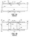
- FIG. 1A corresponds generally to FIG. 9 of the above mentioned Becker patent, and illustrates (schematically, and in a greatly simplified manner) an exemplary tire building drum 102 of the prior art.
- the drum 102 is generally cylindrical, having two ends 102a and 102b, an axis of rotation 104 extending between the two ends, and a cylindrical outer surface 106.
- a centerplane (CP) is indicated on the drawing, and is generally a plane which bisects a carcass being laid up on the tire building drum.
- an inner liner 108 is applied on the surface of the drum 102, and two tire sidewall insert components (“inserts”) 110a and 110b (collectively referred to as "110") are disposed at longitudinally (axially) spaced apart positions on the inner liner 108, as shown.
- a first ply 112 is disposed over the inner liner 108 and inserts 110. This results in a green tire carcass having a nominally cylindrical shape.
- each bead 114 is a substantially inextensible circular hoop, having an inside diameter ("ID") which is substantially equal to or preferably only slightly greater than the OD of the ply 112 (in areas other than where there are bumps).
- ID inside diameter
- the beads 114 are shown as being slightly axially outboard of the inserts 110, and are shown as having a round (versus hexagonal) cross-section for sake of illustrative clarity.
- a second ply (not shown) may be added to the carcass, and the outer end portions of the carcass may be turned up. Finally the carcass may be transferred to another (second stage) machine for adding a tread package, etc.
- FIG 1B corresponds generally to FIGs. 2-7 of above mentioned “Becker” patent, and illustrates an alternate embodiment of an exemplary tire building drum 122 of the prior art.
- the drum 122 is generally cylindrical, having two ends 122a and 122b, an axis of rotation 124, and a generally cylindrical outer surface 126.
- the drum 122 differs from the drum 102 of Figure 1A primarily by virtue of having annular recesses (pockets, grooves) 136a and 136b (collectively referred to as "136") in its outer surface at longitudinal (axial) positions corresponding to the positions of and related to the dimensions of inserts 130a and 130b (collectively referred to as "130”) and extending about the circumference of the drum 122.
- annular recesses pockets, grooves
- the inner liner 128 is applied to the surface 126 of the drum 122. Then the inserts 130 are applied, and fit (nestle) down into the recesses 136. Then a ply 132 is applied. This results in a green tire carcass having a substantially cylindrical shape. In contrast to the tire carcass formed in Figure 1A, the addition of the inserts 130 between the inner liner 128 and the ply 132 does not cause there to be two "bumps" in the outer surface of the carcass.
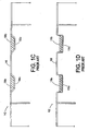
- FIGS 2A through 2D illustrate, generally, the tire building drum 202 of the present invention.
- the drum 202 is generally cylindrical, having two ends 202a and 202b, an axis of rotation 204 extending between the two ends, and a cylindrical outer surface 206.
- the drum 202 has an overall axial length "L" between the two ends.
- a spindle (or drum support shaft) extends along the axis 204 and has an end 208a extending from the end 202a of the drum 202, and an end 208b extending from the end 202b of the drum 202.
- the drum 202 has a center section 220 which is generally cylindrical, and centered about the axis 204.
- the center section 220 has a width (more properly, axial length) of "L c ".
- the drum 202 has a first end section 222 which is coaxial with the center section 220, and which is disposed axially at one end of the center section 220.
- the drum 202 has a second end section 224 which is coaxial with the center section 220, and which is disposed axially at an opposite end of the center section 220.
- the two end sections 222 and 224 are, for purposes of the present invention, substantially identical to (i.e., mirror images of) one another, each having an axial length of (L- L c )/2.
- the end sections 222 and 224 are axially-outward of the center section 220.
- the drum more significantly the center section 220 of the drum, has a centerplane (compare CP, Figure 1A), which is a plane intersecting the axis 204 midway between the ends of the center section (typically also midway between the ends 202a, 202b) of the overall drum.
- the axis 204 is, by definition, normal to the centerplane.
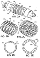
- the center section 220 is circumferentially segmented, having a plurality of elongate fixed segments 226 alternating with a like plurality of elongate expanding segments 228. As best viewed in any of Figures 2B-2D, there are suitably 24 (twenty four) fixed segments 226 alternating with 24 (twenty four) expanding segments 228.
- the expanding segments 228 are axially-extending and circumferentially spaced from one another, and end portions of each is contoured to have annular recesses (pockets, grooves) 236a and 236b (collectively referred to as "236"; compare 136) in its outer surface at longitudinal (axial) positions corresponding to the positions of and related to the dimensions of sidewall inserts (not shown, compare 130) which will be applied during the carcass layup process, described hereinabove.
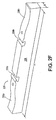
- the pockets 236 can best be viewed in Figure 2F, wherein can also be viewed two turnup bladder (not shown) anchor points 238a and 238b in the outer surface of the expanding segment.
- end portions of the expanding segments 238, 538 are contoured to have pockets 236, 536 for receiving components (e.g., sidewall inserts) of a tire carcass being laid up on the drum.
- the fixed segments 226 are elongate, generally rectangular in cross-section and have a length substantially equal to "L c ".
- the fixed segments 226 typically have a fixed width or have a width proportional to the number of total segments.
- the expanding segments 228 are also elongate, generally rectangular in cross section, a length substantially equal to "L c "., and typically have a fixed width or have a width proportional to the number of total segments.
- the expanding segments 228 are also elongate, generally rectangular in cross section, and have a length substantially equal to "L c ".
- the number of fixed and expanding segments may be not exactly equal to the number of expanding segments.
- the expanding segments may also not all have the exact same width. The same applies to the fixed segments. Selected ones of the fixed and/or expanding segments can be "special purpose" segments, such as for communicating vacuum to an inner liner being laid up on the drum.
- the center section 220 is expandable, between a collapsed (or retracted, or contracted) condition, shown in Figures 2B and 2C and an expanded (or extended) condition (or “fully” expanded position), shown in Figures 2D and 2E.
- Mechanisms for effecting expansion and collapse of the center section 220 are described hereinbelow, and accommodate partially expanding the center section to one (or more) "semi-expanded" positions.
- each of said expanding segments 228 is expandable from a first drum radius in the a collapsed condition of the drum to a second, greater drum radius in a semi-expanded condition of the drum and finally drum to a third drum radius, greater than the second radius in a fully expanded condition of the drum.
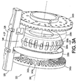
- Figures 3A-3D illustrate the major components of an expandable center section 320 (compare 220) of a tire building drum, according to an embodiment of the invention.
- one of a plurality (e.g., 24) of expanding segments 328 (compare 228) is shown, and a corresponding one of a plurality (e.g., 24) of fixed segments 326 (compare 226) is shown.
- the expanding segment 328 is shown, but not the fixed segment 326, for illustrative clarity.
- a spindle 308 is illustrated highly schematically in Figures 3B-3D, and is omitted from Figure 3A, for illustrative clarity.
- a base member 346 for the fixed segment 326 is shown in Figure 3A only, for illustrative clarity.
- a base (ramp) element 348 for the expanding segment 328 is best viewed in Figures 3B-3D.
- Two guide elements (flanges) 340a and 340b are disposed at axially spaced apart positions on a 308 (compare 208) which extends along the axis 304.
- the flanges 340 are suitably in the form of generally planar discs which are centered on the axis 304, and are parallel with one another.
- Each flange 340 has an inner surface which faces, and is parallel with the inner surface of the other flange 340.
- the flanges 340 are essentially fixed to the spindle 308, which means that they will rotate with the spindle, and that they are at a fixed axial distance apart from one another.
- the flanges 340 are preferably centered about the centerplane.
- the flanges 340 are a distance apart which, as illustrated, is less than the length "L c " of the segments 326, 328.
- the inner surfaces of the flanges 340a and 340b are provided with a plurality of radially-extending grooves 342a and 342b, respectively.
- a given groove 342a on the guide plate 340a corresponds to, and is at the same circumferential position on the spindle as, a given groove 342b on the guide plate 340b.
- These two given grooves 342a, 342b form a given pair of grooves and, for example, there are 24 (twenty four) pairs of grooves, spaced at even intervals about the inner surfaces of the flanges 340.
- Each of these given pairs of grooves functions as a track for guiding an expanding segment support member (ramp element) 348 associated with an expanding segment 328, radially inward and outward, as discussed hereinbelow.
- Each expanding segment 328 has a ramp element 348 associated therewith.
- the ramp element 348 is essentially a flat planar element having four edges (sides) - a top edge for supporting the expanding segment 328, a bottom "ramped" edge which functions as a ramp surface for being acted upon by two movable wedge elements 358 (described in greater detail hereinbelow), a first side edge which rides in the groove 342a of a given groove pair, and a second side edge which rides in the groove 342b of the given groove pair.
- the ramp element 348 is separate from the expanding segment 328, but it may also be integrally formed therewith. In the case that the ramp element 348 is not formed integrally with the expanding segment 328, the expanding segment 328 may be attached in any suitable manner to the ramp element 348.
- the inner surfaces of the flanges 340a and 340b are also provided with a plurality of radially-extending grooves 343a and 343b, respectively.
- Each of the radially-extending grooves 343a and 343b are interspersed between the radially-extending grooves 342a and 342b.
- the radially-extending grooves 343a and 343b are shorter than the radially-extending grooves 342a and 342b.
- a given groove 343a on the guide plate 340a corresponds to, and is at the same circumferential position on the spindle 308 as, a given groove 343b on the guide plate 340b.
- the base member 346 is essentially a rectangular block, extending between grooves of the flanges and having four edges (sides) - a top edge for supporting the fixed segment 326, a first side edge which fits in a groove 343a, a second side edge which fits in a groove 343b, and a generally flat bottom edge.
- the base member 346 is separate from the fixed segment 326, but it may also be integrally formed therewith. In the case that the base member 346 is not formed integrally with the fixed segment 326, the fixed segment 326 may be attached in any suitable manner to the base member 346.
- Each fixed segment 326 has a base member 326 associated therewith.
- the base member 346 is essentially a rectangular block, extending between grooves of the flanges and having four edges (sides) - a top edge for supporting the fixed segment 326, a first side edge which fits in a groove 342a, a second side edge which fits in a groove 342b, and a generally flat bottom edge.
- 24 (twenty four) fixed segments 326 there are 24 (twenty four) base members 346 extending between 24 pairs of grooves.
- the base member 346 is separate from the fixed segment 326, but it may also be integrally formed therewith. In the case that the base member 346 is not formed integrally with the fixed segment 326, the fixed segment 326 may be attached in any suitable manner to the base member 346.
- the fixed segment 326 has an axial length which is substantially the same as the axial length of the expanding segment 328, and that the axial length "L c " of both is greater than the spacing between the two flanges 340, and that they are "centered” with regard to the flanges 340 (and the centerplane).
- biasing members 338a and 338b are provided.
- One of the biasing members, 338b) is shown in phantom in Figure 3A.
- the other of the biasing members, 338a is shown in phantom in Figures 3B-3D, for illustrative clarity.
- the biasing members 338 are disposed at axially spaced apart positions about the spindle 308, and are suitably in the form of rubber bands extending through corresponding holes 342a and 342b in each of the ramp elements 348. These rubber bands 338 exert a "collapsing" radial force on the ramp elements 348 in the direction of the axis 304.
- the base members 346 for the fixed segments 326 may also be provided with holes 344a and 344b, through which the rubber bands 338 extend.
- Two tapered (wedge) elements 358a and 358b are disposed at axially spaced apart positions on the spindle 308 (on either side of the centerplane).
- the wedge elements 358 are suitably in the form of generally planar discs (rings, since they are discs with a hole in the middle) which are centered on the axis 304, and are parallel with one another.
- the outer faces of the wedge elements 358 are tapered. Therefore, the wedge elements 358 are frustroconical, and may be referred to as “cones”, or “cone-shaped elements", or “conical elements”.
- the wedge elements 358 are not fixed to the spindle 308.
- the center section 320 is shown in its collapsed (or "fully-collapsed") position.
- the wedge elements 358 are close together (e.g., essentially zero distance apart from one another, with their bases touching, or nearly touching), and the ramp element 348 and, consequently, the expanding segment 328 is at its minimal radial distance from the axis 304.
- the diameter of the center section 320 is at a minimum in this collapsed (retracted) position.
- the outer surface of the center section 320 has substantially the same diameter as that of the outer surfaces 306 (compare 206) of adjacent end sections 322 and 324 (compare 222, 224).
- a tire component such as the inner liner (e.g., 504, see below) of a tire carcass, may be applied.
- the center section 320 is shown in its semi-expanded position. In this position, the wedge elements 358 are spread apart from one another (but not as far apart as they are capable of spreading), and the ramp element 348 and, consequently, the expanding segment 328 is at a greater radial distance from the axis 304. In other words, the diameter of the center section 320 is now larger, or expanded. In this semi-expanded position, the outer surface of the center section 320 has a slightly greater diameter than that of the outer surfaces 306 (compare 206) of adjacent end sections 322 and 324 (compare 222, 224). In this semi-expanded position, a tire component, such as the ply (e.g., 508, see below) of a tire carcass, may be applied.
- the ply e.g., 508, see below
- the center section 320 is shown in its fully-expanded position.
- the wedge elements 358 are spread (have moved) farther apart from one another (essentially as far apart as they are capable of spreading, their bases far apart from one another), and the ramp element 348 and, consequently, the expanding segment 328 is at an even greater radial distance from the axis 304.
- the diameter of the center section 320 is now even larger, or more expanded.
- the outer surface of the center section 320 has a much greater diameter than that of the outer surfaces 306 (compare 206) of adjacent end sections 322 and 324 (compare 222, 224).
- the beads are caused to be firmly set to the carcass, the turnup ends of which may then be turned up, in a final step of carcass construction.
- the center section 320 of the drum can be partially collapsed (e.g., returned to a semi-expanded position), and the carcass can be removed for further processing, such as the application of a tread package in a second stage tire building machine.
- the two wedge elements 358 are in the form of cones (more accurately, frustroconical), disposed coaxially (having the same axis) with their bases opposing (facing) one another, and their apexes (albeit truncated) remote from one another. It is preferred that the two wedge elements 358 remain at all times, throughout their range of axial movement, equidistant from the centerplane of the center section 320 of the drum.
- the bottom edge (inner surface) of the ramp element 348 is V-shaped, with two intersecting ramp surfaces, one for each of the wedge elements 358. In this manner, forces exerted by the wedge elements 358 are evenly distributed along the length of the ramp element 348 and, consequently, the expanding segment 328.
- the angle along the outer edges (faces) of the wedge elements 358, and the corresponding angle along the inner edges (surfaces) of the ramp elements 348 is suitably between 20 degrees and 45 degrees, such as approximately 30 degrees, more particularly such as 33 degrees, with respect to the axis, or more parallel to the axis than perpendicular thereto. This angle, of course, remains constant irrespective of the axial positions of the wedge elements 358. As the wedge elements 358 move farther apart from one another, the expanding segments 328 are urged radially outward from the axis 304.
- the expanding segment 328 has a length "L c ".
- the fixed segment 326 has a length substantially equal to “L c ".
- the flanges 340 are spaced apart a distance less than the length "L c ".
- a total of 48 (forty eight) grooves 342 are shown in each flange 340.
- 24 of these grooves on each flange form a given pair of grooves for guiding the ramp elements 348 as they are forced radially outward and return radially inward.
- the base member 346 extends between intermediate pairs of grooves 342 in the flanges 340.
- the base members 346 must pass over (by, through) the wedge elements 358. Therefore, the wedge elements 358 have 24 notches 356 at evenly spaced circumferential positions about the outer surface of their respective bases for receiving a bottom edge of the base member 346 as it passes by. This serves to 'lock' the wedge elements 358 in fixed circumferential positional relationship with respect to the flanges 340, while allowing the wedge elements 358 to move axially back and forth in the space between the flange elements 340.
- expansion of the center section 320 of a tire building drum can be accomplished using a traversing dual cone mechanism which exerts radial forces on the expanding segments 328 which are symmetrical about the centerplane of the drum (i.e. of the center section 320).
- a traversing dual cone mechanism which exerts radial forces on the expanding segments 328 which are symmetrical about the centerplane of the drum (i.e. of the center section 320).
- Applying expanding forces, with symmetry about the centerplane can be critical to achieving uniformity in the layup of a tire carcass.
- any suitable mechanism can be used for moving the tapered wedge elements axially 358 outward to effect expansion of the center section 320, and axially inward (towards one another) for permitting retraction of the center section 320.
- Suitable dimensions for the center section 320 are:
- the surface of the drum is substantially continuous, smooth, uninterrupted (flat), and this is advantageous for innerliner application.
- Means for providing a vacuum, through selected ones of the segments (either fixed or expanding), to the surface of the drum, to hold the innerliner securely thereon, can be provided, in any suitable manner.
- the center section is semi-expanded, the surface is also substantially flat, such as would be advantageous for ply application.
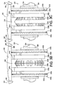
- Figures 4A-4C illustrate an alternate embodiment of a mechanism for expanding and collapsing the center section of a tire building drum.
- the linkage is capable of both expanding and contracting the expanding segments of the center section.
- Figures 4A-4C illustrate the major components of an expandable center section 420 (compare 320) of a tire building drum, according to an alternate embodiment of the invention.
- one of a plurality (e.g., 24) of expanding segments 428 (compare 328) is shown.
- the expanding segment is omitted, for illustrative clarity. It will be understood that the general alternating arrangement of fixed and expanding segments is substantially the same in this embodiment as in the previously-described embodiment.
- the fully-collapsed position of the center section 420 is shown in Figure 4A
- the fully-expanded position of the center section 420 is shown in Figure 4B.
- the drum may be expanded (or collapsed) to any position (diameter) between fully-collapsed and fully-expanded.
- a spindle (compare 308) extends along the axis 404 of the drum, but it omitted, for illustrative clarity.
- the center section is provided with fixed segments (e.g., 326), in the same (or similar) manner as was the previously-described embodiment.
- Two flanges 440a and 440b are disposed at axially spaced apart positions on the spindle.
- the flanges 440 are substantially similar to the flanges 340 of the previous embodiment, and are suitably in the form of generally planar discs which are centered on the axis (304), and are parallel with one another.
- Each guide element 440 has an inner surface which faces, and is parallel with the inner surface of the other guide element 440.
- the flanges 440 are essentially fixed to the spindle (308), which means that they will rotate with the spindle (308), and that they are at a fixed axial distance apart from one another.
- the inner surfaces of the flanges 440a and 440b are provided with a plurality of radially-extending grooves 442a and 442b and interspersed grooves 443a and 443b, respectively. Again, this is comparable to the grooves 342a and 342b and 343a and 343b of the previously-described embodiment.
- a given groove 442a on the guide plate 440a corresponds to, and is at the same circumferential position on the spindle as, a given groove 442b on the guide plate 440b.
- These two given grooves 442a, 442b form a pair of grooves and, for example, there are 24 pairs of grooves, spaced at even intervals about the inner surfaces of the flanges.
- Each pair of grooves functions as a track for guiding an expanding segment support, or base (support) element 448 (compare 348) as it moves radially inward or outward from the axis, as discussed hereinbelow.
- Each expanding segment 428 has a support element 448 associated therewith.
- the support element 448 is essentially a flat planar element having four edges (sides) - a top edge for supporting the expanding segment 328, a first side edge which rides in the groove 442a of a given groove pair, and a second side edge which rides in the groove 442b of the given groove pair.
- the support element 448 also has a bottom edge, but the shape of that edge is of no particular importance (as contrasted with the bottom edge ramp surface of the ramp element 348).
- the support element 448 is separate from the expanding segment 428, but it may also be integrally formed therewith. In the case that the support element 448 is not formed integrally with the expanding segment 428, the expanding segment 428 may be attached in any suitable manner to the support element 448.
- Two guide rings (hubs) 458a and 458b are disposed at axially spaced apart positions on the spindle (on either side of the centerplane).
- the guide rings 458 are suitably in the form of generally planar discs (rings, since they are discs with a hole in the middle) which are centered on the axis 404, and are parallel with one another.
- the guide rings 458 are not fixed to the spindle.
- An overlapping linkage mechanism 460 is provided between the guide rings 458 and the support element 448.
- the linkage mechanism comprises:
- the links 462 and 464 overlap each other (cross over one another), but are not pivotally attached to each other, as would be the case with a "scissors" type linkage, nor are they parallel to each other, as would be the case with a two-link “toggle” type linkage.
- Figure 4A (compare Figure 3B) the center section 420 is shown in its collapsed (or "fully-collapsed") position.
- the guide rings 458 are spread far apart from one another (essentially as far apart as they are capable of spreading), and the support element 448 and, consequently, the expanding segment 428 is at its minimal radial distance from the axis 404.
- the diameter of the center section 420 is at a minimum in this collapsed position.
- the outer surface of the center section 420 has substantially the same diameter as that of the outer surfaces (306) of adjacent end sections (322, 324).
- the inner liner of a tire carcass may be applied.
- the center section 420 is shown in its fully-expanded position. In this position, the guide rings 458 are close together (e.g., essentially zero distance apart from one another), and the support element 448 and, consequently, the expanding segment 428 is at its greatest greater radial distance from the axis 404. In other words, the center section 420 is now fully-expanded. In this fully-expanded position, the outer surface of the center section 420 has a much greater diameter than that of the outer surfaces (306) of adjacent end sections (e.g., 222, 224). Concurrently with the drum in the fully-expanded position, separately actuated bead locks (not shown) cause the beads to be firmly set.
- the ends of the carcass can then be turned up, in a final step of carcass construction.
- the center section 420 of the drum can be partially collapsed (e.g., returned to a semi-expanded position), the bead locks collapsed and the carcass can be removed for further processing, such as the application of a tread package in a second stage tire building machine.
- the links 462 and 464 are both nearly parallel to the axis 404. For example, at an angle of 19.6 degrees with respect thereto.
- the links 462 and 464 are at an angle approximately halfway between parallel to and perpendicular to the axis 303, such as at an angle of 46.2 degrees with respect thereto. This provides for a relatively compact mechanism with a good operating range.
- the center section can be expanded to any diameter between collapsed and fully-expanded, as determined by the spacing of the guide rings 458 from one another. For example, in a semi-expanded position, the ply of a tire carcass may be applied. It is preferred that the two guide rings 458 remain equidistant from the centerplane of the center section 420 of the drum while they are moving in their range of positions. In this manner, forces are evenly (symmetrically) distributed along the length ("L c ") of the support element 448 and the expanding segment 428.
- the relationship between guide ring spacing and center section diameter is inverse - the closer the guide rings are to one another, the greater the diameter of the center section.
- the relationship between guide rings spacing and center section diameter is direct - the closer the guide rings are to one another, the lesser the diameter of the center section.
- the diameter of the center section 320 and 420 is proportional (directly or inversely, respectively) to the spacing between the wedge elements 358 or guide rings 458, respectively.
- the overlapping linkage mechanism of Figures 4A-4C is superior to a toggle linkage, for example as shown in the aforementioned US-A- 4,929,298 with regard to being able to apply forces to the expanding segment in a manner which is symmetrical about the centerplane, throughout the range of expansion for the drum.
- a toggle linkage wherein two links move in unison parallel to one another, is inherently not symmetrical about the centerplane. This symmetry, as in the previous (wedge) embodiment, can be of profound significance in achieving uniformity in the layup of the tire carcass.
- the symmetry of forces exerted (urged) upon the expanding segments, about the centerplane, is non-trivial.
- a carcass ply which is lopsided (longer cords on one side of the tire than the other side) can cause a variety of tire nonuniformity problems including static imbalance and radial force variations.
- the present invention addresses one potential source of such nonuniformities - namely, imprecise (e.g., non-cylindrical) expansion of the drum.
- the surface of the drum when the center section (320, 420) is collapsed, the surface of the drum is substantially continuous, smooth, uninterrupted (flat), and this is advantageous for innerliner application.
- Means for providing a vacuum, through selected ones of the segments (either fixed or expanding), to the surface of the drum, to hold the innerliner securely thereon, may be provided, in any suitable manner.
- the center section When the center section is semi-expanded, the surface is also substantially flat, such as would be advantageous for ply application.
- Both embodiments can use a roller screw system for center section expansion.
- the mechanism for moving the wedges 358 or guide rings 458 depends largely on other factors present in the overall drum construction, and can be adapted on a case-by-case basis.
- the overlapping linkage design tends to provide more expansion range in a narrower width (L c ), allowing the minimum drum width to shrink, for example from 250mm (for the wedge embodiment) to 200 mm (for the linkage embodiment) .
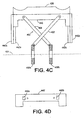
- Figure 4D illustrates an alternate embodiment of a support element 448' which is provided with two holes 442a and 442b (compare 342a and 342b) for receiving biasing members comparable to the biasing members 338 shown in Figures 3A-3D.
- the biasing members suitably in the form of rubber bands, would exert a "collapsing" radial force on the support element 448'.
- Figure 5 is a partial cross-sectional view of an exemplary tire carcass as it is laid up on a tire building drum, according to the invention. An end of an expanding segment 528 is shown. First, a center sleeve 502 is installed on the surface of the drum and extends over the expanding segment 528. An upper turnup bladder 503 and a lower turnup bladder 505 extends beyond the drum.
- the tire carcass comprises the following major components, in the following order:
- FIGS 1A and 1B illustrated beads 114 and 134 in place on a tire carcass being laid up on tire building drums 102 and 122, respectively.
- each bead 114 and 134 is a substantially inextensible, circular hoop, having an inside diameter ("ID") which is substantially equal to or preferably only slightly greater than the OD of the ply 112 or 132, respectively.
- ID inside diameter
- the beads 114 and 134 are shown as being installed slightly axially outboard of the inserts 110 and 130, respectively.
- Figures 2A through 2D illustrated a tire building drum 202 which is generally cylindrical, having two ends 202a and 202b, an axis of rotation 204 extending between the two ends, and a cylindrical outer surface 206.
- the drum 202 has a center section 220 which is generally cylindrical, and centered about the axis 204.
- the drum 202 has a first end section 222 which is coaxial with the center section 220, and which is disposed axially at one end of the center section 220.
- the drum 202 has a second end section 224 which is coaxial with the center section 220, and which is disposed axially at an opposite end of the center section 220.
- the two end sections 222 and 224 are substantially identical to (i.e., mirror images of) one another.
- the end sections 222 and 224 are axially-outward of the center section 220
- each end section includes a “bead lock assembly” which expands for setting the bead disposed on that section. This is discussed in greater detail hereinbelow.
- the center section of the drum is expandable, having (for example) a plurality of elongate fixed segments 226 alternating with a like plurality of elongate expanding segments 228.
- the beads are typically moved onto the respective end sections of the drum by using a bead holder which holds the bead and moves it into position about the carcass being laid up. The position at which the two beads are installed is approximately at the inner edge of the respective end section.
- FIGS 6A and 6B illustrate a bead holder 622 in a closed and open position, respectively.
- the bead holder 622 comprises a support (base) 602 and a ring 604.
- the ring 604 has an inside diameter "d".
- the ring 604 comprises three segments - a left segment 604a, a middle segment 604b and a right segment 604c.
- the three segments 604a, 604b and 604c are typically of equal arcuate extent - namely, approximately 120 degrees each.
- the middle segment 604b is fixed to the support 602.
- the left and right segments 604a and 604c are pivotally affixed to the middle segment 604b (as shown), or directly to the support 602.
- a mechanism 606 is provided for causing the left segment 604a to pivot from its closed position (Figure 6A) to its open position ( Figure 6B).
- a mechanism 607 is provided for causing the right segment 604a to pivot from its closed position ( Figure 6A) to its open position ( Figure 6B).
- the distal ends of the left and right segments 604a and 604c are spaced a distance apart "e" which is greater than the diameter (OD) of a tire drum (more particularly, of a carcass being laid up upon the drum), so that it can be removed from the drum simply by raising it (radially, with respect to the drum) off of the drum.
- This radial direction for removing the open bead holder 622 from a drum (not shown) having an axis 634 is indicated by the arrow 636.
- a plurality of magnets 608 are disposed just inside inner edge of the ring 604. These magnets are for holding a bead 612 (shown only partially, for illustrative clarity) onto the ring 604. The magnets 608 are strong enough to hold the bead 612, but weak enough to let the bead 612 stay in place on a drum, or on a tire carcass being laid up on the drum when the bead holder 622 is removed from the drum.
- a center sleeve 502 is installed on the surface of the drum and extends over the expanding segment 528 of the center section of the drum.
- Upper and lower turnup bladders 503 and 505 extend beyond an adjacent end section of the drum. The construction and operation of the turnup bladders are described in greater detail hereinbelow.
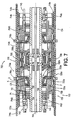
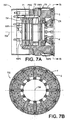
- FIG. 7 illustrates a fire building drum 700 (compare 202).
- the drum 700 is generally cylindrical, having two ends (compare 202a, 202b), an axis 704 (compare 204), and a generally cylindrical outer surface 706 (compare 206).
- the drum 700 has an overall axial length (compare "L") between the two ends.
- the drum 700 has a center section 720 (compare 220) which is generally cylindrical, and centered about the axis 704.
- the center section 720 has a width (compare "L c ").
- the drum 700 has a first end section 722 (compare 222) which is coaxial with the center section 720, and which is disposed axially at one end of the center section 720.
- the drum 700 has a second end section 724 (compare 224) which is coaxial with the center section 720, and which is disposed axially at an opposite end of the center section 720.
- the two end sections 722 and 274 are, for purposes of the present invention, substantially identical to (i.e., mirror images of) one another.
- the center section 720 is suitably circumferentially segmented, having a plurality of elongate fixed segments (not shown; compare 226) alternating with a like plurality of elongate expanding segments 728 (compare 228).
- the expanding segments 728 are axially-extending and circumferentially spaced from one another, and end portions of each is contoured to have annular recesses (pockets, grooves; compare 236a and 236b) in its outer surface at longitudinal (axial) positions corresponding to the positions of and related to the dimensions of sidewall inserts (e.g., 506, 510) which will be applied during the carcass layup process.
- the expanding segments 728 also have anchor points (compare 238a and 238b) for anchoring a center sleeve 713a, 713b which extends to the bladder 714a, 714b, respectively.
- anchor points compare 238a and 238b
- Exemplary dimensions for a tire building drum are set forth hereinabove.
- Exemplary dimensions for the end sections 722 and 724 may be extrapolated from dimensions of the center section 720, based on Figure 7.
- the center section 720 (220) is suitably expandable, between a collapsed (or retracted, or contracted) condition, and an expanded (or extended) condition (or “fully” expanded position), and various mechanisms for effecting expansion and collapse of the center section are described hereinabove, and the mechanisms accommodate partially expanding the center section to one (or more) “semi-expanded” (or semi-collapsed) positions. It has been discussed hereinabove that different tire components may be applied onto the tire carcass being laid up on the drum at different expansion positions (conditions) of the center section.
- Figure 7 illustrates two end sections 722 and 724, one at each end of the center section 720.
- the end sections 722,724 are provided with expandable bead lock assemblies 726a,726b, including mechanisms for expanding the bead lock assemblies for applying selected tire components (e.g., beads) onto the tire carcass being laid up on the drum at different expansion positions (conditions) of the end sections, as described in greater detail hereinbelow. Since the two end sections are essentially mirror-images of one another, it is sufficient to describe only one of the end sections in detail.
- Figure 7 also illustrates turnup bladders disposed on the end sections 722,724.
- a bottom turnup bladder 712a is disposed on the outer surface of the end section 722.
- a bottom turnup bladder 712b is disposed on the outer surface of the end section 724.
- a top turnup bladder 714a is disposed over the bottom turnup bladder 712a on the outer surface of the end section 722.
- a top turnup bladder 714b is disposed over the bottom turnup bladder 712b on the outer surface of the end section 724.
- the turnup bladders 712a/b and 714a/b are for turning up turnup ends of the green carcass around respective beads 734a and 734b (compare 134a and 134b; also 512).
- Each of the end sections 722 and 724 is provided with a bead lock assembly 726a, 726b (collectively "726"). Since the end sections 722 and 724 are substantially “mirror images" of one another, it is sufficient to describe the bead lock assembly 726 of only a single end section 722 in detail.
- a bead lock assembly 726a comprises the following major components:
- the pistons P1 and P2 are each generally in the form of flat discs, both centered on the axis 704 (hence, "coaxial"), and each having substantially the same outer diameter as the other.
- the axis 704 is normal to the planes of the pistons P1 and P2.
- the pistons P1 and P2 are disposed in a cylinder block (or simply “cylinder") 730, a cylindrical interior portion 732 ("piston portion") of which has an inner diameter corresponding to the outer diameter of the pistons P1 and P2.
- the pistons P1 and P2 are disposed in this piston portion 732 of the cylinder 730, and are free to move axially inward and outward (with reference to the center section 720) therein.
- the first piston P1 is disposed axially outward (away from the center section 720) of the second piston P2.
- the second piston P2 is thus disposed axially inward of the first piston P1.
- the two pistons P1 and P2 are shown abutting one another, and the bead lock assembly 726 is in its collapsed position.
- the two pistons P1 and P2 are axially movable, and when they move, they impart axial movement to the carrier ring CR.
- the plurality of links (link arms) "K" extend between the carrier ring CR and radially inner ends of the expandable segments S.
- One end of a link K is pivotably connected to the carrier ring CR, the other end is pivotably connected to a radially inner end of an expandable segment S.
- the expandable segments S are constrained from axial movement, and limited to radial movement. When the carrier ring CR moves axially inward (towards the center section 720), the expandable segments S move radially outwardly. In a corollary manner, when the carrier ring CR moves axially outward (sway from the center section), the expandable segments S move radially inwardly.
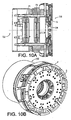
- the expandable segments S are elongate, and suitably substantially square in cross-section (see, e.g., Figure 10B).
- An end plate 734 is disposed at the outer end of the cylinder 730 - more particularly, at the outer end of the piston portion 732 of the cylinder 730.
- This end plate 734 defines the outer end of the piston portion 732, closing it off and establishing a limit to outward movement of the pistons P1 and P2. It also seals off the outer end of the piston portion 732.
- An annular projection 736 extends from the inner surface of the cylinder 730 at a position spaced axially inward from the end plate 734, and defines an inner end of the piston portion 732.
- This annular projection 736 establishes a limit to inward movement of the pistons P1 and P2.
- the pistons P1 and P2 are free to move axially, in the piston portion 732 of the cylinder, between the end plate 734 and the annular projection 736. In this manner, an airtight piston portion 732 is defined.
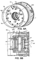
- Two pneumatic (e.g., air) lines 742 and 744 are shown in Figure 7, both of which have an end terminating in the end plate 734, are disposed at the outer end of the cylinder 730. As described hereinbelow, pressure in these lines 742 and 744, in conjunction with a third line 745 (best seen in Figure 8A) control movement of the pistons P1 and P2.
- pneumatic line 744 directs pressurized air through air passageway PW1 behind piston P1.
- Pneumatic line 742 directs pressurized air through air passageway PW2 between pistons P1 and P2.
- pneumatic line 742 directs pressurized air through an unseen passageway air PW3 between piston P2 and annular projection 736.
- the expandable segments S are constrained from axial movement, and are limited to radial movement. As illustrated in Figure 7, the expandable segments S move radially in a radial channel which is formed between the inward (towards the center section 720) end 730a of a cylinder 731 a and an end plate 723a at the inward end 722a of the end section 722.
- the expandable segments S are suitably in the form of square elongate shafts.
- Finger segments "F" which are circumferential segments are disposed at the radially outer ends of the expandable segments S. There are a plurality, such as twelve, expandable segments S, and a like plurality, such as twelve, finger segments F.
- the finger segments F are spaced partially, such as at about 30 degrees, about the circumference of the end section 722.
- Figures 7A, 7B, 8A and 8B illustrate the end section 722 of the tire building drum 700, in a fully-collapsed condition. This is somewhat analogous to the situation where, in Figure 3, the center section (220) was shown in a fully-collapsed condition.
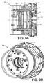
- Figures 9A and 9B illustrate the end section 722 of the tire building drum 700, in a semi-expanded (or semi-collapsed) condition. This is somewhat analogous to the situation where, in Figure 3C, the center section (220) was shown in a semi-expanded (or semi-collapsed) condition.
- Figures 10A and 10B illustrate the end section 722 of the tire building drum 700, in a fully-expanded condition. This is somewhat analogous to the situation where, in Figure 3D, the center section (220) was shown in a fully-expanded condition.
- the mechanical components of the bead lock assembly 726 include:
- the bead lock assembly 726 further comprises the following mechanical components:
- Three pneumatic lines 742, 743 and 744 are provided, along with associated passageways PW1, PW2 and PW3 in the cylinder block (730) for providing pressurized air at the following locations:
- a first expansion step in a first expansion step (semi-expanded), pressurized air is provided through the line 744, through the passageway PW1 to the outer surface of the piston P1.
- This causes the piston P1 to move axially inward, towards the center section 720.
- the piston P1 moves inward, it pushes the piston P2 inward.
- Inward axial movement of the piston P1 is limited by three rods R1P1, R2P1, R3P1 extending through the end plate 734 into the piston P1, as described below.
- Three rods R1P2, R2P2, R3P2 extend axially between piston P2 and the carrier ring CR.
- the carrier ring CR moves inward.
- the elongate links K extend between the carrier ring CR and the expandable segments S.
- the expanding segments S move radially outward.
- the plurality of finger segments F are disposed at the outer ends of the elongate expanding segments S.
- the finger segments F move radially outward to a second radius, larger than the first, the diameter of the bead lock assembly 726 in the end section 722 is increased.
- pressurized air is provided in the line 744, the bead lock assembly 726 becomes partially expanded.
- the three rods R1P1, R2P1, R3P1 extend through the end plate 734 into the piston P1, preferably at evenly spaced circumferential positions (120 degrees) about the axis 704. In conjunction with a stop block B1, these rods limit the inward axial movement of the piston P1. This is the intermediate, partially-expanded condition of the bead lock assembly 726. To adjust the intermediate position, different length stop blocks B1 can be used.
- Retraction of the bead lock assembly 726 is accomplished by providing pressurized air though the line 743 into the passageway PW3 (see Figure 7A) to the axially inward side of the piston P2.
- the pressurized air in lines 742 and 744 is stopped.
- the pressurized air in line 743 causes the piston P2 to move axially outward, thereby via the rods R1P2, R2P2, R3P2 moving the carrier ring CR axially outward, thereby via the links K moving the expandable segments S and finger segments F radially inward, thereby decreasing the diameter of the bead lock assembly 726 to its fully-collapsed condition.
- the piston P2 moves axially outward until it is stopped by the piston P1.
- the piston P1 had been restrained from retracting, in its intermediate position, it could be selectively maintained in the unretracted position, and the axially outward movement of the piston P2 would be limited by the piston P1, thereby establishing a partially-collapsed condition for the bead lock assembly, after which by allowing the piston P1 to retract fully, the piston P2 could move further axially outward to allow the bead lock assembly to achieve its fully- collapsed condition.
- end section 722 (and, of course, the end section 724) can selectively and controllably be expanded and collapsed.
- the center section 720 essentially the entire outer surface of which can be expanded and collapsed, it is only a small segment of the end sections 722,724 that is expanded and collapsed, namely a band defined by the plurality of finger segments F.
- the band defined by the segments F extends axially from an inner end of the respective end section 722,724 towards the outer end thereof, and circumferentially entirely around the end section.
- the finger segments F is expandable from a first radius in a collapsed condition of the end sections 722,724 of the drum to a second radius in an intermediate, partially-expanded condition and then to a third radius in a fully expanded condition of the end sections of the drum.
- pressurized air supplied through the first passage 744 via the first passageway PW1 to an outer side of the first piston P1 causes the first piston P1 to move axially inward, pushing the second piston P2 also axially inward, until constrained by the rods R1P1,R2P1,R3P1, so that the bead lock assembly 726 is partially-expanded.
- Pressurized air supplied through the third passage 743 via the third passageway PW3 to a location on the inner side of the second piston P2 causes the second piston P2 to move axially outward, so that the bead lock assembly 726 is fully collapsed unless stopped by the first piston P1 as discussed above.
Claims (10)
- Eine Reifenbautrommel (700) mit einer Achse (704), einem zentralen Abschnitt (720) und zwei Endabschnitten (722, 724), wobei die Trommel dadurch gekennzeichnet ist, dass:jeder Endabschnitt mit einer ausdehnbaren Wulstriegelmontageeinheit (726) mit einer Vielzahl von sich axial erstreckenden, in Umfangsrichtung voneinander beabstandeten Fingersegmenten (F), die zum Greifen eines Wulsts (514) angepasst sind, versehen ist ;jedes der Fingersegmente von einem ersten Fingerradius in einem zusammengezogenen zustand der Wulstriegelmontageeinheit zu einem zweiten Fingerradius in einem halb ausgedehnten Zustand der Wulstriegelmontageeinheit und zu einem dritten Fingerradius in einem vollständig ausgedehnten Zustand der Wulstriegelmontageeinheit ausdehnbar ist.
- Die Reifenbautrommel gemäß Anspruch 1, wobei jede Wulstriegelmontageeinheit folgendes umfasst:wobei die Fingersegmente (F) an radial äußeren Enden der ausdehnbaren Segmente (S) angeordnet sind ; undeinen Trägerring (CR) ;eine Vielzahl radial ausdehnbarer Segmente (S) ; undeine Vielzahl länglicher Verbindungsglieder (K), die sich zwischen dem Trägerring und radial inneren Enden der ausdehnbaren Segmente (S) erstrecken ;
wobei die axiale Bewegung des Trägerrings (CR) eine radiale Bewegung der ausdehnbaren Segmente (S) und der Fingerelemente verursacht. - Die Reifenbautrommel gemäß Anspruch 2, weiterhin umfassend:wobei die axiale Bewegung des zweiten Kolbens eine axiale Bewegung des Trägerrings verursacht.einen Zylinder (730) mit einem zylindrischen Kolbenteil (732) ;einen in dem Kolbenteil angeordneten ersten Kolben (P1) ;einen in dem Kolbenteil angeordneten zweiten Kolben (P2) ; undzumindest eine Stange (R1P2, R2P2, R3P2), die den zweiten Kolben mit dem Trägerring verbindet ;
- Die Reifenbautrommel gemäß Anspruch 3, weiterhin umfassend:zumindest eine Stange (R1P1, R2P1, R3P1), die sich von dem ersten Kolben (P1) durch eine Endplatte (734) des Zylinders (730) erstreckt, zur Begrenzung der axialen Bewegung des ersten Kolbens (P1).
- Die Reifenbautrommel gemäß Anspruch 4, weiterhin umfassend:wobei die Kolben durch selektives Anlegen von Druckluft in den Pneumatikleitungen axial innerhalb des Kolbenteils des Zylinders bewegt werden können.Pneumatikleitungen (742,743,744), die an Durchgangswege (PW1,PW2,PW3) innerhalb des Zylinders anschließen ;
- Die Reifenbautrommel gemäß Anspruch 5, wobei:der erste Kolben und der zweite Kolben jeder generell in Form flacher Scheiben vorliegen und beide auf der Achse zentriert sind und jeder im Wesentlichen denselben Außendurchmesser hat wie der andere.
- Die Reifenbautrommel gemäß Anspruch 1, wobei:der zentrale Abschnitt in Umfangsrichtung segmentiert ist, wobei er eine Vielzahl länglicher fester Segmente (226) aufweist, die mit einer gleichen Vielzahl länglicher, sich ausdehnender Segmente (728) abwechseln.
- Die Reifenbautrommel gemäß Anspruch 7, wobei:die sich ausdehnenden Segmente sich axial erstrecken und in Umfangsrichtung voneinander beabstandet sind, und Endbereiche der sich ausdehnenden Segmente mit einer Kontur versehen sind, um ringförmige Aussparungen (236) in ihren Außenflächen zu haben, an Positionen, die den Positionen von Seitenwandeinsätzen (506, 510) entsprechen, die an einer auf der Trommel aufgelegten Reifenkarkasse angebracht werden ; undjedes der sich ausdehnenden Segmente an einem ersten Trommelradius positioniert ist, wenn die Trommel in dem zusammengezogenen Zustand ist, an einem zweiten Trommelradius, wenn die Trommel in dem halb ausgedehnten Zustand ist, und an einem dritten Trommelradius, wenn die Trommel sich in dem vollständig ausgedehnten Zustand befindet.
- Der Vorgang des Bauens eines Reifens auf einer Reifenbautrommel (700) mit einem ausdehnbaren zentralen Abschnitt (720) und zwei ausdehnbaren Endabschnitten (722, 724), gekennzeichnet durch die Schritte des:(a) Anbringens einer Innenisolierung (504) auf einer flachen Anbringfläche der Reifenbautrommel, während die Bautrommel und die Endabschnitte in ihren zusammengezogenen, unausgedehnten Zuständen sind ;(b) Ausdehnens sowohl des zentralen Abschnitts (720) als auch der Endabschnitte (722, 724) auf ihre ausgedehnten Zwischenzustände ;(c) Anbringens von Pfeilereinsätzen (506), gefolgt von einer ersten Karkassenlage (508), gefolgt von Pfosteneinsätzen (510), gefolgt von einer zweiten Karkassenlage (512), auf dem zentralen Abschnitt ;(d) Bewegens eines Paars Wülste (514) an Ort und Stelle über einer Wulstriegelmontageeinheit (726) in jedem der ausdehnbaren Endabschnitte (726) ;(e) Ausdehnens jeder der Wulstriegelmontageeinheiten und des zentralen Abschnitts (720) auf ihre vollständig ausgedehnten Positionen, sodass die Wülste an ihrem Platz gesichert werden ;(f) Umschlagens der Innenisolierung, ersten Karkassenlage und zweiten Karkassenlage um die Wülste ;(g) Zusammenziehens der Wulstriegelmontageeinheiten (726) und des zentralen Abschnitts (720) in die zusammengezogene Position ; und(h) Entfernens einer vervollständigten Rohreifenkarkasse von der Trommel.
- Der Vorgang des Bauens eines Reifens auf einer Reifenbautrommel gemäß Anspruch 9, weiter umfassend:in Schritt (b) das Formen eines Paars beabstandeter Aussparungen am zentralen Abschnitt der Trommel ; undin Schritt (c) das Anbringen der Pfeilereinsätze in den Aussparungen.
Applications Claiming Priority (2)
| Application Number | Priority Date | Filing Date | Title |
|---|---|---|---|
| US960211 | 2001-09-21 | ||
| US09/960,211 US6769468B2 (en) | 2001-09-21 | 2001-09-21 | Tire building drum having expandable center section and independently expandable bead lock assemblies in the end sections |
Publications (3)
| Publication Number | Publication Date |
|---|---|
| EP1295702A2 EP1295702A2 (de) | 2003-03-26 |
| EP1295702A3 EP1295702A3 (de) | 2004-01-14 |
| EP1295702B1 true EP1295702B1 (de) | 2005-10-05 |
Family
ID=25502944
Family Applications (1)
| Application Number | Title | Priority Date | Filing Date |
|---|---|---|---|
| EP02021255A Expired - Fee Related EP1295702B1 (de) | 2001-09-21 | 2002-09-19 | Reifenaufbautrommel mit einem Mittelteil und Endteilen, die unabhängig voneinander ausdehnbar sind |
Country Status (11)
| Country | Link |
|---|---|
| US (2) | US6769468B2 (de) |
| EP (1) | EP1295702B1 (de) |
| JP (1) | JP4559695B2 (de) |
| KR (1) | KR100913651B1 (de) |
| CN (1) | CN100421917C (de) |
| AU (1) | AU2002301010B2 (de) |
| BR (1) | BR0203720B1 (de) |
| CA (1) | CA2404211C (de) |
| DE (1) | DE60206456T2 (de) |
| ES (1) | ES2250564T3 (de) |
| MX (1) | MXPA02008786A (de) |
Families Citing this family (44)
| Publication number | Priority date | Publication date | Assignee | Title |
|---|---|---|---|---|
| US7001163B2 (en) * | 2003-02-11 | 2006-02-21 | The Goodyear Tire & Rubber Company | Mold and method of molding annular tread |
| JPWO2004103688A1 (ja) * | 2003-05-20 | 2006-07-20 | 横浜ゴム株式会社 | 空気入りラジアルタイヤの製造方法 |
| JP4301883B2 (ja) | 2003-07-29 | 2009-07-22 | 株式会社ブリヂストン | タイヤの製造方法およびタイヤ |
| KR100594847B1 (ko) * | 2004-09-21 | 2006-06-30 | 한국타이어 주식회사 | 타이어 비드 포머의 나비드 분리장치 |
| US7344614B2 (en) * | 2004-11-01 | 2008-03-18 | The Goodyear Tire & Rubber Company | Tire breaker strip application method and tire fabricated therefrom |
| US7288160B2 (en) * | 2004-12-23 | 2007-10-30 | The Goodyear Tire & Rubber Company | Method of making a tire using a high crown uni-stage tire building drum |
| US7287568B2 (en) * | 2004-12-23 | 2007-10-30 | The Goodyear Tire & Rubber Company | High crown uni-stage tire building drum |
| JP4626420B2 (ja) * | 2005-06-29 | 2011-02-09 | 横浜ゴム株式会社 | 成形ドラム及び筒状部材の成形方法 |
| DE602007000888D1 (de) * | 2006-06-16 | 2009-05-28 | Michelin Soc Tech | Verfahren zum Auflegen einer verstärkten Karkassenlage. |
| JP4733710B2 (ja) * | 2008-01-22 | 2011-07-27 | 住友ゴム工業株式会社 | シェーピングフォーマ |
| DE102008032382B3 (de) * | 2008-07-09 | 2009-12-17 | Continental Aktiengesellschaft | Vorrichtung zum Zusammenfügen eines mit einem Kernreiter versehenen Reifenkernes mit einem Wulstverstärker auf einer Aufbautrommel |
| DE102008037535A1 (de) * | 2008-11-10 | 2010-05-12 | Continental Reifen Deutschland Gmbh | Vorrichtung zum Aufbau einer Reifenkarkasse für einen Fahrzeugreifen |
| US8662122B2 (en) * | 2010-05-14 | 2014-03-04 | The Goodyear Tire & Rubber Company | System for non-pneumatic support of a vehicle |
| US8555944B2 (en) * | 2010-07-09 | 2013-10-15 | Davian Enterprises, LLC | Anti-flex assembly |
| EP2670608B1 (de) | 2011-02-01 | 2017-03-15 | ExxonMobil Chemical Patents Inc. | Profilierte reifenkappen und herstellungsverfahren dafür |
| JP5281671B2 (ja) * | 2011-05-12 | 2013-09-04 | 住友ゴム工業株式会社 | ランフラットタイヤ用のシェーピングフォーマ |
| US9193122B2 (en) * | 2011-09-26 | 2015-11-24 | The Goodyear Tire & Rubber Company | Solid deck bead lock drum |
| FR2981293B1 (fr) * | 2011-10-14 | 2017-02-10 | Soc De Tech Michelin | Tambour de fabrication de pneumatique comprenant des secteurs mobiles |
| US9908302B2 (en) | 2012-06-21 | 2018-03-06 | Compagnie Generale Des Etablissements Michelin | Method for adhering an innerliner to a carcass ply of a tire |
| US20140048213A1 (en) * | 2012-08-15 | 2014-02-20 | The Goodyear Tire & Rubber Company | Sleeveless tire building drum with interchangeable width elements |
| DE102012109739A1 (de) * | 2012-10-12 | 2014-04-17 | Continental Reifen Deutschland Gmbh | Verfahren zur Herstellung eines Fahrzeugreifens |
| FR3009233B1 (fr) | 2013-08-01 | 2016-01-01 | Michelin & Cie | Tambour de confection d'une bande de roulement muni de secteurs mobiles |
| FR3009232B1 (fr) * | 2013-08-01 | 2016-01-01 | Michelin & Cie | Tambour de confection d'une bande de roulement muni de secteurs retractables |
| JP6153845B2 (ja) * | 2013-10-25 | 2017-06-28 | 東洋ゴム工業株式会社 | タイヤ成型ドラム用スリーブ、タイヤ成型装置、及びタイヤ成型方法 |
| EP3174701B1 (de) * | 2014-07-29 | 2020-10-28 | Pirelli Tyre S.p.A. | Vorrichtung und verfahren zur herstellung von reifen für fahrzeugräder |
| CN105774007A (zh) * | 2014-12-26 | 2016-07-20 | 鼎汉科技(厦门)有限公司 | 一种用于轮胎成型可膨胀收缩的布圈鼓装置 |
| US10611112B2 (en) | 2016-07-22 | 2020-04-07 | The Goodyear Tire & Rubber Company | Center mechanism for tire building drum |
| WO2018228624A1 (de) * | 2017-06-16 | 2018-12-20 | Harburg-Freudenberger Maschinenbau Gmbh | Verfahren und vorrichtung zur herstellung von reifen |
| US20190070814A1 (en) * | 2017-09-01 | 2019-03-07 | The Goodyear Tire & Rubber Company | Method of building tires |
| JP6648771B2 (ja) * | 2018-02-16 | 2020-02-14 | 横浜ゴム株式会社 | タイヤの製造方法 |
| EP3581355B1 (de) * | 2018-06-12 | 2020-12-16 | Tetra Laval Holdings & Finance S.A. | Formvorrichtung zum spritzgiessen einer öffnungsvorrichtung auf ein blatt aus verpackungsmaterial |
| NL2021842B1 (en) * | 2018-10-19 | 2020-05-13 | Vmi Holland Bv | Tire building drum and method for tire building |
| IT201800011018A1 (it) * | 2018-12-12 | 2020-06-12 | Marangoni Mecc S P A | Gruppo di formatura per la formatura di una carcassa di un penumatico |
| CN113518705B (zh) * | 2019-01-28 | 2023-10-20 | 达维阶企业有限责任公司 | 带反向偏离指状件的可扩展带束层和胎面鼓 |
| CN109878121A (zh) * | 2019-03-07 | 2019-06-14 | 江阴市勤力橡塑机械有限公司 | 一种三鼓式全钢宽基胎的一次成型工艺 |
| CN110202809A (zh) * | 2019-07-01 | 2019-09-06 | 萨驰华辰机械(苏州)有限公司 | 一种轮胎成型鼓 |
| FR3099407B1 (fr) * | 2019-08-01 | 2021-07-02 | Michelin & Cie | Tambour expansible pour la conformation de bandages pneumatiques comprenant un dispositif extenseur a parallélogramme pour le maintien de la tringle |
| IT201900023616A1 (it) * | 2019-12-11 | 2021-06-11 | Pirelli | Tamburo di formatura per la produzione di pneumatici per ruote di veicoli e metodo per controllare la geometria di un tamburo di formatura per la produzione di pneumatici per ruote di veicoli |
| CN111319284B (zh) * | 2020-04-09 | 2022-01-28 | 烟台富瑞达机械有限公司 | 一种双工位实心胎成型设备 |
| CN111976181A (zh) * | 2020-08-06 | 2020-11-24 | 北京敬业机械设备有限公司 | 半钢子午胎二次法平鼓贴合一段成型机 |
| CN112388999B (zh) * | 2020-10-30 | 2022-11-11 | 潍坊市跃龙橡胶有限公司 | 一种全钢一次法三鼓成型机的贴合鼓贴合工艺 |
| KR102422508B1 (ko) * | 2020-11-30 | 2022-07-20 | 주식회사 동방엔지니어링 | 다단확장기능을 갖는 타이어 성형드럼 |
| CN113635584B (zh) * | 2021-10-12 | 2021-12-31 | 天津赛象科技股份有限公司 | 一种可变工作直径的成型鼓 |
| CN113910832A (zh) * | 2021-11-22 | 2022-01-11 | 三角轮胎股份有限公司 | 子午线航空轮胎 |
Family Cites Families (22)
| Publication number | Priority date | Publication date | Assignee | Title |
|---|---|---|---|---|
| US3038526A (en) * | 1958-06-05 | 1962-06-12 | Firestone Tire & Rubber Co | Tire building drum |
| DE1240267B (de) * | 1962-01-13 | 1967-05-11 | Continental Gummi Werke Ag | Segmenttrommel zum Aufbauen von Luftreifen |
| DE1579145B1 (de) * | 1965-08-25 | 1972-02-03 | Continental Gummi Werke Ag | Maschine zum Aufbauen von Luftreifenrohlingen |
| US3816218A (en) * | 1972-03-29 | 1974-06-11 | Goodyear Tire & Rubber | Tire building drum |
| US3837968A (en) * | 1972-11-20 | 1974-09-24 | Goodyear Tire & Rubber | Tire building drum |
| CA1062594A (en) * | 1974-05-22 | 1979-09-18 | Frank R. Jellison | Building machine having an infinite number of drum settings |
| US4239579A (en) * | 1979-05-25 | 1980-12-16 | The Goodyear Tire & Rubber Company | Tire building drum |
| US4855008A (en) * | 1988-05-09 | 1989-08-08 | The Goodyear Tire & Rubber Company | Expandable tire building drum |
| US4929298A (en) | 1988-05-13 | 1990-05-29 | The Goodyear Tire & Rubber Company | Tire building drum including an expandable segmental cylinder assembly and a vacuum chamber |
| US4976804A (en) | 1989-05-05 | 1990-12-11 | The Goodyear Tire & Rubber Company | Expandable tire building drum |
| JPH0645194B2 (ja) * | 1990-07-24 | 1994-06-15 | 住友ゴム工業株式会社 | 生タイヤ成形機におけるビードロック方法及びその装置 |
| JPH0757537B2 (ja) * | 1991-03-20 | 1995-06-21 | 株式会社森鐵工所 | タイヤ成型ドラム装置における可動部を駆動するための装置およびそれを使用したタイヤ成型ドラム装置 |
| JPH07102628B2 (ja) | 1991-04-30 | 1995-11-08 | 住友ゴム工業株式会社 | 環状部材成形装置 |
| JP3157543B2 (ja) * | 1991-05-29 | 2001-04-16 | 株式会社ブリヂストン | ビードロック装置およびこれを用いたビードロック方法 |
| US5433814A (en) * | 1992-06-29 | 1995-07-18 | Yasushi Nojiri | Green tire building apparatus |
| CA2121159C (en) | 1993-07-16 | 2005-03-29 | Kenneth Dean Conger | Contoured tire building drum and method of building an extended mobility tire |
| US5405484A (en) * | 1994-03-22 | 1995-04-11 | Bridgestone/Firestone, Inc. | Tire building drum |
| JP3736968B2 (ja) * | 1998-04-28 | 2006-01-18 | 株式会社ブリヂストン | 空気入りタイヤの製造方法 |
| US6058999A (en) * | 1998-05-04 | 2000-05-09 | Wyko, Inc. | Tire manufacturing drum having simultaneous axial and radial adjustability |
| IT1303143B1 (it) * | 1998-07-10 | 2000-10-30 | Bridgestone Firestone Tech | Tamburo unistadio per la formatura di pneumatici |
| US6343638B1 (en) * | 2000-02-23 | 2002-02-05 | The Goodyear Tire & Rubber Company | Tire belt folding drum |
| US6863106B2 (en) * | 2001-09-21 | 2005-03-08 | The Goodyear Tire & Rubber Company | Expandable tire building drum with alternating fixed and expandable segments, and contours for sidewall inserts |
-
2001
- 2001-09-21 US US09/960,211 patent/US6769468B2/en not_active Expired - Fee Related
-
2002
- 2002-09-09 MX MXPA02008786A patent/MXPA02008786A/es active IP Right Grant
- 2002-09-12 BR BRPI0203720-3A patent/BR0203720B1/pt not_active IP Right Cessation
- 2002-09-13 AU AU2002301010A patent/AU2002301010B2/en not_active Ceased
- 2002-09-18 KR KR1020020056993A patent/KR100913651B1/ko active IP Right Grant
- 2002-09-19 DE DE60206456T patent/DE60206456T2/de not_active Expired - Lifetime
- 2002-09-19 CA CA2404211A patent/CA2404211C/en not_active Expired - Fee Related
- 2002-09-19 ES ES02021255T patent/ES2250564T3/es not_active Expired - Lifetime
- 2002-09-19 EP EP02021255A patent/EP1295702B1/de not_active Expired - Fee Related
- 2002-09-23 CN CNB021425108A patent/CN100421917C/zh not_active Expired - Fee Related
- 2002-09-24 JP JP2002277983A patent/JP4559695B2/ja not_active Expired - Fee Related
-
2004
- 2004-06-07 US US10/862,691 patent/US7144467B2/en not_active Expired - Fee Related
Also Published As
| Publication number | Publication date |
|---|---|
| US6769468B2 (en) | 2004-08-03 |
| KR20030025847A (ko) | 2003-03-29 |
| BR0203720B1 (pt) | 2010-11-16 |
| AU2002301010B2 (en) | 2007-06-28 |
| EP1295702A3 (de) | 2004-01-14 |
| US7144467B2 (en) | 2006-12-05 |
| MXPA02008786A (es) | 2003-03-27 |
| KR100913651B1 (ko) | 2009-08-24 |
| CN100421917C (zh) | 2008-10-01 |
| US20040216831A1 (en) | 2004-11-04 |
| CA2404211A1 (en) | 2003-03-21 |
| US20030056879A1 (en) | 2003-03-27 |
| DE60206456T2 (de) | 2006-06-22 |
| BR0203720A (pt) | 2003-06-03 |
| ES2250564T3 (es) | 2006-04-16 |
| CA2404211C (en) | 2010-07-27 |
| DE60206456D1 (de) | 2006-02-16 |
| JP2003159758A (ja) | 2003-06-03 |
| CN1410256A (zh) | 2003-04-16 |
| JP4559695B2 (ja) | 2010-10-13 |
| EP1295702A2 (de) | 2003-03-26 |
Similar Documents
| Publication | Publication Date | Title |
|---|---|---|
| EP1295702B1 (de) | Reifenaufbautrommel mit einem Mittelteil und Endteilen, die unabhängig voneinander ausdehnbar sind | |
| AU2002301012B2 (en) | Expandable Tire Building Drum with Alternating Fixed and Expandable Segments, and Contours for Sidewall Inserts | |
| EP1674248B1 (de) | Eine einen hohen Scheitel aufweisende Einstufen-Aufbautrommel für Reifen | |
| EP1674249B1 (de) | Verfahren zur Herstellung eines Reifens unter Verwendung einer einen hohen Scheitel aufweisenden Einstufen-Aufbautrommel für Reifen | |
| US20060219348A1 (en) | Method for manufacturing tires on a flexible manufacturing system | |
| EP1504883B1 (de) | Eine einen hohen Scheitel aufweisende Aufbautrommel zur Herstellung einer erststufigen Karkasse | |
| US20150059962A1 (en) | Method of building a tire | |
| US6773530B2 (en) | Method for manufacturing tires on a flexible manufacturing system | |
| US20150059984A1 (en) | Tire building drum | |
| EP2698244A1 (de) | Manschettenlose Reifenbautrommel mit auswechselbaren Breitenelementen | |
| EP0302935B1 (de) | Radialreifen für flugzeug und dessen herstellung | |
| RU2373056C2 (ru) | Способ и устройство для изготовления шин для колес транспортных средств |
Legal Events
| Date | Code | Title | Description |
|---|---|---|---|
| PUAI | Public reference made under article 153(3) epc to a published international application that has entered the european phase |
Free format text: ORIGINAL CODE: 0009012 |
|
| AK | Designated contracting states |
Kind code of ref document: A2 Designated state(s): AT BE BG CH CY CZ DE DK EE ES FI FR GB GR IE IT LI LU MC NL PT SE SK TR |
|
| AX | Request for extension of the european patent |
Extension state: AL LT LV MK RO SI |
|
| PUAL | Search report despatched |
Free format text: ORIGINAL CODE: 0009013 |
|
| AK | Designated contracting states |
Kind code of ref document: A3 Designated state(s): AT BE BG CH CY CZ DE DK EE ES FI FR GB GR IE IT LI LU MC NL PT SE SK TR |
|
| AX | Request for extension of the european patent |
Extension state: AL LT LV MK RO SI |
|
| RIC1 | Information provided on ipc code assigned before grant |
Ipc: 7B 29D 30/24 A Ipc: 7B 29D 30/20 B Ipc: 7B 29D 30/36 B |
|
| 17P | Request for examination filed |
Effective date: 20040714 |
|
| 17Q | First examination report despatched |
Effective date: 20040810 |
|
| AKX | Designation fees paid |
Designated state(s): DE ES FR GB IT NL |
|
| GRAP | Despatch of communication of intention to grant a patent |
Free format text: ORIGINAL CODE: EPIDOSNIGR1 |
|
| RIN1 | Information on inventor provided before grant (corrected) |
Inventor name: REDING, EMILE Inventor name: ROEDSETH, JOHN KOLBJOERN Inventor name: CURRIE, WILLIAM DUDLEY |
|
| GRAS | Grant fee paid |
Free format text: ORIGINAL CODE: EPIDOSNIGR3 |
|
| GRAA | (expected) grant |
Free format text: ORIGINAL CODE: 0009210 |
|
| AK | Designated contracting states |
Kind code of ref document: B1 Designated state(s): DE ES FR GB IT NL |
|
| PG25 | Lapsed in a contracting state [announced via postgrant information from national office to epo] |
Ref country code: NL Free format text: LAPSE BECAUSE OF FAILURE TO SUBMIT A TRANSLATION OF THE DESCRIPTION OR TO PAY THE FEE WITHIN THE PRESCRIBED TIME-LIMIT Effective date: 20051005 |
|
| REG | Reference to a national code |
Ref country code: GB Ref legal event code: FG4D |
|
| REF | Corresponds to: |
Ref document number: 60206456 Country of ref document: DE Date of ref document: 20060216 Kind code of ref document: P |
|
| NLV1 | Nl: lapsed or annulled due to failure to fulfill the requirements of art. 29p and 29m of the patents act | ||
| REG | Reference to a national code |
Ref country code: ES Ref legal event code: FG2A Ref document number: 2250564 Country of ref document: ES Kind code of ref document: T3 |
|
| ET | Fr: translation filed | ||
| PLBE | No opposition filed within time limit |
Free format text: ORIGINAL CODE: 0009261 |
|
| STAA | Information on the status of an ep patent application or granted ep patent |
Free format text: STATUS: NO OPPOSITION FILED WITHIN TIME LIMIT |
|
| 26N | No opposition filed |
Effective date: 20060706 |
|
| PGFP | Annual fee paid to national office [announced via postgrant information from national office to epo] |
Ref country code: GB Payment date: 20070809 Year of fee payment: 6 |
|
| GBPC | Gb: european patent ceased through non-payment of renewal fee |
Effective date: 20080919 |
|
| PG25 | Lapsed in a contracting state [announced via postgrant information from national office to epo] |
Ref country code: GB Free format text: LAPSE BECAUSE OF NON-PAYMENT OF DUE FEES Effective date: 20080919 |
|
| PGFP | Annual fee paid to national office [announced via postgrant information from national office to epo] |
Ref country code: ES Payment date: 20110915 Year of fee payment: 10 |
|
| REG | Reference to a national code |
Ref country code: ES Ref legal event code: FD2A Effective date: 20131030 |
|
| PG25 | Lapsed in a contracting state [announced via postgrant information from national office to epo] |
Ref country code: ES Free format text: LAPSE BECAUSE OF NON-PAYMENT OF DUE FEES Effective date: 20120920 |
|
| REG | Reference to a national code |
Ref country code: FR Ref legal event code: PLFP Year of fee payment: 15 |
|
| REG | Reference to a national code |
Ref country code: FR Ref legal event code: PLFP Year of fee payment: 16 |
|
| REG | Reference to a national code |
Ref country code: FR Ref legal event code: PLFP Year of fee payment: 17 |
|
| PGFP | Annual fee paid to national office [announced via postgrant information from national office to epo] |
Ref country code: IT Payment date: 20180919 Year of fee payment: 17 Ref country code: DE Payment date: 20180904 Year of fee payment: 17 Ref country code: FR Payment date: 20180813 Year of fee payment: 17 |
|
| REG | Reference to a national code |
Ref country code: DE Ref legal event code: R119 Ref document number: 60206456 Country of ref document: DE |
|
| PG25 | Lapsed in a contracting state [announced via postgrant information from national office to epo] |
Ref country code: DE Free format text: LAPSE BECAUSE OF NON-PAYMENT OF DUE FEES Effective date: 20200401 |
|
| PG25 | Lapsed in a contracting state [announced via postgrant information from national office to epo] |
Ref country code: IT Free format text: LAPSE BECAUSE OF NON-PAYMENT OF DUE FEES Effective date: 20190919 |
|
| PG25 | Lapsed in a contracting state [announced via postgrant information from national office to epo] |
Ref country code: FR Free format text: LAPSE BECAUSE OF NON-PAYMENT OF DUE FEES Effective date: 20190930 |