EP1293807B1 - Tunable liquid microlens with lubrication assisted electrowetting - Google Patents
Tunable liquid microlens with lubrication assisted electrowettingInfo
- Publication number
- EP1293807B1 EP1293807B1 EP02252089A EP02252089A EP1293807B1 EP 1293807 B1 EP1293807 B1 EP 1293807B1 EP 02252089 A EP02252089 A EP 02252089A EP 02252089 A EP02252089 A EP 02252089A EP 1293807 B1 EP1293807 B1 EP 1293807B1
- Authority
- EP
- European Patent Office
- Prior art keywords
- droplet
- insulating layer
- microlens
- electrodes
- liquid
- Prior art date
- Legal status (The legal status is an assumption and is not a legal conclusion. Google has not performed a legal analysis and makes no representation as to the accuracy of the status listed.)
- Expired - Lifetime
Links
- 239000007788 liquid Substances 0.000 title claims description 91
- 238000005461 lubrication Methods 0.000 title description 4
- 239000000758 substrate Substances 0.000 claims description 38
- 230000001050 lubricating effect Effects 0.000 claims description 36
- 230000003287 optical effect Effects 0.000 claims description 14
- 238000000034 method Methods 0.000 claims description 8
- 230000008878 coupling Effects 0.000 claims description 7
- 238000010168 coupling process Methods 0.000 claims description 7
- 238000005859 coupling reaction Methods 0.000 claims description 7
- 229920002545 silicone oil Polymers 0.000 claims description 4
- 238000004891 communication Methods 0.000 claims description 2
- 239000010410 layer Substances 0.000 description 98
- 239000000463 material Substances 0.000 description 27
- 239000011521 glass Substances 0.000 description 7
- XLYOFNOQVPJJNP-UHFFFAOYSA-N water Substances O XLYOFNOQVPJJNP-UHFFFAOYSA-N 0.000 description 6
- 230000008859 change Effects 0.000 description 5
- 230000000694 effects Effects 0.000 description 5
- 239000012530 fluid Substances 0.000 description 5
- 229920002313 fluoropolymer Polymers 0.000 description 5
- 230000005693 optoelectronics Effects 0.000 description 5
- 239000007787 solid Substances 0.000 description 5
- 239000004642 Polyimide Substances 0.000 description 4
- 239000004809 Teflon Substances 0.000 description 4
- 229920006362 Teflon® Polymers 0.000 description 4
- PCHJSUWPFVWCPO-UHFFFAOYSA-N gold Chemical compound [Au] PCHJSUWPFVWCPO-UHFFFAOYSA-N 0.000 description 4
- 239000010931 gold Substances 0.000 description 4
- 229910052737 gold Inorganic materials 0.000 description 4
- 229930195733 hydrocarbon Natural products 0.000 description 4
- 150000002430 hydrocarbons Chemical class 0.000 description 4
- 229920001721 polyimide Polymers 0.000 description 4
- 239000004215 Carbon black (E152) Substances 0.000 description 3
- 239000011247 coating layer Substances 0.000 description 3
- 230000007423 decrease Effects 0.000 description 3
- 238000000151 deposition Methods 0.000 description 3
- 230000002209 hydrophobic effect Effects 0.000 description 3
- AMGQUBHHOARCQH-UHFFFAOYSA-N indium;oxotin Chemical compound [In].[Sn]=O AMGQUBHHOARCQH-UHFFFAOYSA-N 0.000 description 3
- 239000000314 lubricant Substances 0.000 description 3
- -1 poly(3,3,3-trifluoropropylmethylsiloxane) Polymers 0.000 description 3
- 239000013545 self-assembled monolayer Substances 0.000 description 3
- 239000000243 solution Substances 0.000 description 3
- KBPLFHHGFOOTCA-UHFFFAOYSA-N 1-Octanol Chemical compound CCCCCCCCO KBPLFHHGFOOTCA-UHFFFAOYSA-N 0.000 description 2
- AMQJEAYHLZJPGS-UHFFFAOYSA-N N-Pentanol Chemical compound CCCCCO AMQJEAYHLZJPGS-UHFFFAOYSA-N 0.000 description 2
- 239000000356 contaminant Substances 0.000 description 2
- 238000005516 engineering process Methods 0.000 description 2
- 239000000382 optic material Substances 0.000 description 2
- 239000000075 oxide glass Substances 0.000 description 2
- 229920000052 poly(p-xylylene) Polymers 0.000 description 2
- 229920000642 polymer Polymers 0.000 description 2
- FGIUAXJPYTZDNR-UHFFFAOYSA-N potassium nitrate Chemical compound [K+].[O-][N+]([O-])=O FGIUAXJPYTZDNR-UHFFFAOYSA-N 0.000 description 2
- 230000007704 transition Effects 0.000 description 2
- 239000004698 Polyethylene Substances 0.000 description 1
- 239000004743 Polypropylene Substances 0.000 description 1
- 239000004793 Polystyrene Substances 0.000 description 1
- 239000000654 additive Substances 0.000 description 1
- 230000000996 additive effect Effects 0.000 description 1
- 150000001298 alcohols Chemical class 0.000 description 1
- 229910052782 aluminium Inorganic materials 0.000 description 1
- XAGFODPZIPBFFR-UHFFFAOYSA-N aluminium Chemical compound [Al] XAGFODPZIPBFFR-UHFFFAOYSA-N 0.000 description 1
- 239000007864 aqueous solution Substances 0.000 description 1
- 230000005540 biological transmission Effects 0.000 description 1
- 230000015556 catabolic process Effects 0.000 description 1
- 238000006243 chemical reaction Methods 0.000 description 1
- 239000011248 coating agent Substances 0.000 description 1
- 238000000576 coating method Methods 0.000 description 1
- 229920000891 common polymer Polymers 0.000 description 1
- 239000004020 conductor Substances 0.000 description 1
- 238000011109 contamination Methods 0.000 description 1
- 230000003247 decreasing effect Effects 0.000 description 1
- 230000001419 dependent effect Effects 0.000 description 1
- 230000008021 deposition Effects 0.000 description 1
- 238000010586 diagram Methods 0.000 description 1
- 239000003989 dielectric material Substances 0.000 description 1
- 238000001704 evaporation Methods 0.000 description 1
- 239000012535 impurity Substances 0.000 description 1
- 230000003993 interaction Effects 0.000 description 1
- 229910052751 metal Inorganic materials 0.000 description 1
- 239000002184 metal Substances 0.000 description 1
- 239000003921 oil Substances 0.000 description 1
- 230000010287 polarization Effects 0.000 description 1
- 229920000438 poly[methyl(3,3,3-trifluoropropyl)siloxane] polymer Polymers 0.000 description 1
- 229920000573 polyethylene Polymers 0.000 description 1
- 229920001155 polypropylene Polymers 0.000 description 1
- 229920002223 polystyrene Polymers 0.000 description 1
- 230000008569 process Effects 0.000 description 1
- 230000002441 reversible effect Effects 0.000 description 1
- 150000003839 salts Chemical class 0.000 description 1
- 229920006395 saturated elastomer Polymers 0.000 description 1
- 238000000926 separation method Methods 0.000 description 1
- 229920005573 silicon-containing polymer Polymers 0.000 description 1
- 230000007480 spreading Effects 0.000 description 1
- 239000000126 substance Substances 0.000 description 1
- 238000009736 wetting Methods 0.000 description 1
Images


Classifications
-
- G—PHYSICS
- G02—OPTICS
- G02B—OPTICAL ELEMENTS, SYSTEMS OR APPARATUS
- G02B26/00—Optical devices or arrangements for the control of light using movable or deformable optical elements
- G02B26/004—Optical devices or arrangements for the control of light using movable or deformable optical elements based on a displacement or a deformation of a fluid
- G02B26/005—Optical devices or arrangements for the control of light using movable or deformable optical elements based on a displacement or a deformation of a fluid based on electrowetting
-
- G—PHYSICS
- G02—OPTICS
- G02B—OPTICAL ELEMENTS, SYSTEMS OR APPARATUS
- G02B3/00—Simple or compound lenses
- G02B3/12—Fluid-filled or evacuated lenses
- G02B3/14—Fluid-filled or evacuated lenses of variable focal length
-
- G—PHYSICS
- G02—OPTICS
- G02B—OPTICAL ELEMENTS, SYSTEMS OR APPARATUS
- G02B6/00—Light guides; Structural details of arrangements comprising light guides and other optical elements, e.g. couplings
- G02B6/24—Coupling light guides
- G02B6/42—Coupling light guides with opto-electronic elements
- G02B6/4201—Packages, e.g. shape, construction, internal or external details
- G02B6/4204—Packages, e.g. shape, construction, internal or external details the coupling comprising intermediate optical elements, e.g. lenses, holograms
- G02B6/4214—Packages, e.g. shape, construction, internal or external details the coupling comprising intermediate optical elements, e.g. lenses, holograms the intermediate optical element having redirecting reflective means, e.g. mirrors, prisms for deflecting the radiation from horizontal to down- or upward direction toward a device
Definitions
- the present invention relates to microlenses, and more particularly to liquid microlenses.
- tunable microlenses are either gradient index (GRIN) lenses with the refractive index controlled electrostatically or flexible polymeric lenses with the shape controlled mechanically. Both technologies have inherent limitations that impose severe restrictions on the performance of these existing tunable microlenses.
- GRIN gradient index
- Tunable gradient index lenses have inherent limitations associated with the relatively small electro-optic coefficients found in the majority of electro-optic materials. This results in a small optical path modulation and, therefore, requires thick lenses or very high voltages to be employed. In addition, many electro-optic materials show a strong birefringence that causes polarization dependence of the microlens properties.
- Mechanically adjustable flexible lenses typically have a substantially wider range of tunability than the gradient index lenses. However, they require external actuation devices, such as micropumps, to operate. Microintegration of such devices involves substantial problems, especially severe in the case where a two-dimensional array of tunable microlenses is required.
- microlenses such as liquid microlenses controlled through self assembled monolayers (SAMs). Some of these attempts are described in U.S. Patent No. 6,014,259 to Wohlstadter, issued January 11, 2000. Microlenses utilizing self assembled monolayers, however, also suffer from several problems, including severe limitations on material selection and strong hysteresis leading to the failure of the microlens to return to an original shape after a tuning voltage is disconnected. Additionally, none of the above-described microlenses allow for both lens position adjustment and focal length tuning.
- a tunable liquid microlens is proposed in US-A-6 538 823 to Timofei N. Kroupenkine and Shu Yang, filed June 19, 2001, entitled "Tunable Liquid Microlens.”
- the tunable liquid microlens of the '823 patent allows for both lens position adjustment and focal length tuning.
- a droplet of a transparent conducting liquid is disposed on a supporting substrate including a fluorinated polymer, such as a highly fluorinated hydrocarbon.
- a fluorinated polymer such as a highly fluorinated hydrocarbon.
- FR-A-2 769 375 discloses a variable focus lens having a droplet of an insulating liquid disposed on an insulating wall of a chamber.
- a conductive liquid fills the chamber and surrounds the droplet.
- the lens include means for centering the edge of the droplet when a voltage is applied between the conducting liquid and electrodes disposed below the insulating layer.
- a tunable liquid microlens, a method of tuning a liquid microlens, an apparatus including a tunable liquid microlens and a method of transmitting an optical signal including tuning a liquid microlens according to the invention are as set out in the independent claims. Preferred forms are set out in the dependent claims.
- an improved tunable liquid microlens that includes an insulating layer, a droplet of a transparent conducting liquid, and, in accordance with the principles of the invention, a lubricating layer disposed on a first surface of the insulating layer and between the droplet and the insulating layer.
- the microlens also includes a plurality of electrodes insulated from the droplet by the insulating layer and the lubricating layer, the plurality of electrodes being disposed such that they may be selectively biased to create a respective voltage potential between the droplet and each of the plurality of electrodes, whereby an angle between the droplet and a plane parallel to the first surface of the insulating layer may be varied and the droplet may be repositioned relative to the insulating layer.
- the tunable liquid microlens with lubrication assisted electrowetting allows for both lens position adjustment and focal length tuning.
- the tunable liquid microlens provides for even greater freedom in material selection with no contact angle hysteresis or stick-slip effect while providing excellent tuning control.
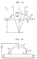
- the microlens 10 includes a small droplet 12 of a transparent liquid, such as water, typically (but not necessarily) with a diameter from several micrometers to several millimeters.
- the droplet 12 is disposed on a transparent substrate 14.
- the substrate is typically hydrophobic or includes a hydrophobic coating.
- the liquid and substrate need only be transparent to light waves having a wavelength within a selected range. Light waves are illustrated by reference numeral 16. Light waves pass through liquid microlens 10 and focus at a focal point or focal spot (designated by reference numeral 18) in a focal plane that is a focal distance "f" from the contact plane between droplet 12 and substrate 14.
- the contact angle " ⁇ " between the droplet 12 and the substrate 14 is determined by interfacial surface tensions (also called interfacial energy) " ⁇ ", generally measured in milli-Newtons per meter (mN/m).
- ⁇ S-V is the interfacial tension between the substrate and the air, gas or other liquid that surrounds the substrate 14
- ⁇ L-V is the interfacial tension between the droplet 12 and the air, gas or other liquid that surrounds the droplet 12
- ⁇ S-L is the interfacial tension between the substrate 14 and the droplet 12.
- the focal length in meters is a function of the radius R and the refractive indices "n", where n Liquid is the refractive index of the droplet 12 and n Vapor is the refractive index of the air, gas or other liquid that surrounds the droplet 12.
- Equation ( 3 ) f R n Liquid ⁇ n Vapor
- the refractive index of the substrate is not important because of the parallel entry and exit planes for the light waves.
- FIG. 1B demonstrates that the phenomena of electrowetting may be used to reversibly change the contact angle ⁇ between a droplet 22 of a conducting liquid (which may or may not be transparent) and a dielectric insulating layer 24 having a thickness designated as "d" and a dielectric constant ⁇ r .
- An electrode, such as metal electrode 26, is positioned below the dielectric layer 24 and is insulated from the droplet 22 by layer 24.
- the droplet 22 may be, for example, a water droplet, and the substrate 24 may be, for example, a Teflon/Parylene surface.
- the droplet 22 When no voltage difference is present between the droplet 22 and the electrode 26, the droplet 22 maintains a shape defined by the volume of the droplet 22 and contact angle ⁇ 1 , where ⁇ 1 is determined by the interfacial tensions ⁇ as explained above.
- the dashed line 28 illustrates that the droplet 22 spreads equally across layer 24 from its central position relative to electrode 26 when a voltage is applied between electrode 26 and droplet 22.
- the voltage may range from several volts to several hundred volts.
- the contact angle ⁇ decreases from ⁇ 1 to ⁇ 2 when the voltage is applied, regardless of polarity, between electrode 26 and the droplet 22.
- the amount of spreading i.e., as determined by the difference between ⁇ 1 and ⁇ 2 , is a function of the applied voltage V.
- ⁇ L-V is the droplet interfacial tension described above
- ⁇ r is the dielectric constant of the insulating layer
- ⁇ 0 is 8.85 ⁇ 10 -12 F/m - the permittivity of a vacuum.
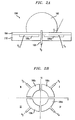
- FIGS. 2A and 2B illustrate a tunable liquid microlens that is capable of varying both position and focal length as described hereafter.
- a tunable liquid microlens 100 includes a droplet 102 of a transparent, conductive liquid disposed on a first surface of a transparent, dielectric insulating layer 104.
- the insulating layer 104 may be, for example, a polyimide coated with a fluorinated polymer, such as a highly fluorinated hydrocarbon.
- the insulating layer 104 should provide predetermined values of contact angle and contact angle hysteresis and have a high dielectric breakdown strength that is appropriate for the applied voltages.
- the microlens 100 includes a plurality of electrodes 106a-106d insulated from the droplet 102 by insulating layer 104.
- the microlens 100 may also include a transparent supporting substrate 110 which supports the electrodes 106 and insulating layer 104.
- the electrodes 106 and the supporting substrate 110 may be, for example, gold and glass, respectively.
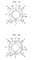
- FIG. 2B is a top plan view of an exemplary configuration for the electrodes 106a-106d. Although one configuration of four electrodes 106a-106d is shown, other numbers, combinations and patterns of electrodes 106 may be utilized depending upon the desired level of control over the tuning of the microlens 100. Each electrode 106a-106d is coupled to a respective voltage V 1 -V 4 and droplet 102, which is centered initially relative to the electrodes 106, is coupled to a droplet electrode 108, which is coupled to a voltage Vo.
- FIG. 2C illustrates this initial position of droplet 102 with a dashed line.
- the position of droplet 102 and the focal length of the microlens 100 can be adjusted by selectively applying a voltage potential between the droplet 102 and the electrodes 106.
- the droplet 102 spreads equally within quadrants I, II, III, and IV (i.e., equally along lateral axes X and Y) as shown by the dashed line of FIG. 2D.
- the contact angle ⁇ between the droplet 102 and insulating layer 104 decreases.
- the electrodes 106 can be selectively biased relative to the droplet electrode (and thus droplet 102) in any number of combinations in order to adjust the contact angle ⁇ and thereby to modify the focal length of the microlens 100.
- the electrodes 106 can be selectively biased in any number of combinations to reposition the droplet 102 relative to an initial location on the insulating layer 104, whereby the lateral position of the focal spot of the microlens is adjusted.
- the microlens allows for the adjustment of the focal spot in three dimensions - the position of the focal spot as determined by the focal length and the lateral position of the focal spot in the focal plane that is parallel with the first surface of the microlens and is a focal length away from the microlens.
- FIG. 3A illustrates one manner of coupling the droplet 102 to a voltage Vo, such as ground or other constant voltage level.
- Microlens 100a may include a supporting substrate 110a which includes a conductive glass, such as indium tin oxide glass. The conductive glass is coupled to voltage Vo and an electrode 116 couples the substrate 110a to the droplet 102. The electrode 116 and supporting substrate 110a may collectively be considered a droplet electrode.
- FIG. 3A also illustrates that the insulating dielectric layer 104 may include a dielectric layer 114 and a hydrophobic coating layer 112. The coating layer 112 should provide a relatively high contact angle ⁇ .
- insulating layer 104a includes a coating layer 112 that is a Teflon film disposed on a polyimide dielectric layer 114.
- droplet electrode 116 may be, for example, a gold electrode evaporated or otherwise deposited on a first surface of an insulating layer 104 (not shown) in an area or plurality of areas that ensures that the electrode 116 maintains contact with the droplet 102 when the droplet 102 changes position along the first surface of the insulating layer 104.
- the electrode 116 is disposed to maintain contact with the droplet 102 when the droplet 102 changes position, the droplet 102 is substantially disposed on the first surface of insulating layer 104.
- the microlens 100B may include a supporting substrate 110a that need not be conductive and may be, for example, non-conductive glass that serves as a mechanical support layer for insulating layer 104 and the electrodes 106. In that case, droplet electrode 116 may be coupled directly to a voltage Vo. Alternatively, the supporting layer 110a may be a conductive glass substrate that is coupled to a voltage Vo. In that embodiment, the droplet electrode 116 may be coupled to the supporting layer 110a. Also shown in FIG. 3B are electrodes 106a-106d and their respective power leads 118a-118d, which are coupled to voltages V 1 -V 4 , respectively. Although an insulating layer 104 is not shown in FIG. 3B, this is for illustrative purposes only, and an insulating layer 104 insulates the droplet 102 and electrode 116 from electrodes 106a-106d.
- FIG. 3C illustrates an exemplary embodiment of a tunable liquid microlens 100C where no electrode 116 is required, thereby reducing any potential interference with the microlens from electrode 116.
- Microlens 100C includes droplet 102 disposed on a first surface of an insulating layer 104b.
- Microlens 100C also includes a transparent conductive supporting layer 110a which serves as a droplet electrode disposed along a second surface of insulating layer 104b opposite the first surface of insulating layer 104b.
- Microlens 100C is shown in cross-section to illustrate that insulating layer 104b includes an aperture 118 defined by the insulating layer 104b and continuing there through.
- the droplet 102 occupies at least a part of the aperture 118, thereby placing the droplet 102 in electrical communication with the droplet electrode, i.e., supporting substrate 110a.
- the supporting substrate 110a is then coupled to a voltage Vo.
- the insulating layer 104b also does not have to be transparent as long as the aperture is wide enough so that the light that penetrates through the aperture is sufficient for the particular application.
- the liquid droplet may be any liquid which is transparent to the desired wavelength and which is intrinsically conductive or which can be made conductive, such as through the use of various additive. Typical examples includes aqueous solutions of various salts.
- the electrodes may be any solid conductive materials, which may or may not be transparent, such as gold, aluminum, or indium tin oxide glass.
- the insulating layer may be any solid dielectric or a set of solid dielectrics that provide high enough dielectric strength and predefined values of contact angle and contact angle hysteresis. The insulating layer may or may not be transparent. Examples include solid polymers, such as polyimide and parylene.
- the supporting substrate may be any substrate that is transparent to a given wavelength, such as glass or a solid polymer.
- the applied voltages depend upon the selected materials, the layout of the microlens, and the desired change in the contact angle, as guided by the above equations (1)-(4). Typical voltages may vary between 0 volts and approximately 200 volts, although the acceptable voltages are not limited to this range.
- the liquid droplet of the microlens may be substantially encompassed by a liquid that is immiscible with the droplet.
- the surrounding liquid may help to prevent the microlens droplet from evaporating.
- various oils or high molecular weight alcohols e.g., pentanol, octanol, etc. may be used.
- the microlens 100C of FIG. 3C was tested.
- the microlens included a droplet 102 including 20 ⁇ l of 0.01 aqueous KNO 3 solution.
- the insulating layer 104b included a 3 ⁇ m thick polyimide layer coated with a very thin ( ⁇ 0.02 to 2 ⁇ m) layer of a highly fluorinated polymer that provided an initial contact angle of approximately 109°.
- a set of four gold electrodes 106 were arranged as shown in FIGS. 2B and 3C.
- the microlens included an ITO (indium tin oxide) glass plate as a conductive transparent supporting substrate 110a shown in FIG. 3C. Operating voltages between 0V and approximately 150V were applied.
- the described microlens may be designed to have a desired contact angle ⁇ when there is no voltage difference between the droplet and the electrodes 106 and a desired contact angle hysteresis. This may be achieved by selecting appropriate materials, dimensions, and volumes as guided by the equations set forth above.
- the microlens therefore allows substantial freedom in both droplet curvature and position control, thereby leading to a wide range of tunability in the microlens, focal length, focal spot position, and numerical aperture.
- the microlens of the present invention may be utilized in several optoelectronic applications.
- the microlens may be used to achieve optimal coupling between an optical signal transmitter 204, such as a laser, and an optical signal receiver 202, such as a photodetector. This is illustrated in FIG. 4. It should be understood from FIG. 4 that the optical signal from transmitter 204 is diverging and will be focused behind the focal plane 206.
- the lens focal distance and lateral positioning of the focal spot 208 within focal plane 206 of the microlens 100 may be adjusted as described above by selectively biasing the plurality of electrodes 106 to achieve this optimal coupling.
- the biasing electrodes can be selectively biased until the highest power is detected at receiver 202 - representing the optimal coupling between transmitter 204 and receiver 202.
- optoelectronic packages i.e., physical apparatuses incorporating optoelectronic components such as lasers and/ or photodetectors, are calibrated by physically moving component parts to achieve optimal coupling. This process can be slow and quite expensive.
- the need to physically align component parts to achieve optimal coupling is eliminated. Rather, the focal length and lateral position of the focal spot of the microlens of the present invention may be adjusted to redirect an optical signal from a transmitter to a fixed receiver.
- a microlens 100 is utilized to couple an optoelectronic component, such as a photodetector 506 that is surface-mounted through a ball grid array 512 on a printed circuit board 500, with an embedded planar waveguide 504.
- an optoelectronic component such as a photodetector 506 that is surface-mounted through a ball grid array 512 on a printed circuit board 500
- Light propagates through a core 502 of planar waveguide 504 as indicated by the directional arrows. The light is reflected by a mirror edge 508 toward a top surface 510 of the printed circuit board 500.
- a tunable liquid microlens 100 is disposed on the top surface 510 of the printed circuit board 500 and directs the light 502 toward photodetector 506 in the direction shown.
- the electrodes of the tunable liquid microlens 100 may be selectively biased to adjust the focal length and lateral focal spot position of the microlens 100 in order to tune the microlens 100 to optimize the transmission of the light from the planar waveguide 504 to the photodetector 506.
- the shape of the microlens is maintained by the application of the appropriate voltage.
- FIGS. 6 and 7 illustrate another exemplary embodiment of a tunable liquid microlens that is capable of varying both focal spot position and focal length, while increasing the range of materials that may be utilized in a tunable liquid microlens.
- the contact angle ⁇ between layer 24 and the droplet 22 may be changed by applying a voltage between the electrode 26 and the droplet 22.
- a stick-slip phenomenon can cause the contact angle ⁇ to change under the applied voltage incrementally, rather than in a smooth transition from the initial contact angle to the final contact angle.
- the droplet While a voltage is applied, the droplet can "stick" to the surface of the substrate 24 and maintain a first contact angle ⁇ X for a period of time. Eventually, under the applied voltage, the droplet “slips" to define a new contact angle ⁇ Y . These incremental jumps can occur several times during a transition between an initial contact angle and a final contact angle, depending upon the applied voltage. Because the droplet initially sticks and then slips, the contact angle ⁇ changes incrementally and no contact angles can easily be achieved that fall between, for example, ⁇ X and ⁇ Y .
- the stick-slip phenomenon is mainly caused by inhomogenaities, impurities or contaminants in the substrate 24, leading to localized inconsistencies in interfacial tensions between the droplet 22 and the substrate 24.
- the stick-slip phenomenon can limit the ability to accurately tune a microlens utilizing electrowetting.
- the other phenomenon closely related to the stick-slip phenomenon is a contact angle hysteresis phenomenon.
- Contact angle hysteresis refers to the difference between the contact angle of the advancing droplet (such as the angle obtained at a given voltage Vo during the voltage increase from, for example, 0V to Vo) and the retracting droplet (such as the contact angle obtained at the same voltage Vo but during the voltage decrease from, for example, Vo to 0V).
- Contact angle hysteresis leads to the dependence of the droplet contact angle on the droplet history - that is whether the voltage was decreasing or increasing - and complicates the droplet control through electrowetting.
- the hysteresis can prevent the droplet from returning to its original shape when the voltage is removed.
- the stick-slip and contact angle hysteresis are closely related phenomena, they are not identical. In particular, it is possible to obtain in certain situations the contact angle hysteresis behavior that is not associated with any appreciable stick-slip behavior.
- any appreciable contact angle hysteresis and stick-slip may be avoided by selecting an appropriate insulating layer that includes, for example, a fluorinated polymer, such as a highly fluorinated hydrocarbon.
- a fluorinated polymer such as a highly fluorinated hydrocarbon.
- a tunable liquid microlens 600 is illustrated.
- the tunable liquid microlens 600 has the same basic structure as the microlens 100 of FIG. 2A and like components share the same reference numerals.
- Tunable liquid microlens 600 includes a relatively thin lubricating layer 800 (illustrated in cross-hatch) disposed on a first surface of insulating layer 104.
- the lubricating layer 800 is spread across the first surface of the insulating layer 104 and droplet 102 is disposed on the lubricating layer 800 such that the lubricating layer 800 is between insulating layer 104 and droplet 102.
- An angle ⁇ a is generally defined between the droplet 102 and a plane 602 that is parallel with the first surface of the insulating layer 104. Like contact angle ⁇ described in connection with FIGS. 2A-3C, angle ⁇ a can be made to change by selectively applying a voltage between electrodes 106 and droplet 102. In this manner, the focal length of the microlens 600 is tunable.
- the lubricating layer separates the droplet 102 from the insulating layer 104 and provides spatially uniform interfacial tension between the droplet 102 and the lubricating layer 800.
- a wider range of materials may be selected for insulating layer 104 because the droplet 102 does not contact any localized inhomogenaities or contaminants that would otherwise lead to contact angle hysteresis and the stick-slip effect between a droplet 102 and an insulating layer 104.
- the microlens can also vary its position relative to insulating layer 104, i.e., along plane 602, by selectively biasing electrodes 106. In this manner, the focal spot position of the tunable liquid microlens 600 may be varied.
- FIG. 6 illustrates that the insulating layer 800 may be implemented as a liquid layer that separates the liquid droplet 102 from the insulating layer 104 when droplet 102 is disposed on lubricating layer 800.
- the microlens 700 includes a surrounding liquid 802 (shown in cross-hatch) that includes lubricating layer 800, that is immiscible with droplet 102, and that substantially surrounds the surface of the droplet 102.
- An angle ⁇ b is defined between the droplet 102 of microlens 700 and a plane 604 that is parallel with the first surface of the insulating layer 104.
- the angle ⁇ b may be varied by selectively biasing electrodes 106 relative to the droplet 102 in order to vary the focal length of the microlens 700.
- the droplet 102 may be repositioned relative to the insulating layer 104, i.e., along plane 604, to change the focal spot position of the microlens 700.
- a lubricating layer 800 can either be spread along the first surface of insulating substrate 104 or the microlens droplet 102 can be completely immersed in a liquid 802 that includes the lubricating layer 800.
- the lubricating layer 800 should be transparent to a desired wavelength of light, although this need not be the case if a structure with an aperture 118 shown in FIG. 3C is utilized. In this case the lubricating layer does not occupy the aperture 118 if the surface energy of the material selected for the supporting conductive layer exceeds a certain threshold value. This happens because the lubricant can wet (i.e., provide zero contact angle) only the surfaces with a surface energy below a certain threshold as further explained below.
- the lubricating layer should be dielectric and should be selected in such as way that it wets the dielectric substrate 104 underneath the microlens droplet 102.
- An exemplary lubricating layer 800 includes a low surface energy liquid that is immiscible with droplet 102.
- One exemplary liquid is a silicone oil.
- fluorinated organic liquids may be used as well, such as fluorosilicones such as FMS-131, FMS-221 (poly(3,3,3-trifluoropropylmethylsiloxane)) and SIB1816.0 [Bis(tridecafluorooctyl)tetramethylsiloxane] available from Gelest, Inc of Tullytown, Pennsylvania.
- the wetting of the substrate by the lubricating layer can either be complete or with a finite, but small, contact angle between the lubricating layer and the insulating substrate 104.
- the lubricating layer 800 naturally forms a thin layer underneath the microlens droplet 102 and substantially prevents contact angle hysteresis and "stick-slip" behavior.
- Both the microlense 600 of FIG. 6 and the microlens 700 of FIG. 7 show a lubricating layer 800 separating the droplet 102 from the insulating layer 104.
- materials having appropriate surface energies ⁇ must be selected. Of course, these materials may be selected somewhat by trial and error, but the following principles may also be utilized.
- a droplet 102 is in a spherical shape, as shown in FIG. 7, when no voltage is applied between the droplet 102 and the electrodes 106, i.e., the surface of the droplet 102 is completely surrounded by a fluid 802 and the droplet 102 forms an angle of 180° with a plane 604 that is parallel with the first surface of the insulating layer 104.
- the angle ⁇ b when no voltage is applied is initially determined by the interfacial tension between the substrate 104 and the droplet 102 ( ⁇ S-L ), the interfacial tension between the substrate 104 and the lubricating liquid 800 ( ⁇ S-F ), and the interfacial tension between the droplet 102 and the lubricating fluid 802 ( ⁇ L-F ).
- ⁇ ij ⁇ i + ⁇ j ⁇ 2 ⁇ i j ⁇ i ⁇ j , where ⁇ ij is a dimensionless interaction parameter that can be computed from the molecular properties of the materials involved, and is close to unity for organic systems.
- ⁇ S-L represents the interfacial surface tension or interfacial energy between the substrate 104 and the droplet 102.
- the surface energy of the substrate 104 is represented as ⁇ S .
- This notation refers to the interfacial surface energy between the material in question (such as substrate 104 in this case) and its saturated vapor.
- Equation ( 7 ) Equation ( 7 ) ⁇ S ⁇ F ⁇ ⁇ S ⁇ L ⁇ L ⁇ F ⁇ ⁇ 1 , or ⁇ S ⁇ F ⁇ ⁇ S ⁇ L ⁇ ⁇ L ⁇ F . This concept is best illustrated in FIG.
- FIG. 8 which is a plot of angle ⁇ b against ⁇ S of the insulating layer for two different ⁇ F 's - 20mN/m and 16 mN/m, corresponding to lubricating fluids including DMS-T11 silicone oil and DMS-T00 silicone oil, respectively, both manufactured by Gelest, Inc. of Tullytown, Pennsylvania.
- the plot of FIG. 8 may be generated utilizing equations (5) and (6).
- the droplet 102 is assumed to be water, with a ⁇ L of 72 mN/m. From the plot of FIG.
- a lubricating layer 800 allows for greater latitude in materials selection since no highly uniform, ultra-clean, low-energy surface is required.
- a lubricant with a ⁇ F of 20 mN/m is employed, a wide range of materials would satisfy the condition that the surface energy ⁇ S be less than approximately 36 mN/m, including such common polymers as polypropylene, polyethylene, polystyrene, etc.
- the tunable liquid microlenses 600, 700 are shown having the basic structure shown in FIG. 2A, other microlens structures, such as those shown and described in connection with FIGS. 3A-3C, are equally appropriate. Likewise, the tunable liquid microlenses 600, 700 may be used in varied optoelectronic applications, such as those described in connection with FIG. 4 and FIG. 5.
- the tunable liquid microlenses 600, 700 allows for both lens position adjustment and focal length tuning. In addition, the tunable liquid microlenses 600, 700 provide still greater freedom in material selection while providing excellent tunability by avoiding the contact angle hysteresis and stick-slip phenomena.
Landscapes
- Physics & Mathematics (AREA)
- General Physics & Mathematics (AREA)
- Optics & Photonics (AREA)
- Mechanical Light Control Or Optical Switches (AREA)
- Transforming Light Signals Into Electric Signals (AREA)
- Electrochromic Elements, Electrophoresis, Or Variable Reflection Or Absorption Elements (AREA)
Applications Claiming Priority (2)
| Application Number | Priority Date | Filing Date | Title |
|---|---|---|---|
| US951637 | 2001-09-13 | ||
| US09/951,637 US6545815B2 (en) | 2001-09-13 | 2001-09-13 | Tunable liquid microlens with lubrication assisted electrowetting |
Publications (2)
| Publication Number | Publication Date |
|---|---|
| EP1293807A1 EP1293807A1 (en) | 2003-03-19 |
| EP1293807B1 true EP1293807B1 (en) | 2006-10-04 |
Family
ID=25491954
Family Applications (1)
| Application Number | Title | Priority Date | Filing Date |
|---|---|---|---|
| EP02252089A Expired - Lifetime EP1293807B1 (en) | 2001-09-13 | 2002-03-22 | Tunable liquid microlens with lubrication assisted electrowetting |
Country Status (6)
| Country | Link |
|---|---|
| US (1) | US6545815B2 (enExample) |
| EP (1) | EP1293807B1 (enExample) |
| JP (1) | JP4414641B2 (enExample) |
| CN (1) | CN1265213C (enExample) |
| CA (1) | CA2395766C (enExample) |
| DE (1) | DE60215093T2 (enExample) |
Families Citing this family (141)
| Publication number | Priority date | Publication date | Assignee | Title |
|---|---|---|---|---|
| US20050002113A1 (en) * | 1997-10-08 | 2005-01-06 | Varioptic | Drop centering device |
| FR2791439B1 (fr) * | 1999-03-26 | 2002-01-25 | Univ Joseph Fourier | Dispositif de centrage d'une goutte |
| US6965480B2 (en) * | 2001-06-19 | 2005-11-15 | Lucent Technologies Inc. | Method and apparatus for calibrating a tunable microlens |
| US7087830B2 (en) * | 2001-08-07 | 2006-08-08 | Justin A. Kent | System for converting turntable motion to MIDI data |
| US7110646B2 (en) * | 2002-03-08 | 2006-09-19 | Lucent Technologies Inc. | Tunable microfluidic optical fiber devices and systems |
| US6936196B2 (en) * | 2002-03-12 | 2005-08-30 | Lucent Technologies Inc. | Solidifiable tunable liquid microlens |
| US6829415B2 (en) * | 2002-08-30 | 2004-12-07 | Lucent Technologies Inc. | Optical waveguide devices with electro-wetting actuation |
| US6911132B2 (en) | 2002-09-24 | 2005-06-28 | Duke University | Apparatus for manipulating droplets by electrowetting-based techniques |
| US7329545B2 (en) * | 2002-09-24 | 2008-02-12 | Duke University | Methods for sampling a liquid flow |
| US20040151828A1 (en) * | 2003-02-04 | 2004-08-05 | Anis Zribi | Method for fabrication and alignment of micro and nanoscale optics using surface tension gradients |
| US6891682B2 (en) * | 2003-03-03 | 2005-05-10 | Lucent Technologies Inc. | Lenses with tunable liquid optical elements |
| US20040191127A1 (en) * | 2003-03-31 | 2004-09-30 | Avinoam Kornblit | Method and apparatus for controlling the movement of a liquid on a nanostructured or microstructured surface |
| WO2004099844A1 (en) * | 2003-05-06 | 2004-11-18 | Koninklijke Philips Electronics N.V. | Electrowetting module |
| KR20050123181A (ko) * | 2003-05-09 | 2005-12-29 | 코닌클리즈케 필립스 일렉트로닉스 엔.브이. | 가변 초점 렌즈 집합체 제조 방법, 전기적 절연 몸체, 가변초점 렌즈, 렌즈 어셈블리, 카메라, 핸드핼드형 장치 및광학 스캔 장치 |
| CN100480774C (zh) * | 2003-05-14 | 2009-04-22 | 皇家飞利浦电子股份有限公司 | 提供可变折射表面的光学像差校正元件及其制造方法 |
| JP4155099B2 (ja) * | 2003-05-16 | 2008-09-24 | セイコーエプソン株式会社 | マイクロレンズの製造方法 |
| JP3800199B2 (ja) * | 2003-05-16 | 2006-07-26 | セイコーエプソン株式会社 | マイクロレンズの製造方法 |
| DE60308161T2 (de) * | 2003-06-27 | 2007-08-09 | Asml Netherlands B.V. | Lithographischer Apparat und Verfahren zur Herstellung eines Artikels |
| US7106519B2 (en) * | 2003-07-31 | 2006-09-12 | Lucent Technologies Inc. | Tunable micro-lens arrays |
| US6847493B1 (en) * | 2003-08-08 | 2005-01-25 | Lucent Technologies Inc. | Optical beamsplitter with electro-wetting actuation |
| US8072688B2 (en) * | 2003-09-24 | 2011-12-06 | Alcatel Lucent | Method for calibrating a photo-tunable microlens |
| JP4628755B2 (ja) * | 2003-11-25 | 2011-02-09 | パナソニック株式会社 | 移動機構及びそれを用いた小型カメラ、ゴニオメーターとファイバースコープ |
| JP4237610B2 (ja) * | 2003-12-19 | 2009-03-11 | 株式会社東芝 | 保守支援方法及びプログラム |
| JP4995712B2 (ja) * | 2004-03-04 | 2012-08-08 | コーニンクレッカ フィリップス エレクトロニクス エヌ ヴィ | 光線に光学収差をもたせる光学部品 |
| US7201318B2 (en) * | 2004-03-11 | 2007-04-10 | Symbol Technologies, Inc. | Optical adjustment for increased working range and performance in electro-optical readers |
| US7048889B2 (en) * | 2004-03-23 | 2006-05-23 | Lucent Technologies Inc. | Dynamically controllable biological/chemical detectors having nanostructured surfaces |
| GB0407236D0 (en) * | 2004-03-30 | 2004-05-05 | Koninkl Philips Electronics Nv | Controllable optical lens |
| JP4595369B2 (ja) * | 2004-03-31 | 2010-12-08 | ブラザー工業株式会社 | 液体移送ヘッド及びこれを備えた液体移送装置 |
| US8139104B2 (en) * | 2004-04-13 | 2012-03-20 | Koninklijke Philips Electronics N.V. | Autostereoscopic display device |
| CA2567550A1 (en) | 2004-05-21 | 2005-12-01 | University Of Cincinnati | Liquid logic structures for electronic device applications |
| KR100541820B1 (ko) * | 2004-05-28 | 2006-01-11 | 삼성전자주식회사 | 반도체 소자 제조를 위한 파티클 검출장치 |
| JP4182927B2 (ja) * | 2004-06-30 | 2008-11-19 | ブラザー工業株式会社 | プリント装置 |
| JP4897680B2 (ja) * | 2004-07-20 | 2012-03-14 | エージェンシー フォー サイエンス, テクノロジー アンド リサーチ | 可変焦点マイクロレンズ |
| JP4539213B2 (ja) * | 2004-07-27 | 2010-09-08 | ブラザー工業株式会社 | 液体移送装置 |
| US7927783B2 (en) * | 2004-08-18 | 2011-04-19 | Alcatel-Lucent Usa Inc. | Tunable lithography with a refractive mask |
| US20060102477A1 (en) | 2004-08-26 | 2006-05-18 | Applera Corporation | Electrowetting dispensing devices and related methods |
| JP2006065045A (ja) | 2004-08-27 | 2006-03-09 | Fuji Photo Film Co Ltd | 光学素子、レンズユニット、および撮像装置 |
| US7507433B2 (en) * | 2004-09-03 | 2009-03-24 | Boston Scientific Scimed, Inc. | Method of coating a medical device using an electrowetting process |
| FR2877734B1 (fr) * | 2004-11-08 | 2007-06-01 | Eastman Kodak Co | Lentille a focale et a symetrie variable |
| US7413306B2 (en) * | 2004-11-18 | 2008-08-19 | Amo Manufacturing Usa, Llc | Sphero cylindrical eye refraction system using fluid focus electrostatically variable lenses |
| US7119035B2 (en) * | 2004-11-22 | 2006-10-10 | Taiwan Semiconductor Manufacturing Company, Ltd. | Method using specific contact angle for immersion lithography |
| US7132614B2 (en) * | 2004-11-24 | 2006-11-07 | Agilent Technologies, Inc. | Liquid metal switch employing electrowetting for actuation and architectures for implementing same |
| EP1835213B1 (en) * | 2004-12-17 | 2012-03-07 | Brother Kogyo Kabushiki Kaisha | Valve and actuator employing capillary electrowetting phenomenon |
| US7030328B1 (en) * | 2004-12-22 | 2006-04-18 | Agilent Technologies, Inc. | Liquid metal switch employing micro-electromechanical system (MEMS) structures for actuation |
| KR101198038B1 (ko) | 2005-01-28 | 2012-11-06 | 듀크 유니버서티 | 인쇄 회로 기판 위의 액적 조작을 위한 기구 및 방법 |
| JP4559274B2 (ja) * | 2005-03-30 | 2010-10-06 | シャープ株式会社 | 画像表示装置 |
| JP2006285031A (ja) * | 2005-04-01 | 2006-10-19 | Sony Corp | 可変焦点レンズとこれを用いた光学装置、可変焦点レンズの製造方法 |
| JP2006302367A (ja) * | 2005-04-19 | 2006-11-02 | Ricoh Co Ltd | 光ピックアップ、調整方法及び光情報処理装置 |
| CN100573245C (zh) * | 2005-04-28 | 2009-12-23 | 夏普株式会社 | 液晶显示装置 |
| US7053323B1 (en) * | 2005-05-04 | 2006-05-30 | Agilent Technologies, Inc. | Liquid metal switch employing an electrically isolated control element |
| JP4547301B2 (ja) * | 2005-05-13 | 2010-09-22 | 株式会社日立ハイテクノロジーズ | 液体搬送デバイス及び分析システム |
| JP2008203282A (ja) * | 2005-06-03 | 2008-09-04 | Sharp Corp | 画像表示装置 |
| KR100686018B1 (ko) * | 2005-06-13 | 2007-02-26 | 엘지전자 주식회사 | 광학기기 |
| US8038266B2 (en) | 2005-06-29 | 2011-10-18 | Brother Kogyo Kabushiki Kaisha | Air bubble trapping apparatus, liquid transporting apparatus, and ink-jet recording apparatus |
| EP1738911B1 (en) | 2005-06-30 | 2010-02-24 | Brother Kogyo Kabushiki Kaisha | Liquid discharging apparatus |
| DE602006002568D1 (de) | 2005-07-27 | 2008-10-16 | Brother Ind Ltd | Druckvorrichtung |
| KR100691278B1 (ko) | 2005-08-30 | 2007-03-12 | 삼성전기주식회사 | 마이크로 렌즈 제조 장치 및 마이크로 렌즈 제조 방법 |
| DE602006006510D1 (de) | 2005-08-30 | 2009-06-10 | Brother Ind Ltd | Vorrichtung und Kopf zum Befördern von Flüssigkeit |
| US7666665B2 (en) | 2005-08-31 | 2010-02-23 | Alcatel-Lucent Usa Inc. | Low adsorption surface |
| WO2007033326A2 (en) * | 2005-09-14 | 2007-03-22 | Welch Allyn, Inc. | Medical apparatus comprising and adaptive lens |
| US8287808B2 (en) * | 2005-09-15 | 2012-10-16 | Alcatel Lucent | Surface for reversible wetting-dewetting |
| US20070059213A1 (en) * | 2005-09-15 | 2007-03-15 | Lucent Technologies Inc. | Heat-induced transitions on a structured surface |
| US7412938B2 (en) * | 2005-09-15 | 2008-08-19 | Lucent Technologies Inc. | Structured surfaces with controlled flow resistance |
| US8734003B2 (en) | 2005-09-15 | 2014-05-27 | Alcatel Lucent | Micro-chemical mixing |
| US8721161B2 (en) * | 2005-09-15 | 2014-05-13 | Alcatel Lucent | Fluid oscillations on structured surfaces |
| CN101097264B (zh) * | 2006-06-26 | 2010-10-13 | 叶哲良 | 可调焦距的透镜 |
| FR2890875B1 (fr) * | 2005-09-22 | 2008-02-22 | Commissariat Energie Atomique | Fabrication d'un systeme diphasique liquide/liquide ou gaz en micro-fluidique |
| US8027095B2 (en) * | 2005-10-11 | 2011-09-27 | Hand Held Products, Inc. | Control systems for adaptive lens |
| KR100691372B1 (ko) | 2005-10-19 | 2007-03-12 | 삼성전기주식회사 | 신뢰성이 확보된 전해액을 포함하는 전기 습윤 장치 |
| US7474470B2 (en) | 2005-12-14 | 2009-01-06 | Honeywell International Inc. | Devices and methods for redirecting light |
| US7443597B2 (en) * | 2005-12-27 | 2008-10-28 | Tessera, Inc. | Liquid lens with piezoelectric voltage converter |
| US20070147816A1 (en) * | 2005-12-27 | 2007-06-28 | Tessera, Inc. | Camera modules with liquid optical elements |
| JP4471220B2 (ja) * | 2006-01-18 | 2010-06-02 | トヨタ自動車株式会社 | 流体プリズム |
| US7896487B2 (en) * | 2006-01-19 | 2011-03-01 | Brother Kogyo Kabushiki Kaisha | Printer and transferring body |
| JP4696943B2 (ja) * | 2006-02-03 | 2011-06-08 | ソニー株式会社 | 光学素子 |
| US7382544B2 (en) * | 2006-02-10 | 2008-06-03 | Honeywell International Inc. | Devices and related methods for light distribution |
| JP4760426B2 (ja) * | 2006-02-13 | 2011-08-31 | ソニー株式会社 | 光学素子およびレンズアレイ |
| US7358833B2 (en) * | 2006-03-14 | 2008-04-15 | Lucent Technologies Inc. | Method and apparatus for signal processing using electrowetting |
| US9476856B2 (en) | 2006-04-13 | 2016-10-25 | Advanced Liquid Logic, Inc. | Droplet-based affinity assays |
| US8492168B2 (en) * | 2006-04-18 | 2013-07-23 | Advanced Liquid Logic Inc. | Droplet-based affinity assays |
| US8613889B2 (en) * | 2006-04-13 | 2013-12-24 | Advanced Liquid Logic, Inc. | Droplet-based washing |
| US20140193807A1 (en) | 2006-04-18 | 2014-07-10 | Advanced Liquid Logic, Inc. | Bead manipulation techniques |
| US8637317B2 (en) * | 2006-04-18 | 2014-01-28 | Advanced Liquid Logic, Inc. | Method of washing beads |
| US7816121B2 (en) * | 2006-04-18 | 2010-10-19 | Advanced Liquid Logic, Inc. | Droplet actuation system and method |
| US8980198B2 (en) | 2006-04-18 | 2015-03-17 | Advanced Liquid Logic, Inc. | Filler fluids for droplet operations |
| WO2007123908A2 (en) * | 2006-04-18 | 2007-11-01 | Advanced Liquid Logic, Inc. | Droplet-based multiwell operations |
| US7901947B2 (en) | 2006-04-18 | 2011-03-08 | Advanced Liquid Logic, Inc. | Droplet-based particle sorting |
| US8658111B2 (en) | 2006-04-18 | 2014-02-25 | Advanced Liquid Logic, Inc. | Droplet actuators, modified fluids and methods |
| US8716015B2 (en) | 2006-04-18 | 2014-05-06 | Advanced Liquid Logic, Inc. | Manipulation of cells on a droplet actuator |
| US8470606B2 (en) * | 2006-04-18 | 2013-06-25 | Duke University | Manipulation of beads in droplets and methods for splitting droplets |
| US10078078B2 (en) | 2006-04-18 | 2018-09-18 | Advanced Liquid Logic, Inc. | Bead incubation and washing on a droplet actuator |
| US8809068B2 (en) | 2006-04-18 | 2014-08-19 | Advanced Liquid Logic, Inc. | Manipulation of beads in droplets and methods for manipulating droplets |
| US7851184B2 (en) * | 2006-04-18 | 2010-12-14 | Advanced Liquid Logic, Inc. | Droplet-based nucleic acid amplification method and apparatus |
| US7815871B2 (en) * | 2006-04-18 | 2010-10-19 | Advanced Liquid Logic, Inc. | Droplet microactuator system |
| US7763471B2 (en) * | 2006-04-18 | 2010-07-27 | Advanced Liquid Logic, Inc. | Method of electrowetting droplet operations for protein crystallization |
| US7439014B2 (en) | 2006-04-18 | 2008-10-21 | Advanced Liquid Logic, Inc. | Droplet-based surface modification and washing |
| US8637324B2 (en) | 2006-04-18 | 2014-01-28 | Advanced Liquid Logic, Inc. | Bead incubation and washing on a droplet actuator |
| US7939021B2 (en) * | 2007-05-09 | 2011-05-10 | Advanced Liquid Logic, Inc. | Droplet actuator analyzer with cartridge |
| US7822510B2 (en) * | 2006-05-09 | 2010-10-26 | Advanced Liquid Logic, Inc. | Systems, methods, and products for graphically illustrating and controlling a droplet actuator |
| US8041463B2 (en) * | 2006-05-09 | 2011-10-18 | Advanced Liquid Logic, Inc. | Modular droplet actuator drive |
| US8179216B2 (en) * | 2006-06-06 | 2012-05-15 | University Of Virginia Patent Foundation | Capillary force actuator device and related method of applications |
| DE102006035925B3 (de) * | 2006-07-31 | 2008-02-21 | Albert-Ludwigs-Universität Freiburg | Vorrichtung und Verfahren zur elektrischen Bewegung von Flüssigkeitstropfen |
| US7643217B2 (en) | 2006-08-10 | 2010-01-05 | Panasonic Corporation | Varifocal lens device |
| EP2074444B1 (en) * | 2006-10-11 | 2017-08-30 | poLight AS | Design of compact adjustable lens |
| JP5255565B2 (ja) * | 2006-10-11 | 2013-08-07 | ポライト エイエス | 調整可能なレンズの製造方法 |
| US20080117521A1 (en) * | 2006-11-17 | 2008-05-22 | Lucent Technologies Inc. | Liquid lenses with cycloalkanes |
| US20080123956A1 (en) * | 2006-11-28 | 2008-05-29 | Honeywell International Inc. | Active environment scanning method and device |
| US7586681B2 (en) * | 2006-11-29 | 2009-09-08 | Honeywell International Inc. | Directional display |
| FR2909293B1 (fr) * | 2006-12-05 | 2011-04-22 | Commissariat Energie Atomique | Micro-dispositif de traitement d'echantillons liquides |
| US8027096B2 (en) | 2006-12-15 | 2011-09-27 | Hand Held Products, Inc. | Focus module and components with actuator polymer control |
| US7813047B2 (en) * | 2006-12-15 | 2010-10-12 | Hand Held Products, Inc. | Apparatus and method comprising deformable lens element |
| JP4848961B2 (ja) * | 2007-01-15 | 2011-12-28 | ソニー株式会社 | 光学素子 |
| US7791815B2 (en) * | 2007-03-13 | 2010-09-07 | Varioptic S.A. | Dielectric coatings for electrowetting applications |
| JP2008238577A (ja) * | 2007-03-27 | 2008-10-09 | Brother Ind Ltd | 液体移送装置 |
| US7830686B2 (en) * | 2007-06-05 | 2010-11-09 | Honeywell International Inc. | Isolated high power bi-directional DC-DC converter |
| US8268246B2 (en) | 2007-08-09 | 2012-09-18 | Advanced Liquid Logic Inc | PCB droplet actuator fabrication |
| US7898096B1 (en) | 2007-08-22 | 2011-03-01 | Thomas Nikita Krupenkin | Method and apparatus for energy harvesting using microfluidics |
| US7862183B2 (en) * | 2007-10-16 | 2011-01-04 | Alcatel-Lucent Usa Inc. | Speckle reduction using a tunable liquid lens |
| JP4442682B2 (ja) | 2007-11-27 | 2010-03-31 | ソニー株式会社 | 光学素子 |
| US20090195882A1 (en) * | 2008-02-05 | 2009-08-06 | Bolle Cristian A | Mechanical lenses |
| JP2009251339A (ja) * | 2008-04-08 | 2009-10-29 | Sony Corp | 光学装置、照明装置、及び、カメラ |
| JP5019476B2 (ja) * | 2008-08-29 | 2012-09-05 | 独立行政法人科学技術振興機構 | 液滴制御装置、及び、液滴制御方法 |
| FR2936167A1 (fr) * | 2008-09-23 | 2010-03-26 | Commissariat Energie Atomique | Micro-dispositif d'analyse d'echantillons liquides. |
| WO2010062481A1 (en) | 2008-11-02 | 2010-06-03 | David Chaum | Near to eye display system and appliance |
| CN102272653B (zh) | 2008-12-30 | 2015-06-17 | 得利捷扫描集团有限公司 | 液体透镜图像捕捉装置 |
| JP2010169976A (ja) * | 2009-01-23 | 2010-08-05 | Sony Corp | 空間像表示装置 |
| US20110038625A1 (en) * | 2009-08-13 | 2011-02-17 | Strategic Polymer Sciences, Inc. | Electromechanical polymer actuators |
| KR101675130B1 (ko) * | 2009-09-03 | 2016-11-10 | 삼성전자주식회사 | 액체 렌즈 |
| TWI422858B (zh) * | 2009-09-04 | 2014-01-11 | Wintek Corp | 電濕潤畫素結構 |
| JP5741107B2 (ja) * | 2011-03-22 | 2015-07-01 | セイコーエプソン株式会社 | メンテナンス装置および液体噴射装置 |
| WO2013009927A2 (en) | 2011-07-11 | 2013-01-17 | Advanced Liquid Logic, Inc. | Droplet actuators and techniques for droplet-based assays |
| US20140333998A1 (en) * | 2013-03-12 | 2014-11-13 | Board Of Trustees, Southern Illinois University | Micro-lens for high resolution microscopy |
| DE102013103708A1 (de) * | 2013-04-12 | 2014-10-16 | Reichle & De-Massari Ag | Optische Verbindungsvorrichtung |
| KR101452930B1 (ko) | 2013-11-21 | 2014-10-22 | 서울대학교산학협력단 | 접촉각 측정 장치 및 측정 방법 |
| DE102014104028B4 (de) * | 2014-03-24 | 2016-02-18 | Sick Ag | Optoelektronische Vorrichtung und Verfahren zum Justieren |
| EP3002510A1 (de) | 2014-10-02 | 2016-04-06 | Sick Ag | Beleuchtungseinrichtung |
| EP3002548B1 (de) | 2014-10-02 | 2016-09-14 | Sick Ag | Beleuchtungseinrichtung und Verfahren zum Erzeugen eines Beleuchtungsfeldes |
| JP5825618B1 (ja) * | 2015-02-06 | 2015-12-02 | 秋田県 | 電界撹拌用電極及びこれを用いた電界撹拌方法 |
| WO2019226432A1 (en) * | 2018-05-21 | 2019-11-28 | Corning Incorporated | Liquid lenses and methods of manufacturing liquid lenses |
| CN109049674B (zh) * | 2018-10-18 | 2023-08-01 | 吉林大学 | 一种针对微系统三维立体结构的增材制造装置及方法 |
| KR102608098B1 (ko) * | 2021-03-31 | 2023-11-30 | 재단법인 오송첨단의료산업진흥재단 | 초점 가변형 액체렌즈 및 이의 제조방법 |
Family Cites Families (20)
| Publication number | Priority date | Publication date | Assignee | Title |
|---|---|---|---|---|
| GB1239141A (enExample) | 1969-03-07 | 1971-07-14 | ||
| US4030813A (en) * | 1974-12-20 | 1977-06-21 | Matsushita Electric Industrial Co., Ltd. | Control element having liquid layer attainable to geometrically uneven state in response to electrical signal |
| US4118270A (en) | 1976-02-18 | 1978-10-03 | Harris Corporation | Micro lens formation at optical fiber ends |
| US4137060A (en) | 1977-07-18 | 1979-01-30 | Robert Bosch Gmbh | Method of forming a lens at the end of a light guide |
| US4653847A (en) | 1981-02-23 | 1987-03-31 | Motorola, Inc. | Fiber optics semiconductor package |
| US4338352A (en) | 1981-02-23 | 1982-07-06 | Mcdonnell Douglas Corporation | Process for producing guided wave lens on optical fibers |
| FR2502345B1 (enExample) | 1981-03-17 | 1985-01-04 | Thomson Csf | |
| NL8204961A (nl) | 1982-12-23 | 1984-07-16 | Philips Nv | Monomode optische transmissievezel met een taps eindgedeelte en werkwijze voor het vervaardigen daarvan. |
| FR2548431B1 (fr) | 1983-06-30 | 1985-10-25 | Thomson Csf | Dispositif a commande electrique de deplacement de fluide |
| CA1243105A (en) | 1984-07-09 | 1988-10-11 | Giok D. Khoe | Electro-optical device comprising a laser diode, an input transmission fibre and an output transmission fibre |
| GB8421105D0 (en) | 1984-08-20 | 1984-09-26 | British Telecomm | Microlens |
| US4948214A (en) | 1989-07-10 | 1990-08-14 | Eastman Kodak Company | Step-index light guide and gradient index microlens device for LED imaging |
| US5518863A (en) | 1992-01-31 | 1996-05-21 | Institut National D'optique | Method of changing the optical invariant of multifiber fiber-optic elements |
| DE4310291A1 (de) | 1993-03-30 | 1994-10-06 | Sel Alcatel Ag | Optischer Koppler |
| US5486337A (en) | 1994-02-18 | 1996-01-23 | General Atomics | Device for electrostatic manipulation of droplets |
| US6014259A (en) | 1995-06-07 | 2000-01-11 | Wohlstadter; Jacob N. | Three dimensional imaging system |
| US5659330A (en) | 1996-05-31 | 1997-08-19 | Xerox Corporation | Electrocapillary color display sheet |
| DE19623270C2 (de) | 1996-06-11 | 1998-05-20 | Juergen Rebel | Adaptives optisches Abbildungssystem zur Abbildung eines von einem Laser emittierten Strahlenbündels |
| FR2769375B1 (fr) | 1997-10-08 | 2001-01-19 | Univ Joseph Fourier | Lentille a focale variable |
| US6449081B1 (en) * | 1999-06-16 | 2002-09-10 | Canon Kabushiki Kaisha | Optical element and optical device having it |
-
2001
- 2001-09-13 US US09/951,637 patent/US6545815B2/en not_active Expired - Lifetime
-
2002
- 2002-03-22 DE DE60215093T patent/DE60215093T2/de not_active Expired - Lifetime
- 2002-03-22 EP EP02252089A patent/EP1293807B1/en not_active Expired - Lifetime
- 2002-07-25 CA CA002395766A patent/CA2395766C/en not_active Expired - Fee Related
- 2002-09-10 CN CNB021416753A patent/CN1265213C/zh not_active Expired - Fee Related
- 2002-09-13 JP JP2002267498A patent/JP4414641B2/ja not_active Expired - Fee Related
Also Published As
| Publication number | Publication date |
|---|---|
| DE60215093T2 (de) | 2007-03-08 |
| EP1293807A1 (en) | 2003-03-19 |
| CA2395766A1 (en) | 2003-03-13 |
| CN1407353A (zh) | 2003-04-02 |
| CN1265213C (zh) | 2006-07-19 |
| JP4414641B2 (ja) | 2010-02-10 |
| US6545815B2 (en) | 2003-04-08 |
| DE60215093D1 (de) | 2006-11-16 |
| CA2395766C (en) | 2006-01-31 |
| US20030048541A1 (en) | 2003-03-13 |
| JP2003177219A (ja) | 2003-06-27 |
Similar Documents
| Publication | Publication Date | Title |
|---|---|---|
| EP1293807B1 (en) | Tunable liquid microlens with lubrication assisted electrowetting | |
| EP1271218B1 (en) | Tunable liquid microlens | |
| US7006299B2 (en) | Method and apparatus for calibrating a tunable microlens | |
| US6665127B2 (en) | Method and apparatus for aligning a photo-tunable microlens | |
| US6778328B1 (en) | Tunable field of view liquid microlens | |
| EP1304591A1 (en) | Photo-tunable liquid microlens | |
| Krupenkin et al. | Tunable liquid microlens | |
| US6936196B2 (en) | Solidifiable tunable liquid microlens | |
| US6400855B1 (en) | N × N optical switching array device and system | |
| US4701021A (en) | Optical modulator | |
| US6847493B1 (en) | Optical beamsplitter with electro-wetting actuation | |
| WO2008063442A1 (en) | Liquid lenses with polycyclic alkanes | |
| US7312917B2 (en) | Variable focal length electro-optic lens | |
| WO2006046185A1 (en) | Optical element, optical device, atmosphere provider, optical scanning device, light coupling device, and method of operating interfacial waves | |
| US8072688B2 (en) | Method for calibrating a photo-tunable microlens | |
| US20040151828A1 (en) | Method for fabrication and alignment of micro and nanoscale optics using surface tension gradients | |
| WO2008095923A1 (en) | Electrowetting based optical element and optical imaging device using such | |
| Seo et al. | Adjustable tilt angle of liquid microlens with four coplanar electrodes | |
| CN111999787A (zh) | 一种电润湿驱动液体可调光学棱镜 | |
| US20220382042A1 (en) | Electrostatic actuation for diffractive optical devices |
Legal Events
| Date | Code | Title | Description |
|---|---|---|---|
| PUAI | Public reference made under article 153(3) epc to a published international application that has entered the european phase |
Free format text: ORIGINAL CODE: 0009012 |
|
| 17P | Request for examination filed |
Effective date: 20020412 |
|
| AK | Designated contracting states |
Kind code of ref document: A1 Designated state(s): AT BE CH CY DE DK ES FI FR GB GR IE IT LI LU MC NL PT SE TR |
|
| AX | Request for extension of the european patent |
Extension state: AL LT LV MK RO SI |
|
| 17Q | First examination report despatched |
Effective date: 20030408 |
|
| GRAP | Despatch of communication of intention to grant a patent |
Free format text: ORIGINAL CODE: EPIDOSNIGR1 |
|
| AKX | Designation fees paid |
Designated state(s): DE FR GB |
|
| GRAS | Grant fee paid |
Free format text: ORIGINAL CODE: EPIDOSNIGR3 |
|
| GRAP | Despatch of communication of intention to grant a patent |
Free format text: ORIGINAL CODE: EPIDOSNIGR1 |
|
| GRAA | (expected) grant |
Free format text: ORIGINAL CODE: 0009210 |
|
| AK | Designated contracting states |
Kind code of ref document: B1 Designated state(s): DE FR GB |
|
| REG | Reference to a national code |
Ref country code: GB Ref legal event code: FG4D |
|
| REF | Corresponds to: |
Ref document number: 60215093 Country of ref document: DE Date of ref document: 20061116 Kind code of ref document: P |
|
| ET | Fr: translation filed | ||
| PLBE | No opposition filed within time limit |
Free format text: ORIGINAL CODE: 0009261 |
|
| STAA | Information on the status of an ep patent application or granted ep patent |
Free format text: STATUS: NO OPPOSITION FILED WITHIN TIME LIMIT |
|
| 26N | No opposition filed |
Effective date: 20070705 |
|
| REG | Reference to a national code |
Ref country code: GB Ref legal event code: 732E Free format text: REGISTERED BETWEEN 20131031 AND 20131106 |
|
| REG | Reference to a national code |
Ref country code: FR Ref legal event code: CD Owner name: ALCATEL-LUCENT USA INC. Effective date: 20131122 |
|
| REG | Reference to a national code |
Ref country code: FR Ref legal event code: GC Effective date: 20140410 |
|
| REG | Reference to a national code |
Ref country code: FR Ref legal event code: RG Effective date: 20141015 |
|
| REG | Reference to a national code |
Ref country code: FR Ref legal event code: PLFP Year of fee payment: 14 |
|
| REG | Reference to a national code |
Ref country code: FR Ref legal event code: PLFP Year of fee payment: 15 |
|
| REG | Reference to a national code |
Ref country code: FR Ref legal event code: PLFP Year of fee payment: 16 |
|
| REG | Reference to a national code |
Ref country code: FR Ref legal event code: PLFP Year of fee payment: 17 |
|
| PGFP | Annual fee paid to national office [announced via postgrant information from national office to epo] |
Ref country code: DE Payment date: 20190312 Year of fee payment: 18 Ref country code: GB Payment date: 20190320 Year of fee payment: 18 |
|
| PGFP | Annual fee paid to national office [announced via postgrant information from national office to epo] |
Ref country code: FR Payment date: 20190213 Year of fee payment: 18 |
|
| REG | Reference to a national code |
Ref country code: DE Ref legal event code: R119 Ref document number: 60215093 Country of ref document: DE |
|
| PG25 | Lapsed in a contracting state [announced via postgrant information from national office to epo] |
Ref country code: FR Free format text: LAPSE BECAUSE OF NON-PAYMENT OF DUE FEES Effective date: 20200331 Ref country code: DE Free format text: LAPSE BECAUSE OF NON-PAYMENT OF DUE FEES Effective date: 20201001 |
|
| GBPC | Gb: european patent ceased through non-payment of renewal fee |
Effective date: 20200322 |
|
| PG25 | Lapsed in a contracting state [announced via postgrant information from national office to epo] |
Ref country code: GB Free format text: LAPSE BECAUSE OF NON-PAYMENT OF DUE FEES Effective date: 20200322 |