EP1293607A2 - Elément de revêtement de sol pour former un caniveau de drainage - Google Patents
Elément de revêtement de sol pour former un caniveau de drainage Download PDFInfo
- Publication number
- EP1293607A2 EP1293607A2 EP02020377A EP02020377A EP1293607A2 EP 1293607 A2 EP1293607 A2 EP 1293607A2 EP 02020377 A EP02020377 A EP 02020377A EP 02020377 A EP02020377 A EP 02020377A EP 1293607 A2 EP1293607 A2 EP 1293607A2
- Authority
- EP
- European Patent Office
- Prior art keywords
- floor covering
- covering element
- element according
- face
- channel section
- Prior art date
- Legal status (The legal status is an assumption and is not a legal conclusion. Google has not performed a legal analysis and makes no representation as to the accuracy of the status listed.)
- Withdrawn
Links
Images


Classifications
-
- E—FIXED CONSTRUCTIONS
- E01—CONSTRUCTION OF ROADS, RAILWAYS, OR BRIDGES
- E01C—CONSTRUCTION OF, OR SURFACES FOR, ROADS, SPORTS GROUNDS, OR THE LIKE; MACHINES OR AUXILIARY TOOLS FOR CONSTRUCTION OR REPAIR
- E01C11/00—Details of pavings
- E01C11/22—Gutters; Kerbs ; Surface drainage of streets, roads or like traffic areas
- E01C11/224—Surface drainage of streets
- E01C11/227—Gutters; Channels ; Roof drainage discharge ducts set in sidewalks
- E01C11/229—Shallow gutters, i.e. gutters forming a minor pothole
Definitions
- the invention relates to a flooring element for formation a gutter, with a top on which a gutter section is formed, a bottom, two on opposite Pages arranged in the longitudinal direction of the Channel section extending long sides, a first End face, on which a first cross-section of the mouth of the channel section lies, and one opposite the first end face second face, on the second cross section of the mouth of the channel section, with the End faces in each case at least one in the longitudinal direction of the channel section protruding engagement section and at least a recessed in the longitudinal direction of the channel section Receiving section is formed, each engagement section with one receiving section and each receiving section with an engaging portion of an adjacent one Flooring element can be brought into engagement, wherein one formed between the underside and the first end face Edge has a course that is essentially congruent with a course of one between the bottom and the second end face formed edge and the edges are not parallel to each other.
- gutter stones for example on roadsides or paved paths or Squares are usually prefabricated gutter stones used, each forming a channel section and in be put together in a row, whereby the groove is formed is.
- To ensure mutual security of neighboring positions To reach gutter stones, it is for example from DE 85 09 982 U1 and DE 295 14 127 U1 known, on the one respective mouth cross-section of the channel section end faces each have at least one in the longitudinal direction of the groove portion protruding engagement portion to form and to provide recesses in the engage an engaging portion of an adjacent gutter stone can. This way, between neighboring Gutter stones a mutual engagement in the form of a toothing reached, the relative displacement of the gutter stones prevented transversely to the longitudinal direction of the channel.
- both according to DE 85 09 982 U1 also according to DE 295 14 127 U1 have the end faces of the gutter stone is a complementary shape and thus congruent Courses of their between the bottom and of the respective end face formed.
- the shape of the end faces is symmetrical to a central longitudinal axis of the gutter stone and the end faces run in a basic version of the gutter stone essentially parallel to each other and perpendicular to the longitudinal direction of the Gutter section. This way you can use the gutter stone according to the basic version, however, only linear Reach channels.
- the invention is based on the object; a flooring element of the type mentioned, with which both a rectilinear as well as a curved channel course can be formed is.
- edges K 1.1 and K 2.1 of the floor covering element according to the invention make it possible to place a floor covering element in one of two possible orientations on an already laid floor covering element.
- the edges K 1.1 and K 2.1 have an essentially congruent course, but are not arranged parallel to one another and form a preferably acute angle ⁇ between them. This corresponds to the structure of the curve stones known from the prior art. If the floor covering elements according to the invention are placed against one another in the same orientation, the first end face of one floor covering element engaging with the second end face of the adjacent floor covering element, the course of the floor channel is deflected by the angle ⁇ for each floor covering element.
- each end face of the gutter block according to the invention can optionally be brought into engagement with the first or the second end face of an adjacent gutter block, which is ensured by the point-symmetrical course of the edges K 1.1 and K 2.1 .
- edges K 1.1 and K 2.1 each have a polygonal course, which can preferably be a zigzag course and in particular an S or Z-shaped course. Due to the zigzag shape of the edges K 1.1 and K 2.1 there is a good mutual engagement of adjacent flooring elements and in particular a large mutual contact with a lateral load acting transversely to the longitudinal direction, so that high point stresses are avoided and a high level of fracture resistance is ensured is.
- Both the end faces and the long sides of the floor covering element preferably comprise vertical wall sections which are oriented essentially perpendicular to the underside.
- the floor covering element has a constant outline contour over its entire height and an edge K 1.2 formed between the upper side and the first end face lies in the vertical projection of the edge K 1.1 formed between the underside and the first end face.
- an edge K 2.2 formed between the upper side and the second end face lies in the vertical projection of the edge K 2.1 formed between the underside and the second end face.
- the engagement section should by a sufficient amount in the longitudinal direction of the channel section protrude from the front. It has proven to be advantageous if the extent to which the engaging portion protrudes from the respective end face, about 0.1 to 0.4 times and especially 0.2 times that measured transversely to the longitudinal direction of the channel section Width of the flooring element is.
- the mutual angular offset between the edges K 1.1 and K 2.1 takes place around a point D lying outside the floor covering element.
- the two edges enclose an angle ⁇ between them which is in the range from 2 ° to 10 ° and in particular in the range from 5 ° to 7 ° lies.
- the point D should have a distance of approximately 5 to 25 times and in particular 8 to 12 times the width of the floor covering element measured transversely to the longitudinal direction of the channel section from the center thereof.
- the flooring elements form a substantially rectilinear gutter arranged in an alternating arrangement the outer surface of the gutter should be straight and run in one plane. This will be in continuing education the invention achieved in that the long sides run straight and parallel to each other.
- the course of the channel section within the flooring element can either be straight or slightly curved his.
- an excessive deflection of the Preventing flow is in an embodiment of the invention provided that a longitudinal center line of the gutter section runs curved and especially on a circular arc around a center lying outside the flooring element lies around which the end faces are relative to each other are angularly offset. It can be provided that the
- the distance from the center of the longitudinal center line should be larger by a factor f than the distance of point D from the longitudinal center line be, the factor f in the range of 1.0 to 5.0 and is in particular in the range from 2.0 to 3.0.
- the point D and the center are arranged so that the point D lies between the center and the flooring element.
- the channel section has of the flooring element relative to its longitudinal center line symmetrical cross section that is either continuous be curved concave or polygonal can.
- the lowest point of the flow cross-section of the channel section is called the bottom point.
- the bottom points all successive cross sections of the channel section thus result in a bottom line that is preferred corresponds to the longitudinal center line of the channel section.
- the surface of the Channel section formed with a dummy structure is.
- the flooring element is preferably made of concrete, however, appropriate flooring elements can be used also manufacture from natural stone or artificial stone.
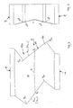
- a flooring element 10 shown in FIGS. 1 to 3 in the form of a monolithic concrete part has a flat, substantially horizontal bottom 16 and a top 11, on which a channel section 20 is formed, the runs in the longitudinal direction L and on a first end face 12 a first cross section of the muzzle and on one of the first end face 12 opposite second end face 13 has a second mouth cross-section.
- the gutter section 20 is arranged from two on opposite sides, extending in the longitudinal direction L of the channel section 20 Long sides 14, 15 limited.
- the first face 12, the second end face 13 and the long sides 14 and 15 each have vertical wall sections that are essentially run perpendicular to the underside 16.
- the channel section 20 has a symmetrical, polygonal concave cross section with an in Longitudinal direction L running longitudinal center line S which the Bottom line of channel section 20, i.e. the the low points of all the channel cross-sections lying one behind the other Line corresponds.
- the long sides 14 and 15 run parallel to one another and each comprise a vertical wall surface.
- the first end face 12 and the second end face 13 have a polygon-like course composed of a plurality of wall sections.
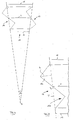
- an edge K 1.1 formed between the underside 16 and the first end face 13 has a course which is essentially congruent with the course of an edge K 2.1 formed between the underside 16 and the second end face 13, wherein however, the edges K 1.1 and K 2.1 do not run parallel to one another, but are angularly offset by an angle ⁇ about a point D outside the floor covering element 10 (see FIG. 4).
- the point D has a distance from the center of the floor covering element of approximately 8 to 12 times the width of the floor covering element measured transversely to the longitudinal direction L of the channel section and the angle ⁇ is preferably in the range from 3 ° to 7 ° and in particular in Range from 5 ° to 7 °, it being pointed out that the dimensions and angles shown in the figures are shown enlarged for the purpose of illustration.
- Both the edge K 1.1 and the edge K 2.1 have an S-shaped course which is also at their center P 1 or P 2 .
- the center point P 1 lies below the longitudinal center line S of the channel section 20.
- the first end face 12 thus related to an imaginary connecting line T between the front ends of the long sides 14 and 15 one protruding in the longitudinal direction L of the channel section, in supervision triangular engagement portion 12a one side of the longitudinal center line S of the gutter section and a complementary receiving portion 12b on the other side of the longitudinal center line S.
- the in Longitudinal direction L of the channel section measured maximum Extension h of the engagement section 12a should at least have 0.1 times the width of the flooring element and points in the embodiment shown in FIG. 5 about 0.2 times the width of the flooring element on.
- a corresponding engagement section 13a and a corresponding receiving section 13b are formed on the second end face 13 opposite the first end face 12, these sections, however, due to the congruent course of the edges K 1.1 and K 2.1 compared to the arrangement on the first end face 12 in an exchanged manner Arranged in this way, that is, on the side of the longitudinal center line S of the channel section 15, on which the first end face 12 has the engagement section 12a, a complementary receiving section 13b is formed on the second end face 13, and on that side of the longitudinal center line S of the channel section 20, on which the first end face 12 has the receiving section 12b, the complementary engagement section 13a is formed on the second end face 13.
- the longitudinal center line runs S of the channel section 20 curved around on a circular arc a center, not shown, of the flooring element 10 is further away than point D, where the point D between the center point and the flooring element lies.
- the outer top point P E1 of the engaging section 12a of the first end face 12 is a small amount relative to the upper, most retracted point P A2 of the receiving section 13b of the second end face 13 with respect to the longitudinal direction L of the channel section 20 laterally offset.
- a corresponding lateral offset also exists between the upper, most retracted point P A1 of the receiving section 12b of the first end face 12 relative to the upper outer tip point P E2 of the engaging section 13a of the second end face 13.
- This offset is due to the angular offset between the edges K 1.1 and K 2.1 due to the angle ⁇ .
- FIG. 3 ' there is also a slight height offset between the points mentioned in order to avoid excessive cracks in the surface of the channel when a channel is built up.
- Fig. 6 shows the construction of a gutter from several flooring elements 10, which are placed in the same orientation are, i.e. a first floor covering element 10 * is present its second face with the first face one adjacent flooring element 10 ** in plant, the Engagement section 12a ** of the first end face of the applied Flooring element 10 ** with a tight fit in the Receiving section 13b * of the second end face of the first Flooring element 10 * engages. Accordingly, the Engagement portion 13a * of the second end face of the first Flooring element 10 * with a tight fit in the receiving section 12b ** the first end face of the created flooring element 10 ** a.
- the result is a curved one Gutter, because each flooring element created around the Angle ⁇ compared to the previous flooring element is twisted.
- the flooring elements are alternating Alignment aligned.
- a first one Floor covering element 10 * becomes a second floor covering element 10 ** created so that the second end face 13 * of the first Floor covering element 10 * with the second end face 13 ** of applied flooring element 10 ** engages.
- the floor covering element shown in supervision in FIG. 8 differs from the aforementioned flooring element essentially in that on the top all over a dummy joint structure 17 is formed that intersects Grooves, which creates the visual impression, as if the flooring element made of a variety of individual stones be composed. All other essentials Features of the flooring element according to FIG. 8 correspond 1 to 5.
- the floor covering element according to FIG. 9 differs from the floor covering element according to FIG. 8 on the one hand in that the false joint structure is not applied in a substantially square or diamond-shaped grid, but in a large rectangular grid with square sections in between.
- the end face each has two engagement sections 12a projecting in the longitudinal direction of the channel section and two receiving sections 12b and 13b complementary thereto.
- the edges K 1.1 and K 2.2 thus have a course in the form of a double Z or a double S.
- Fig. 10 shows a modification of the flooring element according to 1, which differs from this only in that that the flooring element 10 from two individual stone parts 10 'and 10' '.
- the flooring element 10 in the longitudinal direction in the two stone parts 10 'and 10' 'split, thus forming the flooring element 10 are assembled laterally.
- Fig. Figure 10 shows the interface between the two Stone parts 10 'and 10' 'in the longitudinal direction L of the flooring element and has a zigzag or S or Z-shaped course, so that a good mutual engagement of the two stone parts is reached.
- the dividing surface runs in the area of the longitudinal center line S of the channel section serpentine around it, so that a Part of the longitudinal center line S on the one stone part 10 ' and the remaining part of the longitudinal center line S on the other stone part 10 ''.
Applications Claiming Priority (3)
| Application Number | Priority Date | Filing Date | Title |
|---|---|---|---|
| DE20115271U | 2001-09-15 | ||
| DE20115271U DE20115271U1 (de) | 2001-09-15 | 2001-09-15 | Bodenbelagelement zur Bildung einer Bodenrinne |
| CA002403581A CA2403581A1 (fr) | 2001-09-15 | 2002-09-16 | Element de recouvrement formant un caniveau |
Publications (2)
| Publication Number | Publication Date |
|---|---|
| EP1293607A2 true EP1293607A2 (fr) | 2003-03-19 |
| EP1293607A3 EP1293607A3 (fr) | 2004-02-11 |
Family
ID=32928339
Family Applications (1)
| Application Number | Title | Priority Date | Filing Date |
|---|---|---|---|
| EP02020377A Withdrawn EP1293607A3 (fr) | 2001-09-15 | 2002-09-12 | Elément de revêtement de sol pour former un caniveau de drainage |
Country Status (4)
| Country | Link |
|---|---|
| US (1) | US20030070384A1 (fr) |
| EP (1) | EP1293607A3 (fr) |
| CA (1) | CA2403581A1 (fr) |
| DE (1) | DE20115271U1 (fr) |
Cited By (1)
| Publication number | Priority date | Publication date | Assignee | Title |
|---|---|---|---|---|
| EP2431523A3 (fr) * | 2010-09-21 | 2013-01-30 | Lithonplus GmbH & Co. KG | Système de caniveau incliné de manière profilée |
Families Citing this family (5)
| Publication number | Priority date | Publication date | Assignee | Title |
|---|---|---|---|---|
| WO2014078738A1 (fr) * | 2012-11-16 | 2014-05-22 | Keystone Retaining Wall Systems Llc | Surface de raccordement pour une unité structurale |
| US9021761B2 (en) | 2013-03-15 | 2015-05-05 | Keystone Retaining Wall Systems Llc | Building unit with mating sides |
| US9739028B2 (en) | 2013-03-15 | 2017-08-22 | Keystone Retaining Wall Systems Llc | Irregular trapezoidal building unit and wall structure including same |
| CA2936898C (fr) | 2015-07-24 | 2019-03-12 | Keystone Retaining Wall Systems, Llc | Surface de connexion d'une unite structurelle et methode de fabrication associee |
| US9809971B2 (en) * | 2016-02-25 | 2017-11-07 | Spherical Block LLC | Architectural building block |
Citations (2)
| Publication number | Priority date | Publication date | Assignee | Title |
|---|---|---|---|---|
| DE8509982U1 (de) | 1985-04-03 | 1985-05-23 | Gebr. Greiner GmbH,Betonsteinwerk, 7441 Neckartailfingen | Bauplatte, insbesondere für den Straßen- und Wegebau |
| DE29514127U1 (de) | 1995-09-02 | 1995-11-02 | Studio Schroeder & Partner | Rinnenstein |
Family Cites Families (48)
| Publication number | Priority date | Publication date | Assignee | Title |
|---|---|---|---|---|
| US764459A (en) * | 1902-10-31 | 1904-07-05 | Samuel D Hackman | Building-block. |
| US729918A (en) * | 1902-11-26 | 1903-06-02 | Johann L Braun | Brick. |
| US831732A (en) * | 1905-05-11 | 1906-09-25 | Melville C Momsen | Plastic building-block. |
| US1024276A (en) * | 1911-02-01 | 1912-04-23 | Alfred S Nash | Building-block. |
| US1025406A (en) * | 1911-06-05 | 1912-05-07 | William H Koenig | Building-block. |
| US1071330A (en) * | 1912-03-27 | 1913-08-26 | Patrick H Mcdonough | Joint. |
| US1070572A (en) * | 1912-09-10 | 1913-08-19 | Spofford F Wyckoff | Joint for wooden columns, conduits, and the like. |
| US1261426A (en) * | 1915-03-31 | 1918-04-02 | Nat Fire Proofing Company | Tile structure and tile therefor. |
| US1265220A (en) * | 1918-02-21 | 1918-05-07 | William James Lyle | Building construction and block therefor. |
| US1350434A (en) * | 1919-12-12 | 1920-08-24 | Herman J Barsness | Cement section for circular buildings |
| US1425991A (en) * | 1920-12-06 | 1922-08-15 | Earl W Lesher | Shingle |
| US1462605A (en) * | 1922-03-20 | 1923-07-24 | Cocq Frank Le | Cylindrical structure and blocks thereof |
| US1500808A (en) * | 1922-11-10 | 1924-07-08 | Fuhrmann John | Building block |
| US1710833A (en) * | 1927-05-03 | 1929-04-30 | Mirabella Colombo | Concrete brick and method of building therewith |
| US1686757A (en) * | 1927-06-24 | 1928-10-09 | Howard R Loughridge | Building block |
| US1727362A (en) * | 1927-11-07 | 1929-09-10 | Bone Russell Glenn | Three-walled building block |
| US2059664A (en) * | 1934-06-13 | 1936-11-03 | Rivet Grip Steel Co | Fireproof metal-clad insulating plank |
| US2126011A (en) * | 1936-04-16 | 1938-08-09 | Hedinger Fred Henry | Cavity brick for building purposes |
| US2201110A (en) * | 1936-06-16 | 1940-05-14 | Makram Latif Tewfik | Brick or block |
| US2199112A (en) * | 1938-10-27 | 1940-04-30 | Jeremiah J O'leary | Structural block |
| US2305112A (en) * | 1942-06-22 | 1942-12-15 | Paul E Scott | Machine for making precast blocks |
| US2340526A (en) * | 1942-07-10 | 1944-02-01 | Norvin H Green | Paving block |
| US2530940A (en) * | 1947-05-28 | 1950-11-21 | Dahlin John | Wall construction |
| US3355849A (en) * | 1965-07-09 | 1967-12-05 | Hancock Norman Lee | Building wall and tapered interfitting blocks therefor |
| NL6514966A (fr) * | 1965-11-17 | 1967-05-18 | ||
| DE1658496C3 (de) * | 1967-01-19 | 1982-05-27 | Müller & Warnke, 6367 Karben | Verbundpflasterstein |
| US3394521A (en) * | 1967-07-05 | 1968-07-30 | Coleman Myron | Block for refractory linings |
| DE2354600C3 (de) * | 1973-10-31 | 1979-05-23 | Jordan, Reinhard, 7570 Baden-Baden | Mit Durchbrechungen versehener Verbundstein und Verband aus Verbundsteinen |
| US3962842A (en) * | 1975-05-30 | 1976-06-15 | Wilhelm William D | Mortarless interlocking blocks |
| FR2385846A1 (fr) * | 1977-03-29 | 1978-10-27 | Magne Bernard | Elements prefabriques pour allees pietonnieres |
| GB2131062B (en) * | 1981-11-12 | 1985-06-26 | Stratton Frank | Improved building block or panel |
| US4522006A (en) * | 1983-06-13 | 1985-06-11 | Plikuhn Keith A | Drum and drum body formed from adhered, solid blocks of wood |
| BE904200A (fr) * | 1986-02-07 | 1986-05-29 | Hanota Holdings Sa | Bloc de construction et construction realisee au moyen de ce bloc. |
| US4773790A (en) * | 1986-06-04 | 1988-09-27 | Gerhard Hagenah | Groundcovering element, especially (concrete) slab |
| DE8801496U1 (fr) * | 1988-02-06 | 1988-03-17 | Birco Baustoffwerk Gmbh, 7570 Baden-Baden, De | |
| US4925338A (en) * | 1988-11-18 | 1990-05-15 | K-Dron, Inc. | Decorative functional element for construction and the like |
| HU225850B1 (en) * | 1996-04-11 | 2007-10-29 | Karl Kortmann | Concrete block, in particular for paving a petrol station or the like |
| US6226951B1 (en) * | 1996-12-11 | 2001-05-08 | Azar Holdings Ltd. | Concrete building blocks |
| DE29711715U1 (de) * | 1997-07-04 | 1997-11-06 | Fiege & Bertoli Gmbh & Co Kg | Randstein |
| US6053661A (en) * | 1997-11-21 | 2000-04-25 | Polar Industries, Inc. | Variable fitting foam blocks as aggregate |
| DE29800119U1 (de) * | 1998-01-07 | 1998-03-12 | Drott Stefan | Formstein |
| US5984589A (en) * | 1998-03-10 | 1999-11-16 | Ciccarello; Charles | Wall construction block with retaining pin inserts |
| US6082067A (en) * | 1999-02-08 | 2000-07-04 | Allan Block Corporation | Dry stackable block structures |
| EP1088941B1 (fr) * | 1999-10-02 | 2006-06-21 | Kombilith GmbH Entwicklung und Verwertung | Caniveau et élément de caniveau pour celui-ci |
| DE20011841U1 (de) * | 2000-07-03 | 2000-09-28 | Roth Reiner | Betonpalisade |
| US6606835B1 (en) * | 2001-02-02 | 2003-08-19 | Augustin J. Bilka | Blocks and walls constructed therewith |
| US6523317B1 (en) * | 2001-08-31 | 2003-02-25 | Allan Block Corporation | Wall block with interlock |
| CA2359923C (fr) * | 2001-10-25 | 2004-12-14 | Tony Azar | Blocs de construction |
-
2001
- 2001-09-15 DE DE20115271U patent/DE20115271U1/de not_active Expired - Lifetime
-
2002
- 2002-09-12 EP EP02020377A patent/EP1293607A3/fr not_active Withdrawn
- 2002-09-16 CA CA002403581A patent/CA2403581A1/fr not_active Abandoned
- 2002-09-16 US US10/243,936 patent/US20030070384A1/en not_active Abandoned
Patent Citations (2)
| Publication number | Priority date | Publication date | Assignee | Title |
|---|---|---|---|---|
| DE8509982U1 (de) | 1985-04-03 | 1985-05-23 | Gebr. Greiner GmbH,Betonsteinwerk, 7441 Neckartailfingen | Bauplatte, insbesondere für den Straßen- und Wegebau |
| DE29514127U1 (de) | 1995-09-02 | 1995-11-02 | Studio Schroeder & Partner | Rinnenstein |
Cited By (1)
| Publication number | Priority date | Publication date | Assignee | Title |
|---|---|---|---|---|
| EP2431523A3 (fr) * | 2010-09-21 | 2013-01-30 | Lithonplus GmbH & Co. KG | Système de caniveau incliné de manière profilée |
Also Published As
| Publication number | Publication date |
|---|---|
| DE20115271U1 (de) | 2003-02-06 |
| EP1293607A3 (fr) | 2004-02-11 |
| CA2403581A1 (fr) | 2004-03-16 |
| US20030070384A1 (en) | 2003-04-17 |
Similar Documents
| Publication | Publication Date | Title |
|---|---|---|
| EP0648291B1 (fr) | Pave avec elements d'espacement lateraux | |
| EP0424592B1 (fr) | Pierres autobloquantes | |
| EP0377460B1 (fr) | Ensemble de construction constitué par des pavés en béton | |
| WO2001094703A1 (fr) | Pierre artificielle permettant de fixer des surfaces de circulation exterieures | |
| EP0584336A1 (fr) | Lot de paves prets-a-monter. | |
| EP0016353A1 (fr) | Ensemble d'éléments de construction pour ériger des structures tridimensionnelles | |
| DE19520887C2 (de) | Pflastersteinverlegeelement | |
| EP1149207B1 (fr) | Element de palissade | |
| EP1293607A2 (fr) | Elément de revêtement de sol pour former un caniveau de drainage | |
| EP1024226B1 (fr) | Pierre artificielle pour revêtements | |
| DE4131423A1 (de) | Bausatz aus beton-formsteinen sowie eine hieraus erstellte schwergewichts-stuetzmauer | |
| EP1088941A1 (fr) | Caniveau et élément de caniveau pour celui-ci | |
| EP1170433B1 (fr) | Palissade en béton | |
| EP1149218B1 (fr) | Element de palissade | |
| EP1097273B1 (fr) | Mur, en particulier pour la stabilisation sans mortier de buissons, terrasses, talus ou analogues | |
| EP0233603A2 (fr) | Pierre à parer autobloquante | |
| DE4200335C2 (de) | Verbundpflasterstein sowie Verbundpflaster hergestellt unter Verwendung dieses Verbundpflastersteines | |
| EP0954639B1 (fr) | Jeu de construction a briques moulees | |
| DE202017105303U1 (de) | Rasenstegplatte | |
| DE4112819C2 (de) | Pflastersteinsatz, Verbindungsstein sowie unter Verwendung des Pflastersteinsatzes hergestelltes befahrbares Pflaster | |
| DE19509479A1 (de) | Pflasterstein | |
| DE8013431U1 (de) | Formstein für Verbundpflasterung | |
| DE19746295A1 (de) | Plattenförmiger Palisaden/Mauerstein | |
| DE3834267A1 (de) | Pflasterstein zum herstellen von befahrbaren, begruenten flaechen | |
| DE10206158B4 (de) | Bodenbelagelement mit abgewinkelter Grundform und durchgehenden Öffnungen |
Legal Events
| Date | Code | Title | Description |
|---|---|---|---|
| PUAI | Public reference made under article 153(3) epc to a published international application that has entered the european phase |
Free format text: ORIGINAL CODE: 0009012 |
|
| AK | Designated contracting states |
Kind code of ref document: A2 Designated state(s): AT BE BG CH CY CZ DE DK EE ES FI FR GB GR IE IT LI LU MC NL PT SE SK TR Designated state(s): AT BE BG CH CY CZ DE DK EE ES FI FR GB GR IE IT LI LU MC NL PT SE SK TR |
|
| AX | Request for extension of the european patent |
Extension state: AL LT LV MK RO SI |
|
| PUAL | Search report despatched |
Free format text: ORIGINAL CODE: 0009013 |
|
| AK | Designated contracting states |
Kind code of ref document: A3 Designated state(s): AT BE BG CH CY CZ DE DK EE ES FI FR GB GR IE IT LI LU MC NL PT SE SK TR |
|
| AX | Request for extension of the european patent |
Extension state: AL LT LV MK RO SI |
|
| AKX | Designation fees paid | ||
| REG | Reference to a national code |
Ref country code: DE Ref legal event code: 8566 |
|
| STAA | Information on the status of an ep patent application or granted ep patent |
Free format text: STATUS: THE APPLICATION IS DEEMED TO BE WITHDRAWN |
|
| 18D | Application deemed to be withdrawn |
Effective date: 20040812 |