EP1292128A2 - Vorichtung und Verfahren zur Bildaufnahme - Google Patents
Vorichtung und Verfahren zur Bildaufnahme Download PDFInfo
- Publication number
- EP1292128A2 EP1292128A2 EP02256194A EP02256194A EP1292128A2 EP 1292128 A2 EP1292128 A2 EP 1292128A2 EP 02256194 A EP02256194 A EP 02256194A EP 02256194 A EP02256194 A EP 02256194A EP 1292128 A2 EP1292128 A2 EP 1292128A2
- Authority
- EP
- European Patent Office
- Prior art keywords
- image pickup
- data
- image
- correction
- picked
- Prior art date
- Legal status (The legal status is an assumption and is not a legal conclusion. Google has not performed a legal analysis and makes no representation as to the accuracy of the status listed.)
- Granted
Links
- 238000000034 method Methods 0.000 title claims description 18
- 238000012937 correction Methods 0.000 claims abstract description 112
- 238000003705 background correction Methods 0.000 claims description 6
- 238000005259 measurement Methods 0.000 claims description 5
- 238000012546 transfer Methods 0.000 claims description 4
- 238000012545 processing Methods 0.000 description 34
- 238000010586 diagram Methods 0.000 description 7
- 239000011800 void material Substances 0.000 description 7
- 238000011156 evaluation Methods 0.000 description 6
- 239000000470 constituent Substances 0.000 description 4
- 230000003287 optical effect Effects 0.000 description 4
- 238000006243 chemical reaction Methods 0.000 description 2
- 230000002093 peripheral effect Effects 0.000 description 2
- 230000015556 catabolic process Effects 0.000 description 1
- 238000010276 construction Methods 0.000 description 1
- 230000003247 decreasing effect Effects 0.000 description 1
- 238000006731 degradation reaction Methods 0.000 description 1
- 238000013461 design Methods 0.000 description 1
- 230000009977 dual effect Effects 0.000 description 1
- 239000011159 matrix material Substances 0.000 description 1
- 238000012986 modification Methods 0.000 description 1
- 230000004048 modification Effects 0.000 description 1
- 230000002265 prevention Effects 0.000 description 1
- 238000005070 sampling Methods 0.000 description 1
- 230000001360 synchronised effect Effects 0.000 description 1
Images


Classifications
-
- H—ELECTRICITY
- H04—ELECTRIC COMMUNICATION TECHNIQUE
- H04N—PICTORIAL COMMUNICATION, e.g. TELEVISION
- H04N25/00—Circuitry of solid-state image sensors [SSIS]; Control thereof
- H04N25/60—Noise processing, e.g. detecting, correcting, reducing or removing noise
- H04N25/61—Noise processing, e.g. detecting, correcting, reducing or removing noise the noise originating only from the lens unit, e.g. flare, shading, vignetting or "cos4"
-
- H—ELECTRICITY
- H04—ELECTRIC COMMUNICATION TECHNIQUE
- H04N—PICTORIAL COMMUNICATION, e.g. TELEVISION
- H04N23/00—Cameras or camera modules comprising electronic image sensors; Control thereof
- H04N23/70—Circuitry for compensating brightness variation in the scene
- H04N23/74—Circuitry for compensating brightness variation in the scene by influencing the scene brightness using illuminating means
-
- H—ELECTRICITY
- H04—ELECTRIC COMMUNICATION TECHNIQUE
- H04N—PICTORIAL COMMUNICATION, e.g. TELEVISION
- H04N23/00—Cameras or camera modules comprising electronic image sensors; Control thereof
- H04N23/70—Circuitry for compensating brightness variation in the scene
- H04N23/76—Circuitry for compensating brightness variation in the scene by influencing the image signals
Definitions
- the present invention relates to an image pickup device and image pickup method. More particularly, this invention relates to a digital image pickup device.
- JPA Japanese Patent Application Laid-Open Publication
- a ⁇ correction table is created.
- This table corresponds to a converted curve obtained by shifting the lowest luminance of an input signal in a reference conversion characteristic curve (which is used for ⁇ correction) to the lowest luminance of an obtained input signal.
- the image data which is likely to be overexposed is processed by the conversion table thus created, whereby the unevenness of output image signals is corrected.
- the uneven luminous intensity distribution is a phenomenon that occurs because of a long distance between an optical system and a flash in the digital camera. This phenomenon becomes more significant as a distance between a subject and the digital camera is shorter.
- the quantity of light around an image is sometimes decreased by the shading of the optical system in the digital camera.
- the phenomenon as follows occurs. That is, the peripheral portion of the picked-up image darkens or the brightness of an image frame becomes uneven, and this phenomenon may possibly degrade the image.
- the light quantity of the flash is increased to solve the problem of darkening of the peripheral portion of the image, a phenomenon of halation which causes any white void to appear in image processing, may occur in the central portion of the picked-up image frame, which may possibly degrade the image.
- the image pickup device with a flash comprises an image pickup unit which picks up an image of a subject, and a correction table recording unit which records a light quantity distribution correction table for correcting data for the image picked up by the image pickup unit, based on a light quantity distribution when the subject is photographed using the flash.
- the device also comprises an image pickup data correction unit which corrects the data for the image picked up by the image pickup unit, using the light quantity distribution correction table.
- the image pickup method comprises the steps of picking up an image of a subject, and recording a light quantity distribution correction table used to correct data for the image picked up in the image pickup step, based on a light quantity distribution when the subj ect is photographed using the flash.
- This method also comprises a step of correcting the data for the picked-up image using the light quantity distribution correction table.
- Fig. 1 is a block diagram showing the configuration of an image pickup device in the first embodiment.
- This configuration shown in Fig. 1 represents a digital image pickup device provided with a flash 108.
- the digital image pickup device includes a charge-coupled device (CCD) 102 which picks up an image of a subject, an electrically erasable programmable read only memory (EEPROM) 107 which records a correction table used to correct data for an image picked up ("image pickup data") by the CCD 102 during photographing using the flash 108, a front end processor 103 which corrects the image pickup data picked up by the CCD 102 using the correction table recorded on the EEPROM 107, a digital signal processor/joint photographers expert group (DSP/JPEG) processor 104, and a central processing unit (CPU) 109.
- CCD charge-coupled device
- EEPROM electrically erasable programmable read only memory
- the front end processor 103 includes a correlation dual sampling circuit (CDS) 110 which samples and holds analog image pickup data to be input from the CCD 102, an automatic gain controller (AGC) 111 which detects a variation of amplitude of the image pickup data and automatically controls the gain of an amplifier so as to keep an output signal constant, an analog-to-digital converter (ADC) 112 which converts an analog signal to a digital signal.
- CDS correlation dual sampling circuit
- ADC automatic gain controller
- ADC analog-to-digital converter
- the CPU 109 controls all the other constituent elements of the pickup device shown in Fig. 1.
- the CPU 109 conducts white balance setting, auto exposure (AE) and auto focus (AF) controls, and operation parameters settings which are performed by the front end processor 103 and the DSP/JPEG processor 104.
- the CPU 109 acquires an image evaluation value (image frequency information) of the image pickup data which is output from the CCD 102.
- the CPU 109 measures a distance between an auto-focusing section 101 and a subject from the number of pulses which are generated when the auto-focusing section 101 is driven to perform an AF operation based on the acquired evaluation value.
- the digital camera shown in Fig. 1 also includes a lens 100 and the auto-focusing section 101 which focuses an image input through the lens 100.
- the digital camera shown in Fig. 1 further includes a synchronous dynamic random access memory (SDRAM) 105 which records image pickup data converted to digital data by the ADC 112, and a memory card 106 which records the image pickup data which is processed by the DSP/JPEG section 104.
- SDRAM synchronous dynamic random access memory
- the digital camera constituted as explained above performs the following operations.
- the analog image pickup data which is output from the CCD 102 is converted to digital data (Raw data) by the front end processor 103, and the digital data is stored in the SDRAM 105.
- the digital image pickup data at this time is arranged in the same manner as that of the analog image pickup data.
- the DSP/JPEG processor 104 reads the image pickup data which is stored in the SDRAM 105 and subjects the read-out image pickup data to DSP-related processing, thereby generates a luminance signal (Y) and a color signal (C).
- This DSP-related processing is also referred to as "camera signal processing”.
- the image pickup data is subjected to JPEG processing and compressed.
- the compressed image pickup data is recorded on the memory card 106.
- the image pickup device corrects the image pickup data based on the correction table recorded on the EEPROM 107.
- the image pickup data can be corrected by the AGC 111 in the front end processor 103 or the DSP/JPEG processor 104. Respective correction tables used to correct the image pickup data by the AGC 111 and to correct the image pickup data by the DSP/JPEG processor 104 will now be explained.
- Fig. 2A and Fig. 2B show a light quantity distribution during stroboscopic photographing.
- Fig. 2A shows a direction, as line L, to which a subject such as a paper sheet having a uniform surface is picked up.
- Fig. 2B shows a relationship (light quantity distribution) between a direction H along the line L and a luminance signal Y in the image of the subject thus picked up. If the subject is photographed using a flash particularly from a short distance, the light quantities at both end portions of the subject are lower than that in a region near the center of the line L. This characteristic is more significant as the distance between the image pickup optical system and the flash is longer.
- the correction table used to correct the image pickup data by the AGC 111 is set as the correction table of gain which shows the opposite characteristic of the digital camera to that shown in Fig. 2B.
- the correction table is set as a correction coefficient table for a gain amplifier which shows the opposite characteristic of the digital camera to that shown in Fig. 2B. It is noted that each digital camera has a unique characteristic of light quantity distribution.
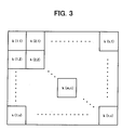
- Fig. 3 is a diagram showing the correction table used to correct the image pickup data by the AGC 112.
- Pieces of data k(1,1), ... and k(h,v) are correction data included in the correction table and correspond to each pixel of the CCD 102, respectively. If the CCD 102 has three million pixels and symbols h and v are set to be as far as 2048 and 1536, respectively, then the correction table can be set so that all the pixels of the CCD 102 can individually be corrected.
- the CPU 109 reads the respective data k(1,1), ... and k(h,v) of the correction table shown in Fig. 3 from the EEPROM 107 and outputs the respective data to the AGC 111.
- the AGC 111 performs gain control processing while correcting the gains of the respective pixels obtained in such a manner as ordinary AE operation, based on the correction data input from the CPU 109.
- the digital camera first acquires information on the distance of the digital camera to a subject using the number of pulses which are generated during AF operation (step S401).
- the subject is photographed using a flash (step S402).
- a signal (image pickup data) output from the CCD 102 is subjected to CDS processing (sampled and held) by the CDS 110 (step S403).
- the CPU 109 reads correction data from the correction table stored in the EEPROM 107 and sets the correction data in the AGC 111 (step S407).
- the AGC 111 conducts automatic gain control to the image pickup data while changing gains based on the set correction data (step S404).
- the image pickup data subjected to automatic gain control is converted to digital data by the ADC 112 (step S405) and then subjected to camera signal processing (step S406).
- Fig. 5 is a block diagram showing the configuration of the DSP/JPEG processor 104 which performs camera signal processing.
- Four pieces of raw data (R, Gr, Gb, and B) from the CCD are input into the DSP/JPEG processor 104 where these four pieces of data are branched into four color signals by a multiplexer 502 and fed to variable gain amplifiers 503a to 503d, respectively.
- the amplifiers 503a to 503d are used to perform correction and setting of white balance (WB) of the present invention.
- WB white balance
- the gains of the variable gain amplifiers 503a to 503d are controlled by the CPU.
- gain tables by as much as the number of all the pixels of the CCD are used.
- the tables are stored in the EEPROM 107 shown in Fig. 1.
- the DSP/JPEG processor 104 also includes an evaluation value generation block.
- the evaluation value generation block operates four integrated values of, for example, ⁇ R, ⁇ Gr, ⁇ Gb, and ⁇ B to thereby generate an evaluation value.
- the CPU 109 determines the state of the image from the evaluation value thus generated and performs setting of WB and corrections to the respective signals.
- the signals passing through the variable gain amplifiers 503a to 503d, respectively, are transformed to RGB signals by a 4 ⁇ 3 matrix 504 provided in the next stage and fed to a luminance signal/color signal processor.
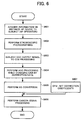
- Fig. 6 is a flow chart of processing performed by the DSP/JPEG processor 104 when the processor 104 corrects image pickup data.
- the digital camera first acquires information on the distance of the digital camera to a subject using the number of pulses which are generated during an AF operation (step S601).
- the subject is photographed using a flash (step S602).
- a signal (image pickup data) output from the CCD 102 is subjected to CDS processing (sampled and held) by the CDS 110 (step S603).
- the image pickup data thus CDS processed is output to the AGC 111 and the gain of the image pickup data is controlled by the AGC 111 (step S604).
- the ADC 112 converts the data to digital data (step S605) and further subjects the digital data to camera signal processing (step 606).
- the CPU 109 reads the correction coefficient table from the EEPROM 107 and sets correction coefficients as the coefficients of the variable gain amplifiers that are set according to the pixels of the CCD (step S607).
- the image pickup device of the first embodiment explained so far, it is possible to provide an image pickup device which can prevent the degradation of image quality due to an uneven luminous intensity distribution and which can form a high-quality image even if a subject is photographed using the flash from a relatively short distance.
- the image pickup device of the first embodiment there is no need to locate the flash at a position near the optical system in the digital camera, thereby making it possible to improve the degree of freedom to design the layout of the digital camera.
- the hardware configurations of the circuits and the flash are not changed. Therefore, it is possible to prevent the circuits mounted on the digital camera from being complicated in configuration, made large in size and to prevent cost from increasing. Thus, it is possible to correct the uneven luminous intensity distribution without preventing the digital camera from. being made smaller in size and lighter in weight and preventing the cost thereof from increasing.
- the digital image pickup device normally performs shading correction to correct the uneven luminous intensity distribution of an image pickup region which occurs because of the shading.
- Figs. 7A and 7B explain an uneven luminous intensity distribution caused by shading.
- the uneven luminous intensity distribution caused by shading is represented as a decrease in the light quantity of the end portions of the line L as shown in Fig. 7B.
- a correction characteristic for subjecting image pickup data to shading correction can be also added to the correction table.
- the correction characteristic is an opposite characteristic to the light quantity distribution shown, for example, in Fig. 7B.
- the correction table or correction coefficient table of the gain amplifier is set in the EEPROM 107. More specifically, the correction table shows the opposite characteristic to the characteristic obtained by adding the light quantity distribution shown in Fig. 7B to the light quantity distribution shown in Fig. 2B.
- the image pickup device may include a switch 801 in addition to the constituent elements shown in Fig. 1.
- This switch 801 is used to select whether or not the image pickup data is to be corrected. Therefore, an operator can select execution or non-execution of the correction using the switch.
- the CPU 109 automatically detects an uneven luminous intensity distribution from the image pickup data picked up by the CCD 102 and determines whether or not correction is to be executed.
- the correction of image pickup data on a binary image such as a character image can be executed by lowering correction accuracy.
- the correction accuracy can be lowered by, for example, setting the resolution of the correction table to be coarse.
- the correction accuracy can be lowered by lowering the resolution (the number of bits) of each correction data k(m, n).
- a threshold table is generally required for processing of image pickup data for a binary image.
- the image pickup data for the binary image is processed using the threshold table in which thresholds multiplied by the respective correction data set in the correction table shown in Fig. 3 are set, and it is thereby possible to correct the uneven luminous intensity distribution caused by the flash simultaneously with the binarization of the image pickup data.
- An image pickup device of the second embodiment has the same configuration as that of the first embodiment, and therefore the constituent elements of the image pickup device are not explained or shown in the drawings partially.
- the EEPROM 107 holds a plurality of correction tables explained in the first embodiment.
- the CPU 109 corrects image pickup data using the correction table which corresponds to a distance between the device and a subject measured from the number of pulses which are generated when the auto-focusing section 101 is driven or the distance measured by an external AF sensor 901.
- the image pickup device of the second embodiment stores in the EEPROM 107 a plurality of correction tables which correspond to the distances between the digital camera and a subject, respectively.
- the CPU 109 measures the distance of the digital camera to the subject, selects and reads the correction table which corresponds to the obtained distance, and sets the read correction table in the AGC 111 or the DSP/JPEG process or 104.
- An uneven luminous intensity distribution during stroboscopic photographing changes according to the distance to the subject. Therefore, according to the image pickup device of the second embodiment, it is possible to correct the image pickup data using correction data which corresponds to an uneven luminous intensity distribution closer to an actual uneven luminous intensity distribution and to correct the image pickup data more appropriately.
- the image pickup device of the second embodiment corrects the image pickup data by linear interpolation using the correction table stored in the EEPROM 107. According to the image pickup device of the second embodiment, the image pickup data can be corrected more appropriately while the number of correction tables to be stored is suppressed.
- the image pickup device of the second embodiment is not limited to the configuration in which the distance of the device to the subject is measured from the number of pulses which are generated when the auto-focusing section 101 is driven.
- the image pickup device may also include an external AF sensor 901 as shown in Fig. 9. If including the external AF sensor 901, the image pickup device of the second embodiment selects the correction table which corresponds to the distance measured by the AF sensor 901 and uses the table for correcting the image pickup data.
- a third embodiment of this invention will be explained below, and an image pickup device of the third embodiment will be explained.
- the image pickup device of this embodiment has the same configuration as the image pickup device shown in Fig. 1 or Fig. 9. Therefore, the constituent elements of the image pickup device of this embodiment will not be explained or shown in the drawings partially.
- the third embodiment is provided to solve the problem as follows. That is, when a binary image is to be picked up, binarization accuracy is higher as signal level is higher. If the light emission quantity of the flash is increased excessively so as to increase the signal level, a white void or white voids may occur in a picked-up image.
- the CCD 102 controls the flash 108 so as to emit light at least twice in different light quantities to pickup an image of a subject.
- the CPU 109 then corrects image pickup data using the data for the images picked-up in different light quantities.
- the CPU 109 controls the CCD 102 and the flash 108 to photograph the subject twice. This photographing is performed by changing the quantity of light emitted from the flash.
- the larger quantity of light emission is set as light emission quantity 1 and the smaller quantity of light emission is set as light emission quantity 2.
- the light emission quantity 1 is set to a quantity in which a sufficient signal level for necessary binarization accuracy is obtained.
- the light emission quantity 2 is set to a quantity in which no white void occurs.
- the CPU 109 controls the CCD 102 to photograph a binary image of the subject in the light emission quantity 1 for the first time.
- Image pickup data (image pickup data 1) obtained by the first photographing is stored in the SDRAM 105.
- the image pickup data 1 is read and subjected to SD processing and JPEG processing.
- the CPU 109 then controls the CCD 102 to pick up the binary image in the light emission quantity 2.
- the image pickup data (image pickup data 2) obtained at this time is stored in a different area of the SDRAM 105 from that where the image pickup data 1 is stored, and subjected to the SD processing and JPEG processing.
- the uneven luminous intensity distribution of the image pickup data is corrected by the AGC 111 or the DSP/JPEG processor 104 during the respective processing in the same manner as that in the first and second embodiments.
- the CPU 109 then replaces a portion in the image pickup data 1 in which a white void occurs, with a corresponding portion in the image pickup data 2 to thereby correct the image pickup data 1.
- the CCD 102 is constituted to perform interlace reading, a time difference between the two stroboscopic photographing operations grows.
- the CCD 102 it is therefore desirable to employ a CCD for entire pixel reading which transfers accumulated charges at one time such as a frame transfer type CCD.
- Fig. 10 is a flow chart of processing performed by the image pickup device of the third embodiment.
- the flash 108 is controlled to emit stronger light (emit light in the light emission quantity 1) to photograph a subject (step S1001).
- Image pickup data obtained by this photographing is converted to digital data by the front end processor 103 and subjected to camera signal processing by the DSP/JPEG processor 104 (step S1002).
- the image pickup data subjected to the camera signal processing is denoted as Y data which indicates luminance in the flow chart.
- the Y data (Y1) obtained through the processing at step S1002 is stored in the SDRAM 105 (step S1003).
- the CPU 109 searches the address of a white void pixel from the stored Y1 data (step S1004) and stores the searched pixel address in, for example, a different area of the SDRAM 105.
- the CPU 109 controls the flash 108 to emit weaker light (emit light in the light emission quantity 2) to photograph the subject (step S1006).
- Image pickup data obtained by this photographing is converted to digital data by the front end processor 103 and subjected to the camera signal processing by the DSP/JPEG processor 104 (step S1007).
- Y data (Y2 data) obtained through the processing at step S1007 is stored in the SDRAM 105 (step S1008).
- the CPU 109 replaces the pixel at the address which is stored at step S1005 with a pixel at the corresponding address of the data Y2.
- the data Y1 in which the pixel is replaced is denoted as data Y (step S1009).
- the data Y is binarized under the control of the CPU 109 (step S1010), thereby completing the processing shown in Fig. 10.
- the binarized data Y is stored in, for example, the memory card 106.
- the binary image is to be picked up, it is possible to generate image pickup data using optimum data for the respective portions of the image and to prevent any white void from occurring in the center of the image while preventing the periphery of the image from darkening.
- the image pickup device can correct the data for a picked-up image based on the light quantity distribution when a subject is photographed using a flash. Therefore, it is advantageously possible to provide the image pickup device which can obtain a high-quality image irrespective of the distance of the device to the subject when the subject is photographed using the flash, and prevent the circuit configuration of the device from being upsized.
- the image pickup data can be more accurately corrected using the light quantity distribution correction table which corresponds to the distance measured by a distance measurement unit. Therefore, it is advantageously possible to provide the image pickup device which can obtain a higher-quality image irrespective of the distance of the device to a subject when the subject is photographed using the flash.
- the image pickup data can be corrected by linear interpolation using the light quantity distribution correction table stored in the correction table recording unit. Therefore, it is advantageously possible to deal with image pickup data if a subject is present at various distances from the device.
- the shading correction can be simultaneously executed with the correction of the light quantity distribution. Therefore, it is advantageously possible to provide the image pickup device which can obtain a high-quality image without lengthening the processing time.
- binarization processing can be simultaneously executed with the correction of image pickup data for a binary image. Therefore, it is advantageously possible to further reduce a calculation time required for correcting the binary image as compared to that required for correcting a multilevel image.
- the data for a picked-up image can be corrected using respective pieces of data for the image picked up in different light quantities. Therefore, it is advantageously possible to provide the image pickup device which can generate image pickup data using optimum data for the respective portions of the image and to simultaneously realize avoidance of darkening of the periphery of the image and prevention of occurrence of any white void in the center of the image.
- the image pickup method comprises correcting the data for a picked-up image based on the light quantity distribution when a subject is photographed using a flash. Therefore, it is advantageously possible to provide the image pickup method capable of obtaining a high-quality image irrespective of the distance of the image pickup device to the subject when the subject is photographed using the flash.
Landscapes
- Engineering & Computer Science (AREA)
- Multimedia (AREA)
- Signal Processing (AREA)
- Studio Devices (AREA)
- Stroboscope Apparatuses (AREA)
Applications Claiming Priority (2)
| Application Number | Priority Date | Filing Date | Title |
|---|---|---|---|
| JP2001270852 | 2001-09-06 | ||
| JP2001270852A JP2003087653A (ja) | 2001-09-06 | 2001-09-06 | 撮像装置 |
Publications (3)
| Publication Number | Publication Date |
|---|---|
| EP1292128A2 true EP1292128A2 (de) | 2003-03-12 |
| EP1292128A3 EP1292128A3 (de) | 2004-12-01 |
| EP1292128B1 EP1292128B1 (de) | 2011-06-01 |
Family
ID=19096454
Family Applications (1)
| Application Number | Title | Priority Date | Filing Date |
|---|---|---|---|
| EP02256194A Expired - Lifetime EP1292128B1 (de) | 2001-09-06 | 2002-09-06 | Vorrichtung und Verfahren zur Bildaufnahme |
Country Status (3)
| Country | Link |
|---|---|
| US (1) | US7212239B2 (de) |
| EP (1) | EP1292128B1 (de) |
| JP (1) | JP2003087653A (de) |
Cited By (2)
| Publication number | Priority date | Publication date | Assignee | Title |
|---|---|---|---|---|
| WO2007133898A1 (en) * | 2006-05-15 | 2007-11-22 | Zoran Corporation | Compensating for non-uniform illumination of object fields captured by a camera |
| US8478066B2 (en) | 2003-10-31 | 2013-07-02 | Mitsubishi Denki Kabushiki Kaisha | Image-correction method and image pickup apparatus |
Families Citing this family (12)
| Publication number | Priority date | Publication date | Assignee | Title |
|---|---|---|---|---|
| JP4280993B2 (ja) | 2003-12-24 | 2009-06-17 | ソニー株式会社 | 撮像装置及びその方法並びにプログラム |
| JP4976049B2 (ja) * | 2006-05-02 | 2012-07-18 | 株式会社リコー | 撮像装置 |
| US7755672B2 (en) * | 2006-05-15 | 2010-07-13 | Zoran Corporation | Techniques for modifying image field data obtained using illumination sources |
| US7702235B2 (en) | 2007-01-25 | 2010-04-20 | Research In Motion Limited | Handheld electronic device and camera providing flash compensation of images, and associated method |
| US8547457B2 (en) * | 2009-06-22 | 2013-10-01 | Empire Technology Development Llc | Camera flash mitigation |
| TWI392852B (zh) * | 2009-09-25 | 2013-04-11 | Primax Electronics Ltd | 利用自動對焦測量距離之可攜式電子設備以及利用自動對焦測量距離之方法 |
| US10005682B1 (en) | 2009-10-02 | 2018-06-26 | Tersano Inc. | Holding tank-less water ozonating system |
| JP5649409B2 (ja) | 2010-11-04 | 2015-01-07 | 株式会社東芝 | 画像処理装置 |
| JP6261366B2 (ja) * | 2014-02-17 | 2018-01-17 | オリンパス株式会社 | 撮影装置、ストロボ画像事前取得方法及びストロボ画像事前取得プログラム |
| JP6390163B2 (ja) | 2014-05-16 | 2018-09-19 | 株式会社リコー | 情報処理装置、情報処理方法およびプログラム |
| US10559095B2 (en) * | 2016-08-31 | 2020-02-11 | Canon Kabushiki Kaisha | Image processing apparatus, image processing method, and medium |
| WO2025148519A1 (en) * | 2024-01-08 | 2025-07-17 | Shenzhen Infinitech Co., Ltd. | Methods for obtaining digital images in low-light conditions and imaging devices for the same |
Citations (2)
| Publication number | Priority date | Publication date | Assignee | Title |
|---|---|---|---|---|
| WO1993004442A1 (en) | 1991-08-23 | 1993-03-04 | United Parcel Service Of America, Inc. | Method and apparatus for compensation for non-uniform illumination |
| EP1045573A2 (de) | 1999-04-16 | 2000-10-18 | Eastman Kodak Company | Verfahren und Vorrichtung zur Kompensation von digitalen Bildern seitens Lichtschwächung |
Family Cites Families (32)
| Publication number | Priority date | Publication date | Assignee | Title |
|---|---|---|---|---|
| US4745466A (en) * | 1983-03-06 | 1988-05-17 | Canon Kabushiki Kaisha | Digital color image processing apparatus with color masking processing unit addressed by a plurality of multi-bit color component signals using various combinations of the bits of the signals |
| JPS6265573A (ja) * | 1985-09-17 | 1987-03-24 | Seiko Koki Kk | 撮像装置 |
| US5144445A (en) * | 1989-12-26 | 1992-09-01 | Sanyo Electric Co., Ltd. | Solid-state image pickup apparatus having a plurality of photoelectric transducers arranged in a matrix |
| US5047861A (en) * | 1990-07-31 | 1991-09-10 | Eastman Kodak Company | Method and apparatus for pixel non-uniformity correction |
| JP3234832B2 (ja) | 1992-01-31 | 2001-12-04 | キヤノン株式会社 | 閃光発光制御装置 |
| JP3433954B2 (ja) | 1992-10-02 | 2003-08-04 | 富士写真フイルム株式会社 | 電子スチル・カメラおよびその制御方法 |
| JPH06294759A (ja) * | 1993-04-09 | 1994-10-21 | Nippon Steel Corp | 圧延工程におけるロール転写疵の検出方法 |
| JPH07284011A (ja) * | 1994-04-05 | 1995-10-27 | Ricoh Co Ltd | デジタル電子スチルカメラ |
| JPH0895114A (ja) | 1994-09-21 | 1996-04-12 | Copal Co Ltd | ズームカメラ |
| JPH08289287A (ja) | 1995-04-12 | 1996-11-01 | Ricoh Co Ltd | 音声信号・映像信号処理装置 |
| JPH08327886A (ja) | 1995-05-30 | 1996-12-13 | Fuji Photo Optical Co Ltd | ストロボ内蔵カメラ |
| JPH09181913A (ja) * | 1995-12-26 | 1997-07-11 | Olympus Optical Co Ltd | カメラシステム |
| US6151073A (en) * | 1996-03-28 | 2000-11-21 | Fotonation, Inc. | Intelligent camera flash system |
| JPH09322191A (ja) | 1996-03-29 | 1997-12-12 | Ricoh Co Ltd | 画像入力装置 |
| JP3392676B2 (ja) * | 1997-01-10 | 2003-03-31 | 三洋電機株式会社 | 固体撮像素子及びこれを用いた撮像装置 |
| JP3804192B2 (ja) * | 1997-06-25 | 2006-08-02 | 日本ビクター株式会社 | ストロボ撮影装置 |
| US5951625A (en) * | 1997-06-30 | 1999-09-14 | Truevision, Inc. | Interpolated lookup table circuit |
| JPH11242274A (ja) * | 1998-02-25 | 1999-09-07 | Fuji Photo Optical Co Ltd | カメラおよび写真プリントシステム |
| JP3576809B2 (ja) * | 1998-05-21 | 2004-10-13 | 富士写真フイルム株式会社 | 画像処理装置 |
| JP2000089289A (ja) | 1998-09-11 | 2000-03-31 | Minolta Co Ltd | カメラ |
| JP2000278598A (ja) | 1999-03-19 | 2000-10-06 | Minolta Co Ltd | デジタルカメラおよび記録媒体 |
| US6833862B1 (en) * | 1999-06-30 | 2004-12-21 | Logitech, Inc. | Image sensor based vignetting correction |
| JP2001016447A (ja) * | 1999-06-30 | 2001-01-19 | Minolta Co Ltd | 画像処理装置および画像処理方法、ならびに画像処理プログラムを記録した記録媒体 |
| US6366680B1 (en) * | 1999-11-22 | 2002-04-02 | Digimarc Corporation | Adjusting an electronic camera to acquire a watermarked image |
| GB2356996A (en) * | 1999-12-03 | 2001-06-06 | Hewlett Packard Co | Improvements to digital cameras |
| JP4212741B2 (ja) * | 1999-12-09 | 2009-01-21 | 株式会社リコー | 画像処理装置 |
| JP3603715B2 (ja) * | 2000-01-14 | 2004-12-22 | ミノルタ株式会社 | 測距装置および該測距装置を備えたカメラ |
| JP2001223943A (ja) * | 2000-02-10 | 2001-08-17 | Fuji Photo Film Co Ltd | 撮像装置 |
| JP2001238127A (ja) * | 2000-02-21 | 2001-08-31 | Fuji Photo Film Co Ltd | カメラ |
| JP2001268326A (ja) * | 2000-03-23 | 2001-09-28 | Minolta Co Ltd | 画像処理装置および撮像装置 |
| JP2001275029A (ja) * | 2000-03-28 | 2001-10-05 | Minolta Co Ltd | デジタルカメラ、その画像信号処理方法及び記録媒体 |
| US20020015103A1 (en) * | 2000-07-25 | 2002-02-07 | Zhimin Shi | System and method of capturing and processing digital images with depth channel |
-
2001
- 2001-09-06 JP JP2001270852A patent/JP2003087653A/ja active Pending
-
2002
- 2002-09-06 EP EP02256194A patent/EP1292128B1/de not_active Expired - Lifetime
- 2002-09-06 US US10/235,715 patent/US7212239B2/en not_active Expired - Fee Related
Patent Citations (2)
| Publication number | Priority date | Publication date | Assignee | Title |
|---|---|---|---|---|
| WO1993004442A1 (en) | 1991-08-23 | 1993-03-04 | United Parcel Service Of America, Inc. | Method and apparatus for compensation for non-uniform illumination |
| EP1045573A2 (de) | 1999-04-16 | 2000-10-18 | Eastman Kodak Company | Verfahren und Vorrichtung zur Kompensation von digitalen Bildern seitens Lichtschwächung |
Cited By (3)
| Publication number | Priority date | Publication date | Assignee | Title |
|---|---|---|---|---|
| US8478066B2 (en) | 2003-10-31 | 2013-07-02 | Mitsubishi Denki Kabushiki Kaisha | Image-correction method and image pickup apparatus |
| WO2007133898A1 (en) * | 2006-05-15 | 2007-11-22 | Zoran Corporation | Compensating for non-uniform illumination of object fields captured by a camera |
| US8259179B2 (en) | 2006-05-15 | 2012-09-04 | Csr Technology Inc. | Compensating for non-uniform illumination of object fields captured by a camera |
Also Published As
| Publication number | Publication date |
|---|---|
| EP1292128A3 (de) | 2004-12-01 |
| US7212239B2 (en) | 2007-05-01 |
| JP2003087653A (ja) | 2003-03-20 |
| EP1292128B1 (de) | 2011-06-01 |
| US20030044066A1 (en) | 2003-03-06 |
Similar Documents
| Publication | Publication Date | Title |
|---|---|---|
| US20070076103A1 (en) | Image pickup apparatus and image processing method | |
| US8482618B2 (en) | Reduction of motion-induced blur in images | |
| EP1292128B1 (de) | Vorrichtung und Verfahren zur Bildaufnahme | |
| US7336306B2 (en) | Solid-state image sensor efficiently utilizing its dynamic range and image pickup apparatus using the same | |
| US7598986B2 (en) | Image pick-up apparatus and white balance control method | |
| US20040239790A1 (en) | Image capturing apparatus | |
| US8155472B2 (en) | Image processing apparatus, camera, image processing program product and image processing method | |
| US7643072B2 (en) | Signal processing method for image capturing apparatus, and image capturing apparatus including calculating image transfer efficiency | |
| JP4346289B2 (ja) | 撮像装置 | |
| US8026965B2 (en) | Image pickup apparatus and method for controlling the same | |
| JP4763469B2 (ja) | 固体撮像装置および画像入力装置、ならびにその画像補正方法 | |
| JP4305200B2 (ja) | 撮像装置および方法、並びにプログラム | |
| US7777793B2 (en) | Signal processor having A/D conversion unit and operation part | |
| US7697043B2 (en) | Apparatus for compensating for color shading on a picture picked up by a solid-state image sensor over a broad dynamic range | |
| JP2010093759A (ja) | 撮像センサ及び撮像装置 | |
| EP1578109B1 (de) | Bilderzeugungsgerät, Bildverarbeitungsvorrichtung, -system und -verfahren | |
| JP4732795B2 (ja) | 固体撮像装置および画像補正方法 | |
| JP4276847B2 (ja) | 撮像装置 | |
| EP4287640B1 (de) | Bildverarbeitungsvorrichtung, steuerverfahren dafür und computerprogramm | |
| US8330842B2 (en) | Amplifier control device and recording non-transitory medium | |
| JP4769851B2 (ja) | 撮像装置 | |
| JP3667915B2 (ja) | スキャナおよび対象画像読取方法 | |
| JP2005260573A (ja) | 電子カメラ、カメラシステムおよび電子カメラの黒点補正方法 | |
| JP2003143491A (ja) | 撮像装置 | |
| JP2010251855A (ja) | 撮像装置 |
Legal Events
| Date | Code | Title | Description |
|---|---|---|---|
| PUAI | Public reference made under article 153(3) epc to a published international application that has entered the european phase |
Free format text: ORIGINAL CODE: 0009012 |
|
| 17P | Request for examination filed |
Effective date: 20020921 |
|
| AK | Designated contracting states |
Kind code of ref document: A2 Designated state(s): AT BE BG CH CY CZ DE DK EE ES FI FR GB GR IE IT LI LU MC NL PT SE SK TR |
|
| AX | Request for extension of the european patent |
Extension state: AL LT LV MK RO SI |
|
| PUAL | Search report despatched |
Free format text: ORIGINAL CODE: 0009013 |
|
| AK | Designated contracting states |
Kind code of ref document: A3 Designated state(s): AT BE BG CH CY CZ DE DK EE ES FI FR GB GR IE IT LI LU MC NL PT SE SK TR |
|
| AX | Request for extension of the european patent |
Extension state: AL LT LV MK RO SI |
|
| RIC1 | Information provided on ipc code assigned before grant |
Ipc: 7H 04N 5/235 A Ipc: 7H 04N 5/217 B Ipc: 7H 04N 5/243 B |
|
| AKX | Designation fees paid |
Designated state(s): DE ES FR GB IT NL |
|
| 17Q | First examination report despatched |
Effective date: 20090211 |
|
| GRAC | Information related to communication of intention to grant a patent modified |
Free format text: ORIGINAL CODE: EPIDOSCIGR1 |
|
| GRAP | Despatch of communication of intention to grant a patent |
Free format text: ORIGINAL CODE: EPIDOSNIGR1 |
|
| RIN1 | Information on inventor provided before grant (corrected) |
Inventor name: SAKAGUCHI, NORIHIRO,RICOH COMPANY, LTD. |
|
| GRAS | Grant fee paid |
Free format text: ORIGINAL CODE: EPIDOSNIGR3 |
|
| GRAA | (expected) grant |
Free format text: ORIGINAL CODE: 0009210 |
|
| AK | Designated contracting states |
Kind code of ref document: B1 Designated state(s): DE ES FR GB IT NL |
|
| REG | Reference to a national code |
Ref country code: GB Ref legal event code: FG4D |
|
| REG | Reference to a national code |
Ref country code: DE Ref legal event code: R096 Ref document number: 60240186 Country of ref document: DE Effective date: 20110714 |
|
| REG | Reference to a national code |
Ref country code: NL Ref legal event code: VDEP Effective date: 20110601 |
|
| PG25 | Lapsed in a contracting state [announced via postgrant information from national office to epo] |
Ref country code: ES Free format text: LAPSE BECAUSE OF FAILURE TO SUBMIT A TRANSLATION OF THE DESCRIPTION OR TO PAY THE FEE WITHIN THE PRESCRIBED TIME-LIMIT Effective date: 20110912 |
|
| PG25 | Lapsed in a contracting state [announced via postgrant information from national office to epo] |
Ref country code: NL Free format text: LAPSE BECAUSE OF FAILURE TO SUBMIT A TRANSLATION OF THE DESCRIPTION OR TO PAY THE FEE WITHIN THE PRESCRIBED TIME-LIMIT Effective date: 20110601 |
|
| PLBE | No opposition filed within time limit |
Free format text: ORIGINAL CODE: 0009261 |
|
| STAA | Information on the status of an ep patent application or granted ep patent |
Free format text: STATUS: NO OPPOSITION FILED WITHIN TIME LIMIT |
|
| 26N | No opposition filed |
Effective date: 20120302 |
|
| PG25 | Lapsed in a contracting state [announced via postgrant information from national office to epo] |
Ref country code: IT Free format text: LAPSE BECAUSE OF FAILURE TO SUBMIT A TRANSLATION OF THE DESCRIPTION OR TO PAY THE FEE WITHIN THE PRESCRIBED TIME-LIMIT Effective date: 20110601 |
|
| REG | Reference to a national code |
Ref country code: DE Ref legal event code: R097 Ref document number: 60240186 Country of ref document: DE Effective date: 20120302 |
|
| REG | Reference to a national code |
Ref country code: FR Ref legal event code: PLFP Year of fee payment: 15 |
|
| REG | Reference to a national code |
Ref country code: FR Ref legal event code: PLFP Year of fee payment: 16 |
|
| PGFP | Annual fee paid to national office [announced via postgrant information from national office to epo] |
Ref country code: GB Payment date: 20170921 Year of fee payment: 16 Ref country code: FR Payment date: 20170928 Year of fee payment: 16 Ref country code: DE Payment date: 20170928 Year of fee payment: 16 |
|
| REG | Reference to a national code |
Ref country code: DE Ref legal event code: R119 Ref document number: 60240186 Country of ref document: DE |
|
| GBPC | Gb: european patent ceased through non-payment of renewal fee |
Effective date: 20180906 |
|
| PG25 | Lapsed in a contracting state [announced via postgrant information from national office to epo] |
Ref country code: DE Free format text: LAPSE BECAUSE OF NON-PAYMENT OF DUE FEES Effective date: 20190402 |
|
| PG25 | Lapsed in a contracting state [announced via postgrant information from national office to epo] |
Ref country code: FR Free format text: LAPSE BECAUSE OF NON-PAYMENT OF DUE FEES Effective date: 20180930 |
|
| PG25 | Lapsed in a contracting state [announced via postgrant information from national office to epo] |
Ref country code: GB Free format text: LAPSE BECAUSE OF NON-PAYMENT OF DUE FEES Effective date: 20180906 |