EP4287640B1 - Bildverarbeitungsvorrichtung, steuerverfahren dafür und computerprogramm - Google Patents
Bildverarbeitungsvorrichtung, steuerverfahren dafür und computerprogramm Download PDFInfo
- Publication number
- EP4287640B1 EP4287640B1 EP23171241.5A EP23171241A EP4287640B1 EP 4287640 B1 EP4287640 B1 EP 4287640B1 EP 23171241 A EP23171241 A EP 23171241A EP 4287640 B1 EP4287640 B1 EP 4287640B1
- Authority
- EP
- European Patent Office
- Prior art keywords
- image data
- image
- gain
- exposure
- processing apparatus
- Prior art date
- Legal status (The legal status is an assumption and is not a legal conclusion. Google has not performed a legal analysis and makes no representation as to the accuracy of the status listed.)
- Active
Links
Images


Classifications
-
- H—ELECTRICITY
- H04—ELECTRIC COMMUNICATION TECHNIQUE
- H04N—PICTORIAL COMMUNICATION, e.g. TELEVISION
- H04N23/00—Cameras or camera modules comprising electronic image sensors; Control thereof
- H04N23/70—Circuitry for compensating brightness variation in the scene
- H04N23/73—Circuitry for compensating brightness variation in the scene by influencing the exposure time
-
- H—ELECTRICITY
- H04—ELECTRIC COMMUNICATION TECHNIQUE
- H04N—PICTORIAL COMMUNICATION, e.g. TELEVISION
- H04N25/00—Circuitry of solid-state image sensors [SSIS]; Control thereof
- H04N25/60—Noise processing, e.g. detecting, correcting, reducing or removing noise
- H04N25/62—Detection or reduction of noise due to excess charges produced by the exposure, e.g. smear, blooming, ghost image, crosstalk or leakage between pixels
-
- G—PHYSICS
- G06—COMPUTING OR CALCULATING; COUNTING
- G06T—IMAGE DATA PROCESSING OR GENERATION, IN GENERAL
- G06T5/00—Image enhancement or restoration
- G06T5/50—Image enhancement or restoration using two or more images, e.g. averaging or subtraction
-
- G—PHYSICS
- G06—COMPUTING OR CALCULATING; COUNTING
- G06T—IMAGE DATA PROCESSING OR GENERATION, IN GENERAL
- G06T5/00—Image enhancement or restoration
- G06T5/70—Denoising; Smoothing
-
- G—PHYSICS
- G06—COMPUTING OR CALCULATING; COUNTING
- G06T—IMAGE DATA PROCESSING OR GENERATION, IN GENERAL
- G06T5/00—Image enhancement or restoration
- G06T5/90—Dynamic range modification of images or parts thereof
- G06T5/92—Dynamic range modification of images or parts thereof based on global image properties
-
- H—ELECTRICITY
- H04—ELECTRIC COMMUNICATION TECHNIQUE
- H04N—PICTORIAL COMMUNICATION, e.g. TELEVISION
- H04N23/00—Cameras or camera modules comprising electronic image sensors; Control thereof
- H04N23/50—Constructional details
-
- H—ELECTRICITY
- H04—ELECTRIC COMMUNICATION TECHNIQUE
- H04N—PICTORIAL COMMUNICATION, e.g. TELEVISION
- H04N23/00—Cameras or camera modules comprising electronic image sensors; Control thereof
- H04N23/50—Constructional details
- H04N23/55—Optical parts specially adapted for electronic image sensors; Mounting thereof
-
- H—ELECTRICITY
- H04—ELECTRIC COMMUNICATION TECHNIQUE
- H04N—PICTORIAL COMMUNICATION, e.g. TELEVISION
- H04N23/00—Cameras or camera modules comprising electronic image sensors; Control thereof
- H04N23/60—Control of cameras or camera modules
-
- H—ELECTRICITY
- H04—ELECTRIC COMMUNICATION TECHNIQUE
- H04N—PICTORIAL COMMUNICATION, e.g. TELEVISION
- H04N23/00—Cameras or camera modules comprising electronic image sensors; Control thereof
- H04N23/70—Circuitry for compensating brightness variation in the scene
-
- H—ELECTRICITY
- H04—ELECTRIC COMMUNICATION TECHNIQUE
- H04N—PICTORIAL COMMUNICATION, e.g. TELEVISION
- H04N23/00—Cameras or camera modules comprising electronic image sensors; Control thereof
- H04N23/70—Circuitry for compensating brightness variation in the scene
- H04N23/71—Circuitry for evaluating the brightness variation
-
- H—ELECTRICITY
- H04—ELECTRIC COMMUNICATION TECHNIQUE
- H04N—PICTORIAL COMMUNICATION, e.g. TELEVISION
- H04N23/00—Cameras or camera modules comprising electronic image sensors; Control thereof
- H04N23/70—Circuitry for compensating brightness variation in the scene
- H04N23/741—Circuitry for compensating brightness variation in the scene by increasing the dynamic range of the image compared to the dynamic range of the electronic image sensors
-
- H—ELECTRICITY
- H04—ELECTRIC COMMUNICATION TECHNIQUE
- H04N—PICTORIAL COMMUNICATION, e.g. TELEVISION
- H04N23/00—Cameras or camera modules comprising electronic image sensors; Control thereof
- H04N23/70—Circuitry for compensating brightness variation in the scene
- H04N23/76—Circuitry for compensating brightness variation in the scene by influencing the image signals
-
- H—ELECTRICITY
- H04—ELECTRIC COMMUNICATION TECHNIQUE
- H04N—PICTORIAL COMMUNICATION, e.g. TELEVISION
- H04N23/00—Cameras or camera modules comprising electronic image sensors; Control thereof
- H04N23/80—Camera processing pipelines; Components thereof
- H04N23/81—Camera processing pipelines; Components thereof for suppressing or minimising disturbance in the image signal generation
-
- H—ELECTRICITY
- H04—ELECTRIC COMMUNICATION TECHNIQUE
- H04N—PICTORIAL COMMUNICATION, e.g. TELEVISION
- H04N25/00—Circuitry of solid-state image sensors [SSIS]; Control thereof
- H04N25/50—Control of the SSIS exposure
- H04N25/57—Control of the dynamic range
-
- H—ELECTRICITY
- H04—ELECTRIC COMMUNICATION TECHNIQUE
- H04N—PICTORIAL COMMUNICATION, e.g. TELEVISION
- H04N5/00—Details of television systems
- H04N5/222—Studio circuitry; Studio devices; Studio equipment
- H04N5/262—Studio circuits, e.g. for mixing, switching-over, change of character of image, other special effects ; Cameras specially adapted for the electronic generation of special effects
- H04N5/265—Mixing
-
- G—PHYSICS
- G06—COMPUTING OR CALCULATING; COUNTING
- G06T—IMAGE DATA PROCESSING OR GENERATION, IN GENERAL
- G06T2207/00—Indexing scheme for image analysis or image enhancement
- G06T2207/10—Image acquisition modality
- G06T2207/10141—Special mode during image acquisition
- G06T2207/10144—Varying exposure
-
- G—PHYSICS
- G06—COMPUTING OR CALCULATING; COUNTING
- G06T—IMAGE DATA PROCESSING OR GENERATION, IN GENERAL
- G06T2207/00—Indexing scheme for image analysis or image enhancement
- G06T2207/20—Special algorithmic details
- G06T2207/20172—Image enhancement details
- G06T2207/20208—High dynamic range [HDR] image processing
Definitions
- the present invention relates to an image processing apparatus, a control method thereof, and a computer program.
- a usage ratio between an overexposed image and an appropriate image are determined and the images are composited. It is similar for an intermediate region of a range and the like between an appropriately exposed portion and a bright portion.
- a mix table in which a usage ratio for each image is thus defined for each brightness is held in advance, and the images are composited using the table.
- an image capturing device including two column circuits for an output signal from a unit pixel, separately holding gains of amplifiers in the column circuits, and capable of outputting images of different gains.
- the image capturing device can output two images of different gains (high gain and low gain images) with a single exposure.
- Compositing two images according to DGO has advantages, such as processing for aligning the two images being unnecessary and good compositing being possible for a moving subject. Accordingly, DGO is well suited to high dynamic range (HDR) compositing for obtaining an image with an expanded dynamic range.
- HDR high dynamic range
- compositing coefficients are outputted based on the ratios at which the images are used when compositing. That is, the document basically targets images of different sensitivities but of the same exposure and does not mention anything about reducing noise occurring when compositing images of different brightnesses.
- Document US 11 184 565 B2 discloses an image pickup apparatus that enables amplifying a signal based on output of a photoelectric conversion unit, with a plurality of gains to obtain an image having a better S/N ratio in accordance with gain settings in.
- An image pickup element provided in an image pickup apparatus has a photoelectric conversion unit in which unit pixels are arranged in a matrix and a signal voltage is generating by photoelectric conversion.
- a column amplifier of the image pickup element can amplify the signal voltage photoelectrically converted with a plurality of gains.
- An image pickup element control unit performs drive control of the image pickup element to perform gain settings.
- An image composition unit performs image composition by using a plurality of image signals having different gains.
- the image pickup element control unit changes a value of a second gain that is smaller than that of a first gain among the gains and performs control so as not to change the value of the first gain.
- Document JP 2006 003 740 A discloses a camera capable of easily performing high-quality photographing, without using strobe light emission.
- the camera calculates exposure index, corresponding to the luminance of a subject measured by a photometer section and exerts exposure control based upon the exposure index.
- the exposure control is exerted using an exposure index obtained by making prescribed correction to a regular exposure index.
- the present invention has been made in view of such problems and provides a technique for high dynamic range compositing processing in which noise is reduced in image compositing for when exposure is largely different.
- the present invention in its first aspect provides an image processing apparatus as specified in claims 1 to 7.
- the present invention in its second aspect provides a control method of an image processing apparatus as specified in claim 8.
- the present invention in its third aspect provides a computer program as specified in claim 9.
- the image capturing apparatus includes an optical lens 101, an image capturing device 102, an image acquiring unit 103, an image compositing unit 104, a signal processing unit 105, an exposure control unit 107, an image capturing device control unit 108, a control unit 150, and a UI 160.
- the control unit 150 is responsible for controlling the entire apparatus and is configured by a processor, a ROM for storing programs to be executed by the processor and various parameters, and a RAM to be used as a working area.
- the UI 160 is configured by various buttons and keys typified by a shutter button, a display unit, and a touch panel provided in front of the display unit and functions as a user interface between a user and the image capturing apparatus.
- the optical lens 101 captures light of a subject and forms an image of the subject on an image capturing surface of the image capturing device 102.
- the image capturing device 102 converts the optical image formed on the image capturing surface into electric signals and outputs the electric signals.
- Typical examples include a charge coupled device (CCD) image sensor, a CMOS image sensor, and the like.
- CCD charge coupled device
- CMOS image sensor CMOS image sensor
- Some image capturing devices directly output analog video signals while others perform analog-digital conversion processing and output digital data, such as low voltage differential signaling (LVDS).
- LVDS low voltage differential signaling
- the image capturing device 102 in the embodiment allows output of image data of two different gains by amplifying each of the electric signals obtained by a single exposure with two types of gains.
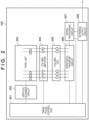
- FIG. 2 a circuit configuration of the image capturing device 102 used in the embodiment is illustrated in FIG. 2 .
- a timing pulse control unit 201 controls the operation of the image capturing device 102 by supplying an operation clock signal CLK for each block of the image capturing device 102 and by supplying a timing signal to each block.
- a vertical scanning circuit 202 performs timing control for sequentially reading out, in one frame, voltages represented by pixel signals accumulated by a pixel unit 203.
- video signals are sequentially read out line by line from a top line to a bottom line in one frame.
- the pixel unit 203 includes a plurality of photoelectric conversion devices arranged in a matrix. Each of the photoelectric conversion devices generates an electrical signal corresponding to an amount of incident light and outputs the electric signal.
- the pixel unit 203 converts captured light into charge and accumulates the charge in capacitor floating diffusions (FDs).
- FDs capacitor floating diffusions
- a capacitance of an FD can be changed between large and small, and signal noise is improved by changing the capacitance according to ISO sensitivity.
- the FD is used with the capacitance being set to large for a low ISO sensitivity and to small for a high ISO sensitivity.
- the capacitance for accumulating charge is common to the two gains.
- the capacitance is not limited to two types, large and small, and a setting of three or more levels may be possible.
- a column amplifier 204 is used for electrically amplifying signals read out from the pixel unit 203. By amplifying the signals in the column amplifier 204, signal levels of pixels are amplified with respect to the noise to be outputted by a subsequent column ADC 205, thereby equally improving signal noise. Further, a structure is such that a gain of the column amplifier 204 can be changed by the timing pulse control unit 201.
- the image capturing device 102 includes two input memories in the column amplifier unit 204 for generating a high dynamic range (HDR) image and can output two types of gains by changing the gain of the column amplifier.
- HDR high dynamic range
- the column ADC 205 converts signals from the column amplifier 204 from analog to digital. Then, the column ADC 205 supplies digitalized signals (digital image data) to a horizontal transfer circuit 206. Horizontal transfer circuit 206 outputs line-by-line digital image data to the signal processing circuit 207.
- the signal processing circuit 207 is a circuit for digitally performing signal processing and can add an offset value of a certain amount in digital processing as well as easily perform gain calculation by performing shift calculation and multiplication.
- the signal processing circuit 207 passes the processed image data to an external output circuit 208.
- the external output circuit 208 supplies the image data as image data to an external device (image acquiring unit 193).
- the image compositing unit 104 composites image data (image data with two types of gains) for generating an HDR image, outputted from the image capturing device 102, into an HDR image by using a predetermined compositing method.
- An example is a compositing method in which a high gain image (hereinafter, referred to as an H image) is used for a dark portion, a low gain image (hereinafter, referred to as an L image) is used for a bright portion, and a usage ratio of each image for weighted addition of the H image and the L image is determined for an intermediate region between, for example, a dark portion and a bright portion.
- a compositing algorithm is not limited so long as it is a technique for compositing two image of different gains.
- the image compositing unit 104 generates compositing ratio information allowing a compositing ratio between the H image and the L image for each pixel at the time of compositing processing to be identified and attaches the generated compositing ratio information to a composite image.
- a compositing ratio is generated for each pixel; however, information may be information holding compositing information of only a mixed region, and the compositing information is not limited so long as the compositing ratio can be determined.
- the signal processing unit 105 performs a pixel addition function as a typical image processing function of the image capturing apparatus and performs various kinds of image processing, such as noise reduction, gamma correction, knee correction, digital gain, defect correction, and the like.
- the image acquiring unit 103 and the signal processing unit 105 also include a storage circuit for storing setting values necessary for respective corrections and image processing, not explicitly illustrated in the block diagram.
- a signal storage unit 106 stores an HDR composite image and video signals received from the image compositing unit 104 and the signal processing unit 105 in a storage medium (not illustrated).
- the storage medium may be a storage apparatus, such as an HDD; a non-volatile memory card, such as an SD card; or the like, and a type thereof does not matter.
- the exposure control unit 107 can calculate an exposure amount from video signal information received from the image acquiring unit 103.
- the exposure control unit 107 in the present embodiment acquires the exposure amount with a method of calculating the exposure amount from the video signal information but may acquire the exposure amount from a control exposure at the time of image capturing.
- the exposure control unit 107 determines the operation of the image capturing device control unit 108 based on information related to the calculated exposure amount and transmits a parameter thereof to the image capturing device control unit 108.
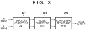
- FIG. 3 is a block diagram of the image compositing unit 104 and illustrates a configuration until compositing processing in which the H image and the L image for which two types of gains have been applied, outputted from the image acquiring unit 103, are used.
- the processing equivalent to the illustration may be implemented by hardware or by a processor executing a control program.
- An exposure correcting unit 301 causes the gains of the inputted H image and L image to be the same. This is to cause output for an input signal to be linear after the images have been composited into a single image.
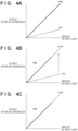
- FIGS. 4A to 4C are graphs in which an amount of input light of the H image and an amount of input light of the L image are on a horizontal axis, and an output code after AD conversion is on a vertical axis.
- Candela (cd) is mainly used for units of the amount of light of the horizontal axis.
- the exposure correcting unit 301 applies a gain to the L image for the brightnesses of the H image and the L image to match.
- FIG. 4C is an example in which the brightness of the L image has been adjusted to that of the H image.
- An exposure-corrected image for which the brightness has been adjusted to that of the H image by exposure correction on the L image is hereinafter referred to as a low gain 2 image (hereinafter referred to as an L2 image).
- a gain for obtaining the L2 image from the L image depends on the exposure difference between the H image and the L image.
- the exposure difference depends on exposure parameters (such as a shutter speed and an aperture) at the time of image capturing for obtaining an HDR composite image.
- the exposure correcting unit 301 when the exposure difference between the H image and the L image at the time of image capturing by the image capturing device 102 is "-3 EV", the exposure correcting unit 301 generates the L2 image by performing exposure correction according to a gain shift amount of "+4 levels" for the L image.
- a noise correcting unit 302 performs correction for noise reduction on the L2 image.
- the noise correcting unit 302 performs filter processing in which an average value (or a weighted average value) of a pixel of interest to be corrected (one of R, G, and B pixels of a Bayer array) in the L2 image and four pixels closest to the pixel of interest and of the same color is used as a corrected pixel value of the pixel of interest.
- a size of a filter may be appropriately set or may be selected by the user.
- the compositing processing unit 303 generates HDR image data by performing compositing processing using the H image and the L2 image received via the noise correcting unit 302 and outputs the HDR image data.
- a value of a pixel at coordinates (x, y) of the HDR image to be outputted is expressed as P HDR (x, y)
- a value of a pixel at coordinates (x, y) of the H image is expressed as P H (x, y)
- a value of a pixel at coordinates (x, y) of the L2 image is expressed as P L2 (x, y).
- a threshold for determining a highlight region is defined as T_H, and a threshold for determining a dark region is defined as T_L.
- a value of a pixel is larger than the threshold T_H, that pixel is determined to be a pixel of the highlight region.
- a value of a pixel is smaller than the threshold T_L, that pixel is determined to be a pixel of the dark region.
- a value of a pixel is the threshold T_L or more and the threshold T_H or less, that pixel is determined to be that of the intermediate region.
- the compositing processing unit 303 determines a value of each pixel of the HDR image according to the following.
Landscapes
- Engineering & Computer Science (AREA)
- Multimedia (AREA)
- Signal Processing (AREA)
- Physics & Mathematics (AREA)
- General Physics & Mathematics (AREA)
- Theoretical Computer Science (AREA)
- Studio Devices (AREA)
- Image Processing (AREA)
- Exposure Control For Cameras (AREA)
- Transforming Light Signals Into Electric Signals (AREA)
Claims (9)
- Bildverarbeitungsvorrichtung (101-108, 150, 160), die betreibbar ist, um erste Bilddaten und zweite Bilddaten zu verarbeiten, die von einer Bildaufnahmeeinrichtung (102) erhalten werden, die in der Lage ist, ein durch photoelektrische Umwandlung erhaltenes Signal mit einer ersten Verstärkung und einer zweiten Verstärkung, die niedriger als die erste Verstärkung ist, zu verstärken, um entsprechend die ersten Bilddaten und die zweiten Bilddaten zu erhalten, wobei die Vorrichtung aufweist:eine Belichtungskorrektureinrichtung (301) zum Anwenden einer Verstärkung auf die zweiten Bilddaten, so dass die Helligkeit des zweiten Bildes der Helligkeit des ersten Bildes entspricht;wobei die Verstärkung, die auf die zweiten Bilddaten angewendet wird, auf einer Belichtungsdifferenz zwischen den ersten und zweiten Bilddaten basiert;eine Rauschkorrektureinrichtung (302) zum Anwenden eines Rauschreduzierungsprozesses auf die zweiten Bilddaten, deren Helligkeit korrigiert wurde; undeine Erzeugungseinrichtung (303) zum Erzeugen zusammengesetzter Bilddaten durch Zusammensetzen der zweiten Bilddaten, auf die der Rauschreduzierungsprozess durch die Rauschkorrektureinrichtung angewendet wurde, und der ersten Bilddaten.
- Bildverarbeitungsvorrichtung gemäß Anspruch 1, wobei die Rauschkorrektureinrichtung (302) als den Rauschreduzierungsprozess eine Filterverarbeitung, die einen Wert eines betreffenden Pixels mit Werten anderer Pixel in der Nähe des betreffenden Pixels mittelt, auf die zweiten Bilddaten anwendet.
- Bildverarbeitungsvorrichtung gemäß Anspruch 1 oder 2, weiterhin mit:einer Bestimmungseinrichtung (S604) zum Bestimmen, ob der Rauschreduzierungsprozess anzuwenden ist, gemäß einer Belichtungsdifferenz zwischen den ersten Bilddaten und den zweiten Bilddaten, wobei die Belichtungsdifferenz auf Belichtungsparametern oder einer Kontrollbelichtung basiert, die verwendet werden, um das Signal zu erhalten; undwobei die Rauschkorrektureinrichtung den Rauschreduzierungsprozess nur in einem Fall auf die zweiten Bilddaten anwendet, in dem bestimmt ist, dass der Rauschreduzierungsprozess angewendet werden soll.
- Bildverarbeitungsvorrichtung gemäß Anspruch 3, wobeidie Bestimmungseinrichtung (S604) die Belichtungsdifferenz durch Bezugnahme auf eine vorbestimmte Tabelle basierend auf den Belichtungsparametern beschafft, undder Betrag der Verstärkung, der durch die Belichtungskorrektureinrichtung (301) auf die zweiten Bilddaten angewendet wird, basierend auf der Belichtungsdifferenz bestimmt wird.
- Bildverarbeitungsvorrichtung gemäß einem der Ansprüche 1 bis 4, wobei die Erzeugungseinrichtung (303) zusammengesetzte Bilddaten mit hohem Dynamikbereich (HDR) erzeugt.
- Bildverarbeitungsvorrichtung gemäß Anspruch 5, wobei die Erzeugungseinrichtung (303) weiterhin Informationen erzeugt (S607), die ein Zusammensetzungsverhältnis jedes Pixels in den zwei Bilddaten angeben, die bei der Erzeugung der zusammengesetzten HDR-Bilddaten verwendet werden.
- Bildverarbeitungsvorrichtung gemäß einem der Ansprüche 1 bis 6, wobei die Bildaufnahmeeinrichtung (102) in der Bildverarbeitungsvorrichtung umfasst ist.
- Steuerungsverfahren einer Bildverarbeitungsvorrichtung, die betreibbar ist, um erste Bilddaten und zweite Bilddaten zu verarbeiten, die von einer Bildaufnahmeeinrichtung (102) erhalten werden, die in der Lage ist, ein durch photoelektrische Umwandlung erhaltenes Signal mit einer ersten Verstärkung und einer zweiten Verstärkung, die niedriger als die erste Verstärkung ist, zu verstärken, um entsprechend die ersten Bilddaten und die zweiten Bilddaten zu erhalten, wobei das Verfahren aufweist:Anwenden (S603) einer Verstärkung auf die zweiten Bilddaten, so dass die Helligkeit des zweiten Bildes der Helligkeit des ersten Bildes entspricht;wobei die Verstärkung, die auf die zweiten Bilddaten angewendet wird, auf einer Belichtungsdifferenz zwischen den ersten und zweiten Bilddaten basiert;Anwenden (S605) eines Rauschreduzierungsprozesses auf die zweiten Bilddaten, deren Helligkeit korrigiert wurde; undErzeugen (S606) von zusammengesetzten Bilddaten durch Zusammensetzen der zweiten Bilddaten, auf die der Rauschreduzierungsprozess angewendet wurde, und der ersten Bilddaten.
- Computerprogramm, das, wenn es von einem Computer gelesen und ausgeführt wird, den Computer veranlasst, Schritte eines Verfahrens zur Steuerung einer Bildverarbeitungsvorrichtung auszuführen, die betreibbar ist, um erste Bilddaten und zweite Bilddaten zu verarbeiten, die von einer Bildaufnahmeeinrichtung (102) erhalten werden, die in der Lage ist, ein durch photoelektrische Umwandlung erhaltenes Signal mit einer ersten Verstärkung und einer zweiten Verstärkung, die niedriger als die erste Verstärkung ist, zu verstärken, um entsprechend die ersten Bilddaten und die zweiten Bilddaten zu erhalten, wobei das Verfahren aufweist:Anwenden (S603) einer Verstärkung auf die zweiten Bilddaten, so dass die Helligkeit des zweiten Bildes der Helligkeit des ersten Bildes entspricht;wobei die Verstärkung, die auf die zweiten Bilddaten angewendet wird, auf einer Belichtungsdifferenz zwischen den ersten und zweiten Bilddaten basiert;Anwenden (S605) eines Rauschreduzierungsprozesses auf die zweiten Bilddaten, deren Helligkeit korrigiert wurde; undErzeugen (S606) von zusammengesetzten Bilddaten durch Zusammensetzen der zweiten Bilddaten, auf die der Rauschreduzierungsprozess angewendet wurde, und der ersten Bilddaten.
Applications Claiming Priority (1)
| Application Number | Priority Date | Filing Date | Title |
|---|---|---|---|
| JP2022088874A JP2023176537A (ja) | 2022-05-31 | 2022-05-31 | 画像処理装置及びその制御方法及びプログラム |
Publications (2)
| Publication Number | Publication Date |
|---|---|
| EP4287640A1 EP4287640A1 (de) | 2023-12-06 |
| EP4287640B1 true EP4287640B1 (de) | 2025-04-02 |
Family
ID=86328719
Family Applications (1)
| Application Number | Title | Priority Date | Filing Date |
|---|---|---|---|
| EP23171241.5A Active EP4287640B1 (de) | 2022-05-31 | 2023-05-03 | Bildverarbeitungsvorrichtung, steuerverfahren dafür und computerprogramm |
Country Status (4)
| Country | Link |
|---|---|
| US (1) | US20230386000A1 (de) |
| EP (1) | EP4287640B1 (de) |
| JP (1) | JP2023176537A (de) |
| CN (1) | CN117156303A (de) |
Family Cites Families (14)
| Publication number | Priority date | Publication date | Assignee | Title |
|---|---|---|---|---|
| US7983867B2 (en) * | 2004-06-15 | 2011-07-19 | Varian Medical Systems, Inc. | Multi-gain data processing |
| JP2006003740A (ja) * | 2004-06-18 | 2006-01-05 | Fujinon Corp | カメラ |
| JP5185085B2 (ja) | 2008-11-21 | 2013-04-17 | オリンパスイメージング株式会社 | 画像処理装置、画像処理方法、および、画像処理プログラム |
| JP5896788B2 (ja) * | 2012-03-07 | 2016-03-30 | キヤノン株式会社 | 画像合成装置及び画像合成方法 |
| JP2014036401A (ja) * | 2012-08-10 | 2014-02-24 | Sony Corp | 撮像装置、画像信号処理方法及びプログラム |
| JP2015231118A (ja) * | 2014-06-04 | 2015-12-21 | キヤノン株式会社 | 画像合成装置、画像合成システム及び画像合成方法 |
| JP6648914B2 (ja) * | 2015-06-16 | 2020-02-14 | キヤノン株式会社 | 画像処理装置、画像処理方法及びプログラム |
| JP7332302B2 (ja) * | 2018-04-16 | 2023-08-23 | キヤノン株式会社 | 撮像装置及びその制御方法 |
| US11941791B2 (en) * | 2019-04-11 | 2024-03-26 | Dolby Laboratories Licensing Corporation | High-dynamic-range image generation with pre-combination denoising |
| JP2021106375A (ja) * | 2019-04-16 | 2021-07-26 | キヤノン株式会社 | 撮像素子およびその制御方法、撮像装置 |
| JP7353783B2 (ja) * | 2019-04-16 | 2023-10-02 | キヤノン株式会社 | 撮像装置とその制御方法及び撮像素子とその制御方法 |
| US11165978B2 (en) * | 2019-04-16 | 2021-11-02 | Canon Kabushiki Kaisha | Imaging device, control method thereof, and imaging apparatus |
| JP7414538B2 (ja) * | 2020-01-14 | 2024-01-16 | キヤノン株式会社 | 撮像装置及びその制御方法 |
| JP7770863B2 (ja) * | 2021-10-22 | 2025-11-17 | キヤノン株式会社 | 画像処理装置およびその制御方法、撮像装置 |
-
2022
- 2022-05-31 JP JP2022088874A patent/JP2023176537A/ja active Pending
-
2023
- 2023-05-03 EP EP23171241.5A patent/EP4287640B1/de active Active
- 2023-05-12 US US18/316,519 patent/US20230386000A1/en active Pending
- 2023-05-30 CN CN202310625525.3A patent/CN117156303A/zh active Pending
Also Published As
| Publication number | Publication date |
|---|---|
| EP4287640A1 (de) | 2023-12-06 |
| JP2023176537A (ja) | 2023-12-13 |
| CN117156303A (zh) | 2023-12-01 |
| US20230386000A1 (en) | 2023-11-30 |
Similar Documents
| Publication | Publication Date | Title |
|---|---|---|
| CN101753843B (zh) | 摄像设备及其控制方法 | |
| US8687087B2 (en) | Digital camera with selectively increased dynamic range by control of parameters during image acquisition | |
| JP6082274B2 (ja) | 撮像装置、及びその制御方法 | |
| US10284796B2 (en) | Image capture apparatus and control method thereof | |
| US12086959B2 (en) | Image processing apparatus capable of ensuring wide dynamic range while reducing strangeness generated due to moving body, method of controlling same, and image capturing apparatus | |
| EP2166749B1 (de) | Fotografievorrichtung und Fotografieverfahren | |
| CN102883108A (zh) | 摄像设备及其控制方法、图像处理设备和方法 | |
| US20200288052A1 (en) | Image capturing device for auto exposure | |
| US8026965B2 (en) | Image pickup apparatus and method for controlling the same | |
| JP5515795B2 (ja) | 撮像装置及び撮像方法 | |
| US20220247945A1 (en) | Image processing device, image processing method, and storage medium | |
| JP7134786B2 (ja) | 撮像装置および制御方法 | |
| US20060198625A1 (en) | Imaging device and imaging method | |
| JP2020115604A (ja) | 撮像装置およびその制御方法 | |
| CN107071241B (zh) | 固态摄像元件和摄像设备 | |
| EP4287640B1 (de) | Bildverarbeitungsvorrichtung, steuerverfahren dafür und computerprogramm | |
| JP3748031B2 (ja) | 映像信号処理装置及び映像信号処理方法 | |
| US20250024169A1 (en) | Shooting control apparatus, image capturing apparatus, shooting control method, and storage medium | |
| KR101408359B1 (ko) | 촬상장치 및 촬상방법 | |
| JP4629002B2 (ja) | 撮像装置 | |
| JP2000228745A (ja) | 映像信号処理装置および映像信号処理方法、画像処理装置および画像処理方法、ならびに撮像装置 | |
| JP2002112108A (ja) | 画像処理装置 | |
| JP2021168460A (ja) | 撮像装置及びその制御方法、プログラム、記憶媒体 | |
| US20240155229A1 (en) | Image capturing apparatus and method for controlling the same | |
| US12610137B2 (en) | Image capturing apparatus and control method thereof, and storage medium |
Legal Events
| Date | Code | Title | Description |
|---|---|---|---|
| PUAI | Public reference made under article 153(3) epc to a published international application that has entered the european phase |
Free format text: ORIGINAL CODE: 0009012 |
|
| STAA | Information on the status of an ep patent application or granted ep patent |
Free format text: STATUS: THE APPLICATION HAS BEEN PUBLISHED |
|
| AK | Designated contracting states |
Kind code of ref document: A1 Designated state(s): AL AT BE BG CH CY CZ DE DK EE ES FI FR GB GR HR HU IE IS IT LI LT LU LV MC ME MK MT NL NO PL PT RO RS SE SI SK SM TR |
|
| STAA | Information on the status of an ep patent application or granted ep patent |
Free format text: STATUS: REQUEST FOR EXAMINATION WAS MADE |
|
| 17P | Request for examination filed |
Effective date: 20240606 |
|
| RBV | Designated contracting states (corrected) |
Designated state(s): AL AT BE BG CH CY CZ DE DK EE ES FI FR GB GR HR HU IE IS IT LI LT LU LV MC ME MK MT NL NO PL PT RO RS SE SI SK SM TR |
|
| REG | Reference to a national code |
Ref country code: DE Ref legal event code: R079 Free format text: PREVIOUS MAIN CLASS: H04N0023741000 Ipc: G06T0005500000 Ref document number: 602023002667 Country of ref document: DE |
|
| GRAP | Despatch of communication of intention to grant a patent |
Free format text: ORIGINAL CODE: EPIDOSNIGR1 |
|
| STAA | Information on the status of an ep patent application or granted ep patent |
Free format text: STATUS: GRANT OF PATENT IS INTENDED |
|
| RIC1 | Information provided on ipc code assigned before grant |
Ipc: G06T 5/92 20240101ALI20241008BHEP Ipc: H04N 23/76 20230101ALI20241008BHEP Ipc: H04N 23/73 20230101ALI20241008BHEP Ipc: H04N 23/70 20230101ALI20241008BHEP Ipc: H04N 23/71 20230101ALI20241008BHEP Ipc: H04N 23/741 20230101ALI20241008BHEP Ipc: G06T 5/50 20060101AFI20241008BHEP |
|
| INTG | Intention to grant announced |
Effective date: 20241024 |
|
| RIN1 | Information on inventor provided before grant (corrected) |
Inventor name: ARAKAWA, RYOJI |
|
| GRAS | Grant fee paid |
Free format text: ORIGINAL CODE: EPIDOSNIGR3 |
|
| GRAA | (expected) grant |
Free format text: ORIGINAL CODE: 0009210 |
|
| STAA | Information on the status of an ep patent application or granted ep patent |
Free format text: STATUS: THE PATENT HAS BEEN GRANTED |
|
| AK | Designated contracting states |
Kind code of ref document: B1 Designated state(s): AL AT BE BG CH CY CZ DE DK EE ES FI FR GB GR HR HU IE IS IT LI LT LU LV MC ME MK MT NL NO PL PT RO RS SE SI SK SM TR |
|
| REG | Reference to a national code |
Ref country code: GB Ref legal event code: FG4D |
|
| REG | Reference to a national code |
Ref country code: CH Ref legal event code: EP |
|
| REG | Reference to a national code |
Ref country code: DE Ref legal event code: R096 Ref document number: 602023002667 Country of ref document: DE |
|
| REG | Reference to a national code |
Ref country code: IE Ref legal event code: FG4D |
|
| PGFP | Annual fee paid to national office [announced via postgrant information from national office to epo] |
Ref country code: DE Payment date: 20250423 Year of fee payment: 3 |
|
| PGFP | Annual fee paid to national office [announced via postgrant information from national office to epo] |
Ref country code: AT Payment date: 20250721 Year of fee payment: 3 |
|
| REG | Reference to a national code |
Ref country code: NL Ref legal event code: MP Effective date: 20250402 |
|
| PG25 | Lapsed in a contracting state [announced via postgrant information from national office to epo] |
Ref country code: NL Free format text: LAPSE BECAUSE OF FAILURE TO SUBMIT A TRANSLATION OF THE DESCRIPTION OR TO PAY THE FEE WITHIN THE PRESCRIBED TIME-LIMIT Effective date: 20250402 |
|
| REG | Reference to a national code |
Ref country code: AT Ref legal event code: MK05 Ref document number: 1782027 Country of ref document: AT Kind code of ref document: T Effective date: 20250402 |
|
| PG25 | Lapsed in a contracting state [announced via postgrant information from national office to epo] |
Ref country code: FI Free format text: LAPSE BECAUSE OF FAILURE TO SUBMIT A TRANSLATION OF THE DESCRIPTION OR TO PAY THE FEE WITHIN THE PRESCRIBED TIME-LIMIT Effective date: 20250402 Ref country code: ES Free format text: LAPSE BECAUSE OF FAILURE TO SUBMIT A TRANSLATION OF THE DESCRIPTION OR TO PAY THE FEE WITHIN THE PRESCRIBED TIME-LIMIT Effective date: 20250402 Ref country code: PT Free format text: LAPSE BECAUSE OF FAILURE TO SUBMIT A TRANSLATION OF THE DESCRIPTION OR TO PAY THE FEE WITHIN THE PRESCRIBED TIME-LIMIT Effective date: 20250804 |
|
| REG | Reference to a national code |
Ref country code: LT Ref legal event code: MG9D |
|
| PG25 | Lapsed in a contracting state [announced via postgrant information from national office to epo] |
Ref country code: GR Free format text: LAPSE BECAUSE OF FAILURE TO SUBMIT A TRANSLATION OF THE DESCRIPTION OR TO PAY THE FEE WITHIN THE PRESCRIBED TIME-LIMIT Effective date: 20250703 Ref country code: NO Free format text: LAPSE BECAUSE OF FAILURE TO SUBMIT A TRANSLATION OF THE DESCRIPTION OR TO PAY THE FEE WITHIN THE PRESCRIBED TIME-LIMIT Effective date: 20250702 |
|
| PG25 | Lapsed in a contracting state [announced via postgrant information from national office to epo] |
Ref country code: PL Free format text: LAPSE BECAUSE OF FAILURE TO SUBMIT A TRANSLATION OF THE DESCRIPTION OR TO PAY THE FEE WITHIN THE PRESCRIBED TIME-LIMIT Effective date: 20250402 |
|
| PG25 | Lapsed in a contracting state [announced via postgrant information from national office to epo] |
Ref country code: BG Free format text: LAPSE BECAUSE OF FAILURE TO SUBMIT A TRANSLATION OF THE DESCRIPTION OR TO PAY THE FEE WITHIN THE PRESCRIBED TIME-LIMIT Effective date: 20250402 |
|
| PG25 | Lapsed in a contracting state [announced via postgrant information from national office to epo] |
Ref country code: HR Free format text: LAPSE BECAUSE OF FAILURE TO SUBMIT A TRANSLATION OF THE DESCRIPTION OR TO PAY THE FEE WITHIN THE PRESCRIBED TIME-LIMIT Effective date: 20250402 |
|
| PG25 | Lapsed in a contracting state [announced via postgrant information from national office to epo] |
Ref country code: AT Free format text: LAPSE BECAUSE OF FAILURE TO SUBMIT A TRANSLATION OF THE DESCRIPTION OR TO PAY THE FEE WITHIN THE PRESCRIBED TIME-LIMIT Effective date: 20250402 |
|
| PG25 | Lapsed in a contracting state [announced via postgrant information from national office to epo] |
Ref country code: RS Free format text: LAPSE BECAUSE OF FAILURE TO SUBMIT A TRANSLATION OF THE DESCRIPTION OR TO PAY THE FEE WITHIN THE PRESCRIBED TIME-LIMIT Effective date: 20250702 |
|
| PG25 | Lapsed in a contracting state [announced via postgrant information from national office to epo] |
Ref country code: IS Free format text: LAPSE BECAUSE OF FAILURE TO SUBMIT A TRANSLATION OF THE DESCRIPTION OR TO PAY THE FEE WITHIN THE PRESCRIBED TIME-LIMIT Effective date: 20250802 |
|
| PG25 | Lapsed in a contracting state [announced via postgrant information from national office to epo] |
Ref country code: LV Free format text: LAPSE BECAUSE OF FAILURE TO SUBMIT A TRANSLATION OF THE DESCRIPTION OR TO PAY THE FEE WITHIN THE PRESCRIBED TIME-LIMIT Effective date: 20250402 |
|
| REG | Reference to a national code |
Ref country code: DE Ref legal event code: R097 Ref document number: 602023002667 Country of ref document: DE |
|
| PG25 | Lapsed in a contracting state [announced via postgrant information from national office to epo] |
Ref country code: SM Free format text: LAPSE BECAUSE OF FAILURE TO SUBMIT A TRANSLATION OF THE DESCRIPTION OR TO PAY THE FEE WITHIN THE PRESCRIBED TIME-LIMIT Effective date: 20250402 Ref country code: DK Free format text: LAPSE BECAUSE OF FAILURE TO SUBMIT A TRANSLATION OF THE DESCRIPTION OR TO PAY THE FEE WITHIN THE PRESCRIBED TIME-LIMIT Effective date: 20250402 |
|
| PG25 | Lapsed in a contracting state [announced via postgrant information from national office to epo] |
Ref country code: LU Free format text: LAPSE BECAUSE OF NON-PAYMENT OF DUE FEES Effective date: 20250503 |
|
| PG25 | Lapsed in a contracting state [announced via postgrant information from national office to epo] |
Ref country code: CZ Free format text: LAPSE BECAUSE OF FAILURE TO SUBMIT A TRANSLATION OF THE DESCRIPTION OR TO PAY THE FEE WITHIN THE PRESCRIBED TIME-LIMIT Effective date: 20250402 |
|
| PG25 | Lapsed in a contracting state [announced via postgrant information from national office to epo] |
Ref country code: EE Free format text: LAPSE BECAUSE OF FAILURE TO SUBMIT A TRANSLATION OF THE DESCRIPTION OR TO PAY THE FEE WITHIN THE PRESCRIBED TIME-LIMIT Effective date: 20250402 |
|
| PG25 | Lapsed in a contracting state [announced via postgrant information from national office to epo] |
Ref country code: SK Free format text: LAPSE BECAUSE OF FAILURE TO SUBMIT A TRANSLATION OF THE DESCRIPTION OR TO PAY THE FEE WITHIN THE PRESCRIBED TIME-LIMIT Effective date: 20250402 |
|
| PG25 | Lapsed in a contracting state [announced via postgrant information from national office to epo] |
Ref country code: IT Free format text: LAPSE BECAUSE OF FAILURE TO SUBMIT A TRANSLATION OF THE DESCRIPTION OR TO PAY THE FEE WITHIN THE PRESCRIBED TIME-LIMIT Effective date: 20250402 |
|
| REG | Reference to a national code |
Ref country code: BE Ref legal event code: MM Effective date: 20250531 |
|
| PG25 | Lapsed in a contracting state [announced via postgrant information from national office to epo] |
Ref country code: MC Free format text: LAPSE BECAUSE OF FAILURE TO SUBMIT A TRANSLATION OF THE DESCRIPTION OR TO PAY THE FEE WITHIN THE PRESCRIBED TIME-LIMIT Effective date: 20250402 |
|
| PLBE | No opposition filed within time limit |
Free format text: ORIGINAL CODE: 0009261 |
|
| STAA | Information on the status of an ep patent application or granted ep patent |
Free format text: STATUS: NO OPPOSITION FILED WITHIN TIME LIMIT |
|
| REG | Reference to a national code |
Ref country code: CH Ref legal event code: L10 Free format text: ST27 STATUS EVENT CODE: U-0-0-L10-L00 (AS PROVIDED BY THE NATIONAL OFFICE) Effective date: 20260211 |
|
| PG25 | Lapsed in a contracting state [announced via postgrant information from national office to epo] |
Ref country code: RO Free format text: LAPSE BECAUSE OF FAILURE TO SUBMIT A TRANSLATION OF THE DESCRIPTION OR TO PAY THE FEE WITHIN THE PRESCRIBED TIME-LIMIT Effective date: 20250402 |
|
| 26N | No opposition filed |
Effective date: 20260105 |
|
| PG25 | Lapsed in a contracting state [announced via postgrant information from national office to epo] |
Ref country code: IE Free format text: LAPSE BECAUSE OF NON-PAYMENT OF DUE FEES Effective date: 20250503 |
|
| PG25 | Lapsed in a contracting state [announced via postgrant information from national office to epo] |
Ref country code: BE Free format text: LAPSE BECAUSE OF NON-PAYMENT OF DUE FEES Effective date: 20250531 |
|
| PG25 | Lapsed in a contracting state [announced via postgrant information from national office to epo] |
Ref country code: FR Free format text: LAPSE BECAUSE OF NON-PAYMENT OF DUE FEES Effective date: 20250602 |