EP1045573A2 - Verfahren und Vorrichtung zur Kompensation von digitalen Bildern seitens Lichtschwächung - Google Patents
Verfahren und Vorrichtung zur Kompensation von digitalen Bildern seitens Lichtschwächung Download PDFInfo
- Publication number
- EP1045573A2 EP1045573A2 EP00201248A EP00201248A EP1045573A2 EP 1045573 A2 EP1045573 A2 EP 1045573A2 EP 00201248 A EP00201248 A EP 00201248A EP 00201248 A EP00201248 A EP 00201248A EP 1045573 A2 EP1045573 A2 EP 1045573A2
- Authority
- EP
- European Patent Office
- Prior art keywords
- falloff
- recited
- light falloff
- digital image
- correction parameter
- Prior art date
- Legal status (The legal status is an assumption and is not a legal conclusion. Google has not performed a legal analysis and makes no representation as to the accuracy of the status listed.)
- Withdrawn
Links
Images


Classifications
-
- H—ELECTRICITY
- H04—ELECTRIC COMMUNICATION TECHNIQUE
- H04N—PICTORIAL COMMUNICATION, e.g. TELEVISION
- H04N1/00—Scanning, transmission or reproduction of documents or the like, e.g. facsimile transmission; Details thereof
- H04N1/40—Picture signal circuits
- H04N1/401—Compensating positionally unequal response of the pick-up or reproducing head
Definitions
- the invention relates generally to the field of digital image processing and, more particularly, for compensating an image for light falloff.
- the light falloff may be a composed of lens and/or flash falloff.
- Lenses produce non-uniform exposure at the focal plane when imaging a uniformly lit surface. For instance, the light from a uniformly lit gray wall perpendicular to the optical axis will pass through a lens and form an image that is brightest at the center and dims radially. The intensity of light in the image will form a pattern described by cos 4 of the angle between the optical axis, the lens, and the point in the image plane.
- Vignetting is a property that describes the loss of light rays passing through an optical system.
- every image captured on a negative contains some component of lens falloff.
- the lens of an optical printer also introduces lens falloff during the printing process. However, this falloff occurs to the negative of the original scene, and thus has the effect of providing a means of partial falloff compensation.
- Digital printers have no such built in falloff compensation. In fact, digital printers are calibrated such that a uniform field is produced by printing an image of uniform code values. Consequently, a need exists for a method of compensating a digital image for the lens falloff that occurred at the time of image capture in a similar manner to the traditional photographic printer.
- the level of falloff compensation corrected by the optical printer is less than the amount of falloff that the optics of the capture device cause. For this reason, there is a need to compensate specifically for the falloff that the capture system induces into the captured scene.
- the invention resides in providing a correction of the light falloff without the need to provide specific data about the focal length, the aperture and the focus position of the picture taking device.
- the method is accomplished by an apparatus for compensating at least one digital image for light falloff, the apparatus comprises: a digitizing device to provide at least one digitized image frame; a light falloff compensator for applying an individual compensation value to at least one pixel element; a light falloff compensation mask is generated by a light falloff compensation function and a light falloff correction parameter to generate the individual compensation values for each pixel element; and a rendering device for providing a visual representation of an image compensated for light falloff.
- the present invention utilizes at least one digital image 2 which is typically a two-dimensional array of red, green, and blue pixel values, or a single monochrome pixel value corresponding to light intensities.
- the digital image 2 is in the form of digital image data (see Fig. 3), which are used for further processing.
- a digital camera (not shown) may be the source for digital image 2.
- the digital image 2 may be generated from a conventional film roll 12, like the Advanced Photo System (APS), 35 mm film or any other film format. Therefore, at least one film frame 3 of the film roll 12 is subjected to a digitizing device 14.
- the digitizing device 14 may have the form of a film scanner which transforms each of the frames on the film roll 12 into a digital representation thereof.
- the digital device 14 may also be the image sensor of a digital camera or even a flatbed scanner for digitizing positive prints.
- the so generated digital image data are fed to a falloff compensator 10.
- a rendering device 16 displays or prints the falloff compensated image 4.
- the rendering device may take several forms which are suitable to display or print the falloff compensated image 4.
- the rendering device may be a display, a CRT tube, a digital printer, an inkjet printer, or a combination therefrom.
- the metric of the image data described by this invention is assumed to be log exposure.
- An alternative embodiment of the present invention may be implemented if the metric of the image data of the input image is in fact linearly related to exposure.
- the light falloff may have its origin in a lens falloff and, if a flash is used during picture taking, also in a flash falloff.
- the light falloff in at least one digital image 2 is compensated by carrying out alterations on at least one pixel value of one digital image 2.
- a plurality of pixel values of one digital image 2 has to be provided.
- various film roll types Advanced Photo System or 35mm
- a light falloff compensation function fcf is provided and at least a light falloff correction parameter f is calculated to generate a light falloff compensation mask, which provides the best light falloff compensation. Additional parameters may have an influence on the light falloff compensation and are discussed in the various embodiments of the invention.
- the light falloff compensation function fcf and the light falloff correction parameter f enables a calculation of a compensation value for each pixel element pij of the digital image 2. It is clear for a person skilled in the art, that there is no need to apply the compensation value to each pixel element Pij.
- the compensation value can be applied to selected pixel elements. In the following description the compensation value, individual for each pixel pij, is applied to each pixel element pij and the result is a light falloff corrected image. As described later, there is also the possibility to calculate the compensation value for each pixel element pij according to a light falloff compensation function fcf which comprises uniform areas bigger than the a single pixel of the digital image generation device. It is clear that a reduction in the number of pixels being subjected to the calculation process saves processing time.
- the digital image data of the digital image 2 is passed into the falloff compensator 10.
- the falloff compensator 10 performs a pixel by pixel summation of the input image data with the corresponding compensation value for each pixel element pij generated by the falloff mask generator 20 by evaluating the light falloff compensation function fcf .
- the light falloff compensation function fcf is evaluated to produce a light falloff compensation mask, defined as a two-dimensional representation of compensation values to be applied to the respective pixel elements pij of the digital image 2.
- Pixel by pixel addition or multiplication is well known in the art and will not be further discussed. Accordingly, the resulting output from the falloff compensator 10 has been compensated for light falloff.
- the light falloff in the original image may be caused by lens falloff, flash falloff or a combination of both.
- the light falloff compensation function fcf is designed to be symmetric about the horizontal and vertical axes of the original image.
- the light falloff compensation function fcf is a composite of two falloff compensation functions, each compensating for a specific source of falloff.
- a first falloff compensation function compensates for lens falloff.
- the lens falloff compensation function lfcf is generated by a lens falloff function generator 30.
- a second light falloff compensation function compensates for flash falloff.
- the flash falloff compensation function ffcf and is generated by a flash falloff function generator 40.
- Both, the lens falloff compensation function, lfcf , and the flash falloff compensation function, ffcf may be described mathematically as functions of the position in the original image. Both the lens falloff compensation function lfcf and the flash falloff compensation function ffcf are evaluated for the number of lines and pixels as the original image passed to the falloff compensator 10.
- the lens falloff compensation function lfcf is defined in equation 1. Practically, in a camera system with lenses, the falloff results in non-uniform exposure to the film or image sensor. The necessary parameters for calculation of the falloff at each position on a film plane or image plane is shown in Fig. 4.
- a lens 50 images a scene onto the film frame 3 or an image sensor 52.
- a maximum angle ⁇ max occurs in each corner 54 of the film frame 3 or the image sensor 52 and is known as the semi-field angle.
- Table 1 shows an evaluation of the expression in equation 2 for some different camera systems.
- the 4th column of data in Table 1 shows the estimated relative exposure resulting from identical radiances imaged through the optical lens 50. The remaining columns all display that same data in other metrics.
- the 5th column shows the falloff in terms of photographic stops. Merely because of the lens falloff, the corners of a film frame 52 in a Single Use Camera (SUC) is over 1 stop down from the center of the image. This value is convened to logE by converting with the factor 300 logE/stop.
- SUC Single Use Camera
- the falloff occurs as a very low spatial frequency.
- the falloff is in the range of 0.10 cycles/inch to 0.05 cycles/inch (at standard viewing distance of 14 inches this becomes 0.025 cycles/degree to 0.014 cycles/degree.)
- the human eye is not especially sensitive to frequencies in this range.
- Most scenes with a moderate amount of detail will hide the falloff from human perception.
- the falloff is often noticeable in photographs of a clear blue sky (see Fig. 11). The corners of the image will appear in a much darker blue than the sky nearer the center of the print. In such cases, the falloff is quite obvious and objectionable.
- the optical printer also contains a lens with geometric falloff. Because this lens falloff occurs to the negative, the overall effect of the falloff incurred by the printing process will partially compensate for the falloff generated by the lens or optical system of the camera. If the falloff profile of the printer lens exactly matches the falloff profile of the camera lens, a system free of lens falloff will result.
- the L( ⁇ max )/L(0) ratio is typically about 0.85 for a conventional photographic printer. This means that the majority of cameras introduce more falloff into the imaging process than the printer is capable of correcting.
- a digital printer requires a correction of the image signals for light falloff before the image is printed on a receiving medium.
- the digital correction for the lens falloff is done with equation 1.
- an individual compensation value is calculated for every pixel of the image passed to the falloff compensator 10.
- ⁇ tan -1 d
- f d is the distance in pixels of a particular point from image center 5.
- f is an additional parameter, in some cases it is the focal length in pixels of the imaging lens 50.
- f can also be a fit parameter. In this case a plurality of film frames are used to find an averaged light falloff compensation function, thereby f is varied to provide the best fit for the overall light falloff compensation function.
- d is calculated according to equation 4. The distance d is measured in pixels.
- x is the coordinate of the pixel in the x-direction of the digital image 2 and y is the coordinate of the pixel in the y-direction of the image 2.
- x max and y max are the maximum dimensions of the digital image 2 in the x-and y-direction respectively.
- the digital image 2 is represented by a two-dimensional array of red, green, and blue pixel values.
- Fig. 3 is a simplified representation of the two dimensional of the plurality of pixel elements pij.
- i is the number of a pixel in the x-direction
- j is the number of a pixel in the y-direction.
- a center 5 is defined in each digital image 2. The distance d from the center 5 is calculated according to the above equation wherein x is the distance of the pixel (see hatched pixel in Fig.
- x max and y max are the maximum dimensions of the digital image 2 in the x and y-direction.
- the digital image 2 is for example generated by a scanner (not shown) which is used to convert visual image information of an image frame into the corresponding digital image data of the image frame. It is clear for a person skilled in the art that scanner may also be used to scan entire film rolls. Additionally the scanner should not be limited to a special film format.
- f is an unknown parameter.
- f is regarded as the light falloff correction value and its determination enables the precision of an individual correction value for each pixel value.
- the following description provides various possibilities to determine the falloff correction parameter.
- the value of f may be selected in order to approximate the falloff compensation that was implicit in an optical photographic system.
- the calculating step of the light falloff compensation function fcf is carried out with a focal length f of a typical optical photographic printer.
- the light falloff compensation parameter f is equivalent to the focal length f of the optical printer.
- the image irradiance at the corner 54 of the image is approximately 85% of the irradiance at the center 5 of the digital image 2.
- the light falloff compensation function fcf is determined by the focal length f of the digital image capture lens.
- an operator may simply adjust a slider of a graphical user interface, which applies a light falloff compensation function fcf , generated with any number of choices for the focal length f . The operator may adjust the slider until he is pleased with the results. The resulting value for the focal length f is served and input to the lens falloff function generator 30 as the falloff correction parameter.
- f may be defined by the format of a photographic film, the at least one digital image is generated from.
- the scanner or digital image generating means may determine format of the photographic film.
- the film format provides information about the camera used for picture taking. For instance, assuming that the film format is known, (i.e. APS or 35mm), the value for f may be selected that it is appropriate for a wide variety of camera types of the specified format. In general, the value for f appropriate for APS cameras is smaller than the value of f appropriate for 35 mm film cameras (see Table 1).
- the camera type i.e. single use camera, point and shoot, single lens reflex
- an even more appropriate value for f may be chosen.
- the camera type may be determined by the photographic printer, which has means to read or detect camera information somewhere on the photographic film. Additionally, the film rolls exposed by the various camera types may be processed on separate printers. This makes it easy to set a special f -value for the various camera types (see Table 1). For instance, the value of f should be smaller for single use camera images than single lens reflex cameras, since in general, single use camera lenses have shorter focal lengths than single lens reflex camera lenses.
- a further possibility to determine the light falloff compensation parameter f for the lens falloff is done by an analysis of the pixel values of the images. For example, images on a single roll 12 of a photographic film are analyzed. It is assumed that the images are taken with the same imaging device.
- an avenge frame for all the frames F 1 (x,y), F 2 (x,y),..., F n (x,y) on one roll 12 may be calculated:
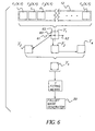
- a pixel value 65 of a first avenge frame F 1 at a specific location is computed by averaging together the pixel values of all frames at that same location (for example the specific location may the upper right hand corner 60, see Fig. 6).
- the first average frame F 1 is forced to have symmetry about a vertical axis 61 and a horizontal axis 62 in the following manner.
- Three more images are generated from the first average frame F 1 by reflecting about the horizontal axis 61, the vertical axis 62, and both the horizontal and the vertical axes 62 and 61 respectively.
- a second average frame F 2 which is the first avenge frame F 1 flipped about the horizontal axis 61
- a third avenge frame F 3 which is the first average frame F 1 flipped about the horizontal axis 61
- a fourth average frame F 4 which is the second average frame F 2 flipped about the vertical axis 62.
- the four average frames F 1 , F 2 , F 3 and F 4 are then averaged together in order to generate a symmetric average frame F S .
- a cos 4 surface is then fit to the symmetric average frame F S .
- many cos 4 falloff surfaces are generated by varying the parameter f and the offset m in Equation 5.
- fit(x, y ) is comparable to equation 1.
- the result of the best fit here provides a value for f , the light falloff correction parameter.
- fit(x,y) 1000 log 10 cos 4 tan -1 d f + m
- the fit(x,y) which produces the minimum least squared error with reference to the symmetric average frame is the optimal fit.
- the value of the parameter f used to generate the falloff compensation function fcf is then set to the f which was used to produce the optimal fit.
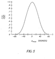
- Fig. 7 is a graphical representation of intensity distribution (in 1000 x log E) in an average frame.
- sub-samples of 64 times 64 pixels are formed from the digital image, which comprises for example 1024 times 1536 pixel elements.
- the sub-sampling one ends up with a digital image comprising 16 times 24 image blocks for the average frame. It is clear for a skilled person that other sizes of the sub-samples may be chosen and consequently their selection is obvious.
- the number of image blocks governs the time necessary for any calculation. So the fewer the blocks or pixels of an image to be considered the faster the result for the required parameter for the falloff compensation function.
- Fig. 8 According to the above sub-sampling the intensity distribution in the symmetric average frame F S is shown in Fig. 8.
- the determination of the average image frame F S is done with the same size of sub-samples as used in Fig. 7.
- the average image frame F S is fitted to a cos 4 surface in order to provide a fit-parameter f sub .
- a graphic representation of the average image frame F S fitted to the cos 4 surface is shown in Fig. 9.
- the graphical representation of a light falloff compensation mask is shown in Fig. 10. This is a three dimensional representation of the compensation values, which are applied to associated pixel values of each image frame on said film roll 12, from which the average image frame F S is generated form.
- Fig. 11 is a representation of an image before the compensation for light falloff has been carried out.
- the compensated image (Fig. 12) shows a major improvement in image quality.
- the image (Fig. 11) before the compensation is darker at its corners as in its center. This image defect is caused by the discussed light falloff.
- the compensation for light falloff furnishes an image, which is free from the light falloff defect.
- the image (Fig. 12) shows an even exposure.
- the result of compensation as shown in Fig. 12 is done with the above method of generating an avenge image frame F S from a single film roll.
- the flash falloff compensation function, ffcf is also described as a mathematical function of location in the image.
- the flash falloff compensation function ffcf is of greater magnitude than the lens falloff compensation function lfcf (in other words, generally ffcf(0 , 0) > lfcf(0 , 0).
- Flash falloff generally may not be radially symmetric with respect to the center of the image.
- the flash falloff compensation function ffcf(x,y) 0 for pixel values pij. This may be accomplished by selecting a large value (such as 1000 x d max ) for f2 .
- a much lower flash correction parameter f2 is appropriate. For instance, an image with harsh flash falloff may benefit greatly from a flash correction parameter f2 of 1.5 ⁇ d max .
- d max is 1.414
- an approximate value of f2 may be 2.1.
- Another possibility for obtaining a value for the flash correction parameter f2 is that an operator simply adjusts a slider of a graphical user interface which applies a falloff compensation mask generated with light falloff compensation function with any number of choices for f2 . The operator adjusts the slider until he is pleased with the results. The resulting value for the f2 is preserved and input to the lens falloff function generator 30.
- a specific function for the flash falloff characteristics may be specified at the time of manufacture of the flash unit. This information, along with the information of whether of not the flash was used on a specific frame, may be used to construct a flash falloff compensation mask. Information of tat kind may be provided on some recording areas on the photographic film. The printer reads the information and utilizes it for the calculation of the flash falloff correction parameter f2 .
- a further possibility to calculate the flash falloff correction parameter f2 is determined from an analysis of the pixel values of the images captured with the same imaging device. All of the images are captured with the same flash fire conditions. In many image capture systems, the scene flash fire condition may be recorded with the scene. In a simple case, the Advanced Photo System records with each scene whether the flash was fired or not. The scenes in a common order where the flash was fired may be used to generate a symmetric average frame, as previously described. A cos 4 surface may be optimally fit to the symmetric average frame by minimizing the squared error between the symmetric average frame and the cos 4 surface. The value of f t that generates the optimal fit may be used as the flash correction parameter f2 in the flash falloff compensation function ffcf .
- the image data metric may be linearly related to exposure of the scene.
- the calculation of the light falloff compensation function fcf is shown in equation 10.
- ⁇ and ⁇ 2 remain the same as described above, and the selection or determination of ⁇ and ⁇ 2 also remain identical to the above methods.
- the light falloff compensation function, fcf(x,y) may be equal to only the lens falloff compensation function, lfcf(x,y) .
- the value of f 2 is decreased.
- the combination of lens and flash falloff is modeled simply as a more severe case of lens falloff than is actually the case.
- the method for compensating digital images may encompass additional steps to provide an output of an image, which is compensated for light falloff.
- the inventive method comprises several steps. At first, providing a plurality of pixel values, which are generated from at least one conventional photographic frame or digital image. Also a light falloff compensation function fcf is provided.
- the light falloff compensation function fcf is constituted by a two-dimensional function (see Equation 1 or 5). The equations include both an unknown parameter f.
- the specification above shows numerous possibilities for generating, determining or choosing a value for the so-called light falloff correction parameter. According to the selection of the light falloff correction parameter and the light falloff compensation function fcf , a compensation value may be generated for each pixel value of the original image.
- a compensation for non-linearities in the response of the imaging device is carried out.
- the correction for non-linearities in the response of the imaging device may be necessary.
- a method of correcting for the non-linearities in the response of photographic film may be implemented if the digital image is of film origin. Such a method is described in U.S. Patent 5,134,573 by Goodwin. Such a method is performed prior to the application of the light falloff compensation mask..
- a further step of the inventive method is to estimate balance and tonal modifications, which are required by a digital image.
- the application of the light falloff compensation mask is performed prior to estimating the balance of the digital image.
- This balance could for instance be obtained with an automatic exposure determination algorithm (such as are used in high speed optical printers or in a Photo-CD scanner, see for example U.S. Patent 4,945,406).
- the desired level of exposure is determined from an image which been modified by the falloff correction.
- the application of the light falloff compensation mask is performed prior to estimating the tonal modifications required by the digital image.
- the contrast of the image may be estimated by an automatic algorithm.
- the contrast of the digital image may likewise be modified to a preferred level of contrast.
Landscapes
- Engineering & Computer Science (AREA)
- Multimedia (AREA)
- Signal Processing (AREA)
- Studio Devices (AREA)
- Control Of Exposure In Printing And Copying (AREA)
- Image Processing (AREA)
- Facsimile Image Signal Circuits (AREA)
- Stroboscope Apparatuses (AREA)
Applications Claiming Priority (2)
| Application Number | Priority Date | Filing Date | Title |
|---|---|---|---|
| US09/293,197 US6670988B1 (en) | 1999-04-16 | 1999-04-16 | Method for compensating digital images for light falloff and an apparatus therefor |
| US293197 | 1999-04-16 |
Publications (2)
| Publication Number | Publication Date |
|---|---|
| EP1045573A2 true EP1045573A2 (de) | 2000-10-18 |
| EP1045573A3 EP1045573A3 (de) | 2001-12-19 |
Family
ID=23128105
Family Applications (1)
| Application Number | Title | Priority Date | Filing Date |
|---|---|---|---|
| EP00201248A Withdrawn EP1045573A3 (de) | 1999-04-16 | 2000-04-05 | Verfahren und Vorrichtung zur Kompensation von digitalen Bildern seitens Lichtschwächung |
Country Status (3)
| Country | Link |
|---|---|
| US (1) | US6670988B1 (de) |
| EP (1) | EP1045573A3 (de) |
| JP (1) | JP2000358157A (de) |
Cited By (8)
| Publication number | Priority date | Publication date | Assignee | Title |
|---|---|---|---|---|
| EP1292128A2 (de) | 2001-09-06 | 2003-03-12 | Ricoh Company, Ltd. | Vorichtung und Verfahren zur Bildaufnahme |
| EP1379075A1 (de) * | 2002-07-05 | 2004-01-07 | Noritsu Koki Co., Ltd. | Verfahren und Vorrichtung zur Korrektur von Bilddaten, die von einem Originalbild erhalten wurden, das von einem Randabfall des Lichtes beeinflusst wird |
| EP1251461A3 (de) * | 2001-04-04 | 2006-05-24 | Eastman Kodak Company | Verfahren zum Kompensieren des Lichtabfalls eines digitalen Bildes bei minimaler Änderung des Lichtgleichgewichts |
| EP1950979A1 (de) | 2007-01-25 | 2008-07-30 | Research In Motion Limited | Elektronisches Handgerät und Kamera mit Blitzausgleich der Bilder und dazugehöriges Verfahren |
| EP1359745B1 (de) * | 2001-02-07 | 2008-12-24 | Sony Corporation | Schirmkorrekturverfahren und abbildungseinrichtung |
| US7702235B2 (en) | 2007-01-25 | 2010-04-20 | Research In Motion Limited | Handheld electronic device and camera providing flash compensation of images, and associated method |
| CN101341733B (zh) * | 2005-12-23 | 2011-04-20 | 微软公司 | 单图像晕映纠正 |
| US10005682B1 (en) | 2009-10-02 | 2018-06-26 | Tersano Inc. | Holding tank-less water ozonating system |
Families Citing this family (13)
| Publication number | Priority date | Publication date | Assignee | Title |
|---|---|---|---|---|
| US6941027B1 (en) * | 2000-07-27 | 2005-09-06 | Eastman Kodak Company | Method of and system for automatically determining a level of light falloff in an image |
| US20030020946A1 (en) * | 2001-07-26 | 2003-01-30 | O'hara Sean M. | Printer capable of directly printing using negative or positive film source |
| JP4096828B2 (ja) * | 2003-07-15 | 2008-06-04 | セイコーエプソン株式会社 | 画像処理装置 |
| US20070081224A1 (en) * | 2005-10-07 | 2007-04-12 | Robinson M D | Joint optics and image processing adjustment of electro-optic imaging systems |
| US20070211154A1 (en) * | 2006-03-13 | 2007-09-13 | Hesham Mahmoud | Lens vignetting correction algorithm in digital cameras |
| US8259179B2 (en) * | 2006-05-15 | 2012-09-04 | Csr Technology Inc. | Compensating for non-uniform illumination of object fields captured by a camera |
| CN100583956C (zh) * | 2007-06-25 | 2010-01-20 | 鸿富锦精密工业(深圳)有限公司 | 成像设备及其镜头光线强度衰减补偿方法 |
| US8274583B2 (en) * | 2009-06-05 | 2012-09-25 | Apple Inc. | Radially-based chroma noise reduction for cameras |
| US8571343B2 (en) | 2011-03-01 | 2013-10-29 | Sharp Laboratories Of America, Inc. | Methods and systems for document-image correction |
| US20130016186A1 (en) * | 2011-07-13 | 2013-01-17 | Qualcomm Incorporated | Method and apparatus for calibrating an imaging device |
| JP6215894B2 (ja) * | 2015-10-22 | 2017-10-18 | 株式会社Screenホールディングス | 画像処理方法およびシェーディング基準データ作成方法 |
| JP7134666B2 (ja) * | 2018-03-28 | 2022-09-12 | キヤノン株式会社 | 画像処理装置、画像処理方法、およびプログラム |
| CN116206573B (zh) * | 2021-11-30 | 2024-12-06 | 广州视源电子科技股份有限公司 | 一种光强值确定方法、装置、设备及存储介质 |
Family Cites Families (19)
| Publication number | Priority date | Publication date | Assignee | Title |
|---|---|---|---|---|
| US5523553A (en) * | 1983-10-19 | 1996-06-04 | Nikon Corporation | Camera with focus detecting device for removing vignetting effects |
| US4583186A (en) * | 1984-03-26 | 1986-04-15 | Bremson Data Systems | Computerized video imaging system |
| JPS61275625A (ja) * | 1985-05-31 | 1986-12-05 | Fuji Photo Film Co Ltd | カラ−写真画像情報の較正方法 |
| US4734783A (en) * | 1985-08-26 | 1988-03-29 | Fuji Photo Film Co., Ltd. | Shading elimination device for image read-out apparatus |
| JPH0756530B2 (ja) * | 1986-03-31 | 1995-06-14 | 株式会社ニコン | 撮影レンズ鏡筒およびカメラ |
| US4945406A (en) | 1988-11-07 | 1990-07-31 | Eastman Kodak Company | Apparatus and accompanying methods for achieving automatic color balancing in a film to video transfer system |
| US4979042A (en) * | 1989-05-30 | 1990-12-18 | Eastman Kodak Company | Apparatus for correcting shading effects in video images |
| EP0460193B1 (de) | 1989-12-26 | 1995-07-19 | Eastman Kodak Company | Verfahren zur ausdehnung des linearbereichs der aufgenommenen bilder eines films |
| JPH04138770A (ja) * | 1990-09-28 | 1992-05-13 | Minolta Camera Co Ltd | シェーディング補正方法 |
| AU2510792A (en) | 1991-08-23 | 1993-03-16 | United Parcel Service Of America, Inc. | Method and apparatus for compensation for non-uniform illumination |
| JP3191354B2 (ja) * | 1991-11-15 | 2001-07-23 | ソニー株式会社 | シェーディング補正回路 |
| US5303056A (en) * | 1992-09-14 | 1994-04-12 | Eastman Kodak Company | Dynamic gain correction for CRT printing |
| US5461440A (en) | 1993-02-10 | 1995-10-24 | Olympus Optical Co., Ltd. | Photographing image correction system |
| DK0959425T3 (da) * | 1994-10-25 | 2005-01-03 | United Parcel Service Inc | Automatisk elektronisk kamera til optagelse af billeder af etiketter |
| US5822453A (en) | 1996-12-10 | 1998-10-13 | Eastman Kodak Company | Method for estimating and adjusting digital image contrast |
| JP3351704B2 (ja) * | 1997-04-09 | 2002-12-03 | ペンタックス株式会社 | 画像信号補正装置 |
| DE19855885A1 (de) * | 1997-12-04 | 1999-08-05 | Fuji Photo Film Co Ltd | Bildverarbeitungsverfahren und -vorrichtung |
| DE19913311A1 (de) * | 1998-03-25 | 1999-09-30 | Fuji Photo Film Co Ltd | Bildverarbeitungsvorrichtung |
| US6339466B1 (en) * | 1998-06-08 | 2002-01-15 | Fuji Photo Film Co., Ltd. | Image processing apparatus |
-
1999
- 1999-04-16 US US09/293,197 patent/US6670988B1/en not_active Expired - Lifetime
-
2000
- 2000-04-05 EP EP00201248A patent/EP1045573A3/de not_active Withdrawn
- 2000-04-13 JP JP2000111743A patent/JP2000358157A/ja active Pending
Cited By (13)
| Publication number | Priority date | Publication date | Assignee | Title |
|---|---|---|---|---|
| EP1359745B1 (de) * | 2001-02-07 | 2008-12-24 | Sony Corporation | Schirmkorrekturverfahren und abbildungseinrichtung |
| EP1251461A3 (de) * | 2001-04-04 | 2006-05-24 | Eastman Kodak Company | Verfahren zum Kompensieren des Lichtabfalls eines digitalen Bildes bei minimaler Änderung des Lichtgleichgewichts |
| EP1292128B1 (de) * | 2001-09-06 | 2011-06-01 | Ricoh Company, Ltd. | Vorrichtung und Verfahren zur Bildaufnahme |
| EP1292128A2 (de) | 2001-09-06 | 2003-03-12 | Ricoh Company, Ltd. | Vorichtung und Verfahren zur Bildaufnahme |
| EP1379075A1 (de) * | 2002-07-05 | 2004-01-07 | Noritsu Koki Co., Ltd. | Verfahren und Vorrichtung zur Korrektur von Bilddaten, die von einem Originalbild erhalten wurden, das von einem Randabfall des Lichtes beeinflusst wird |
| US7268917B2 (en) | 2002-07-05 | 2007-09-11 | Noritsu Koki Co., Ltd. | Image correction processing method and apparatus for correcting image data obtained from original image affected by peripheral light-off |
| CN101341733B (zh) * | 2005-12-23 | 2011-04-20 | 微软公司 | 单图像晕映纠正 |
| US7702235B2 (en) | 2007-01-25 | 2010-04-20 | Research In Motion Limited | Handheld electronic device and camera providing flash compensation of images, and associated method |
| EP1950979A1 (de) | 2007-01-25 | 2008-07-30 | Research In Motion Limited | Elektronisches Handgerät und Kamera mit Blitzausgleich der Bilder und dazugehöriges Verfahren |
| US8009978B2 (en) | 2007-01-25 | 2011-08-30 | Research In Motion Limited | Handheld electronic device and camera providing flash compensation of images, and associated method |
| US8306412B2 (en) | 2007-01-25 | 2012-11-06 | Research In Motion Limited | Handheld electronic device and camera providing flash compensation of images, and associated method |
| US8693862B2 (en) | 2007-01-25 | 2014-04-08 | Blackberry Limited | Handheld electronic device and camera providing flash compensation of images, and associated method |
| US10005682B1 (en) | 2009-10-02 | 2018-06-26 | Tersano Inc. | Holding tank-less water ozonating system |
Also Published As
| Publication number | Publication date |
|---|---|
| EP1045573A3 (de) | 2001-12-19 |
| JP2000358157A (ja) | 2000-12-26 |
| US6670988B1 (en) | 2003-12-30 |
Similar Documents
| Publication | Publication Date | Title |
|---|---|---|
| US6670988B1 (en) | Method for compensating digital images for light falloff and an apparatus therefor | |
| US6628329B1 (en) | Correction of position dependent blur in a digital image | |
| US7433089B2 (en) | Image processor | |
| US7920172B2 (en) | Method of controlling an action, such as a sharpness modification, using a colour digital image | |
| US7496287B2 (en) | Image processor and image processing program | |
| JP2000050076A (ja) | シ―ンバランス、コントラスト正規化及び鮮明化のデジタル画像処理を含むデジタル写真仕上げシステム | |
| US6313902B1 (en) | Image processing method and apparatus | |
| JP4176369B2 (ja) | 光バランスの変化を最小としつつディジタル画像を光フォールオフについて補償する方法 | |
| JP3998369B2 (ja) | 画像処理方法および画像処理装置 | |
| US20040212680A1 (en) | Device for determining a location-dependent intensity profile and color profile and/or sharpness profile of optical lens system | |
| JP3549413B2 (ja) | 画像処理方法および画像処理装置 | |
| JPH0654195A (ja) | マイクロフィルム画質を改良させる画像スキャナシステム及び方法 | |
| JP2000050078A (ja) | シ―ンバランス及び鮮明化のデジタル画像処理を含むデジタル写真仕上げシステム | |
| US6577378B1 (en) | System and method for light falloff compensation in an optical system | |
| JP3783817B2 (ja) | 画像処理方法および画像処理装置 | |
| JP3576809B2 (ja) | 画像処理装置 | |
| JP2003189169A (ja) | 画像処理装置 | |
| US6498638B1 (en) | Optimization apparatus for photographic image data | |
| JP2001086332A (ja) | 画像処理装置 | |
| JP3386373B2 (ja) | 撮影画像の類似性判定方法およびこれを用いた画像処理方法および画像処理装置 | |
| JP3653661B2 (ja) | 画像処理装置 | |
| JP3576812B2 (ja) | 画像処理装置及び画像処理方法 | |
| JP3625370B2 (ja) | 画像処理方法および画像処理装置 | |
| US6941027B1 (en) | Method of and system for automatically determining a level of light falloff in an image | |
| JP4731695B2 (ja) | 多点測距カメラを利用した画像処理システム |
Legal Events
| Date | Code | Title | Description |
|---|---|---|---|
| PUAI | Public reference made under article 153(3) epc to a published international application that has entered the european phase |
Free format text: ORIGINAL CODE: 0009012 |
|
| AK | Designated contracting states |
Kind code of ref document: A2 Designated state(s): AT BE CH CY DE DK ES FI FR GB GR IE IT LI LU MC NL PT SE Kind code of ref document: A2 Designated state(s): CH DE FR GB LI |
|
| AX | Request for extension of the european patent |
Free format text: AL;LT;LV;MK;RO;SI |
|
| PUAL | Search report despatched |
Free format text: ORIGINAL CODE: 0009013 |
|
| AK | Designated contracting states |
Kind code of ref document: A3 Designated state(s): AT BE CH CY DE DK ES FI FR GB GR IE IT LI LU MC NL PT SE |
|
| AX | Request for extension of the european patent |
Free format text: AL;LT;LV;MK;RO;SI |
|
| 17P | Request for examination filed |
Effective date: 20020531 |
|
| AKX | Designation fees paid |
Free format text: CH DE FR GB LI |
|
| STAA | Information on the status of an ep patent application or granted ep patent |
Free format text: STATUS: THE APPLICATION IS DEEMED TO BE WITHDRAWN |
|
| 18D | Application deemed to be withdrawn |
Effective date: 20061114 |