EP1288476B1 - Gehäusedeckel mit akustisch entkoppeltem Anschlag - Google Patents
Gehäusedeckel mit akustisch entkoppeltem Anschlag Download PDFInfo
- Publication number
- EP1288476B1 EP1288476B1 EP02016595A EP02016595A EP1288476B1 EP 1288476 B1 EP1288476 B1 EP 1288476B1 EP 02016595 A EP02016595 A EP 02016595A EP 02016595 A EP02016595 A EP 02016595A EP 1288476 B1 EP1288476 B1 EP 1288476B1
- Authority
- EP
- European Patent Office
- Prior art keywords
- extension
- housing cover
- engine block
- cover
- seal
- Prior art date
- Legal status (The legal status is an assumption and is not a legal conclusion. Google has not performed a legal analysis and makes no representation as to the accuracy of the status listed.)
- Expired - Lifetime
Links
- 238000007789 sealing Methods 0.000 claims abstract description 39
- 229920001971 elastomer Polymers 0.000 claims abstract description 3
- 239000000806 elastomer Substances 0.000 claims abstract description 3
- 230000002093 peripheral effect Effects 0.000 claims abstract 3
- 238000002485 combustion reaction Methods 0.000 claims description 5
- 239000000463 material Substances 0.000 description 5
- 238000006073 displacement reaction Methods 0.000 description 4
- 239000004033 plastic Substances 0.000 description 3
- 229920003023 plastic Polymers 0.000 description 3
- 238000010276 construction Methods 0.000 description 2
- 238000011161 development Methods 0.000 description 2
- 230000018109 developmental process Effects 0.000 description 2
- 238000000034 method Methods 0.000 description 2
- 230000008092 positive effect Effects 0.000 description 2
- 239000003566 sealing material Substances 0.000 description 2
- 230000006978 adaptation Effects 0.000 description 1
- 230000002238 attenuated effect Effects 0.000 description 1
- 230000001419 dependent effect Effects 0.000 description 1
- 230000000694 effects Effects 0.000 description 1
- 238000004519 manufacturing process Methods 0.000 description 1
- 229910052751 metal Inorganic materials 0.000 description 1
- 239000002184 metal Substances 0.000 description 1
- 150000002739 metals Chemical class 0.000 description 1
Images
Classifications
-
- F—MECHANICAL ENGINEERING; LIGHTING; HEATING; WEAPONS; BLASTING
- F02—COMBUSTION ENGINES; HOT-GAS OR COMBUSTION-PRODUCT ENGINE PLANTS
- F02B—INTERNAL-COMBUSTION PISTON ENGINES; COMBUSTION ENGINES IN GENERAL
- F02B77/00—Component parts, details or accessories, not otherwise provided for
- F02B77/11—Thermal or acoustic insulation
- F02B77/13—Acoustic insulation
-
- F—MECHANICAL ENGINEERING; LIGHTING; HEATING; WEAPONS; BLASTING
- F02—COMBUSTION ENGINES; HOT-GAS OR COMBUSTION-PRODUCT ENGINE PLANTS
- F02F—CYLINDERS, PISTONS OR CASINGS, FOR COMBUSTION ENGINES; ARRANGEMENTS OF SEALINGS IN COMBUSTION ENGINES
- F02F11/00—Arrangements of sealings in combustion engines
- F02F11/002—Arrangements of sealings in combustion engines involving cylinder heads
-
- F—MECHANICAL ENGINEERING; LIGHTING; HEATING; WEAPONS; BLASTING
- F02—COMBUSTION ENGINES; HOT-GAS OR COMBUSTION-PRODUCT ENGINE PLANTS
- F02F—CYLINDERS, PISTONS OR CASINGS, FOR COMBUSTION ENGINES; ARRANGEMENTS OF SEALINGS IN COMBUSTION ENGINES
- F02F7/00—Casings, e.g. crankcases
- F02F7/006—Camshaft or pushrod housings
Definitions
- the invention describes a housing cover for an internal combustion engine, in particular cylinder head covers or oil pans, for releasable, liquid-tight fastening to the engine block, with an elastomeric sealing profile at the edge of the housing cover being provided on the edge of the housing cover inside a directed towards the engine block axial extension which axially over a sealing surface protrudes and that at least between the axial extension and the engine block, a seal is arranged, wherein the seal is designed as a separate part and connected to the extension
- the attachment parts attached to the component are primarily housing covers, such as cylinder head covers or oil covers, of internal combustion engines.
- housing covers such as cylinder head covers or oil covers
- the bearing surface of the sealing profile on the engine block is referred to as a sealing surface.
- a disadvantage of the use of elastomers is that they are subjected to a more or less large relaxation. The relaxation is counteracted inter alia with combined decoupling devices.
- a vibration decoupling device for a housing cover, in which in addition to a fferenentkopplung a decoupling element is arranged as a sealing profile in the lid edge.
- the sealing profile serves to seal an interior space provided within the housing cover and for vibration decoupling between the housing cover and the engine block and the screw decoupling inter alia to the relaxation and an associated risk of leakage.
- housing cover made of plastic, it is because of the generally low rigidity in contrast to metals the risk that it comes to a shift, ie walking due to relaxation or deformation of the lid edge of the housing cover between the mounting screws, the danger Of course, the displacement of metallic housing covers also exists.
- a relaxation of the sealing profile is counteracted by the screw decoupling, a safeguard against the displacement of the lid edge over the sealing surface is not given.
- a housing cover as a valve cover for a cylinder head of an internal combustion engine, in which by the use of a metallic spring body, the biasing force can be adjusted to the seal.
- the sealing profile is pressed at the edge of the cover, during tightening with a certain force on the engine block.
- the metallic spring body By using the metallic spring body, the valve cover is able to follow the relaxation of the sealing profile.
- a disadvantage of this type of construction of a housing cover is that although the force on the seal can be kept relatively constant, a sliding movement of the lid edges on the sealing surface but nothing prevents it. Sliding movements of the lid edge can z. B. caused by fatigue of the housing cover material or excessive tightening torques of the cover screws. This is especially true if the housing cover materials do not have sufficient strength, the components can not be designed sufficiently rigid or there is an unfavorable Verschraubungsanssen.
- the seal may be damaged as a result of the sliding movement or the sealing forces on the elastomeric sealing material are no longer sufficient to prevent leakage.
- the JP 06 221441 A discloses a generic housing cover. The arranged at the edge of the seal axial extension prevents a radial displacement of the seal, however, is generated in the axial direction no sufficient anti-displacement.
- the object of the invention is thus to develop a housing cover which counteracts the sliding movements of the lid edge and at the same time includes an acoustic decoupling.
- the extension of the housing cover By means of the inventive axial extension of the housing cover sliding movements of the lid edge are no longer possible. Rather, it can be done a targeted positioning of the lid on the sealing surface of the engine block.
- This targeted positioning offers the advantage that the sealing surface on the engine block can be adapted exactly to the shape of the elastomeric sealing profile material. This in turn leads to material savings on the sealing surface, which in turn has a positive effect on the weight of the engine.
- Another advantage is that the extension of the housing cover a targeted and defined introduction of force in the elastomeric sealing material is possible, it follows that the voltages occurring can be reliably calculated and adjusted.
- the extension supports the assembly, so it can during assembly as a joining aid and during the attachment for positioning of the Serving housing cover.
- extension according to the invention is designed so that it already clamps the housing cover during joining so overhead mounting, as can occur, for example, on oil pans, can be substantially facilitated.
- the extension on the edge of the lid is arranged circumferentially on the edge of the lid in a patented embodiment. Depending on the application and structural conditions, the extension on the edge of the lid may also be only partially formed.
- the partial training offers the advantage of less weight and the circumferential training the advantage of safer leadership.
- the extension projects beyond the sealing surface in the direction of the engine block and according to the invention forms an undercut relative to the engine block. According to the invention, partial as well as circumferential undercuts are possible.
- any shape of the undercut is conceivable, it should be noted that the housing cover is detachable and must be designed in such a way that an expansion of the housing cover without damaging the extension must be possible.
- curves at the ends of the extension serve to facilitate the joining of the housing cover.
- the slope extends from the inside of the housing cover in the direction of the outside.
- the undercut in the form of a slope offers the advantage that when the cover edge is displaced, the housing cover is pulled in the direction of the sealing surface, at the same time increasing the sealing force. Using this advantage, the effect between sliding movement and construction of the sealing forces can be specifically influenced.
- the undercut in the form of a slope offers the possibility to bring a bias to the sealing profiles of the housing cover, so that a very accurate positioning takes place already in the joining phase, which in turn can have a positive effect on automated fastening method.
- the housing cover may be made of any materials, but is preferably made according to the invention of a plastic. The relaxation occurring in plastics and the associated sliding movements of the sealing profiles on the sealing surface are now avoided by the extension according to the invention.
- Positive locking means for example, that the seal is U-shaped, wherein the two legs are pushed over the axially lower end of the extension. By adjusting the spacing of the legs, the strength of the seat of the seal can then be adjusted.
- the housing cover By placing a seal between the extension and the engine block, the housing cover can not come into contact with the engine block when vibrations occur during operation of the engine.
- the housing cover is acoustically decoupled.
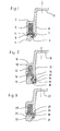
- FIG. 1 shows the section through a housing cover 1.
- the housing cover 1 has a lid edge 2 in which the elastomeric sealing profile 3 is arranged, wherein the elastomeric sealing profile 3 rests on the sealing surface 4 of the engine block 5.
- the housing cover 1 On the inside of the cover edge 6, the housing cover 1 has an extension 7, which projects beyond the sealing surface 4.
- the extension 7 is formed in such a way that with respect to the engine block 5, an undercut 8 is formed.
- the undercut 8 is shown in the form of a slope.
- the sealing profile 3 is formed in one piece and extends from the sealing surface 4 to the end 10 of the extension. 7
- a section through a housing cover 10 with a lid edge 11, an elastomeric sealing profile 12 and a motor block 13 is shown in FIG 2.
- the extension 14 on the lid edge 11 protrudes beyond the sealing surface 15 and has a slope 16 which from the inside 17 of the housing cover 10 to Outside 18 is directed, wherein on the extension 14, a further slope 19 is arranged, which is formed opposite in direction of the first slope 16, so that the further slope 19 can serve as a joining aid.
- a seal 20 is arranged, which is positively connected 21 with the extension 14.
- FIG. 3 shows the section through a housing cover 22 in which the engine block 23 of the extension 24 has been adapted correspondingly in terms of design. In this case, a chamfer 25 is provided on the engine block 23, which facilitates the joining of the housing cover 22.
- the chamfer 25 has a slope 26 in the direction of the housing cover 22 for joining and a bevel 27 in the direction of the engine block 23 for disassembly of the housing cover 22.
- the chamfer 25 can also serve to limit the deformation of the elastomeric seal 28 and in the direction of the elastomeric seal 28 may be designed accordingly (eg round).
- the extension has engine block side a vulcanized seal 29, which decouples the housing cover 22 against the engine block 23 acoustically.
Landscapes
- Engineering & Computer Science (AREA)
- Chemical & Material Sciences (AREA)
- Combustion & Propulsion (AREA)
- Mechanical Engineering (AREA)
- General Engineering & Computer Science (AREA)
- Physics & Mathematics (AREA)
- Acoustics & Sound (AREA)
- Cylinder Crankcases Of Internal Combustion Engines (AREA)
- Vehicle Step Arrangements And Article Storage (AREA)
- Lubrication Details And Ventilation Of Internal Combustion Engines (AREA)
- Gasket Seals (AREA)
Description
- Die Erfindung beschreibt einen Gehäusedeckel für eine Verbrennungskraftmaschine, insbesondere Zylinderkopfhauben oder Ölwannen, zum lösbaren, flüssigkeitsdichten Befestigen am Motorblock, mit einem elastomeren Dichtungsprofil am Rand des Gehäusedeckels wobei am Rand des Gehäusedeckel innenseitig eine in Richtung des Motorblocks gerichtete axiale Verlängerung vorgesehen ist, die axial über eine Dichtfläche hinausragt und dass mindestens zwischen der axialen Verlängerung und dem Motorblock eine Dichtung angeordnet ist, wobei die Dichtung als separates Teil ausgeführt und mit der Verlängerung verbunden ist
- Bei Motoren, insbesondere bei Verbrennungskraftmaschinen, läßt es sich nicht vermeiden, dass ein Bauteil, wie beispielsweise der Motorblock, während des Betriebs des Motors schwingt. Diese Schwingungen können zu einer unangenehmen Geräuschentwicklung führen. Damit die Schwingungen des Bauteils nicht bzw. nur gedämpft auf die an das Bauteil angebauten Anbauteile übertragen werden, ist es allgemein üblich elastomere Dichtungsprofile in die Anbauteile zu integrieren, die dann für eine akustische Entkopplung der Anbauteile sorgen. Durch diese Maßnahme kann die Geräuschentwicklung häufig beträchtlich reduziert werden. Bei den an das Bauteil angebrachten Anbauteilen handelt es sich vornehmlich um Gehäusedeckel, wie beispielsweise Zylinderkopfhauben oder Öldeckel, von Verbrennungskraftmaschinen. Bei dieser akustischen Entkopplung des Gehäusedeckels wird ein elastomeres Dichtungsprofil zwischen dem Gehäusedeckel und dem Motorblock positioniert. Die Auflagefläche des Dichtungsprofils auf dem Motorblock wird dabei als Dichtfläche bezeichnet.
Nachteilig beim Einsatz von Elastomeren ist, dass diese einer mehr oder weniger großen Relaxation unterworfen sind. Der Relaxation wird unter anderem mit kombinierten Entkopplungseinrichtungen entgegengearbeitet. - So wird in der
US 5,255,647 eine Schwingungsentkopplungseinrichtung für einen Gehäusedeckel vorgeschlagen, bei der neben einer Schraubenentkopplung ein Entkopplungselement als Dichtungsprofil im Deckelrand angeordnet ist. Dabei dient das Dichtungsprofil zur Abdichtung eines innerhalb des Gehäusedeckels vorgesehenen Innenraums und zur schwingungsmäßigen Entkopplung zwischen dem Gehäusedeckel und dem Motorblock und die Schraubenentkopplung unter anderem dazu der Relaxation und einer damit verbundenen Gefahr von Undichtigkeiten entgegenzutreten.
Werden solche Gehäusedeckel aus Kunststoff gefertigt, so besteht wegen der im allgeimein geringen Steifigkeit im Gegensatz zu Metallen die Gefahr, dass es zu einem Verschieben, d.h. zu einem Wandern in Folge von Relaxation oder Verformung des Deckelrands des Gehäusedeckels zwischen den Befestigungsschrauben kommt, wobei die Gefahr des Verschiebens bei metallischen Gehäusedeckeln natürlich auch besteht. So wird durch die Schraubenentkopplung zwar einer Relaxation des Dichtungsprofils entgegengewirkt, eine Sicherung gegen das Verschieben des Deckelrands über die Dichtfläche hinweg ist aber nicht gegeben. - Um der Relaxation des Dichtungsprofils entgegenzuwirken wird in der
EP 0 664 388 A1 ein Gehäusedeckel als Ventildeckel für einen Zylinderkopf eines Verbrennungsmotors vorgeschlagen, in dem durch den Einsatz eines metallischen Federkörpers die Vorspannkraft auf die Dichtung eingestellt werden kann. Hierbei wird das Dichtungsprofil am Deckelrand, während des Anziehens mit einer bestimmten Kraft am Motorblock verpresst. Durch den Einsatz des metallischen Federkörpers ist der Ventildeckel in der Lage der Relaxation des Dichtungsprofils zu folgen.
Nachteilig bei dieser Art des Aufbaus eines Gehäusedeckels ist, dass zwar die Kraft auf die Dichtung relativ konstant gehalten werden kann, einer Schiebebewegung der Deckelränder über die Dichtfläche aber nichts entgegensteht. Schiebebewegungen des Deckelrandes können z. B. durch Ermüdung des Gehäusedeckelwerkstoffs oder durch überhöhte Anzugsmomente der Deckelschrauben entstehen. Dies gilt insbesondere wenn die Gehäusedeckelwerkstoffe keine ausreichende Festigkeit besitzen, die Bauteile nicht ausreichend steif konstruiert werden können oder eine ungünstige Verschraubungsanordnung vorliegt. - Die Dichtung kann infolge der Schiebebewegung schaden nehmen oder die Dichtkräfte auf den elastomeren Dichtungswerkstoff sind nicht mehr ausreichend um eine Leckage zu vermeiden.
- Die
JP 06 221441 A - Aufgabe der Erfindung ist es somit einen Gehäusedeckel zu entwickeln der den Schiebebewegungen des Deckelrandes entgegenwirkt und der gleichzeitig eine akustische Entkopplung beinhaltet.
- Diese Aufgabe wird erfindungsgemäß durch den kennzeichnenden Teil des Patentanspruchs 1 gelöst, vorteilhafte Weiterbildungen der Erfindung sind in den Unteransprüchen dokumentiert.
- Mittels der erfindungsgemäßen, axialen Verlängerung des Gehäusedeckels sind Schiebebewegungen des Deckelrandes nun nicht mehr möglich. Es kann vielmehr eine gezielte Positionierung des Deckels auf der Dichtfläche des Motorblocks erfolgen. Diese gezielte Positionierung bietet den Vorteil, das die Dichtfläche am Motorblock der Form des elastomeren Dichtungsprofilwerkstoffs exakt angepasst werden kann. Dies führt wiederum zu Materialersparnis an der Dichtfläche, was sich wiederum positiv auf das Gewicht des Motors auswirkt.
Ein weiterer Vorteil ist, dass durch die Verlängerung des Gehäusedeckels eine gezielte und definierte Krafteinleitung in den elastomeren Dichtungswerkstoff möglich wird, hieraus ergibt sich, dass die auftretenden Spannungen zuverlässiger berechnet und eingestellt werden können.
Neben diesen Vorteilen unterstützt die Verlängerung die Montage, so kann sie während des Zusammenbaus als Fügehilfe und während der Befestigung zur Positionierung des Gehäusedeckels dienen. Wird die Verlängerung erfindungsgemäß so ausgebildet, dass sie den Gehäusedeckel während des Fügens bereits festklemmt so können damit Überkopfmontagen, wie sie beispielsweise an Ölwannen auftreten können, wesentlich erleichtert werden.
Die Verlängerung am Deckelrand ist in einer patentgemäßen Ausführungsform umlaufend am Deckelrand angeordnet. Je nach Anwendungfall und konstruktiven Gegebenheiten kann die Verlängerung am Deckelrand aber auch nur partiell ausgebildet sein. Dabei bietet die partielle Ausbildung den Vorteil des geringeren Gewichts und die umlaufende Ausbildung den Vorteil der sichereren Führung.
Die Verlängerung ragt in Richtung des Motorblocks über die Dichtfläche hinaus und bildet erfindungsgemäß eine Hinterschneidung bezogen auf den Motorblock. Erfindungsgemäß sind partielle wie auch umlaufende Hinterschneidungen möglich. Hierbei ist jede Form der Hinterschneidung vorstellbar, wobei zu beachten bleibt, dass der Gehäusedeckel lösbar ist und in der Art ausgeführt sein muß, dass ein Ausbau des Gehäusedeckels ohne Beschädigung der Verlängerung möglich sein muß. So dienen beispielsweise Rundungen an den Enden der Verlängerung einem leichteren Fügen des Gehäusedeckels.
Die Schräge verläuft ausgehend von der Innenseite des Gehäusedeckels in Richtung der Außenseite. Die Hinterschneidung in Form einer Schräge bietet den Vorteil, dass bei einer Verschiebung des Deckelrandes der Gehäusedeckel in Richtung der Dichtfläche gezogen wird, wobei sich gleichzeitig die Dichtkraft erhöht. Unter Einsatz dieses Vorteils kann die Wirkung zwischen Schiebebewegung und Aufbau der Dichtkräfte gezielt beeinflusst werden. Ferner bietet die Hinterschneidung in Form einer Schräge die Möglichkeit eine Vorspannung auf die Dichtungsprofile des Gehäusedeckels zu bringen, so dass eine sehr genaue Positionierung schon in der Fügephase stattfindet, was sich wiederum positiv auf automatisierte Befestigungsverfahren auswirken kann. - Durch die Anordnung einer weiteren Schräge am axial unteren Ende der Verlängerung des Deckelrandes, die in der Richtung der ersten Schräge entgegengesetzt angeordnet ist, wird eine Zentrierung des Gehäusedeckels in der Fügephase erreicht. Die Handhabung des Gehäusedeckels bei der Automatisierung von Zusammenbauprozessen wird somit wesentlich erleichtert.
Je nach eingestellter Maßtoleranz kann bei der Fertigung der Verlängerung des Deckelrandes eine zusätzliche Dichtfunktion erzeugt werden. Ein entscheidender Vorteil, wenn beispielsweise die Befestigungsschrauben unzureichend angezogen wurden und die Gefahr der Leckage entsteht. Durch eine konstruktive Anpassung zwischen der Dichtfläche am Motorblock und der Verlängerung des Gehäusedeckels kann erfindungsgemäß ebenfalls ein leichteres Fügen des Gehäusedeckels ermöglicht werden. So ist es vorstellbar am Motorblock eine Fase anzuordnen, die es ermöglicht, dass die Verlängerung in den Gehäuseblock einrastet. - Der Gehäusedeckel kann aus beliebigen Werkstoffen bestehen, wird aber erfindungsgemäß vorzugsweise aus einem Kunststoff gefertigt. Die bei Kunststoffen auftretende Relaxation und die damit verbundenen Schiebebewegungen der Dichtungsprofile auf der Dichtfläche werden nun durch die Verlängerung erfindungsgemäß vermieden.
- Formschlüssig heißt beispielsweise, dass die Dichtung U-förmig ausgebildet ist, wobei die beiden Schenkel über das axial untere Ende der Verlängerung geschoben werden. Durch die Einstellung des Abstands der Schenkel kann dann die Festigkeit des Sitzes der Dichtung eingestellt werden.
- Durch die Anordnung einer Dichtung zwischen der Verlängerung und dem Motorblock kann der Gehäusedeckel, bei auftretenden Schwingungen während des Betriebes des Motors, nicht mit dem Motorblock in Kontakt geraten. Der Gehäusedeckel ist akustisch entkoppelt.
- Erfindungsgemäße Gestaltungsbeispiele von Gehäusedeckeln werden nachstehend anhand von Zeichnungen und im weiteren in der Beschreibung näher erläutert. Es zeigen:
- Figur 1
- nicht erfindungs gemäße Gehäusedeckel mit einer Hinterschneidung in Form einer Schräge und einer einstückigen Dichtungsanordnung im Deckelrand und zwischen der Verlängerung.
- Figur 2
- ein erfindungsgemäßes Ausführungsbeispiel eines Gehäusedeckels mit einer Hinterschneidung in Form einer Schräge, wobei an der Verlängerung eine weitere Schräge angeordnet ist, die in der Richtung der ersten Schräge entgegengesetzt ausgebildet ist und einer separaten Dichtung die an der Verlängerung angeordnet ist.
- Figur 3
- nicht erfindungsgemäßer Gehäusedeckel mit einer Hinterschneidung in Form einer Schräge, wobei zwischen Motorblock und Verlängerung ein konstruktiver Abgleich vorgesehen ist sowie einer an die Verlängerung anvulkanisierten Dichtung.
- In Figur 1 ist der Schnitt durch einen Gehäusedeckel 1 dargestellt. Der Gehäusedeckel 1 besitzt einen Deckelrand 2 in dem das elastomere Dichtungsprofil 3 angeordnet ist, wobei das elastomere Dichtungsprofil 3 auf der Dichtfläche 4 des Motorblocks 5 aufliegt. An der Innenseite des Deckelrands 6 besitzt der Gehäusedeckel 1 eine Verlängerung 7, die über die Dichtfläche 4 hinausragt. Die Verlängerung 7 ist in der Weise ausgebildet, dass sich bezogen auf den Motorblock 5 eine Hinterschneidung 8 ausbildet. In diesem Ausführungsbeispiel ist die Hinterschneidung 8 in Form einer Schräge dargestellt.
Hierbei ist das Dichtungsprofil 3 einstückig ausgebildet und reicht von der Dichtfläche 4 bis zum Ende 10 der Verlängerung 7.
Einen Schnitt durch einen Gehäusedeckel 10 mit einem Deckelrand 11, einem elastomeren Dichtungsprofil 12 und einen Motorblock 13 zeigt Figur 2. Die Verlängerung 14 am Deckelrand 11 ragt über die Dichtfläche 15 hinaus und besitzt eine Schräge 16, die von der Innenseite 17 des Gehäusedeckels 10 zur Außenseite 18 gerichtet ist, wobei an der Verlängerung 14 eine weitere Schräge 19 angeordnet ist, die in ihrer Richtung der ersten Schräge 16 entgegengesetzt ausgebildet ist, so dass die weitere Schräge 19 als Fügehilfe dienen kann. An der Verlängerung ist eine Dichtung 20 angeordnet, die formschlüssig 21 mit der Verlängerung 14 verbunden ist.
Die Figur 3 zeigt den Schnitt durch einen Gehäusedeckel 22 bei dem der Motorblock 23 der Verlängerung 24 entsprechend konstruktiv angepasst wurde. Dabei ist am Motorblock 23 eine Fase 25 vorgesehen, die das Fügen des Gehäusedeckels 22 erleichtert. Die Fase 25 besitzt eine Schräge 26 in Richtung des Gehäusedeckels 22 zum Fügen und eine Schräge 27 in Richtung des Motorblocks 23 zur Demontage des Gehäusedeckels 22. Hierbei kann die Fase 25 auch zur Begrenzung der Verformung der elastomeren Dichtung 28 dienen und in Richtung der elastomeren Dichtung 28 entsprechend (z. B. rund) ausgebildet sein. Die Verlängerung besitzt motorblockseitig eine anvulkanisierte Dichtung 29, die den Gehäusedeckel 22 gegen den Motorblock 23 akustisch entkoppelt.
Claims (1)
- Gehäusedeckel für eine Verbrennungskraftmaschine, insbesondere Zylinderkopfhauben oder Ölwannen, zum lösbaren, flüssigkeitsdichten Befestigen am Motorblock, mit einem elastomeren Dichtungsprofil (12) am Rand (11, 17) des Gehäusedeckels (10), wobei am Rand (17) des Gehäusedeckel (10) innenseitig eine in Richtung des Motorblocks (13) gerichtete axiale Verlängerung (14) vorgesehen ist, die axial über eine Dichtfläche (15) hinausragt und dass mindestens zwischen der axialen Verlängerung (14) und dem Motorblock (13) eine Dichtung (20) angeordnet ist, wobei die Dichtung (20) als separates Teil ausgeführt und mit der Verlängerung (20) verbunden ist, dadurch gekennzeichnet, dass die Verbindung formschlüssig (21) über eine erste und eine zweite Schräge (16,19) erfolgt, wobei die erste Schräge (19) entgegengesetzt der zweiten Schräge (16) ausgebildet ist..
Applications Claiming Priority (2)
| Application Number | Priority Date | Filing Date | Title |
|---|---|---|---|
| DE10141569 | 2001-08-24 | ||
| DE10141569A DE10141569B4 (de) | 2001-08-24 | 2001-08-24 | Gehäusedeckel mit akustisch entkoppeltem Anschlag |
Publications (3)
| Publication Number | Publication Date |
|---|---|
| EP1288476A2 EP1288476A2 (de) | 2003-03-05 |
| EP1288476A3 EP1288476A3 (de) | 2003-08-20 |
| EP1288476B1 true EP1288476B1 (de) | 2007-10-10 |
Family
ID=7696514
Family Applications (1)
| Application Number | Title | Priority Date | Filing Date |
|---|---|---|---|
| EP02016595A Expired - Lifetime EP1288476B1 (de) | 2001-08-24 | 2002-07-25 | Gehäusedeckel mit akustisch entkoppeltem Anschlag |
Country Status (5)
| Country | Link |
|---|---|
| US (1) | US6691667B2 (de) |
| EP (1) | EP1288476B1 (de) |
| AT (1) | ATE375444T1 (de) |
| DE (2) | DE10141569B4 (de) |
| ES (1) | ES2291399T3 (de) |
Families Citing this family (19)
| Publication number | Priority date | Publication date | Assignee | Title |
|---|---|---|---|---|
| DE10119892C2 (de) * | 2001-04-24 | 2003-04-03 | Skf Ab | Deckel, insbesondere zur Dämpfung des Geräusches eines Verbrennungsmotors |
| DE10141570B4 (de) * | 2001-08-24 | 2004-09-02 | Federal-Mogul Sealing Systems Bretten Gmbh & Co. Kg | Gehäusedeckel mit Einrichtung zur Absicherung der Dichtkräfte |
| US7644802B2 (en) * | 2002-11-01 | 2010-01-12 | Seagate Technology Llc | Performance flow guide for improved acoustics |
| DE10317305B4 (de) * | 2003-04-14 | 2006-04-13 | Carcoustics Tech Center Gmbh | Abdeckung für ein Aggregat im Motorraum eines Kraftfahrzeuges |
| DE102004010584B4 (de) * | 2004-03-02 | 2007-01-04 | Ab Skf | Deckel zum dichten Abschließen einer Vorrichtung |
| DE102004010617B4 (de) * | 2004-03-02 | 2008-04-24 | Aktiebolaget Skf | Verbindung zwischen einem Elastomerteil und einem Bauteil und Verfahren zum Herstellen der Verbindung |
| KR20070057846A (ko) * | 2004-08-20 | 2007-06-07 | 페데럴 모걸 실링 시스템즈 브리텐 게엠베하 | 내연 기관의 실린더 헤드용 실린더 헤드 커버 |
| US20060255547A1 (en) * | 2005-05-12 | 2006-11-16 | Widder Edward S | Zip strip seal |
| DE102006021625B4 (de) * | 2006-05-09 | 2013-08-01 | Federal-Mogul Sealing Systems Bretten Gmbh | Abdeckungsvorrichtung mit Dichtungselement für Verbrennungskraftmaschinen |
| DE102006051175B4 (de) * | 2006-10-30 | 2012-08-30 | Federal-Mogul Sealing Systems Gmbh | Dichtsystem mit Stützsteg im Flanschbereich |
| FR2909945A1 (fr) * | 2006-12-15 | 2008-06-20 | Cera | Dispositif de protection acoustique comprenant un profile souple |
| DE102007032649A1 (de) * | 2007-07-13 | 2009-01-15 | Man Nutzfahrzeuge Ag | Wanne und Verfahren zu ihrer Herstellung |
| US7828302B2 (en) | 2007-08-15 | 2010-11-09 | Federal-Mogul Corporation | Lateral sealing gasket and method |
| US7631630B2 (en) | 2008-01-07 | 2009-12-15 | Federal-Mogul World Wide, Inc. | Vehicle engine and snap-on engine cover assembly therefor and method of assembly of the cover assembly to the engine |
| DE102008024265A1 (de) * | 2008-05-20 | 2009-11-26 | Ibs Filtran Kunststoff-/ Metallerzeugnisse Gmbh | Dichtung für Fluid gefüllte Behälter |
| US8794203B2 (en) * | 2008-11-05 | 2014-08-05 | Ford Global Technologies, Llc | Valve cover with decoupled NVH isolation and sealing features |
| US8073302B2 (en) * | 2008-12-17 | 2011-12-06 | 3M Innovative Properties Company | Telecommunication enclosure with an interlocking seal |
| JP6338171B2 (ja) * | 2014-01-27 | 2018-06-06 | 本田技研工業株式会社 | 内燃機関におけるガスケット構造 |
| US20190145518A1 (en) * | 2017-11-16 | 2019-05-16 | Electro-Motive Diesel, Inc. | Coupling mechanism |
Citations (1)
| Publication number | Priority date | Publication date | Assignee | Title |
|---|---|---|---|---|
| JPH06221441A (ja) * | 1993-01-27 | 1994-08-09 | Kinugawa Rubber Ind Co Ltd | 内燃機関のシール構造 |
Family Cites Families (10)
| Publication number | Priority date | Publication date | Assignee | Title |
|---|---|---|---|---|
| DE3113912A1 (de) * | 1981-04-07 | 1982-10-28 | Günter 7518 Bretten Hemmrich | Vorrichtung zur dichten verbindung zweier hohlkoerper |
| JPS59101568A (ja) * | 1982-12-01 | 1984-06-12 | Daihatsu Motor Co Ltd | エンジンにおけるオイルバンの取付構造 |
| DE3427529A1 (de) * | 1984-07-26 | 1986-02-06 | M.A.N. Maschinenfabrik Augsburg-Nürnberg AG, 8500 Nürnberg | Koerperschallentkoppelte befestigung einer oelwanne an einem kurbelgehaeuse |
| JP2744781B2 (ja) * | 1986-09-25 | 1998-04-28 | ヤマハ発動機株式会社 | エンジンのヘッドカバーの締め付け装置 |
| US5255647A (en) * | 1993-02-08 | 1993-10-26 | Freudenberg-Nok General Partnership | Elastomeric grommet-fastener assembly |
| DE4401486C2 (de) * | 1994-01-21 | 1997-09-04 | Cr Elastomere Gmbh | Gehäusedeckel |
| DE19603692A1 (de) * | 1996-02-02 | 1997-08-07 | Mbi Maschinen Und Bauingenieur | Zylinderkopfdeckel mit integrierter Nockenwellen-Lagergasse für Kolbenverbrennungsmotoren |
| DE19738275B4 (de) * | 1997-09-02 | 2006-02-23 | Cr Elastomere Gmbh | Dichtung für Deckel von Brennkraftmaschinen |
| DE29715719U1 (de) * | 1997-09-02 | 1997-11-13 | CR Elastomere GmbH, 51379 Leverkusen | Mit Schallschutzhaube verbundene Zylinderkopfhaube |
| FR2776017B1 (fr) * | 1998-03-13 | 2000-05-05 | Renault | Moteur a combustion interne comportant un dispositif anti-barbotage |
-
2001
- 2001-08-24 DE DE10141569A patent/DE10141569B4/de not_active Expired - Fee Related
-
2002
- 2002-07-25 AT AT02016595T patent/ATE375444T1/de not_active IP Right Cessation
- 2002-07-25 ES ES02016595T patent/ES2291399T3/es not_active Expired - Lifetime
- 2002-07-25 DE DE50211033T patent/DE50211033D1/de not_active Expired - Lifetime
- 2002-07-25 EP EP02016595A patent/EP1288476B1/de not_active Expired - Lifetime
- 2002-08-26 US US10/227,286 patent/US6691667B2/en not_active Expired - Fee Related
Patent Citations (1)
| Publication number | Priority date | Publication date | Assignee | Title |
|---|---|---|---|---|
| JPH06221441A (ja) * | 1993-01-27 | 1994-08-09 | Kinugawa Rubber Ind Co Ltd | 内燃機関のシール構造 |
Also Published As
| Publication number | Publication date |
|---|---|
| EP1288476A3 (de) | 2003-08-20 |
| DE10141569A1 (de) | 2003-03-20 |
| ATE375444T1 (de) | 2007-10-15 |
| US6691667B2 (en) | 2004-02-17 |
| DE10141569B4 (de) | 2004-09-02 |
| US20030037756A1 (en) | 2003-02-27 |
| EP1288476A2 (de) | 2003-03-05 |
| DE50211033D1 (de) | 2007-11-22 |
| ES2291399T3 (es) | 2008-03-01 |
Similar Documents
| Publication | Publication Date | Title |
|---|---|---|
| DE10141569B4 (de) | Gehäusedeckel mit akustisch entkoppeltem Anschlag | |
| EP0547306B1 (de) | Deckel für Brennkraftmaschinen | |
| EP1789670B1 (de) | Zylinderkopfhaube für einen zylinderkopf einer brennkraftmaschine | |
| DE19528744A1 (de) | Fluid-Dichtung | |
| DE102009039508B4 (de) | Deckel-Montageeinheit | |
| DE4232893A1 (de) | Ablassschraube | |
| EP1288475B1 (de) | Gehäusedeckel mit Einrichtung zur Absicherung der Dichtkräfte | |
| WO2007128355A1 (de) | Abdeckungsvorrichtung mit dichtungselement für verbrennungskraftmaschinen | |
| DE202008004036U1 (de) | Ölwanne für eine Brennkraftmaschine | |
| DE102020109052B4 (de) | Schwingungsdämpfendes Entkopplungselement | |
| DE29822719U1 (de) | Befestigungssystem für Gehäusedeckel an Gehäusen für Kraftmaschinen | |
| DE102020109043B3 (de) | Halterung für elektrisch angetriebene Pumpen eines Kraftfahrzeugs | |
| DE102008020099B4 (de) | Durch mindestens eine Befestigungsschraube zu montierendes Bauteil | |
| DE4427168C1 (de) | Insbesondere für Brennkraftmaschinen vorgesehene Dichtung | |
| EP1125066A1 (de) | Dichtelement für ein ausrücklager | |
| EP0528104B1 (de) | Gehäuseverschlussdeckel | |
| DE19539266C2 (de) | Ventilschaft-Dichtungsanordnung für Verbrennungskraftmaschinen | |
| DE19606002C2 (de) | Spann- oder Gleitschiene für Kettentriebe von Brennkraftmaschinen | |
| WO1998054457A1 (de) | Gehäusedichtung | |
| WO2003060356A1 (de) | Gehäusedeckel mit akustisch entkoppeltem und abstimmbarem dichtsystem | |
| DE3538671C2 (de) | ||
| DE102021126786A1 (de) | Stabilisatorlager | |
| EP0694688B1 (de) | Gehäuseverschlussdeckel | |
| EP0503143B1 (de) | Gehäuseverschlussdeckel | |
| DE19538904C1 (de) | Ventilhaube für Brennkraftmaschinen |
Legal Events
| Date | Code | Title | Description |
|---|---|---|---|
| PUAI | Public reference made under article 153(3) epc to a published international application that has entered the european phase |
Free format text: ORIGINAL CODE: 0009012 |
|
| AK | Designated contracting states |
Kind code of ref document: A2 Designated state(s): AT BE BG CH CY CZ DE DK EE ES FI FR GB GR IE IT LI LU MC NL PT SE SK TR |
|
| AX | Request for extension of the european patent |
Extension state: AL LT LV MK RO SI |
|
| PUAL | Search report despatched |
Free format text: ORIGINAL CODE: 0009013 |
|
| AK | Designated contracting states |
Designated state(s): AT BE BG CH CY CZ DE DK EE ES FI FR GB GR IE IT LI LU MC NL PT SE SK TR |
|
| AX | Request for extension of the european patent |
Extension state: AL LT LV MK RO SI |
|
| 17P | Request for examination filed |
Effective date: 20040202 |
|
| AKX | Designation fees paid |
Designated state(s): AT BE BG CH CY CZ DE DK EE ES FI FR GB GR IE IT LI LU MC NL PT SE SK TR |
|
| RAP1 | Party data changed (applicant data changed or rights of an application transferred) |
Owner name: FEDERAL-MOGUL SEALING SYSTEMS BRETTEN GMBH |
|
| 17Q | First examination report despatched |
Effective date: 20061127 |
|
| GRAP | Despatch of communication of intention to grant a patent |
Free format text: ORIGINAL CODE: EPIDOSNIGR1 |
|
| GRAS | Grant fee paid |
Free format text: ORIGINAL CODE: EPIDOSNIGR3 |
|
| GRAA | (expected) grant |
Free format text: ORIGINAL CODE: 0009210 |
|
| AK | Designated contracting states |
Kind code of ref document: B1 Designated state(s): AT BE BG CH CY CZ DE DK EE ES FI FR GB GR IE IT LI LU MC NL PT SE SK TR |
|
| REG | Reference to a national code |
Ref country code: GB Ref legal event code: FG4D Free format text: NOT ENGLISH |
|
| REG | Reference to a national code |
Ref country code: CH Ref legal event code: EP |
|
| GBT | Gb: translation of ep patent filed (gb section 77(6)(a)/1977) |
Effective date: 20071024 |
|
| REG | Reference to a national code |
Ref country code: IE Ref legal event code: FG4D Free format text: LANGUAGE OF EP DOCUMENT: GERMAN |
|
| REF | Corresponds to: |
Ref document number: 50211033 Country of ref document: DE Date of ref document: 20071122 Kind code of ref document: P |
|
| REG | Reference to a national code |
Ref country code: ES Ref legal event code: FG2A Ref document number: 2291399 Country of ref document: ES Kind code of ref document: T3 |
|
| NLV1 | Nl: lapsed or annulled due to failure to fulfill the requirements of art. 29p and 29m of the patents act | ||
| PG25 | Lapsed in a contracting state [announced via postgrant information from national office to epo] |
Ref country code: SE Free format text: LAPSE BECAUSE OF FAILURE TO SUBMIT A TRANSLATION OF THE DESCRIPTION OR TO PAY THE FEE WITHIN THE PRESCRIBED TIME-LIMIT Effective date: 20080110 Ref country code: NL Free format text: LAPSE BECAUSE OF FAILURE TO SUBMIT A TRANSLATION OF THE DESCRIPTION OR TO PAY THE FEE WITHIN THE PRESCRIBED TIME-LIMIT Effective date: 20071010 |
|
| PG25 | Lapsed in a contracting state [announced via postgrant information from national office to epo] |
Ref country code: PT Free format text: LAPSE BECAUSE OF FAILURE TO SUBMIT A TRANSLATION OF THE DESCRIPTION OR TO PAY THE FEE WITHIN THE PRESCRIBED TIME-LIMIT Effective date: 20080310 Ref country code: BG Free format text: LAPSE BECAUSE OF FAILURE TO SUBMIT A TRANSLATION OF THE DESCRIPTION OR TO PAY THE FEE WITHIN THE PRESCRIBED TIME-LIMIT Effective date: 20080110 |
|
| ET | Fr: translation filed | ||
| PG25 | Lapsed in a contracting state [announced via postgrant information from national office to epo] |
Ref country code: DK Free format text: LAPSE BECAUSE OF FAILURE TO SUBMIT A TRANSLATION OF THE DESCRIPTION OR TO PAY THE FEE WITHIN THE PRESCRIBED TIME-LIMIT Effective date: 20071010 |
|
| PLBE | No opposition filed within time limit |
Free format text: ORIGINAL CODE: 0009261 |
|
| STAA | Information on the status of an ep patent application or granted ep patent |
Free format text: STATUS: NO OPPOSITION FILED WITHIN TIME LIMIT |
|
| PG25 | Lapsed in a contracting state [announced via postgrant information from national office to epo] |
Ref country code: SK Free format text: LAPSE BECAUSE OF FAILURE TO SUBMIT A TRANSLATION OF THE DESCRIPTION OR TO PAY THE FEE WITHIN THE PRESCRIBED TIME-LIMIT Effective date: 20071010 |
|
| 26N | No opposition filed |
Effective date: 20080711 |
|
| PG25 | Lapsed in a contracting state [announced via postgrant information from national office to epo] |
Ref country code: GR Free format text: LAPSE BECAUSE OF FAILURE TO SUBMIT A TRANSLATION OF THE DESCRIPTION OR TO PAY THE FEE WITHIN THE PRESCRIBED TIME-LIMIT Effective date: 20080111 |
|
| PG25 | Lapsed in a contracting state [announced via postgrant information from national office to epo] |
Ref country code: FI Free format text: LAPSE BECAUSE OF FAILURE TO SUBMIT A TRANSLATION OF THE DESCRIPTION OR TO PAY THE FEE WITHIN THE PRESCRIBED TIME-LIMIT Effective date: 20071010 |
|
| REG | Reference to a national code |
Ref country code: CH Ref legal event code: PL |
|
| PG25 | Lapsed in a contracting state [announced via postgrant information from national office to epo] |
Ref country code: MC Free format text: LAPSE BECAUSE OF NON-PAYMENT OF DUE FEES Effective date: 20080731 |
|
| PG25 | Lapsed in a contracting state [announced via postgrant information from national office to epo] |
Ref country code: EE Free format text: LAPSE BECAUSE OF FAILURE TO SUBMIT A TRANSLATION OF THE DESCRIPTION OR TO PAY THE FEE WITHIN THE PRESCRIBED TIME-LIMIT Effective date: 20071010 |
|
| PG25 | Lapsed in a contracting state [announced via postgrant information from national office to epo] |
Ref country code: CZ Free format text: LAPSE BECAUSE OF NON-PAYMENT OF DUE FEES Effective date: 20080725 |
|
| PG25 | Lapsed in a contracting state [announced via postgrant information from national office to epo] |
Ref country code: LI Free format text: LAPSE BECAUSE OF NON-PAYMENT OF DUE FEES Effective date: 20080731 Ref country code: CH Free format text: LAPSE BECAUSE OF NON-PAYMENT OF DUE FEES Effective date: 20080731 |
|
| PG25 | Lapsed in a contracting state [announced via postgrant information from national office to epo] |
Ref country code: IE Free format text: LAPSE BECAUSE OF NON-PAYMENT OF DUE FEES Effective date: 20080725 Ref country code: CY Free format text: LAPSE BECAUSE OF FAILURE TO SUBMIT A TRANSLATION OF THE DESCRIPTION OR TO PAY THE FEE WITHIN THE PRESCRIBED TIME-LIMIT Effective date: 20071010 |
|
| REG | Reference to a national code |
Ref country code: ES Ref legal event code: FD2A Effective date: 20080726 |
|
| PG25 | Lapsed in a contracting state [announced via postgrant information from national office to epo] |
Ref country code: ES Free format text: LAPSE BECAUSE OF NON-PAYMENT OF DUE FEES Effective date: 20080726 Ref country code: AT Free format text: LAPSE BECAUSE OF NON-PAYMENT OF DUE FEES Effective date: 20080725 |
|
| PGFP | Annual fee paid to national office [announced via postgrant information from national office to epo] |
Ref country code: GB Payment date: 20090612 Year of fee payment: 8 |
|
| PG25 | Lapsed in a contracting state [announced via postgrant information from national office to epo] |
Ref country code: BE Free format text: LAPSE BECAUSE OF NON-PAYMENT OF DUE FEES Effective date: 20080731 Ref country code: LU Free format text: LAPSE BECAUSE OF NON-PAYMENT OF DUE FEES Effective date: 20080725 |
|
| PG25 | Lapsed in a contracting state [announced via postgrant information from national office to epo] |
Ref country code: TR Free format text: LAPSE BECAUSE OF FAILURE TO SUBMIT A TRANSLATION OF THE DESCRIPTION OR TO PAY THE FEE WITHIN THE PRESCRIBED TIME-LIMIT Effective date: 20071010 |
|
| GBPC | Gb: european patent ceased through non-payment of renewal fee |
Effective date: 20100725 |
|
| PG25 | Lapsed in a contracting state [announced via postgrant information from national office to epo] |
Ref country code: GB Free format text: LAPSE BECAUSE OF NON-PAYMENT OF DUE FEES Effective date: 20100725 |
|
| PGFP | Annual fee paid to national office [announced via postgrant information from national office to epo] |
Ref country code: DE Payment date: 20140731 Year of fee payment: 13 |
|
| PGFP | Annual fee paid to national office [announced via postgrant information from national office to epo] |
Ref country code: FR Payment date: 20140624 Year of fee payment: 13 |
|
| PGFP | Annual fee paid to national office [announced via postgrant information from national office to epo] |
Ref country code: IT Payment date: 20140717 Year of fee payment: 13 |
|
| REG | Reference to a national code |
Ref country code: DE Ref legal event code: R119 Ref document number: 50211033 Country of ref document: DE |
|
| PG25 | Lapsed in a contracting state [announced via postgrant information from national office to epo] |
Ref country code: DE Free format text: LAPSE BECAUSE OF NON-PAYMENT OF DUE FEES Effective date: 20160202 Ref country code: IT Free format text: LAPSE BECAUSE OF NON-PAYMENT OF DUE FEES Effective date: 20150725 |
|
| REG | Reference to a national code |
Ref country code: FR Ref legal event code: ST Effective date: 20160331 |
|
| PG25 | Lapsed in a contracting state [announced via postgrant information from national office to epo] |
Ref country code: FR Free format text: LAPSE BECAUSE OF NON-PAYMENT OF DUE FEES Effective date: 20150731 |