EP1286786B1 - Auftragsvorrichtung zur verwendung mit schmierbarer kunststoffzusammensetzung - Google Patents
Auftragsvorrichtung zur verwendung mit schmierbarer kunststoffzusammensetzung Download PDFInfo
- Publication number
- EP1286786B1 EP1286786B1 EP01936750A EP01936750A EP1286786B1 EP 1286786 B1 EP1286786 B1 EP 1286786B1 EP 01936750 A EP01936750 A EP 01936750A EP 01936750 A EP01936750 A EP 01936750A EP 1286786 B1 EP1286786 B1 EP 1286786B1
- Authority
- EP
- European Patent Office
- Prior art keywords
- applicator
- head
- pack according
- adhesive composition
- adhesive
- Prior art date
- Legal status (The legal status is an assumption and is not a legal conclusion. Google has not performed a legal analysis and makes no representation as to the accuracy of the status listed.)
- Expired - Lifetime
Links
- 239000000203 mixture Substances 0.000 title claims abstract description 117
- 230000001070 adhesive effect Effects 0.000 title claims abstract description 110
- 239000000853 adhesive Substances 0.000 title claims abstract description 107
- 230000007480 spreading Effects 0.000 claims abstract description 42
- 238000003892 spreading Methods 0.000 claims abstract description 42
- 239000000758 substrate Substances 0.000 claims abstract description 27
- 239000004830 Super Glue Substances 0.000 claims abstract description 11
- 230000000149 penetrating effect Effects 0.000 claims abstract description 5
- 239000004615 ingredient Substances 0.000 claims abstract description 3
- 230000000873 masking effect Effects 0.000 claims abstract description 3
- IJVRPNIWWODHHA-UHFFFAOYSA-N 2-cyanoprop-2-enoic acid Chemical compound OC(=O)C(=C)C#N IJVRPNIWWODHHA-UHFFFAOYSA-N 0.000 claims description 10
- 230000002401 inhibitory effect Effects 0.000 claims description 6
- 238000005520 cutting process Methods 0.000 claims description 5
- 230000000295 complement effect Effects 0.000 claims description 2
- FGBJXOREULPLGL-UHFFFAOYSA-N ethyl cyanoacrylate Chemical compound CCOC(=O)C(=C)C#N FGBJXOREULPLGL-UHFFFAOYSA-N 0.000 abstract description 12
- 230000009969 flowable effect Effects 0.000 abstract description 7
- 239000000047 product Substances 0.000 description 21
- -1 polydimethylsiloxane Polymers 0.000 description 19
- 239000000463 material Substances 0.000 description 13
- FBPFZTCFMRRESA-JGWLITMVSA-N D-glucitol Chemical compound OC[C@H](O)[C@@H](O)[C@H](O)[C@H](O)CO FBPFZTCFMRRESA-JGWLITMVSA-N 0.000 description 12
- FBPFZTCFMRRESA-FSIIMWSLSA-N D-Glucitol Natural products OC[C@H](O)[C@H](O)[C@@H](O)[C@H](O)CO FBPFZTCFMRRESA-FSIIMWSLSA-N 0.000 description 11
- HUMNYLRZRPPJDN-UHFFFAOYSA-N benzaldehyde Chemical compound O=CC1=CC=CC=C1 HUMNYLRZRPPJDN-UHFFFAOYSA-N 0.000 description 11
- 230000007246 mechanism Effects 0.000 description 11
- 239000000600 sorbitol Substances 0.000 description 11
- 235000010356 sorbitol Nutrition 0.000 description 11
- 239000003112 inhibitor Substances 0.000 description 9
- 229920005862 polyol Polymers 0.000 description 9
- 150000003077 polyols Chemical class 0.000 description 9
- QIGBRXMKCJKVMJ-UHFFFAOYSA-N Hydroquinone Chemical compound OC1=CC=C(O)C=C1 QIGBRXMKCJKVMJ-UHFFFAOYSA-N 0.000 description 8
- 229930195725 Mannitol Natural products 0.000 description 8
- RAHZWNYVWXNFOC-UHFFFAOYSA-N Sulphur dioxide Chemical compound O=S=O RAHZWNYVWXNFOC-UHFFFAOYSA-N 0.000 description 8
- 150000001241 acetals Chemical group 0.000 description 8
- 150000001299 aldehydes Chemical class 0.000 description 8
- 239000000594 mannitol Substances 0.000 description 8
- 235000010355 mannitol Nutrition 0.000 description 8
- 239000004014 plasticizer Substances 0.000 description 8
- 239000002562 thickening agent Substances 0.000 description 8
- FBPFZTCFMRRESA-KVTDHHQDSA-N D-Mannitol Chemical compound OC[C@@H](O)[C@@H](O)[C@H](O)[C@H](O)CO FBPFZTCFMRRESA-KVTDHHQDSA-N 0.000 description 7
- VYPSYNLAJGMNEJ-UHFFFAOYSA-N Silicium dioxide Chemical compound O=[Si]=O VYPSYNLAJGMNEJ-UHFFFAOYSA-N 0.000 description 7
- 239000004836 Glue Stick Substances 0.000 description 6
- 239000000178 monomer Substances 0.000 description 6
- QNGNSVIICDLXHT-UHFFFAOYSA-N para-ethylbenzaldehyde Natural products CCC1=CC=C(C=O)C=C1 QNGNSVIICDLXHT-UHFFFAOYSA-N 0.000 description 6
- 239000003795 chemical substances by application Substances 0.000 description 5
- 239000003349 gelling agent Substances 0.000 description 5
- 150000002576 ketones Chemical class 0.000 description 5
- 239000001431 2-methylbenzaldehyde Substances 0.000 description 4
- SRWILAKSARHZPR-UHFFFAOYSA-N 3-chlorobenzaldehyde Chemical compound ClC1=CC=CC(C=O)=C1 SRWILAKSARHZPR-UHFFFAOYSA-N 0.000 description 4
- PIKNVEVCWAAOMJ-UHFFFAOYSA-N 3-fluorobenzaldehyde Chemical compound FC1=CC=CC(C=O)=C1 PIKNVEVCWAAOMJ-UHFFFAOYSA-N 0.000 description 4
- 229920001651 Cyanoacrylate Polymers 0.000 description 4
- MWCLLHOVUTZFKS-UHFFFAOYSA-N Methyl cyanoacrylate Chemical compound COC(=O)C(=C)C#N MWCLLHOVUTZFKS-UHFFFAOYSA-N 0.000 description 4
- TVXBFESIOXBWNM-UHFFFAOYSA-N Xylitol Natural products OCCC(O)C(O)C(O)CCO TVXBFESIOXBWNM-UHFFFAOYSA-N 0.000 description 4
- 238000001035 drying Methods 0.000 description 4
- 229940053009 ethyl cyanoacrylate Drugs 0.000 description 4
- 239000000945 filler Substances 0.000 description 4
- 239000010408 film Substances 0.000 description 4
- 239000007788 liquid Substances 0.000 description 4
- HEBKCHPVOIAQTA-UHFFFAOYSA-N meso ribitol Natural products OCC(O)C(O)C(O)CO HEBKCHPVOIAQTA-UHFFFAOYSA-N 0.000 description 4
- 229910052751 metal Inorganic materials 0.000 description 4
- 239000002184 metal Substances 0.000 description 4
- FXLOVSHXALFLKQ-UHFFFAOYSA-N p-tolualdehyde Chemical compound CC1=CC=C(C=O)C=C1 FXLOVSHXALFLKQ-UHFFFAOYSA-N 0.000 description 4
- 239000004033 plastic Substances 0.000 description 4
- 229920003023 plastic Polymers 0.000 description 4
- 229920003229 poly(methyl methacrylate) Polymers 0.000 description 4
- 239000004926 polymethyl methacrylate Substances 0.000 description 4
- 235000000346 sugar Nutrition 0.000 description 4
- 235000010269 sulphur dioxide Nutrition 0.000 description 4
- 239000000811 xylitol Substances 0.000 description 4
- HEBKCHPVOIAQTA-SCDXWVJYSA-N xylitol Chemical compound OC[C@H](O)[C@@H](O)[C@H](O)CO HEBKCHPVOIAQTA-SCDXWVJYSA-N 0.000 description 4
- 235000010447 xylitol Nutrition 0.000 description 4
- 229960002675 xylitol Drugs 0.000 description 4
- CIWBSHSKHKDKBQ-JLAZNSOCSA-N Ascorbic acid Chemical compound OC[C@H](O)[C@H]1OC(=O)C(O)=C1O CIWBSHSKHKDKBQ-JLAZNSOCSA-N 0.000 description 3
- AFVFQIVMOAPDHO-UHFFFAOYSA-N Methanesulfonic acid Chemical compound CS(O)(=O)=O AFVFQIVMOAPDHO-UHFFFAOYSA-N 0.000 description 3
- 239000000654 additive Substances 0.000 description 3
- 230000015572 biosynthetic process Effects 0.000 description 3
- 125000004432 carbon atom Chemical group C* 0.000 description 3
- 239000007859 condensation product Substances 0.000 description 3
- 229940087101 dibenzylidene sorbitol Drugs 0.000 description 3
- 238000005755 formation reaction Methods 0.000 description 3
- 238000009472 formulation Methods 0.000 description 3
- 238000010526 radical polymerization reaction Methods 0.000 description 3
- 238000000518 rheometry Methods 0.000 description 3
- 239000000377 silicon dioxide Substances 0.000 description 3
- 150000008163 sugars Chemical class 0.000 description 3
- 239000004291 sulphur dioxide Substances 0.000 description 3
- 230000007704 transition Effects 0.000 description 3
- XLYOFNOQVPJJNP-UHFFFAOYSA-N water Substances O XLYOFNOQVPJJNP-UHFFFAOYSA-N 0.000 description 3
- FMZUHGYZWYNSOA-VVBFYGJXSA-N (1r)-1-[(4r,4ar,8as)-2,6-diphenyl-4,4a,8,8a-tetrahydro-[1,3]dioxino[5,4-d][1,3]dioxin-4-yl]ethane-1,2-diol Chemical compound C([C@@H]1OC(O[C@@H]([C@@H]1O1)[C@H](O)CO)C=2C=CC=CC=2)OC1C1=CC=CC=C1 FMZUHGYZWYNSOA-VVBFYGJXSA-N 0.000 description 2
- WFWKNGZODAOLEO-UHFFFAOYSA-N 1-(4-Methoxyphenyl)-2-propanone Chemical compound COC1=CC=C(CC(C)=O)C=C1 WFWKNGZODAOLEO-UHFFFAOYSA-N 0.000 description 2
- GKDLTXYXODKDEA-UHFFFAOYSA-N 1-phenylbutan-2-one Chemical compound CCC(=O)CC1=CC=CC=C1 GKDLTXYXODKDEA-UHFFFAOYSA-N 0.000 description 2
- BTQAJGSMXCDDAJ-UHFFFAOYSA-N 2,4,6-trihydroxybenzaldehyde Chemical compound OC1=CC(O)=C(C=O)C(O)=C1 BTQAJGSMXCDDAJ-UHFFFAOYSA-N 0.000 description 2
- NXQMCAOPTPLPRL-UHFFFAOYSA-N 2-(2-benzoyloxyethoxy)ethyl benzoate Chemical compound C=1C=CC=CC=1C(=O)OCCOCCOC(=O)C1=CC=CC=C1 NXQMCAOPTPLPRL-UHFFFAOYSA-N 0.000 description 2
- XSAYZAUNJMRRIR-UHFFFAOYSA-N 2-acetylnaphthalene Chemical compound C1=CC=CC2=CC(C(=O)C)=CC=C21 XSAYZAUNJMRRIR-UHFFFAOYSA-N 0.000 description 2
- IGJQUJNPMOYEJY-UHFFFAOYSA-N 2-acetylpyrrole Chemical compound CC(=O)C1=CC=CN1 IGJQUJNPMOYEJY-UHFFFAOYSA-N 0.000 description 2
- TXFPEBPIARQUIG-UHFFFAOYSA-N 4'-hydroxyacetophenone Chemical compound CC(=O)C1=CC=C(O)C=C1 TXFPEBPIARQUIG-UHFFFAOYSA-N 0.000 description 2
- RGHHSNMVTDWUBI-UHFFFAOYSA-N 4-hydroxybenzaldehyde Chemical compound OC1=CC=C(C=O)C=C1 RGHHSNMVTDWUBI-UHFFFAOYSA-N 0.000 description 2
- NTPLXRHDUXRPNE-UHFFFAOYSA-N 4-methoxyacetophenone Chemical compound COC1=CC=C(C(C)=O)C=C1 NTPLXRHDUXRPNE-UHFFFAOYSA-N 0.000 description 2
- VGVHNLRUAMRIEW-UHFFFAOYSA-N 4-methylcyclohexan-1-one Chemical compound CC1CCC(=O)CC1 VGVHNLRUAMRIEW-UHFFFAOYSA-N 0.000 description 2
- KWOLFJPFCHCOCG-UHFFFAOYSA-N Acetophenone Chemical compound CC(=O)C1=CC=CC=C1 KWOLFJPFCHCOCG-UHFFFAOYSA-N 0.000 description 2
- IRIAEXORFWYRCZ-UHFFFAOYSA-N Butylbenzyl phthalate Chemical compound CCCCOC(=O)C1=CC=CC=C1C(=O)OCC1=CC=CC=C1 IRIAEXORFWYRCZ-UHFFFAOYSA-N 0.000 description 2
- CURLTUGMZLYLDI-UHFFFAOYSA-N Carbon dioxide Chemical compound O=C=O CURLTUGMZLYLDI-UHFFFAOYSA-N 0.000 description 2
- PEDCQBHIVMGVHV-UHFFFAOYSA-N Glycerine Chemical compound OCC(O)CO PEDCQBHIVMGVHV-UHFFFAOYSA-N 0.000 description 2
- CZMRCDWAGMRECN-UGDNZRGBSA-N Sucrose Chemical compound O[C@H]1[C@H](O)[C@@H](CO)O[C@@]1(CO)O[C@@H]1[C@H](O)[C@@H](O)[C@H](O)[C@@H](CO)O1 CZMRCDWAGMRECN-UGDNZRGBSA-N 0.000 description 2
- 229930006000 Sucrose Natural products 0.000 description 2
- DHKHKXVYLBGOIT-UHFFFAOYSA-N acetaldehyde Diethyl Acetal Natural products CCOC(C)OCC DHKHKXVYLBGOIT-UHFFFAOYSA-N 0.000 description 2
- 239000004411 aluminium Substances 0.000 description 2
- 229910052782 aluminium Inorganic materials 0.000 description 2
- XAGFODPZIPBFFR-UHFFFAOYSA-N aluminium Chemical compound [Al] XAGFODPZIPBFFR-UHFFFAOYSA-N 0.000 description 2
- 238000010539 anionic addition polymerization reaction Methods 0.000 description 2
- 125000003118 aryl group Chemical group 0.000 description 2
- 239000011668 ascorbic acid Substances 0.000 description 2
- 235000010323 ascorbic acid Nutrition 0.000 description 2
- 229960005070 ascorbic acid Drugs 0.000 description 2
- AKGGYBADQZYZPD-UHFFFAOYSA-N benzylacetone Chemical compound CC(=O)CCC1=CC=CC=C1 AKGGYBADQZYZPD-UHFFFAOYSA-N 0.000 description 2
- 239000001913 cellulose Substances 0.000 description 2
- 229920002678 cellulose Polymers 0.000 description 2
- 125000004093 cyano group Chemical group *C#N 0.000 description 2
- JHIVVAPYMSGYDF-UHFFFAOYSA-N cyclohexanone Chemical compound O=C1CCCCC1 JHIVVAPYMSGYDF-UHFFFAOYSA-N 0.000 description 2
- BGTOWKSIORTVQH-UHFFFAOYSA-N cyclopentanone Chemical compound O=C1CCCC1 BGTOWKSIORTVQH-UHFFFAOYSA-N 0.000 description 2
- DOIRQSBPFJWKBE-UHFFFAOYSA-N dibutyl phthalate Chemical compound CCCCOC(=O)C1=CC=CC=C1C(=O)OCCCC DOIRQSBPFJWKBE-UHFFFAOYSA-N 0.000 description 2
- JQCXWCOOWVGKMT-UHFFFAOYSA-N diheptyl phthalate Chemical compound CCCCCCCOC(=O)C1=CC=CC=C1C(=O)OCCCCCCC JQCXWCOOWVGKMT-UHFFFAOYSA-N 0.000 description 2
- 239000000975 dye Substances 0.000 description 2
- 238000005516 engineering process Methods 0.000 description 2
- RTZKZFJDLAIYFH-UHFFFAOYSA-N ether Substances CCOCC RTZKZFJDLAIYFH-UHFFFAOYSA-N 0.000 description 2
- 125000001033 ether group Chemical group 0.000 description 2
- 229910052736 halogen Chemical group 0.000 description 2
- 150000002367 halogens Chemical group 0.000 description 2
- 108010036050 human cationic antimicrobial protein 57 Proteins 0.000 description 2
- 230000005764 inhibitory process Effects 0.000 description 2
- 230000014759 maintenance of location Effects 0.000 description 2
- 238000005259 measurement Methods 0.000 description 2
- 239000012528 membrane Substances 0.000 description 2
- SLCVBVWXLSEKPL-UHFFFAOYSA-N neopentyl glycol Chemical compound OCC(C)(C)CO SLCVBVWXLSEKPL-UHFFFAOYSA-N 0.000 description 2
- BTFQKIATRPGRBS-UHFFFAOYSA-N o-tolualdehyde Chemical compound CC1=CC=CC=C1C=O BTFQKIATRPGRBS-UHFFFAOYSA-N 0.000 description 2
- ZRSNZINYAWTAHE-UHFFFAOYSA-N p-methoxybenzaldehyde Chemical compound COC1=CC=C(C=O)C=C1 ZRSNZINYAWTAHE-UHFFFAOYSA-N 0.000 description 2
- 238000004806 packaging method and process Methods 0.000 description 2
- WXZMFSXDPGVJKK-UHFFFAOYSA-N pentaerythritol Chemical compound OCC(CO)(CO)CO WXZMFSXDPGVJKK-UHFFFAOYSA-N 0.000 description 2
- 239000002304 perfume Substances 0.000 description 2
- QCCDLTOVEPVEJK-UHFFFAOYSA-N phenylacetone Chemical compound CC(=O)CC1=CC=CC=C1 QCCDLTOVEPVEJK-UHFFFAOYSA-N 0.000 description 2
- 239000000049 pigment Substances 0.000 description 2
- 229920002689 polyvinyl acetate Polymers 0.000 description 2
- 239000011118 polyvinyl acetate Substances 0.000 description 2
- 239000011148 porous material Substances 0.000 description 2
- KRIOVPPHQSLHCZ-UHFFFAOYSA-N propiophenone Chemical compound CCC(=O)C1=CC=CC=C1 KRIOVPPHQSLHCZ-UHFFFAOYSA-N 0.000 description 2
- 238000007789 sealing Methods 0.000 description 2
- 238000003860 storage Methods 0.000 description 2
- 229960004793 sucrose Drugs 0.000 description 2
- 239000010409 thin film Substances 0.000 description 2
- URAYPUMNDPQOKB-UHFFFAOYSA-N triacetin Chemical compound CC(=O)OCC(OC(C)=O)COC(C)=O URAYPUMNDPQOKB-UHFFFAOYSA-N 0.000 description 2
- XKGLSKVNOSHTAD-UHFFFAOYSA-N valerophenone Chemical compound CCCCC(=O)C1=CC=CC=C1 XKGLSKVNOSHTAD-UHFFFAOYSA-N 0.000 description 2
- CIXAYNMKFFQEFU-UHFFFAOYSA-N (4-Methylphenyl)acetaldehyde Chemical compound CC1=CC=C(CC=O)C=C1 CIXAYNMKFFQEFU-UHFFFAOYSA-N 0.000 description 1
- OPSFCTBBDIDFJM-UHFFFAOYSA-N (4-chlorophenyl)-cyclopropylmethanone Chemical compound C1=CC(Cl)=CC=C1C(=O)C1CC1 OPSFCTBBDIDFJM-UHFFFAOYSA-N 0.000 description 1
- KJPRLNWUNMBNBZ-QPJJXVBHSA-N (E)-cinnamaldehyde Chemical compound O=C\C=C\C1=CC=CC=C1 KJPRLNWUNMBNBZ-QPJJXVBHSA-N 0.000 description 1
- FUJZJBCWPIOHHN-QHHAFSJGSA-N (e)-1-phenylbut-2-en-1-one Chemical compound C\C=C\C(=O)C1=CC=CC=C1 FUJZJBCWPIOHHN-QHHAFSJGSA-N 0.000 description 1
- LVGUHATVVHIJET-CMDGGOBGSA-N (e)-1-phenylpent-1-en-3-one Chemical compound CCC(=O)\C=C\C1=CC=CC=C1 LVGUHATVVHIJET-CMDGGOBGSA-N 0.000 description 1
- WRRZKDVBPZBNJN-ONEGZZNKSA-N (e)-4-(4-methoxyphenyl)but-3-en-2-one Chemical compound COC1=CC=C(\C=C\C(C)=O)C=C1 WRRZKDVBPZBNJN-ONEGZZNKSA-N 0.000 description 1
- DBNWBEGCONIRGQ-UHFFFAOYSA-N 1,1-diphenylpropan-2-one Chemical compound C=1C=CC=CC=1C(C(=O)C)C1=CC=CC=C1 DBNWBEGCONIRGQ-UHFFFAOYSA-N 0.000 description 1
- 150000000180 1,2-diols Chemical class 0.000 description 1
- OTKCEEWUXHVZQI-UHFFFAOYSA-N 1,2-diphenylethanone Chemical compound C=1C=CC=CC=1C(=O)CC1=CC=CC=C1 OTKCEEWUXHVZQI-UHFFFAOYSA-N 0.000 description 1
- YFKBXYGUSOXJGS-UHFFFAOYSA-N 1,3-Diphenyl-2-propanone Chemical compound C=1C=CC=CC=1CC(=O)CC1=CC=CC=C1 YFKBXYGUSOXJGS-UHFFFAOYSA-N 0.000 description 1
- 150000000185 1,3-diols Chemical class 0.000 description 1
- 150000000190 1,4-diols Chemical group 0.000 description 1
- OQBCJXUAQQMTRW-UHFFFAOYSA-N 1-(1-methylcyclopropyl)ethanone Chemical compound CC(=O)C1(C)CC1 OQBCJXUAQQMTRW-UHFFFAOYSA-N 0.000 description 1
- XWCIICLTKWRWCI-UHFFFAOYSA-N 1-(2,4,6-trimethylphenyl)ethanone Chemical compound CC(=O)C1=C(C)C=C(C)C=C1C XWCIICLTKWRWCI-UHFFFAOYSA-N 0.000 description 1
- IQOJTGSBENZIOL-UHFFFAOYSA-N 1-(2-Furanyl)-2-propanone Chemical compound CC(=O)CC1=CC=CO1 IQOJTGSBENZIOL-UHFFFAOYSA-N 0.000 description 1
- DXIWBWIDAYBUDF-UHFFFAOYSA-N 1-(3,3-dimethylcyclohexyl)ethanone Chemical compound CC(=O)C1CCCC(C)(C)C1 DXIWBWIDAYBUDF-UHFFFAOYSA-N 0.000 description 1
- OUKQTRFCDKSEPL-UHFFFAOYSA-N 1-Methyl-2-pyrrolecarboxaldehyde Chemical compound CN1C=CC=C1C=O OUKQTRFCDKSEPL-UHFFFAOYSA-N 0.000 description 1
- HVCFCNAITDHQFX-UHFFFAOYSA-N 1-cyclopropylethanone Chemical compound CC(=O)C1CC1 HVCFCNAITDHQFX-UHFFFAOYSA-N 0.000 description 1
- QQXJNLYVPPBERR-UHFFFAOYSA-N 1-phenyldecan-1-one Chemical compound CCCCCCCCCC(=O)C1=CC=CC=C1 QQXJNLYVPPBERR-UHFFFAOYSA-N 0.000 description 1
- DJNJZIFFCJTUDS-UHFFFAOYSA-N 1-phenyldodecan-1-one Chemical compound CCCCCCCCCCCC(=O)C1=CC=CC=C1 DJNJZIFFCJTUDS-UHFFFAOYSA-N 0.000 description 1
- MAHPVQDVMLWUAG-UHFFFAOYSA-N 1-phenylhexan-1-one Chemical compound CCCCCC(=O)C1=CC=CC=C1 MAHPVQDVMLWUAG-UHFFFAOYSA-N 0.000 description 1
- UDEVCZRUNOLVLU-UHFFFAOYSA-N 1-phenyloctan-1-one Chemical compound CCCCCCCC(=O)C1=CC=CC=C1 UDEVCZRUNOLVLU-UHFFFAOYSA-N 0.000 description 1
- LXUIUVLDNRQBQJ-UHFFFAOYSA-N 1-phenyltetradecan-1-one Chemical compound CCCCCCCCCCCCCC(=O)C1=CC=CC=C1 LXUIUVLDNRQBQJ-UHFFFAOYSA-N 0.000 description 1
- WMQUKDQWMMOHSA-UHFFFAOYSA-N 1-pyridin-4-ylethanone Chemical compound CC(=O)C1=CC=NC=C1 WMQUKDQWMMOHSA-UHFFFAOYSA-N 0.000 description 1
- YIYBRXKMQFDHSM-UHFFFAOYSA-N 2,2'-Dihydroxybenzophenone Chemical compound OC1=CC=CC=C1C(=O)C1=CC=CC=C1O YIYBRXKMQFDHSM-UHFFFAOYSA-N 0.000 description 1
- KZJRKRQSDZGHEC-UHFFFAOYSA-N 2,2,2-trifluoro-1-phenylethanone Chemical compound FC(F)(F)C(=O)C1=CC=CC=C1 KZJRKRQSDZGHEC-UHFFFAOYSA-N 0.000 description 1
- QJXCFMJTJYCLFG-UHFFFAOYSA-N 2,3,4,5,6-pentafluorobenzaldehyde Chemical compound FC1=C(F)C(F)=C(C=O)C(F)=C1F QJXCFMJTJYCLFG-UHFFFAOYSA-N 0.000 description 1
- ZILXIZUBLXVYPI-UHFFFAOYSA-N 2,4-dinitrobenzaldehyde Chemical compound [O-][N+](=O)C1=CC=C(C=O)C([N+]([O-])=O)=C1 ZILXIZUBLXVYPI-UHFFFAOYSA-N 0.000 description 1
- UIGLVRAGMWMVFU-UHFFFAOYSA-N 2,5-di(propan-2-yl)-3,4-dihydropyran-2-carbaldehyde Chemical compound CC(C)C1=COC(C(C)C)(C=O)CC1 UIGLVRAGMWMVFU-UHFFFAOYSA-N 0.000 description 1
- TWEAKWNKZAGMDU-UHFFFAOYSA-N 2,5-dibutyl-3,4-dihydropyran-2-carbaldehyde Chemical compound CCCCC1=COC(CCCC)(C=O)CC1 TWEAKWNKZAGMDU-UHFFFAOYSA-N 0.000 description 1
- SQZVYXOKAXPDKY-UHFFFAOYSA-N 2,5-diethyl-3,4-dihydropyran-2-carbaldehyde Chemical compound CCC1=COC(CC)(C=O)CC1 SQZVYXOKAXPDKY-UHFFFAOYSA-N 0.000 description 1
- QMIGEDXMDGEZSR-UHFFFAOYSA-N 2,5-dimethoxyoxolane-3-carbaldehyde Chemical compound COC1CC(C=O)C(OC)O1 QMIGEDXMDGEZSR-UHFFFAOYSA-N 0.000 description 1
- DYVJZCIYRQUXBA-UHFFFAOYSA-N 2,5-dimethyl-3,4-dihydropyran-2-carbaldehyde Chemical compound CC1=COC(C)(C=O)CC1 DYVJZCIYRQUXBA-UHFFFAOYSA-N 0.000 description 1
- UDVDQPMLLBOKKZ-UHFFFAOYSA-N 2,5-dipropyl-3,4-dihydropyran-2-carbaldehyde Chemical compound CCCC1=COC(CCC)(C=O)CC1 UDVDQPMLLBOKKZ-UHFFFAOYSA-N 0.000 description 1
- DMIYKWPEFRFTPY-UHFFFAOYSA-N 2,6-dichlorobenzaldehyde Chemical compound ClC1=CC=CC(Cl)=C1C=O DMIYKWPEFRFTPY-UHFFFAOYSA-N 0.000 description 1
- AJKVQEKCUACUMD-UHFFFAOYSA-N 2-Acetylpyridine Chemical compound CC(=O)C1=CC=CC=N1 AJKVQEKCUACUMD-UHFFFAOYSA-N 0.000 description 1
- WYJOVVXUZNRJQY-UHFFFAOYSA-N 2-Acetylthiophene Chemical compound CC(=O)C1=CC=CS1 WYJOVVXUZNRJQY-UHFFFAOYSA-N 0.000 description 1
- MFPZQZZWAMAHOY-UHFFFAOYSA-N 2-Propanoylthiophene Chemical compound CCC(=O)C1=CC=CS1 MFPZQZZWAMAHOY-UHFFFAOYSA-N 0.000 description 1
- WMYINDVYGQKYMI-UHFFFAOYSA-N 2-[2,2-bis(hydroxymethyl)butoxymethyl]-2-ethylpropane-1,3-diol Chemical compound CCC(CO)(CO)COCC(CC)(CO)CO WMYINDVYGQKYMI-UHFFFAOYSA-N 0.000 description 1
- TXBCBTDQIULDIA-UHFFFAOYSA-N 2-[[3-hydroxy-2,2-bis(hydroxymethyl)propoxy]methyl]-2-(hydroxymethyl)propane-1,3-diol Chemical compound OCC(CO)(CO)COCC(CO)(CO)CO TXBCBTDQIULDIA-UHFFFAOYSA-N 0.000 description 1
- IEMMBWWQXVXBEU-UHFFFAOYSA-N 2-acetylfuran Chemical compound CC(=O)C1=CC=CO1 IEMMBWWQXVXBEU-UHFFFAOYSA-N 0.000 description 1
- DBZAKQWXICEWNW-UHFFFAOYSA-N 2-acetylpyrazine Chemical compound CC(=O)C1=CN=CC=N1 DBZAKQWXICEWNW-UHFFFAOYSA-N 0.000 description 1
- MBUPVGIGAMCMBT-UHFFFAOYSA-N 2-bromo-1-(4-nitrophenyl)ethanone Chemical compound [O-][N+](=O)C1=CC=C(C(=O)CBr)C=C1 MBUPVGIGAMCMBT-UHFFFAOYSA-N 0.000 description 1
- 125000001340 2-chloroethyl group Chemical group [H]C([H])(Cl)C([H])([H])* 0.000 description 1
- NTCCNERMXRIPTR-UHFFFAOYSA-N 2-hydroxy-1-naphthaldehyde Chemical compound C1=CC=CC2=C(C=O)C(O)=CC=C21 NTCCNERMXRIPTR-UHFFFAOYSA-N 0.000 description 1
- 125000004200 2-methoxyethyl group Chemical group [H]C([H])([H])OC([H])([H])C([H])([H])* 0.000 description 1
- BSMGLVDZZMBWQB-UHFFFAOYSA-N 2-methyl-1-phenylpropan-1-one Chemical compound CC(C)C(=O)C1=CC=CC=C1 BSMGLVDZZMBWQB-UHFFFAOYSA-N 0.000 description 1
- UMTPBTBCUBQXMY-UHFFFAOYSA-N 2-methyl-3-propylcyclohex-2-ene-1-carbaldehyde Chemical compound CCCC1=C(C)C(C=O)CCC1 UMTPBTBCUBQXMY-UHFFFAOYSA-N 0.000 description 1
- NDYPMNCLXBBUQQ-UHFFFAOYSA-N 2-methyl-5-propan-2-ylcyclopentene-1-carbaldehyde Chemical compound CC(C)C1CCC(C)=C1C=O NDYPMNCLXBBUQQ-UHFFFAOYSA-N 0.000 description 1
- QWGRWMMWNDWRQN-UHFFFAOYSA-N 2-methylpropane-1,3-diol Chemical compound OCC(C)CO QWGRWMMWNDWRQN-UHFFFAOYSA-N 0.000 description 1
- XFFILAFLGDUMBF-UHFFFAOYSA-N 2-phenoxyacetaldehyde Chemical compound O=CCOC1=CC=CC=C1 XFFILAFLGDUMBF-UHFFFAOYSA-N 0.000 description 1
- IQVAERDLDAZARL-UHFFFAOYSA-N 2-phenylpropanal Chemical compound O=CC(C)C1=CC=CC=C1 IQVAERDLDAZARL-UHFFFAOYSA-N 0.000 description 1
- 125000003903 2-propenyl group Chemical group [H]C([*])([H])C([H])=C([H])[H] 0.000 description 1
- 125000001494 2-propynyl group Chemical group [H]C#CC([H])([H])* 0.000 description 1
- ZWUSBSHBFFPRNE-UHFFFAOYSA-N 3,4-dichlorobenzaldehyde Chemical compound ClC1=CC=C(C=O)C=C1Cl ZWUSBSHBFFPRNE-UHFFFAOYSA-N 0.000 description 1
- JTIMQCFDLRCWID-UHFFFAOYSA-N 3-(2-hydroxyethoxy)butane-1,2,4-triol Chemical compound OCCOC(CO)C(O)CO JTIMQCFDLRCWID-UHFFFAOYSA-N 0.000 description 1
- NJOZATCIDWVFLW-UHFFFAOYSA-N 3-(2-pentylphenyl)prop-2-enal Chemical compound CCCCCC1=CC=CC=C1C=CC=O NJOZATCIDWVFLW-UHFFFAOYSA-N 0.000 description 1
- URQMEZRQHLCJKR-UHFFFAOYSA-N 3-Methyl-5-propyl-2-cyclohexen-1-one Chemical compound CCCC1CC(C)=CC(=O)C1 URQMEZRQHLCJKR-UHFFFAOYSA-N 0.000 description 1
- KTJRGPZVSKWRTJ-UHFFFAOYSA-N 3-chloro-1-phenylpropan-1-one Chemical compound ClCCC(=O)C1=CC=CC=C1 KTJRGPZVSKWRTJ-UHFFFAOYSA-N 0.000 description 1
- RBIGKSZIQCTIJF-UHFFFAOYSA-N 3-formylthiophene Chemical compound O=CC=1C=CSC=1 RBIGKSZIQCTIJF-UHFFFAOYSA-N 0.000 description 1
- WBMRBLKBBVYQSD-UHFFFAOYSA-N 3-methyl-1h-pyrrole-2-carbaldehyde Chemical compound CC=1C=CNC=1C=O WBMRBLKBBVYQSD-UHFFFAOYSA-N 0.000 description 1
- ZETIVVHRRQLWFW-UHFFFAOYSA-N 3-nitrobenzaldehyde Chemical compound [O-][N+](=O)C1=CC=CC(C=O)=C1 ZETIVVHRRQLWFW-UHFFFAOYSA-N 0.000 description 1
- OKISUZLXOYGIFP-UHFFFAOYSA-N 4,4'-dichlorobenzophenone Chemical compound C1=CC(Cl)=CC=C1C(=O)C1=CC=C(Cl)C=C1 OKISUZLXOYGIFP-UHFFFAOYSA-N 0.000 description 1
- AGOZFZVIFYEFGK-UHFFFAOYSA-N 4,6,6-trimethylcyclohexa-1,3-diene-1-carbaldehyde Chemical compound CC1=CC=C(C=O)C(C)(C)C1 AGOZFZVIFYEFGK-UHFFFAOYSA-N 0.000 description 1
- MNFZZNNFORDXSV-UHFFFAOYSA-N 4-(diethylamino)benzaldehyde Chemical compound CCN(CC)C1=CC=C(C=O)C=C1 MNFZZNNFORDXSV-UHFFFAOYSA-N 0.000 description 1
- ZRYZBQLXDKPBDU-UHFFFAOYSA-N 4-bromobenzaldehyde Chemical compound BrC1=CC=C(C=O)C=C1 ZRYZBQLXDKPBDU-UHFFFAOYSA-N 0.000 description 1
- HXAOUYGZEOZTJO-UHFFFAOYSA-N 4-chloro-1-(4-fluorophenyl)butan-1-one Chemical compound FC1=CC=C(C(=O)CCCCl)C=C1 HXAOUYGZEOZTJO-UHFFFAOYSA-N 0.000 description 1
- AVPYQKSLYISFPO-UHFFFAOYSA-N 4-chlorobenzaldehyde Chemical compound ClC1=CC=C(C=O)C=C1 AVPYQKSLYISFPO-UHFFFAOYSA-N 0.000 description 1
- DAXIEERIPADXOU-UHFFFAOYSA-N 6-methylcyclohex-2-ene-1-carbaldehyde Chemical compound CC1CCC=CC1C=O DAXIEERIPADXOU-UHFFFAOYSA-N 0.000 description 1
- KKVZAVRSVHUSPL-GQCTYLIASA-N Cassiastearoptene Chemical compound COC1=CC=CC=C1\C=C\C=O KKVZAVRSVHUSPL-GQCTYLIASA-N 0.000 description 1
- PYGXAGIECVVIOZ-UHFFFAOYSA-N Dibutyl decanedioate Chemical compound CCCCOC(=O)CCCCCCCCC(=O)OCCCC PYGXAGIECVVIOZ-UHFFFAOYSA-N 0.000 description 1
- 235000014755 Eruca sativa Nutrition 0.000 description 1
- 244000024675 Eruca sativa Species 0.000 description 1
- LYCAIKOWRPUZTN-UHFFFAOYSA-N Ethylene glycol Chemical compound OCCO LYCAIKOWRPUZTN-UHFFFAOYSA-N 0.000 description 1
- WQZGKKKJIJFFOK-GASJEMHNSA-N Glucose Natural products OC[C@H]1OC(O)[C@H](O)[C@@H](O)[C@@H]1O WQZGKKKJIJFFOK-GASJEMHNSA-N 0.000 description 1
- SQUHHTBVTRBESD-UHFFFAOYSA-N Hexa-Ac-myo-Inositol Natural products CC(=O)OC1C(OC(C)=O)C(OC(C)=O)C(OC(C)=O)C(OC(C)=O)C1OC(C)=O SQUHHTBVTRBESD-UHFFFAOYSA-N 0.000 description 1
- 229910001209 Low-carbon steel Inorganic materials 0.000 description 1
- 229910019142 PO4 Inorganic materials 0.000 description 1
- 235000005018 Pinus echinata Nutrition 0.000 description 1
- 235000013264 Pinus jeffreyi Nutrition 0.000 description 1
- 235000016013 Pinus leiophylla var chihuahuana Nutrition 0.000 description 1
- 240000007320 Pinus strobus Species 0.000 description 1
- 241001499740 Plantago alpina Species 0.000 description 1
- DNIAPMSPPWPWGF-UHFFFAOYSA-N Propylene glycol Chemical compound CC(O)CO DNIAPMSPPWPWGF-UHFFFAOYSA-N 0.000 description 1
- 239000004823 Reactive adhesive Substances 0.000 description 1
- 229920002472 Starch Polymers 0.000 description 1
- ZJCCRDAZUWHFQH-UHFFFAOYSA-N Trimethylolpropane Chemical compound CCC(CO)(CO)CO ZJCCRDAZUWHFQH-UHFFFAOYSA-N 0.000 description 1
- YIMQCDZDWXUDCA-UHFFFAOYSA-N [4-(hydroxymethyl)cyclohexyl]methanol Chemical compound OCC1CCC(CO)CC1 YIMQCDZDWXUDCA-UHFFFAOYSA-N 0.000 description 1
- 239000002253 acid Chemical group 0.000 description 1
- 229920000800 acrylic rubber Polymers 0.000 description 1
- 230000000996 additive effect Effects 0.000 description 1
- 239000002313 adhesive film Substances 0.000 description 1
- WNLRTRBMVRJNCN-UHFFFAOYSA-N adipic acid Chemical class OC(=O)CCCCC(O)=O WNLRTRBMVRJNCN-UHFFFAOYSA-N 0.000 description 1
- 230000002411 adverse Effects 0.000 description 1
- 125000003342 alkenyl group Chemical group 0.000 description 1
- 125000003545 alkoxy group Chemical group 0.000 description 1
- 125000000217 alkyl group Chemical group 0.000 description 1
- 125000000304 alkynyl group Chemical group 0.000 description 1
- 125000003368 amide group Chemical group 0.000 description 1
- 150000001408 amides Chemical group 0.000 description 1
- 230000001166 anti-perspirative effect Effects 0.000 description 1
- 239000003213 antiperspirant Substances 0.000 description 1
- 125000003710 aryl alkyl group Chemical group 0.000 description 1
- 239000011324 bead Substances 0.000 description 1
- 230000009286 beneficial effect Effects 0.000 description 1
- 230000008901 benefit Effects 0.000 description 1
- HUMNYLRZRPPJDN-KWCOIAHCSA-N benzaldehyde Chemical group O=[11CH]C1=CC=CC=C1 HUMNYLRZRPPJDN-KWCOIAHCSA-N 0.000 description 1
- 150000001558 benzoic acid derivatives Chemical class 0.000 description 1
- RWCCWEUUXYIKHB-UHFFFAOYSA-N benzophenone Chemical compound C=1C=CC=CC=1C(=O)C1=CC=CC=C1 RWCCWEUUXYIKHB-UHFFFAOYSA-N 0.000 description 1
- 125000001797 benzyl group Chemical group [H]C1=C([H])C([H])=C(C([H])=C1[H])C([H])([H])* 0.000 description 1
- WQZGKKKJIJFFOK-VFUOTHLCSA-N beta-D-glucose Chemical compound OC[C@H]1O[C@@H](O)[C@H](O)[C@@H](O)[C@@H]1O WQZGKKKJIJFFOK-VFUOTHLCSA-N 0.000 description 1
- YPVXKWXMBKRJEB-UHFFFAOYSA-N bicyclo[2.2.1]heptane-2,3,5,6-tetrol Chemical compound C1C2C(O)C(O)C1C(O)C2O YPVXKWXMBKRJEB-UHFFFAOYSA-N 0.000 description 1
- ZWPWLKXZYNXATK-UHFFFAOYSA-N bis(4-methylphenyl)methanone Chemical compound C1=CC(C)=CC=C1C(=O)C1=CC=C(C)C=C1 ZWPWLKXZYNXATK-UHFFFAOYSA-N 0.000 description 1
- CLQZEZFINZCXFG-UHFFFAOYSA-N butane-1,1,4-triol Chemical compound OCCCC(O)O CLQZEZFINZCXFG-UHFFFAOYSA-N 0.000 description 1
- WERYXYBDKMZEQL-UHFFFAOYSA-N butane-1,4-diol Chemical compound OCCCCO WERYXYBDKMZEQL-UHFFFAOYSA-N 0.000 description 1
- OWBTYPJTUOEWEK-UHFFFAOYSA-N butane-2,3-diol Chemical compound CC(O)C(C)O OWBTYPJTUOEWEK-UHFFFAOYSA-N 0.000 description 1
- FFSAXUULYPJSKH-UHFFFAOYSA-N butyrophenone Chemical compound CCCC(=O)C1=CC=CC=C1 FFSAXUULYPJSKH-UHFFFAOYSA-N 0.000 description 1
- 239000001569 carbon dioxide Substances 0.000 description 1
- 229910002092 carbon dioxide Inorganic materials 0.000 description 1
- 235000010980 cellulose Nutrition 0.000 description 1
- 229940117916 cinnamic aldehyde Drugs 0.000 description 1
- KJPRLNWUNMBNBZ-UHFFFAOYSA-N cinnamic aldehyde Natural products O=CC=CC1=CC=CC=C1 KJPRLNWUNMBNBZ-UHFFFAOYSA-N 0.000 description 1
- 150000001860 citric acid derivatives Chemical class 0.000 description 1
- 238000004140 cleaning Methods 0.000 description 1
- 238000004891 communication Methods 0.000 description 1
- 238000006482 condensation reaction Methods 0.000 description 1
- 238000011109 contamination Methods 0.000 description 1
- 229920001577 copolymer Polymers 0.000 description 1
- 239000002537 cosmetic Substances 0.000 description 1
- 125000000853 cresyl group Chemical group C1(=CC=C(C=C1)C)* 0.000 description 1
- NLCKLZIHJQEMCU-UHFFFAOYSA-N cyano prop-2-enoate Chemical class C=CC(=O)OC#N NLCKLZIHJQEMCU-UHFFFAOYSA-N 0.000 description 1
- 125000000753 cycloalkyl group Chemical group 0.000 description 1
- CGZZMOTZOONQIA-UHFFFAOYSA-N cycloheptanone Chemical compound O=C1CCCCCC1 CGZZMOTZOONQIA-UHFFFAOYSA-N 0.000 description 1
- XPCJYQUUKUVAMI-UHFFFAOYSA-N cyclohex-2-ene-1-carbaldehyde Chemical compound O=CC1CCCC=C1 XPCJYQUUKUVAMI-UHFFFAOYSA-N 0.000 description 1
- DCFDVJPDXYGCOK-UHFFFAOYSA-N cyclohex-3-ene-1-carbaldehyde Chemical compound O=CC1CCC=CC1 DCFDVJPDXYGCOK-UHFFFAOYSA-N 0.000 description 1
- YKFKEYKJGVSEIX-UHFFFAOYSA-N cyclohexanone, 4-(1,1-dimethylethyl)- Chemical compound CC(C)(C)C1CCC(=O)CC1 YKFKEYKJGVSEIX-UHFFFAOYSA-N 0.000 description 1
- 125000000113 cyclohexyl group Chemical group [H]C1([H])C([H])([H])C([H])([H])C([H])(*)C([H])([H])C1([H])[H] 0.000 description 1
- BMFYCFSWWDXEPB-UHFFFAOYSA-N cyclohexyl(phenyl)methanone Chemical compound C=1C=CC=CC=1C(=O)C1CCCCC1 BMFYCFSWWDXEPB-UHFFFAOYSA-N 0.000 description 1
- PJDFNFSTSCAKPC-UHFFFAOYSA-N cyclopropyl(2-thienyl)methanone Chemical compound C=1C=CSC=1C(=O)C1CC1 PJDFNFSTSCAKPC-UHFFFAOYSA-N 0.000 description 1
- MHKHJIJXMVHRAJ-UHFFFAOYSA-N cyclopropyl-(4-fluorophenyl)methanone Chemical compound C1=CC(F)=CC=C1C(=O)C1CC1 MHKHJIJXMVHRAJ-UHFFFAOYSA-N 0.000 description 1
- YKZSVEVTRUSPOQ-UHFFFAOYSA-N cyclopropyl-(4-methoxyphenyl)methanone Chemical compound C1=CC(OC)=CC=C1C(=O)C1CC1 YKZSVEVTRUSPOQ-UHFFFAOYSA-N 0.000 description 1
- TUZLFHYUOUBZOK-UHFFFAOYSA-N cyclopropyl-(4-methylphenyl)methanone Chemical compound C1=CC(C)=CC=C1C(=O)C1CC1 TUZLFHYUOUBZOK-UHFFFAOYSA-N 0.000 description 1
- 239000002781 deodorant agent Substances 0.000 description 1
- WMKGGPCROCCUDY-PHEQNACWSA-N dibenzylideneacetone Chemical compound C=1C=CC=CC=1\C=C\C(=O)\C=C\C1=CC=CC=C1 WMKGGPCROCCUDY-PHEQNACWSA-N 0.000 description 1
- TWXWPPKDQOWNSX-UHFFFAOYSA-N dicyclohexylmethanone Chemical compound C1CCCCC1C(=O)C1CCCCC1 TWXWPPKDQOWNSX-UHFFFAOYSA-N 0.000 description 1
- BIPUHAHGLJKIPK-UHFFFAOYSA-N dicyclopropylmethanone Chemical compound C1CC1C(=O)C1CC1 BIPUHAHGLJKIPK-UHFFFAOYSA-N 0.000 description 1
- 235000013681 dietary sucrose Nutrition 0.000 description 1
- 239000004205 dimethyl polysiloxane Substances 0.000 description 1
- 150000002009 diols Chemical class 0.000 description 1
- 150000002148 esters Chemical group 0.000 description 1
- 125000001495 ethyl group Chemical group [H]C([H])([H])C([H])([H])* 0.000 description 1
- 229910021485 fumed silica Inorganic materials 0.000 description 1
- 239000011521 glass Substances 0.000 description 1
- 239000008103 glucose Substances 0.000 description 1
- 235000011187 glycerol Nutrition 0.000 description 1
- 235000013773 glyceryl triacetate Nutrition 0.000 description 1
- 125000005843 halogen group Chemical group 0.000 description 1
- 239000012760 heat stabilizer Substances 0.000 description 1
- 150000002373 hemiacetals Chemical group 0.000 description 1
- 125000001072 heteroaryl group Chemical group 0.000 description 1
- 125000004051 hexyl group Chemical group [H]C([H])([H])C([H])([H])C([H])([H])C([H])([H])C([H])([H])C([H])([H])* 0.000 description 1
- 230000002209 hydrophobic effect Effects 0.000 description 1
- OLNJUISKUQQNIM-UHFFFAOYSA-N indole-3-carbaldehyde Chemical compound C1=CC=C2C(C=O)=CNC2=C1 OLNJUISKUQQNIM-UHFFFAOYSA-N 0.000 description 1
- 239000011256 inorganic filler Substances 0.000 description 1
- 229910003475 inorganic filler Inorganic materials 0.000 description 1
- CDAISMWEOUEBRE-GPIVLXJGSA-N inositol Chemical compound O[C@H]1[C@H](O)[C@@H](O)[C@H](O)[C@H](O)[C@@H]1O CDAISMWEOUEBRE-GPIVLXJGSA-N 0.000 description 1
- 229960000367 inositol Drugs 0.000 description 1
- 238000003780 insertion Methods 0.000 description 1
- 230000037431 insertion Effects 0.000 description 1
- 125000000959 isobutyl group Chemical group [H]C([H])([H])C([H])(C([H])([H])[H])C([H])([H])* 0.000 description 1
- 125000001449 isopropyl group Chemical group [H]C([H])([H])C([H])(*)C([H])([H])[H] 0.000 description 1
- 235000013490 limbo Nutrition 0.000 description 1
- 230000000670 limiting effect Effects 0.000 description 1
- OVWYEQOVUDKZNU-UHFFFAOYSA-N m-tolualdehyde Chemical compound CC1=CC=CC(C=O)=C1 OVWYEQOVUDKZNU-UHFFFAOYSA-N 0.000 description 1
- 125000005394 methallyl group Chemical group 0.000 description 1
- 238000000034 method Methods 0.000 description 1
- RITHLQKJQSKUAO-UHFFFAOYSA-N methyl 9,10-dihydroxyoctadecanoate Chemical compound CCCCCCCCC(O)C(O)CCCCCCCC(=O)OC RITHLQKJQSKUAO-UHFFFAOYSA-N 0.000 description 1
- MQWCXKGKQLNYQG-UHFFFAOYSA-N methyl cyclohexan-4-ol Natural products CC1CCC(O)CC1 MQWCXKGKQLNYQG-UHFFFAOYSA-N 0.000 description 1
- 125000002496 methyl group Chemical group [H]C([H])([H])* 0.000 description 1
- 230000005012 migration Effects 0.000 description 1
- 238000013508 migration Methods 0.000 description 1
- 238000012986 modification Methods 0.000 description 1
- 230000004048 modification Effects 0.000 description 1
- 239000002991 molded plastic Substances 0.000 description 1
- 125000004108 n-butyl group Chemical group [H]C([H])([H])C([H])([H])C([H])([H])C([H])([H])* 0.000 description 1
- 125000004123 n-propyl group Chemical group [H]C([H])([H])C([H])([H])C([H])([H])* 0.000 description 1
- SJNXJRVDSTZUFB-UHFFFAOYSA-N naphthalen-2-yl(phenyl)methanone Chemical compound C=1C=C2C=CC=CC2=CC=1C(=O)C1=CC=CC=C1 SJNXJRVDSTZUFB-UHFFFAOYSA-N 0.000 description 1
- 229940117969 neopentyl glycol Drugs 0.000 description 1
- KKVZAVRSVHUSPL-UHFFFAOYSA-N o-methoxycinnamic aldehyde Natural products COC1=CC=CC=C1C=CC=O KKVZAVRSVHUSPL-UHFFFAOYSA-N 0.000 description 1
- HPEUJPJOZXNMSJ-UHFFFAOYSA-N octadecanoic acid methyl ester Natural products CCCCCCCCCCCCCCCCCC(=O)OC HPEUJPJOZXNMSJ-UHFFFAOYSA-N 0.000 description 1
- 229920000620 organic polymer Polymers 0.000 description 1
- VWMVAQHMFFZQGD-UHFFFAOYSA-N p-Hydroxybenzyl acetone Natural products CC(=O)CC1=CC=C(O)C=C1 VWMVAQHMFFZQGD-UHFFFAOYSA-N 0.000 description 1
- NWVVVBRKAWDGAB-UHFFFAOYSA-N p-methoxyphenol Chemical compound COC1=CC=C(O)C=C1 NWVVVBRKAWDGAB-UHFFFAOYSA-N 0.000 description 1
- 125000001147 pentyl group Chemical group C(CCCC)* 0.000 description 1
- IMACFCSSMIZSPP-UHFFFAOYSA-N phenacyl chloride Chemical compound ClCC(=O)C1=CC=CC=C1 IMACFCSSMIZSPP-UHFFFAOYSA-N 0.000 description 1
- 125000001997 phenyl group Chemical group [H]C1=C([H])C([H])=C(*)C([H])=C1[H] 0.000 description 1
- GCSHUYKULREZSJ-UHFFFAOYSA-N phenyl(pyridin-2-yl)methanone Chemical compound C=1C=CC=NC=1C(=O)C1=CC=CC=C1 GCSHUYKULREZSJ-UHFFFAOYSA-N 0.000 description 1
- DWYFUJJWTRPARQ-UHFFFAOYSA-N phenyl(thiophen-2-yl)methanone Chemical compound C=1C=CC=CC=1C(=O)C1=CC=CS1 DWYFUJJWTRPARQ-UHFFFAOYSA-N 0.000 description 1
- 235000021317 phosphate Nutrition 0.000 description 1
- 150000003013 phosphoric acid derivatives Chemical class 0.000 description 1
- 229920000435 poly(dimethylsiloxane) Polymers 0.000 description 1
- 229920000058 polyacrylate Polymers 0.000 description 1
- 239000004417 polycarbonate Substances 0.000 description 1
- 229920000515 polycarbonate Polymers 0.000 description 1
- 229920006294 polydialkylsiloxane Polymers 0.000 description 1
- 229920000642 polymer Polymers 0.000 description 1
- 239000000843 powder Substances 0.000 description 1
- 238000002360 preparation method Methods 0.000 description 1
- YPFDHNVEDLHUCE-UHFFFAOYSA-N propane-1,3-diol Chemical compound OCCCO YPFDHNVEDLHUCE-UHFFFAOYSA-N 0.000 description 1
- QJZUKDFHGGYHMC-UHFFFAOYSA-N pyridine-3-carbaldehyde Chemical compound O=CC1=CC=CN=C1 QJZUKDFHGGYHMC-UHFFFAOYSA-N 0.000 description 1
- BGUWFUQJCDRPTL-UHFFFAOYSA-N pyridine-4-carbaldehyde Chemical compound O=CC1=CC=NC=C1 BGUWFUQJCDRPTL-UHFFFAOYSA-N 0.000 description 1
- 150000003254 radicals Chemical class 0.000 description 1
- NJGBTKGETPDVIK-UHFFFAOYSA-N raspberry ketone Chemical compound CC(=O)CCC1=CC=C(O)C=C1 NJGBTKGETPDVIK-UHFFFAOYSA-N 0.000 description 1
- 230000009257 reactivity Effects 0.000 description 1
- 230000000284 resting effect Effects 0.000 description 1
- 230000000717 retained effect Effects 0.000 description 1
- CDAISMWEOUEBRE-UHFFFAOYSA-N scyllo-inosotol Natural products OC1C(O)C(O)C(O)C(O)C1O CDAISMWEOUEBRE-UHFFFAOYSA-N 0.000 description 1
- CXMXRPHRNRROMY-UHFFFAOYSA-N sebacic acid Chemical class OC(=O)CCCCCCCCC(O)=O CXMXRPHRNRROMY-UHFFFAOYSA-N 0.000 description 1
- 238000000926 separation method Methods 0.000 description 1
- 239000008107 starch Substances 0.000 description 1
- 235000019698 starch Nutrition 0.000 description 1
- 125000001424 substituent group Chemical group 0.000 description 1
- 150000003890 succinate salts Chemical class 0.000 description 1
- 239000005720 sucrose Substances 0.000 description 1
- 150000003457 sulfones Chemical class 0.000 description 1
- KCDXJAYRVLXPFO-UHFFFAOYSA-N syringaldehyde Chemical compound COC1=CC(C=O)=CC(OC)=C1O KCDXJAYRVLXPFO-UHFFFAOYSA-N 0.000 description 1
- COBXDAOIDYGHGK-UHFFFAOYSA-N syringaldehyde Natural products COC1=CC=C(C=O)C(OC)=C1O COBXDAOIDYGHGK-UHFFFAOYSA-N 0.000 description 1
- 238000010998 test method Methods 0.000 description 1
- 238000012360 testing method Methods 0.000 description 1
- 230000009974 thixotropic effect Effects 0.000 description 1
- 239000012745 toughening agent Substances 0.000 description 1
- BWHOZHOGCMHOBV-BQYQJAHWSA-N trans-benzylideneacetone Chemical compound CC(=O)\C=C\C1=CC=CC=C1 BWHOZHOGCMHOBV-BQYQJAHWSA-N 0.000 description 1
- 229960002622 triacetin Drugs 0.000 description 1
- 125000004205 trifluoroethyl group Chemical group [H]C([H])(*)C(F)(F)F 0.000 description 1
- 125000005591 trimellitate group Chemical group 0.000 description 1
- QXJQHYBHAIHNGG-UHFFFAOYSA-N trimethylolethane Chemical compound OCC(C)(CO)CO QXJQHYBHAIHNGG-UHFFFAOYSA-N 0.000 description 1
- 239000002023 wood Substances 0.000 description 1
Images







Classifications
-
- B—PERFORMING OPERATIONS; TRANSPORTING
- B05—SPRAYING OR ATOMISING IN GENERAL; APPLYING FLUENT MATERIALS TO SURFACES, IN GENERAL
- B05C—APPARATUS FOR APPLYING FLUENT MATERIALS TO SURFACES, IN GENERAL
- B05C17/00—Hand tools or apparatus using hand held tools, for applying liquids or other fluent materials to, for spreading applied liquids or other fluent materials on, or for partially removing applied liquids or other fluent materials from, surfaces
- B05C17/002—Hand tools or apparatus using hand held tools, for applying liquids or other fluent materials to, for spreading applied liquids or other fluent materials on, or for partially removing applied liquids or other fluent materials from, surfaces with feed system for supplying material from an external source; Supply controls therefor
-
- C—CHEMISTRY; METALLURGY
- C09—DYES; PAINTS; POLISHES; NATURAL RESINS; ADHESIVES; COMPOSITIONS NOT OTHERWISE PROVIDED FOR; APPLICATIONS OF MATERIALS NOT OTHERWISE PROVIDED FOR
- C09J—ADHESIVES; NON-MECHANICAL ASPECTS OF ADHESIVE PROCESSES IN GENERAL; ADHESIVE PROCESSES NOT PROVIDED FOR ELSEWHERE; USE OF MATERIALS AS ADHESIVES
- C09J9/00—Adhesives characterised by their physical nature or the effects produced, e.g. glue sticks
- C09J9/005—Glue sticks
Definitions
- This invention relates to applicator packs for use in spreading adhesive compositions onto substrates.
- Such packaging generally comprises a cylinder having an open mouth and a delivery mechanism which is operable to push the adhesive composition in the direction of the mouth. Adhesive at the mouth can be spread in bands across a substrate.
- the adhesive composition is sufficiently cohesive and elastic so that it retains a cylindrical shape as it is expelled from the mouth, it does not spill from the container and it can be retracted back into the container by reversing the delivery mechanism.
- CA adhesive compositions cure very rapidly and can be used on a variety of substrates.
- CA compositions are generally applied in drops of low-viscosity liquid composition for adhesion at particular spot locations.
- No CA composition is believed to be commercially available in a suitable formulation and dispenser for spreading on a substrate. There is a need for a pack which can apply such compositions.
- U.S. Patent No. 4,533,422 refers to a variety of thickened CA adhesive compositions which incorporate organic polymers and/or inorganic fillers to reduce adhesive migration.
- the Litke patent describes CA compositions which employ fumed silicas treated with a polydimethylsiloxane or a trialkoxyalkylsilane as a thixotropic additive.
- a preferred embodiment of the Litke invention is a CA monomer formulation in the form of a non-flowable gel i.e. one which will not move when extruded onto a vertical glass plate as a 1 ⁇ 8 inch (3 mm) diameter bead. See also US Patent No. 4,837,260 (Sato).
- CA adhesive compositions with high thixotropy or in the form of a gel are described in abstracts from Derwent Information Limited: AN 90-073066 (JP 02028275 A); AN 90-213265 (JP 02142875 A); AN 89-160464 (JP 01101383 A); AN 88-201308 (JP 63137979 A); AN 88-332263 (GB 2204872 A); AN 96-021903 (EP 686681A); AN 94-186513 (JP 06122853 A, US Patent No. 5, 373, 035); AN 92-255781 (JP 04173884 A); AN 87-015809 (EP 209067 A); AN 86-241051 (JP 61168679 A); and also EP 669386 A.
- Containers having porous spreaders or delivery heads are also described in US Patent No. 3,756,732 (Stoffler), DE 1 928 880 (Gassenmaier) and US Patent No.4,035,090 (Bavaveas). Again such containers are not suited for use with the type of compositions proposed for use with the present invention such as for example curable compositions.
- US Patent No. 1,374,236 (Ritz) describes a dispensing cap for a bottle which is described as a combined container and liquid spreader.
- US Patent No. 4,548,524 discloses a package for dispensing flowable materials such as powders and in particular cosmetics.
- the lid of the package when being removed creates a suction which sucks product through a siphon tube from a container through a dispense opening.
- the siphon tube extends from the dosed end (head) of the container to a position proximate the base of the container.
- the provision of a siphon tube is essential to ensure the siphon tube has one end in at all times so that they may be completely emptied from the container.
- US Patent No. 5,025,942 (Lucas) describes a mechanism for locking a dispensing accessory to a container.
- the hooking device comprises an inside sleeve delimiting superimposed snap rings beaten-in by force between helicoidal threads of the screw ring of the container.
- GB Patent No. 733,653 discloses dispensers for viscous liquids such as gum whereby the gum can be dispensed in controlled amounts.
- the gum dispenser comprises a bottle formed with a resilient side wall, and an externally threaded neck which is plugged except for a small aperture and to which a cap may be threaded.
- the gum may be dispensed through the aperture by pressure on the wall of the container and controlling the pressure on the walls can control the amount dispensed.
- the patent further describes a plug with an aperture for insertion in the mouth of a container for application of product. A cap is also provided for the container. It is thought that adhesion of the cap to the container will occur unless the product is allowed to dry in which case the aperture may become clogged with dried gum.
- WO 98/04236 describes an apparatus for delivering an antiperspirant or deodorant composition formulated with a viscosity of about 12,000 to 50,000 cP (mPa.s), said apparatus having a porous dome through which the composition is delivered.
- a porous delivery head would not be useful for a reactive adhesive composition which would be likely to set in the pores and block them.
- the present invention provides a pack which comprises a container holding a viscous adhesive product and an applicator for dispensing a viscous adhesive composition onto a substrate from a container, said applicator having a body with a closed head, a sealable valveless dispensing aperture penetrating the head, conduit or delivery means to supply the adhesive composition to the dispensing aperture, a wide non-porous spreading surface on the exterior of the head around the dispensing aperture, means for inhibiting flow of adhesive compositions along the exterior of the applicator.
- the pack of the invention is suited to use with viscous products and in particular (viscous) curable products.
- the dispensing aperture is valveless. Maintaining the dispensing aperture without a valve is important as with curable products, especially viscous ones, the likelihood of valve mechanisms clogging is quite high.
- the conduct or delivery means is desirably not a siphon conduit.
- a siphon conduit would link the contents from a container in most instances.
- viscous products are dispensed. Viscous products are not easily siphoned (for example by the mechanism of the Seagar patent described above) and are likely to remain undispensed or dispensed to a less than required degree.
- fouling of the siphon conduit with cured product may occur so that dispensing will not operate satisfactorily.
- the means for inhibiting the flow of product along the exterior of the applicator is desirably a formation such as a step on the applicator.
- the applicator may be fitted with a cap and therefore it is desired that the inhibition means is provided between the spreading surface and the point at which the cap mates with the applicator (to retain the cap in place on the applicator). In other words, the inter-engagement means between the applicator and the cap are protected from fouling by the provision of the flow inhibitor.
- the means for inhibiting flow of adhesive compositions along the exterior of the applicator step or other formation is positioned between the head of the applicator and that part of the applicator to which the cap attaches.
- the pack provides a novel way of dispensing adhesives, particularly cyanoacrylate adhesives. It provides the user with a clean, convenient way of using CA adhesive over large areas while at least minimising, if not eliminating, the chance of spill. In particular, the adhesive can be applied easily to flat surfaces in an even film.
- the applicator combines the user-friendliness of a glue-stick with the speed and versatility of a cyanoacrylate adhesive.
- the applicator is a manual applicator.
- several dispensing apertures e.g. 2-10, suitably 2-5 apertures, located at spaced locations on the spreading surface, provided that each of the apertures is sealable.
- a substantial number of apertures or interconnecting pores will not be practical if the adhesive composition is reactive.
- the spreading surface is wide relative to the dispensing aperture which it surrounds and is suitable for applying a film of adhesive composition to a wide area of the substrate.
- the dispensing aperture may suitably have a width (e.g. diameter) of 0.5 mm - 5 mm, particularly 1 - 3 mm.
- the spreading surface may suitably have a width (e.g. diameter) of 10 - 50 mm, particularly 15-30 mm.
- the width of the aperture may suitably amount to 2 - 30% of the maximum width of the spreading surface.
- the head may be substantially circular in cross-section so that the spreading surface is also substantially circular.
- the "maximum width" referred to above means the long axis or diagonal measurement, respectively.
- the spreading surface may be generally planar or flat. However when a rapid-setting adhesive is applied on a flat substrate using a flat spreading surface, there may be a risk of the applicator sticking to the substrate.
- the spreading surface is convexly curved, arc-shaped or dome-shaped.
- a dome-shape is a portion of a sphere.
- the curved or dome-shaped spreading surface may suitably have a radius in the range from 20 - 100 mm, more particularly 65 - 90 mm, although the radius may be infinite, in which case the spreading surface is flat.
- the advantage of a curved or dome-shaped spreading surface is that only a restricted area contacts the substrate so that the risk of sticking is minimised and the adhesive is easier to spread as there is less surface-to-surface friction.
- the head has a comer with a small radius from that of the spreading surface e.g. 05 - 5 mm especially 1 - 2 mm at the perimeter of the spreading surface.
- the comer is curved. This is particularly desirable when the spreading surface is flat, so that the applicator can easily be tilted to a slightly inclined disposition relative to the substrate.
- the comer in question runs from the head toward the body, in other words downwardly along the applicator.
- the comer may run about the entire perimeter of the spreading surface.
- the comer may be formed by the convergence of two edges (not necessarily straight edges) of the spreading surface.
- the comer is formed in the body of the applicator also.
- it is not only the spreading surface which has the comer but also the body.
- the two converging sides of the comer extend into the body of the applicator so that the apex of the comer extends from the head along the body.
- the spreading surface will usually be formed by a third side of the comer portion which (closes) runs between the two converging sides.
- the comer may be a projecting portion for example as a generally triangular or v-shape (optionally with a rounded apex) which protrudes from the head of the applicator. It may also be formed by the applicator or spreading surface having any selected shape with a comer e.g. a rectangle or wedge-shaped.
- the invention also provides a pack as described above in combination with a cap which fits over the head and which has a structure inside the cap for engaging the dispensing aperture so as to seal the aperture.
- the cap has a flat external surface area, so that the cap and applicator can stand in an inverted position.
- the invention also provides an applicator for dispensing a viscous adhesive composition onto a substrate, said applicator having a closed head, a sealable dispensing aperture penetrating the head, a wide spreading surface on the exterior of the head around the dispensing aperture, and conduit or delivery means to supply the adhesive composition to the dispensing aperture, or an applicator as described above in combination with a container holding a viscous adhesive composition.
- the applicator and container have complementary engagement means on the applicator and the container respectively.
- the applicator has cutting means for piercing a closure on the container during the course of relative movement of the engagement means towards complete interengagement e.g. during screw-thread engagement.
- the invention provides a pack comprising an applicator and container as described above wherein the container holds an alpha-cyanoacrylate adhesive composition.
- the container may suitably be a tube, eg. of flexible metal such as aluminium, or of plastics.
- the container may be a rigid or semi-rigid container having a mechanism therein for delivering the adhesive composition e.g. a container of the glue-stick type.
- the adhesive composition has a Casson Infinite Shear Viscosity of at least 300 mPa.s, particularly in the range 300 - 50,000 mPa.s, especially 300 - 20,000 mPa.s, and a Yield Point in the range 1-20 Pa.
- Casson Viscosity is a computed estimate of viscosity at infinite shear. Yield Point is a measure of the force initially required to get the material to flow. Both parameters are measured by methods well known to those skilled in the art.
- the adhesive composition is a gel.
- the adhesive composition includes an odour mask.
- the cap has a slide-fit, snap-fit or screw-thread engagement with the applicator.
- the engagement between the cap and applicator also provides a seal, particularly against the ingress of moisture. Except in the region of inter-fitting engagement and at the sealing pin, the cap is spaced from the applicator.
- the pack of the present invention may be utilised to dispense gel cyanoacrylate compositions solidified in a desired geometric form, with the proviso that the use as a gelling agenf of a condensation product of an aldehyde or ketone with a polyol is not included within the scope of this invention.
- an adhesive composition should desirably have a Casson Viscosity of at least 4,000 mPa.s and a Yield Point of at least 4 Pa.
- the invention provides a pack containing a spreadable non-flowable cyanoacrylate adhesive composition which contains an odour masking ingredient compatible with the composition.
- a spreadable non-flowable cyanoacrylate adhesive composition which contains an odour masking ingredient compatible with the composition.
- This is particularly advantageous for a composition intended to be spread by a manual applicator, because the odour of a cyanoacrylate adhesive can be unpleasant to some users.
- Non-aqueous compositions are among those which are useful in consideration of the present invention.
- the present invention may relate to a pack holding a viscous adhesive composition such as a spreadable non-flowable adhesive composition consisting essentially of:
- non-flowable is used herein generally in accordance with the definition in the Litke patent cited above.
- One of the significant achievements of the present invention is the ability to apply a CA adhesive as a film over a substantial area of a substrate.
- a conventional CA composition exposed as a thin film in this way would be likely to dry out before the two substrates are brought together. It is desirable therefore to tailor the reactivity of the CA compositions of the invention to maximise the useable time on the substrate. In general this may be achieved by increasing the content of inhibitors compared to conventional compositions, so that the compositions have extended "drying time" e.g. at least 15 minutes.
- the ⁇ -cyanoacrylate-type adhesive compositions which may be provided with a pack of the invention include those containing an ⁇ -cyanoacrylate monomer of the formula: where R 1 represents a straight chain or branched chain alkyl group having 1 to 12 carbon atoms (which may be substituted with a substituent such as a halogen atom or an alkoxy group), a straight chain or branched chain alkenyl group having 2 to 12 carbon atoms, a straight chain or branched chain alkynyl group having 2 to 12 carbon atoms, a cycloalkyl group, an aralkyl group or any aryl group.
- R 1 represents a straight chain or branched chain alkyl group having 1 to 12 carbon atoms (which may be substituted with a substituent such as a halogen atom or an alkoxy group), a straight chain or branched chain alkenyl group having 2 to 12 carbon atoms, a straight chain or branched chain alkyny
- R 1 Specific examples of the groups for R 1 are a methyl group, an ethyl group, an n-propyl group, an isopropyl group, an n-butyl group, an isobutyl group, a pentyl group, a hexyl group, an allyl group, a methallyl group, a crotyl group, a propargyl group, a cyclohexyl group, a benzyl group, a phenyl group, a cresyl group, a 2-chloroethyl group, a 3-chloropropyl group, a 2-chlorobutyl group, a trifluoroethyl group, a 2-methoxyethyl group, a 3-methoxybutyl group and a 2-ethoxyethyl group.
- Ethyl cyanoacrylate is the preferred monomer for use in the inventive compositions.
- a single ⁇ -cyanoacrylate monomer or a mixture of two or more of these ⁇ -cyanoacrylate monomers can be used.
- the above ⁇ -cyanoacrylate monomer alone is not sufficient as an adhesive, and the components set forth below are sometimes added:
- a suitable amount of ⁇ -cyanoacrylate monomer present in the adhesive composition is about 50 to 99.5% by weight, preferably 60 to 90% by weight, based on the total weight of the adhesive composition.
- An anionic polymerization inhibitor is generally added to the ⁇ -cyanocrylate-type adhesive composition, eg., in an amount of about 0.0001 to 10% by weight based on the total weight of the adhesive composition, to increase the stability of the adhesive composition during storage, and examples of known inhibitors are sulfur dioxide, aromatic sulfonic acids, aliphatic sulfonic acids, sulfones, and carbon dioxide.
- the amount of inhibitor will suitably be greater than in conventional CA adhesive compositions, in order to slow down cure of the composition.
- radical polymerization inhibitors include, for example, hydroquinone and hydroquinone monomethyl ether.
- a radical polymerization inhibitor is added, e.g., in an amount of about 0.001 to 2.0% by weight, particularly 0.03 to 0.5% by weight, based on the total weight of the adhesive composition, for the purpose of capturing radicals which are formed by light during storage.
- a thickener is added to increase the viscosity of the ⁇ -cyanoacrylate-type adhesive composition.
- Various polymers can be used as thickeners, and examples include poly(methyl methacrylate), methacrylate-type copolymers; acrylic rubbers, cellulose derivatives, polyvinyl acetate and poly( ⁇ -cyanoacrylate).
- a suitable amount of thickener is generally about 0.01 to 30% by weight, preferably 5.0 to 25% by weight based on the total weight of the adhesive composition.
- Fumed silicas, hydrophobic silicas and certain fumed silica fillers treated with polydialkylsiloxanes or trialkylsilanes as described in US Patent No. 4, 533, 422 Litke may also be usefully employed as cyanocrylate thickeners, e.g., in an amount of 0.01 to 20.0% by weight, preferably 5.0 to 20.0% by weight, based on the total weight of the adhesive composition.
- a gelling or solidifying agent may also usefully be employed.
- One suitable type of gelling or solidifying agent is the product of the ketone condensation reaction between an aldehyde and a polyol.
- the aldehyde may be benzaldehyde, 3-chlorobenzaldehyde or 3-fluorobenzaldehyde, especially benzaldehyde.
- Particularly useful solidifying or gelling agents include those where the polyol is sorbitol, xylitol or mannitol especially sorbitol.
- the gelling or solidifying agent is an acetal of a sugar, particularly an acetal of sorbitol such as dibenzylidene sorbitol.
- the gelling or solidifying agent is at least one aldehyde and/or ketone condensation product with a polyol.
- Suitable polyols include those with at least one of a 1,2-diol, 1,3 diol or 1,4 diol structure.
- the diols may additionally have other groups such as ether, acid, amido, cyano, hemiacetal or halogen.
- suitable polyols include 1,2-ethandiol, 1,3-propandiol, 1,2-propandiol, 2,3-butandiol, 1,4-butandiol, 2,2-dimethyl-1,3-propandiol, 2,2-bis(hydroxymethyl)-1,3-propandiol, 2-(bromomethyl)-2-(hydroxymethyl)-1,3-propandiol,1,3,4-butantriol,1-phenyl-1,2,3-propantriol,1,2-hexandiol,neopentylglycol, 1,4-bishydroxymethylcyclohexane, 2-methyl-1,3-propandiol, hexantriol-(1,2,6), 2-(2-hydroxyethoxy)butan-1,3,4-triol, glycerine, di and polyglycerine, diglycerindiacetate, trimethylolpropane, di-(trimethylolpropane), trimethylolethane, pentaerythr
- polystyrene resin Most suitable polyols are sorbitol, xylitol and mannitol, especially sorbitol. These polyols may have additional groups such as ether, ester, amide, cyano and halogen.
- Suitable aldehydes or ketones include those which have at least one substituted or unsubstituted aromatic, heteroaromatic or alicylic ring.
- ketones include cyclopentanone, cyclohexanone, cycloheptanone, 1-(3,3-dimethylcyclohexyl)-ethanone, 1-cyclopropylethanone, 3-methyl-5-propylcyclohex-2-en-1-one, dicyclopropylmethanone, 4-tert-butylcyclohexanone, dicyclohexylmethanone, 4-methylcyclohexanone, 1-(1-methylcyclopropyl)-ethanone, (4-chlorophenyl)-cyclopropyl-methanone,1-(1H-pyrrol-2-yl)-ethanone,1-(2,4,6-trimethylphenyl)-ethanone, 1-(2-furanyl)-2-propanone, 1-(2-naphthalenyl)-ethanone, 1-(2-thienyl)-1-propanone, 1 -(4-bromophenyl)-cthanone, 1-(4-bro
- aldehydes are exemplary for use in the present invention: benzaldehyde, 3-chlorobenzaldehyde, 4-chlorobenzaldehyde, 2,6-dichlorobenzaldehyde, 2,4-dinitrobenzaldehyde, 3,4-dichlorobenzaldehyde, 3-fluorobenzaldehyde, 4-bromobenzaldehyde, 2-methyltetrahydrobenzaldehyde, tetrahydrobenzaldehyde, 2-methyl-5-isopropylcyclopenten-1-aldehyde, 2,2,4-trimethylcyclohexa-4,6-dien-1-aldehyde, 3(4)-methyl-1-propylcyclohexen-3-aldehyde, 1,3(4)-dimethylcyclohexen-3-aldehyde, 2-methyl-1-propylcyclohexen-3-aldehyde, 3-cyclohexen-1-aldeh
- Desirable aldehydes include benzaldehyde, 3-chlorobenzaldehyde and 3-fluorobenzaldehyde.
- acetals and ketals include: di-O-benzylidenmannitol, di-O-(2-chlorobenzylidene)mannitol, di-O-(4-nitrobenzylidene)mannitol, di-O-(3-fluorobenzylidene)mannitol, O-benzylidenesorbitol, di-O-benzylidenesorbitoldiacetate, di-O-(2-chlorobenzylidene)sorbitoldiacetate, tri-O-(4-chlorobenzylidene)sorbitol, O-benzylidenethreitol, O-benzylidene tartaric acid methylester, O-cyclohexylidenglycerine, O-cyclohexylidene ascorbic acid and O-benzylidene-9,10-dihydroxy stearic acid methylester.
- the aldehyde is benzaldehyde, 3-chlorobenzaldehyde or 3-fluorobenzaldehyde, especially benzaldehyde.
- the polyol is sorbitol, xylitol or mannitol, especially sorbitol.
- the condensation product may be di-O-benzylidene mannitol; di-O-(3-fluorobenzylidene) mannitol or di-O-benzylidene sorbitol especially di-O-benzylidene sorbitol.
- Suitable gelling agents for inclusion in the compositions of the invention include acetals of sugars, particularly acetals of sorbitol, which are particularly effective as gelling agents.
- One such gelling agent includes di-O-dibenzylidene sorbitol (also referred to simply as dibenzylidene sorbitol) sold by Roquette Freres, France under the trademark DisorbeneTM .
- Other acetals such as those described above have also been found to be useful.
- Acetals of sugars particularly natural sugars, for example acetals of sorbitol, have been previously used as gelling agents for the preparation in stick form and these materials are useful in the present invention.
- the gelling or solidifying agent has a concentration in the composition from about 0.01% to about 20%, such as about 0.01% to about 15%, typically from about 0.05% to about 10% for example about 0.1% to about 5% weight by weight based on the total weight of the composition.
- plasticizers perfumes, dyes, pigments, etc.
- perfumes may be added depending on use purposes in amounts which do not adversely affect the stability of the ⁇ -cyanoacrylate monomer.
- the use of such additives is within the skill of those practicing in the cyanoacrylate adhesive art and need not be detailed herein.
- a cyanoacrylate accelerator may be used in a conventional manner e.g. in an amount of about 0.01 to 5.0% by weight, preferably 0.01 to 2.0% by weight, based on the total weight of the composition. See e.g. U.S. Patents Nos. 4, 170, 585 and 4, 450, 265 incorporated herein by reference.
- a plasticizer may also be included in the composition.
- the plasticizer component can be selected from one or more conventional materials used for this purpose in adhesive compositions provided that the plasticizer is compatible and soluble in cyanoacrylate esters (see GB 1 529 105). Examples include alkyl phthalates, azelates, adipates, sebacates, citrates, phosphates, succinates, benzoates and trimellitates. Desirable plasticizers are glycerol triacetate, dibutyl phthalate, benzylbutyl phthalate, diheptyl phthalate, dibutyl sebacate and diethyleneglycol dibenzoate. Blends of two or more different plasticizers are also beneficial.
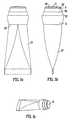
- an applicator 1 for use with a pack according to the invention is provided with a cap 2.
- the applicator is of moulded plastics material compatible with CA adhesives, and comprises a generally cylindrical hollow body 3, a generally cylindrical neck portion 4 which extends upwardly from the body, and a head 5 which closes the top of the applicator.
- the head is slightly domed with a dome radius of about 85 mm and the comer at the transition between the neck and the head is rounded with a comer radius of about 1 - 2 mm.
- the head of the applicator is integral with the body of the applicator as shown in the Figures.
- a cylindrical hollow receiver 6 Projecting downwardly from the head and spaced radially inwardly of the body there is a cylindrical hollow receiver 6, the lower part of which is internally screw-threaded. Spaced radially inwardly of the receiver 6, and also projecting downwardly from the head 5 there is a cylindrical hollow passage member 7 which at its open lower end thins down to form a cutting ring 8.
- the centre of the head 5 is penetrated by a (valveless) dispensing aperture 9 which provides an outlet from the interior of the passage member 7.
- the passage member 7 defines the conduit for supplying adhesive composition to the dispensing aperture.
- the upper portion of the neck 4, adjacent to the rounded comer, is cylindrical.
- the lower portion of the neck 4 is also cylindrical and is connected to the upper portion by a convex flared portion.
- annular step 9a at the transition between the neck 4 and body 3. This inhibits flow of adhesive composition downwardly providing flow inhibition means on the exterior of the applicator.
- annular step 10 a part of the way down the body 3. If desired, a lip (not shown) may be provided at the outer edge of the step 9a.
- the body has an outer surface which curves radially inwardly. The upper part of this curved surface carries a series of nibs 11 which facilitate manual gripping.
- the cap 2 comprises a skirt 12 and a top portion 13.
- the skirt 12 fits on the upper part of the body of the applicator, with its edge resting on the step 10.
- the cap engages on the applicator by screw thread engagement between respective rib formations 15 and 16, allowing a one-quarter turn release. The engagement is effective to seal the cap and applicator together.
- the cap 2 closes over the applicator 1 but leaves a gap between the two components to minimise the risk of bonding between them.
- the external surface of the top portion 13 is flat. At the centre of the top portion 13 of the cap there is a downwardly projecting pin 14 which fits into the dispensing aperture 9 and seals it. The pin does not extend fully through the aperture to reduce the likelihood of bonding.
- the pin may be integrally moulded in the cap or it may be a metal insert secured in the cap.
- the exterior of the cap 2 carries a series of ribs 11a which in the engaged position of the cap 2 are aligned with the ribs 11 on the applicator 1, again for the purpose of facilitating manual gripping.
- the cap 2 may conveniently be made of transparent, translucent or opaque plastics material, particularly a CA-compatible material.
- Figures 1(f) and 1(g) show the applicator mounted on a conventional flexible aluminium or plastics tube 17 suitable for holding an adhesive composition (e.g. in an amount of 5-20g).
- the tube 17 has an externally screw-threaded outlet 70 which is engageable in the internally screw-threaded portion of the receiver 6 of the applicator.
- the shoulder portion 18 of the tube 17 abuts against the body of the applicator.
- the outlet 70 of the tube before use is sealed by a metal membrane 71, which is pierced by the cutting ring 8 on the passage member 7 as the applicator is screwed down onto the tube.
- the interior of the tube is then placed in communication with the interior of the passage member 7 so that the adhesive composition can be urged towards the dispensing aperture 9 by squeezing the walls of the tube.
- the adhesive emerges onto the domed surface 19 of the applicator. It can then be spread across a substrate in a band which can be as wide as the diameter of the head 5 of the applicator. Because of the domed shape of the surface 19 the area of contact between the applicator and the substrate is minimised, thus reducing the risk of sticking when the adhesive cures instantly or very rapidly, and reducing the area of frictional contact.
- Adhesive which may unintentionally pass around the comer 20 is held by the step 9a so that it does not reach the upper part 21 of the body, where the cap will fit after use of the applicator. Thus the risk of the cap becoming adhered to the applicator is minimised. If necessary, the applicator can be wiped after use, for example by means of a paper tissue.
- Figures 1(f) and 1(g) are shown with the dispensing unit in inverted position compared to Figures 1(a) and 1(b). Because of the flat surface of the top portion 13 of the cap, the unit can conveniently be left standing in this position, with the result that the adhesive composition 72 remains in the region of the outlet 70 and passage member 7 and is immediately available to be dispensed on the next occasion when the unit is used.
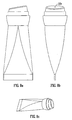
- Figure 2 shows the applicator with the cap removed albeit in this case an applicator adapted for mounting on a different size of tube.
- Figures 2(a) to 2(c) correspond to the views of Figures 1(a) to 1(c).
- Figures 2(d) shows a perspective view of the applicator while Figure 2(e) shows a sectional view of the cap alone.
- Figure 3 shows an applicator similar to that of Figure 1 with a dome radius of about 68 mm.
- the applicator is mounted on a tube 17 suitable for holding an adhesive composition (e.g. in an amount of 5-20g).
- Figures 4 and 5 show similar features to Figure 3 but with smaller tubes e.g. for 5-10g adhesive in Figure 4 and 2-5g adhesive in Figure 5.
- the dome radius is about 20 - 30 mm.
- Figure 6 shows an alternative embodiment having a tear band 21 attached to the lower edge of the body 3 of the applicator.
- the tear band 21 has an internal diameter smaller than the tube 17 at its shoulder 18, and a height sufficiently large so that the applicator cannot be screwed down onto the tube sufficiently for the cutting ring 8 to pierce the membrane of the tube outlet.
- the tear band 21 has a tab 22 by which it can be gripped and torn away from the applicator. Only when the tear band has been removed can the tube outlet be pierced to supply adhesive to the top surface.
- Figure 7 shows a further alternative embodiment in which the surface 19 of the top portion 5 is substantially plane but the comer 20 is rounded as in the previous embodiments.
- the plane surface permits satisfactory spreading of the adhesive onto a substrate.
- Figure 8 shows an embodiment similar to that of Figure 7 except that the top surface 19b of the applicator is not perpendicular to the axis of the applicator (and more importantly the axis of the tube which is the adhesive container) but is inclined thereto at an angle of about 5-20 degrees.
- This inclined surface facilitates the holding of the unit in a user's hand during the spreading of the adhesive in a band along a substrate.
- the surface 19b may be either plane or domed as in previous embodiments. Because of the inclined spreading surface, the uncapped unit cannot stand on the substrate, which reduces the risk of bonding between the applicator and the substrate.
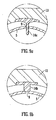
- Figure 9 comprises fragmentary enlarged sectional views of two alternative forms of pin 14, shown as metal inserts retained in the top portion 13 of the cap 2, although the pins could also be of plastics material and could be integrally moulded into the cap.
- the pin 14a is thin and elongated. In the sealed position (as shown) the pin 14a projects fully through the dispensing aperture. The use of this form of pin would assist in cleaning adhesive from the dispensing aperture.
- the applicator and applicator/cap assembly are shown as being attachable to a tube or other such separate container.
- the separate container is in all cases deformable, allowing for manual expression of the (viscous) contents of the container through the applicator.
- the applicator could be integrally formed with a container such as described below. However it is desirable that the applicator is attachable to an existing container and particularly by screw-thread engagement.
- the pin 14b is short and broad. It does not travel through the aperture 9, but enters it partially.
- the pin 14b has a domed end which seals against a seat surrounding the aperture 9.
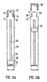
- Figure 10 shows two views of an alternative embodiment of the invention in which the applicator is integrated into the container.
- the container 50 is a rigid cylindrical shell which is closed at the top by an applicator portion 51 having a domed head 52 similar to the applicator of the previous embodiments.
- a cap 57 fits over the applicator and is screw-engageable therewith. There is a pin 58 on the cap which seals the aperture 9.
- a step 70 provides an anti-foul or adhesive retention means utilising the movement of adhesive onto the step 71 against which the cap 57 abuts in the closed configuration.
- Figure 11 shows 3 views of a further embodiment which is similar to that of Figure 10 except that the rotating spindle delivery mechanism is replaced by a squeezing mechanism. Similar to the earlier Figures an adhesive retention rim or step 73 is provided so as to prevent adhesive fouling the step 74 against which a cap of the container abuts in a closed configuration.
- a glue-stick type of container can be modified to receive a screw-engageable applicator of the kind shown in Figures 1-8.
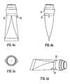
- Figures 12 to 14 show further embodiments of the applicator of the pack of the invention.
- the applicator is shown by itself for the purposes of illustration but it will be appreciated that the applicator could additionally have one or more of the features described above, for example it could be fitted with a cap as described above, with ribs which assist manual gripping, with a tear-away strip etc.
- the spreading surface is inclined and is domed (as shown in Figures 12-14 but which is most evident from Figure 12(a)).
- the head/spreading surface may be flat (a dome of infinite radius) and straight (non-inclined).
- the applicators shown are for dispensing viscous adhesive composition such as those described herein.
- the applicator 1 comprises a hollow body 3, a neck portion 4 which extends upwardly from the hollow body and a head 5 which closes the top of the applicator.
- the head 5 is slightly domed in each of Figures 12 to 14 but the domed shape is most evident from the view of Figure 12(a).
- the head has a dome radius of about 85 mm and the comer 20 at the transition between the neck and the head is rounded with a comer radius of about 1- 2 mm.
- the applicator may have a hollow receiver which would be very similar in configuration to the receiver 6 shown in earlier Figures (see for example Figure 1(b)).
- the center of the head of the applicator is penetrated by a dispensing aperture 9 which provides an outlet for the adhesive composition and functions as described above.
- a cap such as is shown in Figure 2(e) may be fitted to the applicators.
- the applicators are adapted for fitting to a conventional deformable adhesive tube.
- Each applicator 1 is provided with means for inhibiting flow of adhesive composition along the exterior of the applicator.
- this takes the form of a step or rim 80.
- Figures 12 to 14 The main purpose of providing Figures 12 to 14 is to illustrate the various types of non-porous spreading surface that can be provided and in particular the various shapes of applicator that may prove useful in practice for example for application of narrow bands of material e.g. for application of adhesive to substrates with relatively narrow areas for example comers etc.
- Figures 12(a) to 12(d) show a first type of applicator head.
- the head 5 of the applicator and indeed the neck portion 4 are irregularly shaped.
- the applicator head 5 and the neck portion 4 have a protruding portion 81 forming an extremity or comer.
- the presence of the protruding portion is to contrast with a general round (e.g. circular or elliptical shape cross-sectional shape such as the generally cylindrical shape shown in the earlier figures) which is not provided with a protruding portion.
- the protruding portion may be formed as part of the head 5 and not part of the (neck portion 4) of the applicator 1.
- neck portion 4 and the head 5 are similarly shaped and thus it is desirable that as shown that the protruding portion is not only arranged to form part of the spreading surface of the head 5 but also to form part of a neck portion 4 of the applicator 1.
- the aperture 9 is generally centrally located on the head 5 and that the alternative shape of the applicator provides at least one portion with a relatively large transverse dimension (for the application of a relatively wide band of adhesive) which in the embodiment shown is the transverse width of the head across the aperture.
- the applicator also has at least one portion (the protruding portion) of relatively narrow transverse width (taken in the same direction as, normally parallel to, the transverse width measurement of the portion of the applicator for applying the broad band of material) for applying a narrower band of material.
- the protruding portion or comer 81 can also be considered an integral wedge forming a wedge area on the head of the applicator.
- This wedge area formed by two edges (of the spreading surface) coinciding at a point (and converging toward that point) allows product to be applied in areas that are otherwise difficult to access.
- the unit can thus be used to apply adhesive on large surface areas and also smaller amounts/drops of adhesive on smaller more intricate zones.
- the protruding portion 81 can form the leading portion of the applicator when it is desired to apply adhesive in narrower bands or in hard to access areas.
- the portion 81 is formed by two convergent edges or sidewalls 82,83 on the applicator and in particular forming part of the neck portion 4 of the applicator.
- the sidewalls converge in a general v arrangement, meeting at a rounded apex 85.
- the remainder of the neck portion 4 forms a part-cylindrically shaped (in the embodiment semi-cylindrical) portion 84.
- FIG. 13 A further variation is shown in Figure 13. (For clarity all of the features of the applicator are not renumbered in Figures 13 and 14). As described above the configuration is similar in all material aspects except that the sidewalls 82,83 which converge to a rounded apex 81, each are curved inwardly toward the applicator, defining concave or recessed portions 86 which may further enhance the accessibility of the protruding portion 81 to confined or narrow areas.
- the broader surface area about the aperture toward the center of the applicator head 5 still allows for the application of broader bands of adhesive as desired and provides a broad receptive platform for receiving adhesive expressed through the aperture 9.
- FIG 14. A yet further embodiment is illustrated in Figure 14.
- the applicator has a generally square neck portion 4 and head 5.
- the head 5 is inclined. This allows for ease of manual application of adhesive as the applicator or a container to which it may be fitted may be held at an angle to the surface to which it is to be applied allowing for a more natural poise.
- the neck portion 4 has four walls 90 generally arranged in a rectangular configuration and meeting to form four rounded apices or comers 91.
- the packs in accordance with the invention are for use in dispensing high-viscosity adhesive compositions, more especially cyanoacrylate compositions, suitably in the form of a non-flowable gel.
- cyanoacrylate compositions which can be dispensed by the applicator.
- Examples 1-3 also describe compositions which can be solidified in a desired geometric form, for example in a cylindrical shape or "stick". They have rheological properties such that they can be expelled from a glue-stick type package but elastic properties such that they can be retracted easily and cleanly.
- Examples 4-8 below describe compositions which are particularly suitable for use with an applicator according to the invention having a closed head and a dispensing aperture penetrating the head.
- Bonding speed is defined as the minimum time required for a bonded assembly having a bond area of 322.6 mm 2 to support a weight of 3 kilos. Drying Time Formula 4 5 6 7 8 Drying Time (mins) 15 15 40 35 35 A standard commercial gel product took 8 minutes to dry in the same test.
Landscapes
- Engineering & Computer Science (AREA)
- Mechanical Engineering (AREA)
- Chemical & Material Sciences (AREA)
- Organic Chemistry (AREA)
- Adhesives Or Adhesive Processes (AREA)
- Closures For Containers (AREA)
- Coating Apparatus (AREA)
- Lubricants (AREA)
Claims (15)
- Verpackung, umfassend:(i) einen Behälter (17, 50), der eine viskose Klebstoffzusammensetzung (72) enthält;(ii) einen Applikator (1, 51) zur Abgabe einer viskosen Klebstoffzusammensetzung (72) aus dem Behälter (17, 50) auf ein Substrat, wobei der Applikator (1, 51) aufweist: einen Körper (3) mit einem verschlossenen Kopf (5, 52), eine abdichtbare ventillose Abgabeöffnung (9), die den Kopf durchdringt, Kanal- oder Abgabeeinrichtungen zur Zufuhr der Klebstoffzusammensetzung zur Abgabeöffnung (9), eine weite nichtporöse Auftragsoberfläche (19, 19B) auf dem Äußeren des Kopfs (5, 52) um die Abgabeöffnung (9) und Einrichtungen zum Hemmen eines Stroms von Klebstoffzusammensetzungen entlang dem Äußeren des Applikators, wobei die Einrichtungen zum Hemmen eines Stroms von Klebstoffzusammensetzungen eine ringförmige Stufe (9a, 73, 80) umfassen, die ein Stück des Wegs den Körper hinunter positioniert ist, an welchem Körper eine Kappe (2, 57) anbringbar ist.
- Verpackung nach Anspruch 1, bei der die Auftragsoberfläche (19, 19B) des Applikators (1, 51) kuppelförmig ist.
- Verpackung nach Anspruch 1 oder Anspruch 2, bei der der Kopf (5, 52) des Applikators (1, 51) eine Kante (20) am Perimeter der Auftragsoberfläche (19, 19B) aufweist.
- Verpackung nach Anspruch 3, bei der die Applikatorkante (20) gekrümmt ist.
- Verpackung nach Anspruch 3 oder Anspruch 4, bei der die Applikatorkante (20) vom Kopf (5, 52) in Richtung auf den Körper (3) verläuft.
- Verpackung nach einem der Ansprüche 3 bis 5, bei der die Applikatorkante (20) um den ganzen Perimeter der Auftragsoberfläche (19, 19B) verläuft.
- Verpackung nach einem der Ansprüche 3 bis 5, bei der die Applikatorkante (20) durch das Zusammenlaufen von zwei Rändern der Auftragsoberfläche (19, 19B) gebildet ist.
- Verpackung nach einem der Ansprüche 3 bis 7, bei der die Applikatorkante (20) auch im Körper (3) des Applikators (1, 51) gebildet ist.
- Verpackung nach einem der vorangehenden Ansprüche, bei der die Auftragsoberfläche (19, 19B) oder Applikator (1, 51) von einer im Allgemeinen rechteckigen Form ist oder im Allgemeinen keilförmig ist.
- Verpackung nach einem der vorangehenden Ansprüche in Kombination mit einer Kappe (2, 57), die über den Kopf (5, 52) passt und die eine Struktur (14, 14A, 14B, 48) im Innern der Kappe (2, 57) zum Eingriff mit der Abgabeöffnung (9) aufweist, um die Öffnung (9) zu verschließen.
- Verpackung nach einem der vorangehenden Ansprüche, die komplementäre Eingriffseinrichtungen auf dem Applikator (1, 51) bzw. dem Behälter (17, 50) aufweist.
- Verpackung nach einem der vorangehenden Ansprüche, bei der der Applikator (1, 51) eine Schneideinrichtung (8) zum Durchbohren eines Verschlusses (71) auf dem Behälter (17, 50) während des Verlaufs eines Ineinandergreifens der Eingriffseinrichtungen (6, 70) aufweist.
- Verpackung nach einem der vorangehenden Ansprüche, bei der der Behälter (17, 50) eine Alpha-Cyanoacrylatklebstoffzusammensetzung mit einer Casson-Unendlichscherviskosität im Bereich von 300-50000 mPa.s und einer Fließgrenze im Bereich 1-20 Pa enthält.
- Verpackung nach Anspruch 13, bei der die Klebstoffzusammensetzung ein Gel ist.
- Verpackung nach einem der Ansprüche 13 oder Anspruch 14, bei der die Klebstoffzusammensetzung einen Geruchsmaskierungszusatzstoff enthält, der mit der Zusammensetzung verträglich ist.
Applications Claiming Priority (3)
| Application Number | Priority Date | Filing Date | Title |
|---|---|---|---|
| IE20000445A IE20000445A1 (en) | 2000-06-01 | 2000-06-01 | Spreadable adhesive compositions and applicators for use therewith |
| IE000445 | 2000-06-01 | ||
| PCT/IE2001/000073 WO2001091915A2 (en) | 2000-06-01 | 2001-05-31 | Spreadable adhesive compositions and applicators for use therewith |
Publications (2)
| Publication Number | Publication Date |
|---|---|
| EP1286786A2 EP1286786A2 (de) | 2003-03-05 |
| EP1286786B1 true EP1286786B1 (de) | 2005-01-12 |
Family
ID=11042622
Family Applications (1)
| Application Number | Title | Priority Date | Filing Date |
|---|---|---|---|
| EP01936750A Expired - Lifetime EP1286786B1 (de) | 2000-06-01 | 2001-05-31 | Auftragsvorrichtung zur verwendung mit schmierbarer kunststoffzusammensetzung |
Country Status (10)
| Country | Link |
|---|---|
| US (1) | US20030172987A1 (de) |
| EP (1) | EP1286786B1 (de) |
| AT (1) | ATE286786T1 (de) |
| AU (1) | AU2001262609A1 (de) |
| BR (1) | BR0111305A (de) |
| CA (1) | CA2410645A1 (de) |
| DE (1) | DE60108378D1 (de) |
| HU (1) | HUP0302289A3 (de) |
| IE (1) | IE20000445A1 (de) |
| WO (1) | WO2001091915A2 (de) |
Families Citing this family (5)
| Publication number | Priority date | Publication date | Assignee | Title |
|---|---|---|---|---|
| CN1311061C (zh) | 2001-10-29 | 2007-04-18 | 亨凯尔公司 | 固体形式的抗卡组合物 |
| CA2573924A1 (en) * | 2004-07-14 | 2006-01-19 | Acrux Dds Pty Ltd | Cap with seal moved by rotatable collar and receptacle with spreading surface |
| US8192731B2 (en) * | 2005-10-25 | 2012-06-05 | Loctite (R&D) Limited | Thickened cyanoacrylate compositions |
| US9457613B2 (en) | 2008-09-26 | 2016-10-04 | Henkel IP & Holding GmbH | Cyanoacrylate compositions in non-flowable forms |
| US20130288951A1 (en) * | 2012-04-27 | 2013-10-31 | Biomet Manufacturing Corp. | Compositions and methods for coating implant surfaces to inhibit surgical infections |
Family Cites Families (37)
| Publication number | Priority date | Publication date | Assignee | Title |
|---|---|---|---|---|
| US1323869A (en) * | 1919-12-02 | Jajtsfi l kra | ||
| US1374236A (en) * | 1920-03-22 | 1921-04-12 | Robert R Ritz | Combined container and liquid-spreader |
| GB733653A (en) * | 1952-11-19 | 1955-07-13 | Jones & Co Ltd Samuel | Dispensers for gum |
| DE1928880A1 (de) * | 1969-06-06 | 1970-12-17 | Otto Gassenmaier | Auftragsvorrichtung fuer fluessige und cremeartige Mittel |
| DE2054667A1 (de) * | 1970-11-06 | 1972-05-10 | Henkel & Cie. GmbH, 4000 Düsseldorf | Verschluß für Klebstoffbehälter |
| FR2214247A5 (de) * | 1973-01-15 | 1974-08-09 | Eparco Sa | |
| US4309334A (en) * | 1975-10-08 | 1982-01-05 | Loctite Corporation | Thermally-resistant glass-filled adhesive/sealant compositions |
| JPS6037836B2 (ja) * | 1977-08-05 | 1985-08-28 | 東亞合成株式会社 | 接着剤組成物 |
| US4111890A (en) * | 1977-12-19 | 1978-09-05 | Sws Silicones Corporation | Curable organopolysiloxane compositions containing titanium esters |
| US4201808A (en) * | 1978-06-12 | 1980-05-06 | Union Carbide Corporation | Radiation curable silicone release compositions |
| US4252526A (en) * | 1979-05-24 | 1981-02-24 | Sybron Corporation | Barium aluminum silicate filler for U.V. curable composites |
| US4271982A (en) * | 1979-09-14 | 1981-06-09 | Dynatron/Bondo Corporation | Glue dispenser |
| IE51863B1 (en) * | 1980-08-28 | 1987-04-15 | Loctite Corp | Additive for cyanoacrylate adhesives |
| US4348454A (en) * | 1981-03-02 | 1982-09-07 | General Electric Company | Ultraviolet light curable acrylic functional silicone compositions |
| US4548524A (en) * | 1982-07-22 | 1985-10-22 | Calumet Manufacturing Co. | Dispensing package with applicator surface |
| US4528081A (en) * | 1983-10-03 | 1985-07-09 | Loctite Corporation | Dual curing silicone, method of preparing same and dielectric soft-gel compositions thereof |
| US4675346A (en) * | 1983-06-20 | 1987-06-23 | Loctite Corporation | UV curable silicone rubber compositions |
| US4533422A (en) * | 1983-08-31 | 1985-08-06 | Loctite Corporation | Thixotropic cyanoacrylate compositions |
| US4699802A (en) * | 1983-10-03 | 1987-10-13 | Loctite Corporation | Dual curing coating method for substrates with shadow areas |
| JPH0694548B2 (ja) | 1985-07-19 | 1994-11-24 | 高圧ガス工業株式会社 | α―シアノアクリレート接着剤組成物 |
| US4837260A (en) * | 1986-05-23 | 1989-06-06 | Toagosei Chemical Industry Co., Ltd. | Cyanoacrylate compositions |
| US4753704A (en) * | 1986-06-30 | 1988-06-28 | Loctite Corporation | Process using light and light activated adhesive compositions to secure light opaque end caps to fluorescent tubes |
| JPH0742444B2 (ja) | 1986-11-29 | 1995-05-10 | 株式会社スリ−ボンド | α−シアノアクリレ−ト系組成物 |
| GB2204872B (en) | 1987-04-07 | 1991-02-20 | Chemence Ltd | A psuedoplastic cyanoacrylate composition |
| JPH0747714B2 (ja) | 1987-10-15 | 1995-05-24 | 積水アイコー株式会社 | シアノ系接着剤組成物 |
| JPH0228275A (ja) | 1988-07-15 | 1990-01-30 | Kansai Polymer Kenkyusho:Kk | 接着剤組成物 |
| FR2635086B1 (fr) * | 1988-08-03 | 1991-01-25 | Emballages Conseils Etudes | Embout applicateur pour tubes a bague a vis et autres recipients |
| JPH02142875A (ja) | 1988-11-22 | 1990-05-31 | Sekisui Aikoo Kk | α−シアノアクリレート系接着剤組成物 |
| JPH0757859B2 (ja) | 1990-11-05 | 1995-06-21 | 積水アイコー株式会社 | α―シアノアクリレート系接着剤組成物 |
| US5362769A (en) * | 1992-05-07 | 1994-11-08 | Ormco Corporation | Orthodontic adhesives |
| JP3341168B2 (ja) | 1992-10-09 | 2002-11-05 | 大原パラヂウム化学株式会社 | 接着剤組成物 |
| DE69503844T2 (de) | 1994-06-08 | 1999-04-22 | Taoka Chemical Co., Ltd., Osaka | Klebemittelzusammensetzung auf Alphacyanoacrylat Basis |
| US5567266A (en) * | 1994-10-13 | 1996-10-22 | Loctite Corporation | Non-environmentally hazardous, non-volatile adhesive promoter composition for curing adhesives |
| JPH10337523A (ja) * | 1997-06-06 | 1998-12-22 | Toagosei Co Ltd | ペンタイプの瞬間接着剤容器 |
| EP0922645A1 (de) * | 1997-12-11 | 1999-06-16 | Gurit-Essex AG | Applikator für dünnflussige Medien |
| WO1999062960A1 (en) * | 1998-06-01 | 1999-12-09 | Loctite Corporation | Flame-retardant uv curable silicone compositions |
| US6323253B1 (en) * | 1998-06-01 | 2001-11-27 | Loctite Corporation | Flame-retardant UV and UV/moisture curable silicone compositions |
-
2000
- 2000-06-01 IE IE20000445A patent/IE20000445A1/en not_active IP Right Cessation
-
2001
- 2001-05-31 CA CA002410645A patent/CA2410645A1/en not_active Abandoned
- 2001-05-31 US US10/296,545 patent/US20030172987A1/en not_active Abandoned
- 2001-05-31 EP EP01936750A patent/EP1286786B1/de not_active Expired - Lifetime
- 2001-05-31 HU HU0302289A patent/HUP0302289A3/hu unknown
- 2001-05-31 BR BR0111305-4A patent/BR0111305A/pt not_active Application Discontinuation
- 2001-05-31 DE DE60108378T patent/DE60108378D1/de not_active Expired - Lifetime
- 2001-05-31 WO PCT/IE2001/000073 patent/WO2001091915A2/en not_active Ceased
- 2001-05-31 AT AT01936750T patent/ATE286786T1/de not_active IP Right Cessation
- 2001-05-31 AU AU2001262609A patent/AU2001262609A1/en not_active Abandoned
Also Published As
| Publication number | Publication date |
|---|---|
| HUP0302289A3 (en) | 2004-12-28 |
| DE60108378D1 (de) | 2005-02-17 |
| WO2001091915A3 (en) | 2002-03-21 |
| BR0111305A (pt) | 2004-04-20 |
| EP1286786A2 (de) | 2003-03-05 |
| HUP0302289A2 (hu) | 2003-10-28 |
| AU2001262609A1 (en) | 2001-12-11 |
| CA2410645A1 (en) | 2001-12-06 |
| IE20000445A1 (en) | 2003-04-02 |
| WO2001091915A2 (en) | 2001-12-06 |
| US20030172987A1 (en) | 2003-09-18 |
| ATE286786T1 (de) | 2005-01-15 |
Similar Documents
| Publication | Publication Date | Title |
|---|---|---|
| ES2541529T3 (es) | Adhesivos activables por fluido y fluidos para activar los mismos para el uso con etiquetas libres de revestimiento | |
| US8192731B2 (en) | Thickened cyanoacrylate compositions | |
| US10626310B2 (en) | Fast light curing cyanoacrylate compositions | |
| US6435873B1 (en) | Medication delivery devices | |
| US4946081A (en) | Applicator nozzle for sealant cartridges and the like | |
| CN1080750C (zh) | 圆珠笔用油墨随动液组合物及使用这种随动液的圆珠笔 | |
| DE60215243D1 (de) | Mascara enthaltend einen Acrylatpolymer | |
| WO2000010477A3 (en) | Unit dose liquid dispensing and packaging for dental application | |
| US5409977A (en) | Repositional glue stick | |
| US20030172987A1 (en) | Spreadable adhesive compositions and applicators for use therewith | |
| US20030031499A1 (en) | Quenched foam applicators for polymerizable adhesives, and methods of making and using the same | |
| KR20010107993A (ko) | 시아노아크릴레이트 및 알데히드 또는 케톤 축합 생성물로구성된, 결합, 코팅 및 밀봉용 물질 | |
| US6450717B1 (en) | Applicator and method of applying | |
| FI93552C (fi) | Liimapuikko | |
| ECSP941093A (es) | Gel tixotropico para pegar madera | |
| KR20040030482A (ko) | 알파-시아노아크릴레이트 접착제 시스템 | |
| IE20000439A1 (en) | Semi-Solid Primer Compositions | |
| US20050047845A1 (en) | Self-contained system and method for substance application | |
| EP1957206B1 (de) | Applikator für tubenspender für klebstoffkomponenten niedriger und hoher viskosität | |
| US20030130150A1 (en) | Semi- solid compositions for removing cured product | |
| JPH0995650A (ja) | 再剥離性粘着シート | |
| WO1994011207A1 (en) | Block of paint and its use | |
| JP4435292B2 (ja) | ボールペン型接着具用水性接着組成物及びそれを内蔵したボールペン型接着具 | |
| CN208279545U (zh) | 一种粘性极强的草坪胶带 | |
| JP2007084507A (ja) | 皮膚接着組成物 |
Legal Events
| Date | Code | Title | Description |
|---|---|---|---|
| PUAI | Public reference made under article 153(3) epc to a published international application that has entered the european phase |
Free format text: ORIGINAL CODE: 0009012 |
|
| 17P | Request for examination filed |
Effective date: 20021213 |
|
| AK | Designated contracting states |
Kind code of ref document: A2 Designated state(s): AT BE CH CY DE DK ES FI FR GB GR IE IT LI LU MC NL PT SE TR |
|
| AX | Request for extension of the european patent |
Extension state: AL LT LV MK RO SI |
|
| 17Q | First examination report despatched |
Effective date: 20030814 |
|
| GRAP | Despatch of communication of intention to grant a patent |
Free format text: ORIGINAL CODE: EPIDOSNIGR1 |
|
| RTI1 | Title (correction) |
Free format text: APPLICATOR PACKS FOR USE WITH SPREADABLE ADHESIVE COMPOSITIONS |
|
| GRAA | (expected) grant |
Free format text: ORIGINAL CODE: 0009210 |
|
| GRAS | Grant fee paid |
Free format text: ORIGINAL CODE: EPIDOSNIGR3 |
|
| PGFP | Annual fee paid to national office [announced via postgrant information from national office to epo] |
Ref country code: SE Payment date: 20050101 Year of fee payment: 5 |
|
| AK | Designated contracting states |
Kind code of ref document: B1 Designated state(s): AT BE CH CY DE DK ES FI FR GB GR IE IT LI LU MC NL PT SE TR |
|
| PG25 | Lapsed in a contracting state [announced via postgrant information from national office to epo] |
Ref country code: IT Free format text: LAPSE BECAUSE OF FAILURE TO SUBMIT A TRANSLATION OF THE DESCRIPTION OR TO PAY THE FEE WITHIN THE PRESCRIBED TIME-LIMIT;WARNING: LAPSES OF ITALIAN PATENTS WITH EFFECTIVE DATE BEFORE 2007 MAY HAVE OCCURRED AT ANY TIME BEFORE 2007. THE CORRECT EFFECTIVE DATE MAY BE DIFFERENT FROM THE ONE RECORDED. Effective date: 20050112 Ref country code: BE Free format text: LAPSE BECAUSE OF FAILURE TO SUBMIT A TRANSLATION OF THE DESCRIPTION OR TO PAY THE FEE WITHIN THE PRESCRIBED TIME-LIMIT Effective date: 20050112 Ref country code: AT Free format text: LAPSE BECAUSE OF FAILURE TO SUBMIT A TRANSLATION OF THE DESCRIPTION OR TO PAY THE FEE WITHIN THE PRESCRIBED TIME-LIMIT Effective date: 20050112 Ref country code: TR Free format text: LAPSE BECAUSE OF FAILURE TO SUBMIT A TRANSLATION OF THE DESCRIPTION OR TO PAY THE FEE WITHIN THE PRESCRIBED TIME-LIMIT Effective date: 20050112 Ref country code: FR Free format text: LAPSE BECAUSE OF NON-PAYMENT OF DUE FEES Effective date: 20050112 Ref country code: LI Free format text: LAPSE BECAUSE OF FAILURE TO SUBMIT A TRANSLATION OF THE DESCRIPTION OR TO PAY THE FEE WITHIN THE PRESCRIBED TIME-LIMIT Effective date: 20050112 Ref country code: FI Free format text: LAPSE BECAUSE OF FAILURE TO SUBMIT A TRANSLATION OF THE DESCRIPTION OR TO PAY THE FEE WITHIN THE PRESCRIBED TIME-LIMIT Effective date: 20050112 Ref country code: CH Free format text: LAPSE BECAUSE OF FAILURE TO SUBMIT A TRANSLATION OF THE DESCRIPTION OR TO PAY THE FEE WITHIN THE PRESCRIBED TIME-LIMIT Effective date: 20050112 Ref country code: NL Free format text: LAPSE BECAUSE OF FAILURE TO SUBMIT A TRANSLATION OF THE DESCRIPTION OR TO PAY THE FEE WITHIN THE PRESCRIBED TIME-LIMIT Effective date: 20050112 |
|
| REG | Reference to a national code |
Ref country code: GB Ref legal event code: FG4D |
|
| REG | Reference to a national code |
Ref country code: CH Ref legal event code: EP |
|
| REF | Corresponds to: |
Ref document number: 60108378 Country of ref document: DE Date of ref document: 20050217 Kind code of ref document: P |
|
| REG | Reference to a national code |
Ref country code: IE Ref legal event code: FG4D |
|
| PG25 | Lapsed in a contracting state [announced via postgrant information from national office to epo] |
Ref country code: DK Free format text: LAPSE BECAUSE OF FAILURE TO SUBMIT A TRANSLATION OF THE DESCRIPTION OR TO PAY THE FEE WITHIN THE PRESCRIBED TIME-LIMIT Effective date: 20050412 Ref country code: SE Free format text: LAPSE BECAUSE OF FAILURE TO SUBMIT A TRANSLATION OF THE DESCRIPTION OR TO PAY THE FEE WITHIN THE PRESCRIBED TIME-LIMIT Effective date: 20050412 |
|
| PG25 | Lapsed in a contracting state [announced via postgrant information from national office to epo] |
Ref country code: DE Free format text: LAPSE BECAUSE OF FAILURE TO SUBMIT A TRANSLATION OF THE DESCRIPTION OR TO PAY THE FEE WITHIN THE PRESCRIBED TIME-LIMIT Effective date: 20050413 |
|
| PG25 | Lapsed in a contracting state [announced via postgrant information from national office to epo] |
Ref country code: ES Free format text: LAPSE BECAUSE OF FAILURE TO SUBMIT A TRANSLATION OF THE DESCRIPTION OR TO PAY THE FEE WITHIN THE PRESCRIBED TIME-LIMIT Effective date: 20050423 |
|
| PGFP | Annual fee paid to national office [announced via postgrant information from national office to epo] |
Ref country code: MC Payment date: 20050504 Year of fee payment: 5 |
|
| PGFP | Annual fee paid to national office [announced via postgrant information from national office to epo] |
Ref country code: FR Payment date: 20050517 Year of fee payment: 5 |
|
| PGFP | Annual fee paid to national office [announced via postgrant information from national office to epo] |
Ref country code: IE Payment date: 20050518 Year of fee payment: 5 |
|
| PGFP | Annual fee paid to national office [announced via postgrant information from national office to epo] |
Ref country code: LU Payment date: 20050525 Year of fee payment: 5 |
|
| PG25 | Lapsed in a contracting state [announced via postgrant information from national office to epo] |
Ref country code: GB Free format text: LAPSE BECAUSE OF NON-PAYMENT OF DUE FEES Effective date: 20050531 Ref country code: CY Free format text: LAPSE BECAUSE OF FAILURE TO SUBMIT A TRANSLATION OF THE DESCRIPTION OR TO PAY THE FEE WITHIN THE PRESCRIBED TIME-LIMIT Effective date: 20050531 |
|
| PGFP | Annual fee paid to national office [announced via postgrant information from national office to epo] |
Ref country code: DE Payment date: 20050630 Year of fee payment: 5 |
|
| NLV1 | Nl: lapsed or annulled due to failure to fulfill the requirements of art. 29p and 29m of the patents act | ||
| REG | Reference to a national code |
Ref country code: CH Ref legal event code: PL |
|
| PLBE | No opposition filed within time limit |
Free format text: ORIGINAL CODE: 0009261 |
|
| STAA | Information on the status of an ep patent application or granted ep patent |
Free format text: STATUS: NO OPPOSITION FILED WITHIN TIME LIMIT |
|
| 26N | No opposition filed |
Effective date: 20051013 |
|
| GBPC | Gb: european patent ceased through non-payment of renewal fee |
Effective date: 20050531 |
|
| EN | Fr: translation not filed | ||
| PG25 | Lapsed in a contracting state [announced via postgrant information from national office to epo] |
Ref country code: IE Free format text: LAPSE BECAUSE OF NON-PAYMENT OF DUE FEES Effective date: 20060531 Ref country code: MC Free format text: LAPSE BECAUSE OF NON-PAYMENT OF DUE FEES Effective date: 20060531 |
|
| REG | Reference to a national code |
Ref country code: IE Ref legal event code: MM4A |
|
| PG25 | Lapsed in a contracting state [announced via postgrant information from national office to epo] |
Ref country code: PT Free format text: LAPSE BECAUSE OF NON-PAYMENT OF DUE FEES Effective date: 20050612 |
|
| PG25 | Lapsed in a contracting state [announced via postgrant information from national office to epo] |
Ref country code: GR Free format text: LAPSE BECAUSE OF NON-PAYMENT OF DUE FEES Effective date: 20050112 |
|
| PG25 | Lapsed in a contracting state [announced via postgrant information from national office to epo] |
Ref country code: LU Free format text: LAPSE BECAUSE OF NON-PAYMENT OF DUE FEES Effective date: 20060531 |