EP1281880A2 - Kugelumlaufspindel - Google Patents
Kugelumlaufspindel Download PDFInfo
- Publication number
- EP1281880A2 EP1281880A2 EP02017415A EP02017415A EP1281880A2 EP 1281880 A2 EP1281880 A2 EP 1281880A2 EP 02017415 A EP02017415 A EP 02017415A EP 02017415 A EP02017415 A EP 02017415A EP 1281880 A2 EP1281880 A2 EP 1281880A2
- Authority
- EP
- European Patent Office
- Prior art keywords
- nut
- ball
- balls
- groove
- shaft
- Prior art date
- Legal status (The legal status is an assumption and is not a legal conclusion. Google has not performed a legal analysis and makes no representation as to the accuracy of the status listed.)
- Granted
Links
Images


Classifications
-
- F—MECHANICAL ENGINEERING; LIGHTING; HEATING; WEAPONS; BLASTING
- F16—ENGINEERING ELEMENTS AND UNITS; GENERAL MEASURES FOR PRODUCING AND MAINTAINING EFFECTIVE FUNCTIONING OF MACHINES OR INSTALLATIONS; THERMAL INSULATION IN GENERAL
- F16H—GEARING
- F16H25/00—Gearings comprising primarily only cams, cam-followers and screw-and-nut mechanisms
- F16H25/18—Gearings comprising primarily only cams, cam-followers and screw-and-nut mechanisms for conveying or interconverting oscillating or reciprocating motions
- F16H25/20—Screw mechanisms
- F16H25/22—Screw mechanisms with balls, rollers, or similar members between the co-operating parts; Elements essential to the use of such members
- F16H25/2204—Screw mechanisms with balls, rollers, or similar members between the co-operating parts; Elements essential to the use of such members with balls
- F16H25/2214—Screw mechanisms with balls, rollers, or similar members between the co-operating parts; Elements essential to the use of such members with balls with elements for guiding the circulating balls
-
- F—MECHANICAL ENGINEERING; LIGHTING; HEATING; WEAPONS; BLASTING
- F16—ENGINEERING ELEMENTS AND UNITS; GENERAL MEASURES FOR PRODUCING AND MAINTAINING EFFECTIVE FUNCTIONING OF MACHINES OR INSTALLATIONS; THERMAL INSULATION IN GENERAL
- F16H—GEARING
- F16H25/00—Gearings comprising primarily only cams, cam-followers and screw-and-nut mechanisms
- F16H25/18—Gearings comprising primarily only cams, cam-followers and screw-and-nut mechanisms for conveying or interconverting oscillating or reciprocating motions
- F16H25/20—Screw mechanisms
- F16H25/22—Screw mechanisms with balls, rollers, or similar members between the co-operating parts; Elements essential to the use of such members
- F16H25/2204—Screw mechanisms with balls, rollers, or similar members between the co-operating parts; Elements essential to the use of such members with balls
- F16H2025/2242—Thread profile of the screw or nut showing a pointed "gothic" arch in cross-section
-
- Y—GENERAL TAGGING OF NEW TECHNOLOGICAL DEVELOPMENTS; GENERAL TAGGING OF CROSS-SECTIONAL TECHNOLOGIES SPANNING OVER SEVERAL SECTIONS OF THE IPC; TECHNICAL SUBJECTS COVERED BY FORMER USPC CROSS-REFERENCE ART COLLECTIONS [XRACs] AND DIGESTS
- Y10—TECHNICAL SUBJECTS COVERED BY FORMER USPC
- Y10T—TECHNICAL SUBJECTS COVERED BY FORMER US CLASSIFICATION
- Y10T74/00—Machine element or mechanism
- Y10T74/19—Gearing
- Y10T74/19642—Directly cooperating gears
- Y10T74/19698—Spiral
- Y10T74/19702—Screw and nut
- Y10T74/19721—Thread geometry
-
- Y—GENERAL TAGGING OF NEW TECHNOLOGICAL DEVELOPMENTS; GENERAL TAGGING OF CROSS-SECTIONAL TECHNOLOGIES SPANNING OVER SEVERAL SECTIONS OF THE IPC; TECHNICAL SUBJECTS COVERED BY FORMER USPC CROSS-REFERENCE ART COLLECTIONS [XRACs] AND DIGESTS
- Y10—TECHNICAL SUBJECTS COVERED BY FORMER USPC
- Y10T—TECHNICAL SUBJECTS COVERED BY FORMER US CLASSIFICATION
- Y10T74/00—Machine element or mechanism
- Y10T74/19—Gearing
- Y10T74/19642—Directly cooperating gears
- Y10T74/19698—Spiral
- Y10T74/19702—Screw and nut
- Y10T74/19744—Rolling element engaging thread
- Y10T74/19749—Recirculating rolling elements
Definitions
- the present invention relates to a ball screw used to threadedly engage a shaft and a nut with each other through a large number of balls and, in particular, to a ball screw which can cope with a large rating load and a reduction in noises.
- the ball screw is designed to increase number of balls receiving a load within a nut of the ball screw.
- the ball screw is designed such that the number of balls in a ball line defined by a single circulation member (a member which allows the balls to circulate endlessly therealong) is increased, the balls are easy to rub against each other in the area where the loads applied to the balls, which has an ill effect on the operation performance of the ball screw. It is also known that such mutual rubbing actions of the balls have an ill effect not only on the operation performance of the ball screw but also on the wear of the balls and ball grooves.
- a system in which the closed circuit of the ball line defined by the single circulation member is divided into a plurality of circuits, that is, as shown in Fig. 6, a plurality of ball 2 lines are respectively defined by a plurality of circulation members 6.
- reference character 1 designates a shaft, 2 a ball, and 3 a nut, respectively.
- the present invention aims at improving the drawbacks found in the above-mentioned conventional ball screws. Accordingly, it is an object of the present invention to provide a ball screw which is low in noise, is excellent in operation performance and load balance, is low in cost, and is simple in structure.
- a ball screw comprising: a shaft including a spiral-shaped shaft groove having a semicircular-shaped section; a nut including a spiral-shaped nut ball groove corresponding to the shaft groove and having a semicircular-shaped section; a large number of balls rotatably fitted between the nut ball groove and the shaft groove so as to be held by and between the two grooves; and, a circulation member defining a ball circulation passage for allowing the balls to circulate endlessly therealong, wherein a portion of the nut ball groove is formed larger in the effective diameter than the remaining portions of the nut.
- a ball screw comprising: a shaft including a spiral-shaped shaft groove having a semicircular-shaped section; a nut including a spiral-shaped nut ball groove corresponding to the shaft groove and having a semicircular-shaped section; a large number of balls rotatably fitted between the nut ball groove and the shaft groove so as to be held by and between the two grooves; and, a circulation member defining a ball circulation passage for allowing the balls to circulate endlessly therealong, wherein a width of a portion of the nut ball groove is formed larger than that of the remaining portions of the nut with the depth of the portion of the nut ball groove remaining.
- a ball screw as set forth in the first or second aspect of the present invention, wherein the portion of the nut ball groove formed larger than the remaining portions of the nut is disposed in a plurality of portions of the nut.
- a ball screw as set forth in the first or second aspect of the present invention, wherein when a number of a load area is set n, a number of the portion of the nut ball groove formed larger than the remaining portions of the nut is set n-1.
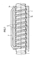
- Fig. 1 is a section view of a ball screw according to the present embodiment of the present invention
- Fig. 2 is an enlarged view of a portion enclosed by an oval (O) mark shown in Fig. 1 when the inner peripheral surface of a nut is viewed from the shaft side of the ball screw
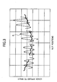
- Fig. 3 is a characteristic view of the relation between the ball loads and nut positions.
- a shaft 1 includes a shaft groove 1a which is formed in a spiral shape and has a semicircular-shaped (Gothic-arch-shaped) section, a large number of balls (steel balls) 2 are fitted into the shaft groove 1a, and a nut ball groove 3a, which is so formed in a nut 3 as to have a spiral shape and also has a semicircular-shaped (Gothic-arch-shaped) section, is threadedly engaged with the balls 2.
- the two end portions of the line of the balls 2 are respectively contacted with the two end portions of a ball circulation member (a return tube) 4, while the nut 3 includes a closed circuit which is composed of the single circulation member 4 and the line of the balls 2.
- the circulation member 4 is fixed to the nut 3. Due to the relative rotation between the shaft 1 and nut 3, the balls 2 are allowed to circulate in the closed circuit, whereby the shaft 1 and nut 3 are spirally rotated with respect to each other.
- a portion (in Fig. 1, a portion enclosed by an oval) of the nut ball groove 3a of the nut 3, as shown in Fig. 2 as well, is formed such that the ball center diameter of the semicircular shape of the section thereof (the dimension of the diameter of a circle drawn by each of the balls 2 interposed between the ball grooves 1a and 3a of the shaft 1 and nut 3, the effective diameter described in the above) is set slightly larger than that of the remaining portions thereof (for example, 10 ⁇ m), with the result that this portion provides a large-diameter portion 5 so formed as to have a width R2 slightly larger than the width R1 of the semicircular-shaped groove of the nut (R1 ⁇ R2).
- the degree of an increase in the width R2 of the large-diameter portion 5 over the width R1 should be set such that, even when an external load is applied to the nut 3, the balls 2 can be prevented from receiving the load; that is, the degree should be set not too large.
- the length of the large-diameter portion 5 along the spiral-shaped groove may range from a length equivalent to the lengths of two balls to a length corresponding to a half winding of the ball line along the spiral-shaped groove.
- the total number of balls 2 existing in the upper half section may be the number corresponding to 4.5 windings and, in the lower half section, the length of the large-diameter portion 5 may be the length equal to or more than the lengths of two balls 2. Therefore, there is eliminated the difference between the upper and lower half sections, which makes it possible to arrange the load balls 2 so as to balance well in the circumferential direction of the shaft 1. As a result of this, the loads to be applied to the respective balls 2 can be made to balance well.
- Fig. 3 shows the difference between the conventional ball screw in which, as shown in Fig. 6, the circulation members 6 are arranged on one side and the ball screw according to the present invention in which the load balls 2 are arranged in a good balance in the relation between the loads to be applied to the balls 2 and the positions of the nut 3 with respect to the shaft 1.
- a fine solid line A expresses the conventional ball screw in which the load balls 2 do not balance well
- a bold solid line B expresses the ball screw according to the present invention in which the load balls 2 balance well.
- the degree of variations in the ball loads with respect to the positions of the nut 3 shows the good or poor balance of the loads.
- B when compared with the conventional ball screw (A), not only the variations in the loads per lead but also the variations in the loads in the entire nut 3 are reduced greatly, which shows that the load balance is improved.
- the large-diameter portion 5 is not limited in number to one but it may be disposed in a plurality of portions; and, the number of large-diameter portions 5 may be decided according to the load balance and the number of balls 2.
- the position of the large-diameter portion 5 may be set in such a manner that the balls 2 receiving loads balance well. For example, in case where the load area is set for n portions, with the balance in the circumferential direction of the shaft 1 taken into account, the large-diameter portion 5 may be arranged in (n-1) portions.
- Fig. 4A shows an embodiment of the present invention having two large-diameter portions 5.
- the two large-diameter portions 5 enclosed by two ovals are disposed in an opposite side of the circulation member 4.
- Fig. 4B shows an embodiment of the present invention having two large-diameter portions 5.
- the two large-diameter portions 5 enclosed by two ovals are disposed in an opposite side of the circulation member 4 and separated from each other in the longitudinal and width direction of the nut 3.
- the line of the balls 2 is divided into three portions in a circumferential direction of the shaft 1.
- the total winding number of the balls 2 is divided not simply but so as to arrange no-loaded portions with the well balance in the circumferential direction of the shaft 1.
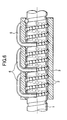
- Fig. 4C shows an embodiment of the present invention having three large-diameter portions 5 enclosed by three ovals.
- one of the three large-diameter portions 5 is disposed in an upper half section of the shaft 1, when the shaft 1 is viewed from the side surface side thereof.
- two of them are disposed in a lower half section and separated from each other in the axial direction of the shaft 1.
- the large-diameter portions 5 are divided so as to arrange load balance loaded on the balls 2 with the well balance.
- a method in which the effective diameter of the nut ball groove 3a is increased is not limitative but, for example, in another method in which only the width of the nut ball groove 3a is increased (the depth of the nut ball groove 3a remains unchanged), there can also be expected a similar effect.
- Fig.5A there is a construction forming a clearance gap between the ball 2 and the nut ball groove 3a due to increase the effective diameter thereof.
- the depth of the nut ball groove 3a is increased in the diameter direction of the nut without changing the shape thereof.
- Fig.5B there is a construction forming a clearance gap between the ball 2 and the nut ball groove 3a due to change the shape in the width direction thereof.
- the width of the nut ball groove 3a is increased so as to change the shape thereof.
- Fig.5C there is a construction forming a clearance gap between the ball 2 and the nut ball groove 3a due to change a lead of the nut ball groove 3a partially.
- the position of the nut ball groove 3a is changed in the longitudinal direction of the nut without changing the shape of the nut ball groove.
- a ball screw of a tube type By the way, in the present embodiment, description has been given of a ball screw of a tube type. However, this is not limitative but, for example, in a ball screw of other type using a different circulation member such as an end cap or a guide plate, there can also be expected a similar effect. Also, to prevent the balls from rubbing against one another, the circulationmember can alsobe used in combination with a retaining piece (a resin-made retainer) which is used while it is inserted between the balls.
- a retaining piece a resin-made retainer
- the nut ball groove of the nut is structured such that the effective diameter of a portion thereof is larger than that of the remaining portions thereof, even when the external load is applied to the ball screw, the loads to be applied to the balls can be reduced and the degree of balls rubbing against one another can be eased. This can reduce the wear of the balls due to the balls' mutual rubbing actions and can keep the operation performance of the ball screw at a good level.
- the number of ball circulation members can be reduced over the conventional ball screw, the amount of working on the nut side for installation of the ball circulation members can be reduced, which makes it possible to reduce the cost of the ball screw and noises.
- the load balls can be arranged so as to balance well in the circumferential direction of the shaft, the length of the nut can be used effectively as well as the effective life of the ball screw can be prolonged.
Landscapes
- Engineering & Computer Science (AREA)
- General Engineering & Computer Science (AREA)
- Mechanical Engineering (AREA)
- Transmission Devices (AREA)
Applications Claiming Priority (2)
| Application Number | Priority Date | Filing Date | Title |
|---|---|---|---|
| JP2001236569A JP4729821B2 (ja) | 2001-08-03 | 2001-08-03 | ボールねじ |
| JP2001236569 | 2001-08-03 |
Publications (3)
| Publication Number | Publication Date |
|---|---|
| EP1281880A2 true EP1281880A2 (de) | 2003-02-05 |
| EP1281880A3 EP1281880A3 (de) | 2004-01-28 |
| EP1281880B1 EP1281880B1 (de) | 2007-06-06 |
Family
ID=19067812
Family Applications (1)
| Application Number | Title | Priority Date | Filing Date |
|---|---|---|---|
| EP02017415A Expired - Lifetime EP1281880B1 (de) | 2001-08-03 | 2002-08-02 | Kugelumlaufspindel |
Country Status (4)
| Country | Link |
|---|---|
| US (2) | US6925900B2 (de) |
| EP (1) | EP1281880B1 (de) |
| JP (1) | JP4729821B2 (de) |
| DE (1) | DE60220482T2 (de) |
Cited By (4)
| Publication number | Priority date | Publication date | Assignee | Title |
|---|---|---|---|---|
| EP1559929A3 (de) * | 2004-01-28 | 2007-08-01 | Neff Antriebstechnik Automation GmbH | Kugelgewindetrieb mit Gangumlenkung und Herstellungsverfahren für einen solchen |
| WO2010094706A1 (de) * | 2009-02-20 | 2010-08-26 | Schaeffler Technologies Gmbh & Co. Kg | Kugelmutter für einen kugelgewindetrieb |
| DE102012211871A1 (de) | 2012-07-06 | 2014-01-09 | Schaeffler Technologies AG & Co. KG | Kugelgewindetrieb |
| DE102018103218A1 (de) | 2018-02-14 | 2019-08-14 | Schaeffler Technologies AG & Co. KG | Kugelgewindemutter und Verfahren zur Herstellung einer Kugelgewindemutter |
Families Citing this family (15)
| Publication number | Priority date | Publication date | Assignee | Title |
|---|---|---|---|---|
| JP4729821B2 (ja) * | 2001-08-03 | 2011-07-20 | 日本精工株式会社 | ボールねじ |
| DE10324465A1 (de) * | 2003-05-30 | 2004-12-16 | Ina-Schaeffler Kg | Kugelgewindetrieb |
| WO2006028124A1 (ja) * | 2004-09-08 | 2006-03-16 | Thk Co., Ltd. | ローラねじ |
| US7677126B2 (en) * | 2005-03-22 | 2010-03-16 | Gm Global Technology Operations, Inc. | Ball screw mechanism |
| JP2006349060A (ja) * | 2005-06-16 | 2006-12-28 | Ntn Corp | ボールねじ |
| US20080282826A1 (en) * | 2007-05-15 | 2008-11-20 | Hung-Sung Pan | Roller Track for a Roller Screw |
| US20090064684A1 (en) * | 2007-07-13 | 2009-03-12 | United Technologies Corp. | Systems Involving Inlet-Mounted Engine Controls |
| TWI338095B (en) * | 2008-08-29 | 2011-03-01 | Hiwin Tech Corp | Ball screw module and circulating device therein |
| TWI368697B (en) * | 2008-10-31 | 2012-07-21 | Hiwin Tech Corp | Circulation element for ball screw |
| JP5499527B2 (ja) * | 2009-02-13 | 2014-05-21 | 株式会社ジェイテクト | ボール螺子装置及び電動パワーステアリング装置 |
| US8100024B2 (en) * | 2009-08-28 | 2012-01-24 | Hiwin Technologies Corp. | External circulation type ball screw with a noise-reduction structure |
| WO2011024450A1 (ja) | 2009-08-31 | 2011-03-03 | 日本精工株式会社 | ボールねじ装置 |
| DE102011076438B4 (de) * | 2011-05-25 | 2020-03-12 | Aktiebolaget Skf | Konzept für eine Mutter oder Spindel eines Wälzgewindetriebs |
| DE102012019227B4 (de) * | 2012-10-01 | 2019-01-10 | Thyssenkrupp Presta Aktiengesellschaft | Kugelgewindetrieb und Servolenkung mit einem Kugelgewindetrieb |
| KR20230153442A (ko) * | 2021-03-30 | 2023-11-06 | 닛뽄 세이꼬 가부시기가이샤 | 볼 나사 장치 |
Family Cites Families (18)
| Publication number | Priority date | Publication date | Assignee | Title |
|---|---|---|---|---|
| US2502066A (en) * | 1947-01-17 | 1950-03-28 | Gen Motors Corp | Ball-bearing screw and nut |
| US2508261A (en) * | 1948-07-07 | 1950-05-16 | Donald W Hosler | Antifriction screw device |
| US3667311A (en) * | 1970-12-09 | 1972-06-06 | Schrillo Co | Recirculating ball screw |
| US3673886A (en) * | 1970-12-14 | 1972-07-04 | Toyoda Machine Works Ltd | Ball nut screw assembly |
| IT1070470B (it) * | 1975-10-28 | 1985-03-29 | Arnold Franz | Meccanismo a vite a sfere |
| DE2850926A1 (de) * | 1978-11-24 | 1980-06-04 | Koyojidoki K K | Kugelumlauf-lenkung |
| JPS5597554A (en) * | 1979-01-13 | 1980-07-24 | Nippon Seiko Kk | Ball screw |
| DE3209086C1 (de) * | 1982-03-12 | 1983-04-07 | Helmut 5600 Wuppertal Korthaus | Kugelgewindetrieb |
| US4612817A (en) * | 1983-06-29 | 1986-09-23 | Neff Gewindespindeln Gmbh | Circulating ball worm drive |
| US5022277A (en) * | 1989-08-22 | 1991-06-11 | Consolier Industries, Inc. | Screw and nut machine |
| JPH04106546U (ja) * | 1991-02-26 | 1992-09-14 | 光洋機械工業株式会社 | ボールねじ |
| FR2676520B1 (fr) * | 1991-05-16 | 1993-12-03 | Transrol | Dispositif vis-ecrou a roulement a jeu ou precharge reglable. |
| DE4412539C2 (de) * | 1993-04-12 | 2002-06-27 | Nsk Ltd | Kugelumlaufspindel |
| JP3381735B2 (ja) * | 1993-04-12 | 2003-03-04 | 日本精工株式会社 | ボールねじ装置 |
| JP3714026B2 (ja) * | 1999-05-10 | 2005-11-09 | 日本精工株式会社 | ボールねじ |
| DE10035515A1 (de) * | 2000-07-21 | 2002-02-07 | Mannesmann Sachs Ag | Kugelgewindetrieb |
| JP4729821B2 (ja) * | 2001-08-03 | 2011-07-20 | 日本精工株式会社 | ボールねじ |
| JP2003148585A (ja) * | 2001-11-12 | 2003-05-21 | Nsk Ltd | 可動部材操作用アクチュエータ装置 |
-
2001
- 2001-08-03 JP JP2001236569A patent/JP4729821B2/ja not_active Expired - Fee Related
-
2002
- 2002-08-02 EP EP02017415A patent/EP1281880B1/de not_active Expired - Lifetime
- 2002-08-02 DE DE60220482T patent/DE60220482T2/de not_active Expired - Fee Related
- 2002-08-05 US US10/211,353 patent/US6925900B2/en not_active Expired - Lifetime
-
2005
- 2005-06-29 US US11/168,416 patent/US7201076B2/en not_active Expired - Fee Related
Non-Patent Citations (1)
| Title |
|---|
| None |
Cited By (7)
| Publication number | Priority date | Publication date | Assignee | Title |
|---|---|---|---|---|
| EP1559929A3 (de) * | 2004-01-28 | 2007-08-01 | Neff Antriebstechnik Automation GmbH | Kugelgewindetrieb mit Gangumlenkung und Herstellungsverfahren für einen solchen |
| WO2010094706A1 (de) * | 2009-02-20 | 2010-08-26 | Schaeffler Technologies Gmbh & Co. Kg | Kugelmutter für einen kugelgewindetrieb |
| DE102012211871A1 (de) | 2012-07-06 | 2014-01-09 | Schaeffler Technologies AG & Co. KG | Kugelgewindetrieb |
| WO2014006152A1 (de) | 2012-07-06 | 2014-01-09 | Schaeffler Technologies AG & Co. KG | Kugelgewindetrieb |
| DE102012211871B4 (de) * | 2012-07-06 | 2015-10-15 | Schaeffler Technologies AG & Co. KG | Kugelgewindetrieb |
| US9746059B2 (en) | 2012-07-06 | 2017-08-29 | Schaeffler Technologies AG & Co. KG | Ball screw drive |
| DE102018103218A1 (de) | 2018-02-14 | 2019-08-14 | Schaeffler Technologies AG & Co. KG | Kugelgewindemutter und Verfahren zur Herstellung einer Kugelgewindemutter |
Also Published As
| Publication number | Publication date |
|---|---|
| EP1281880B1 (de) | 2007-06-06 |
| JP4729821B2 (ja) | 2011-07-20 |
| US7201076B2 (en) | 2007-04-10 |
| DE60220482T2 (de) | 2007-10-31 |
| US20050235766A1 (en) | 2005-10-27 |
| EP1281880A3 (de) | 2004-01-28 |
| US6925900B2 (en) | 2005-08-09 |
| US20030024336A1 (en) | 2003-02-06 |
| JP2003049920A (ja) | 2003-02-21 |
| DE60220482D1 (de) | 2007-07-19 |
Similar Documents
| Publication | Publication Date | Title |
|---|---|---|
| US7201076B2 (en) | Ball screw | |
| US6095009A (en) | Ball screw having spacers | |
| EP1734285B1 (de) | Kugelgewindetrieb | |
| US7530283B2 (en) | Ball screw mechanism | |
| US6415676B1 (en) | Ball screw device having spacers | |
| US6517460B2 (en) | Eccentric orbiting type speed reducer and joint for industrial machine equipped with the same | |
| JP3357735B2 (ja) | 保持器付きころ | |
| EP2952763B1 (de) | Kugellager mit mehrpunktkontakt | |
| EP1801458B1 (de) | Rollspindel | |
| US6082209A (en) | Ball screw | |
| JP4934592B2 (ja) | 転動体ねじ装置及びその組立方法 | |
| JP3675129B2 (ja) | ボールねじ | |
| JP2006316886A (ja) | 直動案内装置 | |
| JPWO2005019668A1 (ja) | 直動案内装置 | |
| US20060032323A1 (en) | Ball circulating member and ball screw | |
| EP1347187B1 (de) | Linearlagerung | |
| JPWO2006068201A1 (ja) | ボールねじ | |
| EP1318330B1 (de) | Kugelgewindespindel | |
| JP2006250166A (ja) | 直動案内装置 | |
| JP5163512B2 (ja) | 転がり軸受 | |
| JPH11141548A (ja) | 直線動用玉軸受 | |
| JP2008101630A (ja) | ボールねじサポート軸受 | |
| JP2008111466A (ja) | ボールねじ | |
| GB2357562A (en) | Self-lubricating ballscrew | |
| JP2004360744A (ja) | 直動案内装置用セパレータ、該セパレータを用いた直動案内装置及び該直動案内装置を用いた装置 |
Legal Events
| Date | Code | Title | Description |
|---|---|---|---|
| PUAI | Public reference made under article 153(3) epc to a published international application that has entered the european phase |
Free format text: ORIGINAL CODE: 0009012 |
|
| 17P | Request for examination filed |
Effective date: 20020802 |
|
| AK | Designated contracting states |
Designated state(s): AT BE BG CH CY CZ DE DK EE ES FI FR GB GR IE IT LI LU MC NL PT SE SK TR |
|
| AX | Request for extension of the european patent |
Extension state: AL LT LV MK RO SI |
|
| PUAL | Search report despatched |
Free format text: ORIGINAL CODE: 0009013 |
|
| AK | Designated contracting states |
Kind code of ref document: A3 Designated state(s): AT BE BG CH CY CZ DE DK EE ES FI FR GB GR IE IT LI LU MC NL PT SE SK TR |
|
| AX | Request for extension of the european patent |
Extension state: AL LT LV MK RO SI |
|
| RIC1 | Information provided on ipc code assigned before grant |
Ipc: 7F 16H 25/22 B Ipc: 7F 16C 29/06 A |
|
| AKX | Designation fees paid |
Designated state(s): DE FR GB |
|
| GRAP | Despatch of communication of intention to grant a patent |
Free format text: ORIGINAL CODE: EPIDOSNIGR1 |
|
| GRAS | Grant fee paid |
Free format text: ORIGINAL CODE: EPIDOSNIGR3 |
|
| GRAA | (expected) grant |
Free format text: ORIGINAL CODE: 0009210 |
|
| AK | Designated contracting states |
Kind code of ref document: B1 Designated state(s): DE FR GB |
|
| REG | Reference to a national code |
Ref country code: GB Ref legal event code: FG4D |
|
| REF | Corresponds to: |
Ref document number: 60220482 Country of ref document: DE Date of ref document: 20070719 Kind code of ref document: P |
|
| ET | Fr: translation filed | ||
| PGFP | Annual fee paid to national office [announced via postgrant information from national office to epo] |
Ref country code: GB Payment date: 20070801 Year of fee payment: 6 |
|
| PGFP | Annual fee paid to national office [announced via postgrant information from national office to epo] |
Ref country code: DE Payment date: 20070927 Year of fee payment: 6 |
|
| PLBE | No opposition filed within time limit |
Free format text: ORIGINAL CODE: 0009261 |
|
| STAA | Information on the status of an ep patent application or granted ep patent |
Free format text: STATUS: NO OPPOSITION FILED WITHIN TIME LIMIT |
|
| PGFP | Annual fee paid to national office [announced via postgrant information from national office to epo] |
Ref country code: FR Payment date: 20070828 Year of fee payment: 6 |
|
| 26N | No opposition filed |
Effective date: 20080307 |
|
| GBPC | Gb: european patent ceased through non-payment of renewal fee |
Effective date: 20080802 |
|
| REG | Reference to a national code |
Ref country code: FR Ref legal event code: ST Effective date: 20090430 |
|
| PG25 | Lapsed in a contracting state [announced via postgrant information from national office to epo] |
Ref country code: FR Free format text: LAPSE BECAUSE OF NON-PAYMENT OF DUE FEES Effective date: 20080901 Ref country code: DE Free format text: LAPSE BECAUSE OF NON-PAYMENT OF DUE FEES Effective date: 20090303 |
|
| PG25 | Lapsed in a contracting state [announced via postgrant information from national office to epo] |
Ref country code: GB Free format text: LAPSE BECAUSE OF NON-PAYMENT OF DUE FEES Effective date: 20080802 |