EP1279825A2 - Méthode de fabrication d'un distributeur de carburant avec injecteurs intégrés - Google Patents
Méthode de fabrication d'un distributeur de carburant avec injecteurs intégrés Download PDFInfo
- Publication number
- EP1279825A2 EP1279825A2 EP02012140A EP02012140A EP1279825A2 EP 1279825 A2 EP1279825 A2 EP 1279825A2 EP 02012140 A EP02012140 A EP 02012140A EP 02012140 A EP02012140 A EP 02012140A EP 1279825 A2 EP1279825 A2 EP 1279825A2
- Authority
- EP
- European Patent Office
- Prior art keywords
- fuel
- fuel distributor
- injection valve
- connection
- injection
- Prior art date
- Legal status (The legal status is an assumption and is not a legal conclusion. Google has not performed a legal analysis and makes no representation as to the accuracy of the status listed.)
- Granted
Links
Images


Classifications
-
- F—MECHANICAL ENGINEERING; LIGHTING; HEATING; WEAPONS; BLASTING
- F02—COMBUSTION ENGINES; HOT-GAS OR COMBUSTION-PRODUCT ENGINE PLANTS
- F02M—SUPPLYING COMBUSTION ENGINES IN GENERAL WITH COMBUSTIBLE MIXTURES OR CONSTITUENTS THEREOF
- F02M51/00—Fuel-injection apparatus characterised by being operated electrically
- F02M51/005—Arrangement of electrical wires and connections, e.g. wire harness, sockets, plugs; Arrangement of electronic control circuits in or on fuel injection apparatus
-
- F—MECHANICAL ENGINEERING; LIGHTING; HEATING; WEAPONS; BLASTING
- F02—COMBUSTION ENGINES; HOT-GAS OR COMBUSTION-PRODUCT ENGINE PLANTS
- F02M—SUPPLYING COMBUSTION ENGINES IN GENERAL WITH COMBUSTIBLE MIXTURES OR CONSTITUENTS THEREOF
- F02M55/00—Fuel-injection apparatus characterised by their fuel conduits or their venting means; Arrangements of conduits between fuel tank and pump F02M37/00
- F02M55/004—Joints; Sealings
-
- F—MECHANICAL ENGINEERING; LIGHTING; HEATING; WEAPONS; BLASTING
- F02—COMBUSTION ENGINES; HOT-GAS OR COMBUSTION-PRODUCT ENGINE PLANTS
- F02M—SUPPLYING COMBUSTION ENGINES IN GENERAL WITH COMBUSTIBLE MIXTURES OR CONSTITUENTS THEREOF
- F02M69/00—Low-pressure fuel-injection apparatus ; Apparatus with both continuous and intermittent injection; Apparatus injecting different types of fuel
- F02M69/46—Details, component parts or accessories not provided for in, or of interest apart from, the apparatus covered by groups F02M69/02 - F02M69/44
- F02M69/462—Arrangement of fuel conduits, e.g. with valves for maintaining pressure in the pipes after the engine being shut-down
- F02M69/465—Arrangement of fuel conduits, e.g. with valves for maintaining pressure in the pipes after the engine being shut-down of fuel rails
-
- F—MECHANICAL ENGINEERING; LIGHTING; HEATING; WEAPONS; BLASTING
- F02—COMBUSTION ENGINES; HOT-GAS OR COMBUSTION-PRODUCT ENGINE PLANTS
- F02M—SUPPLYING COMBUSTION ENGINES IN GENERAL WITH COMBUSTIBLE MIXTURES OR CONSTITUENTS THEREOF
- F02M2200/00—Details of fuel-injection apparatus, not otherwise provided for
- F02M2200/80—Fuel injection apparatus manufacture, repair or assembly
- F02M2200/803—Fuel injection apparatus manufacture, repair or assembly using clamp elements and fastening means; e.g. bolts or screws
-
- F—MECHANICAL ENGINEERING; LIGHTING; HEATING; WEAPONS; BLASTING
- F02—COMBUSTION ENGINES; HOT-GAS OR COMBUSTION-PRODUCT ENGINE PLANTS
- F02M—SUPPLYING COMBUSTION ENGINES IN GENERAL WITH COMBUSTIBLE MIXTURES OR CONSTITUENTS THEREOF
- F02M2200/00—Details of fuel-injection apparatus, not otherwise provided for
- F02M2200/85—Mounting of fuel injection apparatus
- F02M2200/856—Mounting of fuel injection apparatus characterised by mounting injector to fuel or common rail, or vice versa
-
- Y—GENERAL TAGGING OF NEW TECHNOLOGICAL DEVELOPMENTS; GENERAL TAGGING OF CROSS-SECTIONAL TECHNOLOGIES SPANNING OVER SEVERAL SECTIONS OF THE IPC; TECHNICAL SUBJECTS COVERED BY FORMER USPC CROSS-REFERENCE ART COLLECTIONS [XRACs] AND DIGESTS
- Y10—TECHNICAL SUBJECTS COVERED BY FORMER USPC
- Y10T—TECHNICAL SUBJECTS COVERED BY FORMER US CLASSIFICATION
- Y10T29/00—Metal working
- Y10T29/49—Method of mechanical manufacture
- Y10T29/49002—Electrical device making
- Y10T29/49117—Conductor or circuit manufacturing
- Y10T29/49169—Assembling electrical component directly to terminal or elongated conductor
- Y10T29/49171—Assembling electrical component directly to terminal or elongated conductor with encapsulating
-
- Y—GENERAL TAGGING OF NEW TECHNOLOGICAL DEVELOPMENTS; GENERAL TAGGING OF CROSS-SECTIONAL TECHNOLOGIES SPANNING OVER SEVERAL SECTIONS OF THE IPC; TECHNICAL SUBJECTS COVERED BY FORMER USPC CROSS-REFERENCE ART COLLECTIONS [XRACs] AND DIGESTS
- Y10—TECHNICAL SUBJECTS COVERED BY FORMER USPC
- Y10T—TECHNICAL SUBJECTS COVERED BY FORMER US CLASSIFICATION
- Y10T29/00—Metal working
- Y10T29/49—Method of mechanical manufacture
- Y10T29/49229—Prime mover or fluid pump making
- Y10T29/49298—Poppet or I.C. engine valve or valve seat making
- Y10T29/49314—Poppet or I.C. engine valve or valve seat making with assembly or composite article making
-
- Y—GENERAL TAGGING OF NEW TECHNOLOGICAL DEVELOPMENTS; GENERAL TAGGING OF CROSS-SECTIONAL TECHNOLOGIES SPANNING OVER SEVERAL SECTIONS OF THE IPC; TECHNICAL SUBJECTS COVERED BY FORMER USPC CROSS-REFERENCE ART COLLECTIONS [XRACs] AND DIGESTS
- Y10—TECHNICAL SUBJECTS COVERED BY FORMER USPC
- Y10T—TECHNICAL SUBJECTS COVERED BY FORMER US CLASSIFICATION
- Y10T29/00—Metal working
- Y10T29/49—Method of mechanical manufacture
- Y10T29/49398—Muffler, manifold or exhaust pipe making
-
- Y—GENERAL TAGGING OF NEW TECHNOLOGICAL DEVELOPMENTS; GENERAL TAGGING OF CROSS-SECTIONAL TECHNOLOGIES SPANNING OVER SEVERAL SECTIONS OF THE IPC; TECHNICAL SUBJECTS COVERED BY FORMER USPC CROSS-REFERENCE ART COLLECTIONS [XRACs] AND DIGESTS
- Y10—TECHNICAL SUBJECTS COVERED BY FORMER USPC
- Y10T—TECHNICAL SUBJECTS COVERED BY FORMER US CLASSIFICATION
- Y10T29/00—Metal working
- Y10T29/49—Method of mechanical manufacture
- Y10T29/49826—Assembling or joining
- Y10T29/49908—Joining by deforming
- Y10T29/49925—Inward deformation of aperture or hollow body wall
-
- Y—GENERAL TAGGING OF NEW TECHNOLOGICAL DEVELOPMENTS; GENERAL TAGGING OF CROSS-SECTIONAL TECHNOLOGIES SPANNING OVER SEVERAL SECTIONS OF THE IPC; TECHNICAL SUBJECTS COVERED BY FORMER USPC CROSS-REFERENCE ART COLLECTIONS [XRACs] AND DIGESTS
- Y10—TECHNICAL SUBJECTS COVERED BY FORMER USPC
- Y10T—TECHNICAL SUBJECTS COVERED BY FORMER US CLASSIFICATION
- Y10T29/00—Metal working
- Y10T29/49—Method of mechanical manufacture
- Y10T29/4998—Combined manufacture including applying or shaping of fluent material
Definitions
- Fuel distributors are used on internal combustion engines, which serve to accommodate injection valves, via which the individual combustion chambers of the internal combustion engine are supplied with fuel. The aim is for the fuel to be distributed as evenly as possible to the individual injection valves, which should be valid both for conventional fuel supply systems and for return-free fuel supply systems.
- Injectors used on fuel rails are retrofitted to the fuel rail by safety clips. Then the injection valves are electrically contacted via individual plugs from the wiring harness of the internal combustion engine.
- DE 37 25 980 A1 relates to a device for making electrical contact with electromagnetically actuated fuel injection valves.
- the individual plugs assigned to each fuel injection valve are arranged on a common contact strip.
- the common contact strip can be fastened to the internal combustion engine by means of screws.
- the common contact strip is to be connected to the electronic control unit via a cable harness.
- DE 39 07 764 A1 relates to a fuel distributor for fuel injection systems of internal combustion engines.
- This comprises at least one fuel injection valve and a valve carrier, which has at least one axially open one and with a fuel supply line connected stepped receiving bore for the fuel injector.
- the receiving bore is surrounded by an end flange on which the fuel injection valve is axially supported by means of a collar element.
- the end flange of the valve carrier and the collar of the fuel injection valve are designed as corresponding parts of a bayonet catch.
- DE 43 25 980 A1 relates to a device for the common electrical contacting of several electrically excitable units on internal combustion engines.
- the device for common electrical contacting of several units comprises contact pins for electrical contacting. Furthermore, a printed circuit board is provided, which runs over all units and is provided with a housing protecting the printed circuit board, which extends in the longitudinal direction of the printed circuit board and at least partially surrounds it.
- the plurality of electrically excitable units in particular electromagnetically actuated fuel injection valves, are connected directly to the conductor tracks of the printed circuit board via the contact pins, the printed circuit board comprising elastic expansion loops for length compensation.
- the contact pins of the units are inserted into contact pin receiving openings in the printed circuit board and connected to the conductor tracks by welding.
- DE 195 46 441 A1 discloses a fuel distributor for fuel injection systems of internal combustion engines, with which at least two fuel injection valves are supplied.
- the fuel distributor contains a fuel supply channel with a number of valve receptacles corresponding to the number of fuel injectors to be supplied.
- the valve receptacles comprise valve receptacle openings which are directly connected to the fuel supply channel and into which the fuel injection valves can be inserted in such a way that the valve receptacles at least partially surround the fuel injection valves.
- Electrical lines for the electrical contacting of the at least two fuel injection valves in the fuel distributor designed as a molded plastic part are integrated directly into the latter, the electrical lines being encased in plastic over most of their extent.
- the electrical lines run in the form of flat strips in the fuel distributor.
- the electrical lines run largely along the longitudinal extent of the fuel distributor, ie along the fuel supply channel, each electrical line having an angled course in the region of a valve receptacle in order to be supplied to contact elements of the fuel injection valves.
- the solution proposed according to the invention allows the injection valve function group to be integrated into the fuel distributor function group, without the need for assembly components, such as securing terminals or individual plug connections to the individual injection valves.
- the injection valve function group is integrated into the fuel rail function group, the geometry of the respective assembly is not changed.
- the electrical and hydraulic contacting can now be carried out with the saving of several intermediate steps, so that a rationalization of the production of fuel supply lines with fuel distributors can be achieved.
- the method proposed according to the invention further reduces the fuel permeation through the connection point between the fuel distributor and the injection valve assembly, since this is now taken up directly on the fuel distributor component either via a material connection or by encapsulation of the sealing ring with a flared material connection.
- the integration of the injection valve assembly directly into the fuel distributor component also leads to an increase in the rigidity of the fuel distributor and thus to a better dynamic behavior of the fuel distributor in the event of vibrations and vibrations which inevitably occur during operation of a motor vehicle.
- material savings can also be achieved in that partial wiring harnesses and individual feeder connections to the individual injection valves of the internal combustion engine in the cylinder head area can be dispensed with.
- the electrical contacts of the injection valves are better protected against mechanical and climatic influences, for example the penetration of moisture, by a cover provided on the fuel rail.
- FIG. 1 shows a fuel distributor with an integrated injection valve.
- a sleeve 5 is fastened in the upper area of the injection valve 2.1.
- the lower area of the injection valve 2.1 has a cavity 3; Electrical contacting is provided on the side.
- the valve body of the injection valve 2.1 and a fuel distributor 1 shown here in cross section are connected to one another via a through hole 4.
- the fuel distributor 1 and the injection valve 2.1 are integrally connected to one another on the neck 6 of the sleeve 5.
- the integral connection 11 between the fuel distributor 1 and the upper sleeve 5 in the neck region 6 can be produced, for example, by laser welding of a correspondingly configured welding device.
- FIG. 2 shows a connection of a fuel distributor 1 to an injection valve 2.1 by flanging.
- the fuel distributor 1 shown in FIG. 2 has a cup-shaped area which surrounds the valve body of the injection valve 2.1 in its upper area.
- a sealing ring 9 is inserted between the inner wall of the cup-shaped area 8 and the sleeve 5 on the injection valve 2.1.
- a crimp ring 7 is provided below the sleeve 5 in the upper region of the valve body of the injection valve 2.1.
- the lower edge of the cup-shaped area 8 of the fuel distributor 1 is crimped around the crimp ring 7 of the valve body of the injection valve 2.1, so that crimping 10 occurs.
- the valve body of the injection valve 2.1 is connected to the fuel distributor 1 in a material or positive connection, so that an improvement or a reduction in the fuel permeation can be achieved by connecting the injection valves directly to the fuel distributor 1.
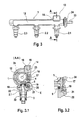
- FIG. 3 shows a fuel meter in longitudinal section with several injection valves integrated in it.
- the fuel distributor 1 which can be made of plastic, for example, contains a cavity 12 which can be filled with fuel via a connection 23 to a fuel reservoir (not shown here) or a fuel pump via an interposed filter element 24.
- the individual injection valves 2.1, 2.2 and 2.3 are supplied with fuel from the cavity 12 within the fuel distributor made of plastic.
- a central plug which consists of a plug component 13 on the housing side and a cover 14 covering it, is received on the fuel distributor 1 as shown in FIG. 3.
- Figure 3.1 shows a cross section through the fuel rail in the area of the injector 2.1 along the section line A-A.
- a central plug connection 15 is formed on the one hand by a central plug housing 13 and a cover element 14 which can be attached to it.
- a lead frame receptacle 16 extends from the central plug connection in the fuel distributor 1, in which a lead frame 17 for electrical contacting of the respective injection valve 2.1 or 2.2 or 2.3 is received.
- the lead frame 17 extends to the foot of the fuel distributor 1.
- the connection 23 can also be seen in the cross section according to the illustration in FIG.
- the reference element 24 in the illustration according to FIG. 3.1 denotes the filter element arranged between the fuel connection 23 and the cavity 12 of the fuel distributor 1.
- a cohesive connection 18 is formed along a specially designed connection geometry 20.
- the integral connection 18 can be produced, for example, by ultrasonic welding, for which purpose a special connection geometry of the fuel distributor 1 and the injection valve body 22 in the form of an annular projection 21 is to be provided.
- the injection valve 2.1 is electrically contacted by moving the lead frame 17 accommodated in the connector receptacle 16 into one another with the connector tabs 19 protruding from the injection valve body 22 (cf. detailed illustration in FIG. 3.2) ).
- the fuel entering via the connection 23 flows through the through bore 4 in the direction of the injection valve 2.1, wherein several injection valves 2.1 or 2.2 or 2.3 can be integrated into a fuel distributor 1 perpendicular to the plane of the drawing shown in FIG. 3.1 ,
- FIG. 3.2 shows the electrical contacting of the injection valve on an enlarged scale.
- connection geometry 20 contains an approximately annular projection 21. Above the annular projection 21, a plug tab 19 is provided.
- the lead frame 17 in the fuel distributor 1 comprises a plurality of conductor tracks, not shown here, which are each connected to the individual injection valves 2.1, 2.2 and 2.3, which are supplied via the fuel distributor 1 and which, on the other hand, all converge in the central plug connection 15 and via this centrally with one
- the harness of the internal combustion engine, not shown here, is connected.
- Figure 4 shows an injection valve which is integrated in the fuel rail.
- the injection valve 2.1 shown in FIG. 4 comprises a cavity 3, the injection valve body 22 being fastened along the connection geometry 20 to the foot of the fuel distributor 1.
- an annular recess is provided in the joining area on the injection valve body 22.
- the injection valve 22 can be sealed and in particular the permeation of fuel can be restricted.
- the lead frame 17 and the cable connection 25 of the injection valve 2.1 move together within a contacting recess 26, so that the lead frame 17 and the plug tab of the electrical connection 25 are in the area of one Connect contact point 27 and establish electrical contact.
- the contacting recess 26 is potted, so that the electrical connection is protected against external influences. Since a cohesively produced connection 18 is formed between the fuel distributor 1 and the injection valve body 22, the injection valve 2.1 can no longer be removed from the fuel distributor 1, and the electrical contact 27 by means of the lead frame 17 and the plug tab 19 can no longer be removed.
- FIG. 5 shows the production of a one-piece configured fuel distributor with insert modules.
- the injection valve 2.1 forms a preassembled module 38 on which electrical connections 25 are formed.
- the pre-assembled assembly 38 comprises a pre-molded part 33, to which a sealing ring 9 is fixed.
- the preassembled assembly 38 of the injection valve 2.1 is positioned on a complete encapsulation tool, as are the cores which form the cavity 12 of the fuel distributor at insertion positions 36 and the inlet to the injection valve 2.1 to be poured into the fuel distributor 30.
- the am Sealing ring 7 which is held by injection molded part 33, is also overmolded, so that on the one hand a cohesive receptacle of the injection valve 2.1 to be inserted into the injection mold as a preassembled assembly 38 and, on the other hand, the one-piece fuel distributor 30 is made directly by contacting the conductor tracks 32 with the electrical connecting lines 25 on the preassembled assembly 38 established.
- the holes required to pull the cores are filled with plugs.
- the functional group 38 of the injection valve 2.1 is contacted with the electrical conductor tracks 32 on the contact pins 25 before the encapsulation.
- the pre-assembled assembly 38 is then completely encapsulated by the injection mold.
- the injection mold is designed in such a way that the hydraulic contacting of the functional group 38 is ensured.
- additional valve slides are required, which are guided perpendicular to the main slide, with which the cavity 12 of the fuel distributor 30 is created.
- the openings at the top of the fuel distributor 30, which are used to remove the cores which are used to manufacture the cavities 36 in the one-piece fuel distributor 30 to be provided for the injection valves 2.1, are then closed.
- FIG. 6 shows a perspective view of a one-piece fuel distributor 30, in which an injection valve 2.1 designed as a preassembled assembly 38 is integrally molded.
- a central plug connection 15 is formed on the top of the one-piece fuel distributor 30, which comprises a plug housing 13 on the one hand and a cover 14 shielding it on the other hand.
- Reference number 34 denotes a connection to a fuel source, not shown here.
- the combination of the individual contacts previously provided for the individual injectors to form a central plug means that separate sub-wiring harnesses for the individual injectors can be dispensed with, and assembly steps and individual parts can be saved.
- the cover element 14 provided on the central plug 15 better protects the electrical contacts, in particular against mechanical and climatic influences which act from the outside.
Applications Claiming Priority (2)
| Application Number | Priority Date | Filing Date | Title |
|---|---|---|---|
| DE10136050 | 2001-07-25 | ||
| DE10136050A DE10136050A1 (de) | 2001-07-25 | 2001-07-25 | Verfahren zur Herstellung eines Kraftstoffzuteilers mit integrierten Einspritzventilen |
Publications (3)
| Publication Number | Publication Date |
|---|---|
| EP1279825A2 true EP1279825A2 (fr) | 2003-01-29 |
| EP1279825A3 EP1279825A3 (fr) | 2003-04-09 |
| EP1279825B1 EP1279825B1 (fr) | 2005-04-06 |
Family
ID=7692925
Family Applications (1)
| Application Number | Title | Priority Date | Filing Date |
|---|---|---|---|
| EP02012140A Expired - Lifetime EP1279825B1 (fr) | 2001-07-25 | 2002-06-01 | Méthode de fabrication d'un distributeur de carburant avec injecteurs intégrés |
Country Status (4)
| Country | Link |
|---|---|
| US (1) | US6860008B2 (fr) |
| EP (1) | EP1279825B1 (fr) |
| JP (1) | JP2003129917A (fr) |
| DE (2) | DE10136050A1 (fr) |
Cited By (5)
| Publication number | Priority date | Publication date | Assignee | Title |
|---|---|---|---|---|
| EP2093413A1 (fr) | 2008-02-19 | 2009-08-26 | Continental Automotive GmbH | Dispositif de couplage |
| EP2208883A1 (fr) | 2009-01-19 | 2010-07-21 | Continental Automotive GmbH | Dispositif de couplage |
| US7934488B2 (en) | 2008-02-19 | 2011-05-03 | Continental Automotive Gmbh | Coupling device |
| US7976073B2 (en) | 2008-02-19 | 2011-07-12 | Continental Automotive Gmbh | Coupling device |
| US8286612B2 (en) | 2008-02-19 | 2012-10-16 | Continental Automotive Gmbh | Coupling device |
Families Citing this family (7)
| Publication number | Priority date | Publication date | Assignee | Title |
|---|---|---|---|---|
| DE10333721B4 (de) * | 2003-07-23 | 2005-07-07 | Benteler Automobiltechnik Gmbh | Kraftstoffverteilerleiste mit einem Anschlussstück |
| DE10341501A1 (de) * | 2003-09-05 | 2005-03-31 | Robert Bosch Gmbh | Verfahren zur Herstellung von Kunststoffteilen mit integrierten Leiterbahnen |
| US7028668B1 (en) | 2004-12-21 | 2006-04-18 | Robert Bosch Gmbh | Self-damping fuel rail |
| JP4527761B2 (ja) * | 2007-10-30 | 2010-08-18 | 三菱電機株式会社 | 燃料噴射弁およびその製造方法 |
| BRPI1005341B1 (pt) * | 2010-12-02 | 2016-12-20 | Bosch Do Brasil | galeria de combustível de material plástico com sistema de aquecimento |
| DE102011078734A1 (de) * | 2011-07-06 | 2013-01-10 | Robert Bosch Gmbh | Komponente eines Brennstoffeinspritzsystems und Brennstoffeinspritzsystem |
| DE102019200037A1 (de) * | 2019-01-04 | 2020-07-09 | Robert Bosch Gmbh | Einrichtung zur elektrischen Verbindung eines Steuerkabels mit mehreren Einspritzventilen |
Citations (4)
| Publication number | Priority date | Publication date | Assignee | Title |
|---|---|---|---|---|
| DE4325980A1 (de) * | 1993-08-03 | 1995-02-09 | Bosch Gmbh Robert | Vorrichtung zur gemeinsamen elektrischen Kontaktierung mehrerer elektrisch erregbarer Aggregate von Brennkraftmaschinen |
| DE19546441A1 (de) * | 1995-12-13 | 1997-06-19 | Bosch Gmbh Robert | Brennstoffverteiler |
| DE19757347A1 (de) * | 1996-12-24 | 1998-06-25 | Toyota Motor Co Ltd | Kraftstoffeinspritzvorrichtung |
| WO1999040315A1 (fr) * | 1998-02-05 | 1999-08-12 | Siemens Automotive Corporation | Douille non magnetique pour injecteur de carburant soude |
Family Cites Families (2)
| Publication number | Priority date | Publication date | Assignee | Title |
|---|---|---|---|---|
| JPH08200182A (ja) * | 1995-01-25 | 1996-08-06 | Zexel Corp | 電磁式燃料噴射弁およびその取付け構造 |
| US5718206A (en) * | 1995-10-12 | 1998-02-17 | Nippondenso Co., Ltd. | Fuel supply system having fuel rail |
-
2001
- 2001-07-25 DE DE10136050A patent/DE10136050A1/de not_active Withdrawn
-
2002
- 2002-06-01 DE DE50202694T patent/DE50202694D1/de not_active Expired - Lifetime
- 2002-06-01 EP EP02012140A patent/EP1279825B1/fr not_active Expired - Lifetime
- 2002-07-23 JP JP2002214128A patent/JP2003129917A/ja active Pending
- 2002-07-24 US US10/200,976 patent/US6860008B2/en not_active Expired - Fee Related
Patent Citations (4)
| Publication number | Priority date | Publication date | Assignee | Title |
|---|---|---|---|---|
| DE4325980A1 (de) * | 1993-08-03 | 1995-02-09 | Bosch Gmbh Robert | Vorrichtung zur gemeinsamen elektrischen Kontaktierung mehrerer elektrisch erregbarer Aggregate von Brennkraftmaschinen |
| DE19546441A1 (de) * | 1995-12-13 | 1997-06-19 | Bosch Gmbh Robert | Brennstoffverteiler |
| DE19757347A1 (de) * | 1996-12-24 | 1998-06-25 | Toyota Motor Co Ltd | Kraftstoffeinspritzvorrichtung |
| WO1999040315A1 (fr) * | 1998-02-05 | 1999-08-12 | Siemens Automotive Corporation | Douille non magnetique pour injecteur de carburant soude |
Cited By (6)
| Publication number | Priority date | Publication date | Assignee | Title |
|---|---|---|---|---|
| EP2093413A1 (fr) | 2008-02-19 | 2009-08-26 | Continental Automotive GmbH | Dispositif de couplage |
| US7934488B2 (en) | 2008-02-19 | 2011-05-03 | Continental Automotive Gmbh | Coupling device |
| US7976073B2 (en) | 2008-02-19 | 2011-07-12 | Continental Automotive Gmbh | Coupling device |
| US8286612B2 (en) | 2008-02-19 | 2012-10-16 | Continental Automotive Gmbh | Coupling device |
| EP2208883A1 (fr) | 2009-01-19 | 2010-07-21 | Continental Automotive GmbH | Dispositif de couplage |
| US8245697B2 (en) | 2009-01-19 | 2012-08-21 | Continental Automotive Gmbh | Coupling device |
Also Published As
| Publication number | Publication date |
|---|---|
| DE10136050A1 (de) | 2003-02-13 |
| US20030019477A1 (en) | 2003-01-30 |
| US6860008B2 (en) | 2005-03-01 |
| EP1279825B1 (fr) | 2005-04-06 |
| JP2003129917A (ja) | 2003-05-08 |
| EP1279825A3 (fr) | 2003-04-09 |
| DE50202694D1 (de) | 2005-05-12 |
Similar Documents
| Publication | Publication Date | Title |
|---|---|---|
| EP0862689B1 (fr) | Distributeur de carburant | |
| DE19936300A1 (de) | Druckerkennungsvorrichtung, Verbindungsteil hierfür, sowie Verfahren zur Herstellung eines elektrischen Bauteileverbinders | |
| EP1279825A2 (fr) | Méthode de fabrication d'un distributeur de carburant avec injecteurs intégrés | |
| DE102005009441A1 (de) | Steckverbinder mit einer Crimp-Abdichtung und/oder einer Kabelhalterung | |
| EP2122784B1 (fr) | Ensemble capteur | |
| DE112006003140T5 (de) | Verbindungsteil und Kabelbaum, der dasselbe verwendet | |
| DE102010016298A1 (de) | Kraftstoffeinspritzvorrichtung mit Kraftstoffdrucksensor und Verfahren zu ihrer elektrischen Verbindung | |
| DE4328089C2 (de) | Verfahren zum Herstellen einer Zündspuleneinheit für einen Verbrennungsmotor sowie nach diesem Verfahren hergestellte Zündspuleneinheit | |
| DE4336455A1 (de) | Zündanlage mit Zündfunkenverteilerkassette und Zündspule | |
| EP1920506B1 (fr) | Connecteur electrique et son procede de production | |
| EP3622589B1 (fr) | Module électronique et procédé de fabrication | |
| EP0888705B1 (fr) | Appareil electrique | |
| DE19844742C1 (de) | Piezoaktorkontaktierung für Einspritzventil | |
| DE19940346B4 (de) | Piezoaktor mit einer Anschlußvorrichtung | |
| DE19804607C2 (de) | Anordnung zum elektrischen Anschluß zumindest eines Sensors | |
| DE2702405A1 (de) | Elektrisches kraftstoffoerderaggregat | |
| WO2004047191A2 (fr) | Metallisation d'actionneur piezo-electrique destinee a une soupape d'injection et procede de fabrication | |
| DE102004058715B4 (de) | Kraftstoffinjektor für eine Brennkraftmaschine sowie Verfahren zur Herstellung eines Kraftstoffinjektors | |
| DE102012102634A1 (de) | Elektronische Komponenten-Vorrichtung | |
| EP2636082B1 (fr) | Procédé de production d'une unité actionneur avec douille destinée à recevoir un actionneur piézoélectrique | |
| DE4108416A1 (de) | Kraftstoff-einspritzduese fuer brennkraftmaschinen | |
| DE10206908B4 (de) | Injektor mit verbesserter Anschlussgeometrie | |
| DE102006041641B4 (de) | Gehäuse für ein Funktionsmodul sowie Verfahren zur Herstellung des Gehäuses | |
| DE102017216533A1 (de) | Halter für eine Sensoreinheit | |
| DE102015226339A1 (de) | Saugrohranordnung einer Brennkraftmaschine |
Legal Events
| Date | Code | Title | Description |
|---|---|---|---|
| PUAI | Public reference made under article 153(3) epc to a published international application that has entered the european phase |
Free format text: ORIGINAL CODE: 0009012 |
|
| AK | Designated contracting states |
Designated state(s): AT BE CH CY DE DK ES FI FR GB GR IE IT LI LU MC NL PT SE TR |
|
| AX | Request for extension of the european patent |
Extension state: AL LT LV MK RO SI |
|
| PUAL | Search report despatched |
Free format text: ORIGINAL CODE: 0009013 |
|
| AK | Designated contracting states |
Kind code of ref document: A3 Designated state(s): AT BE CH CY DE DK ES FI FR GB GR IE IT LI LU MC NL PT SE TR |
|
| AX | Request for extension of the european patent |
Extension state: AL LT LV MK RO SI |
|
| RIC1 | Information provided on ipc code assigned before grant |
Ipc: 7F 02M 51/00 A Ipc: 7F 02M 55/00 B |
|
| 17P | Request for examination filed |
Effective date: 20031009 |
|
| 17Q | First examination report despatched |
Effective date: 20031113 |
|
| AKX | Designation fees paid |
Designated state(s): DE FR GB IT SE |
|
| GRAP | Despatch of communication of intention to grant a patent |
Free format text: ORIGINAL CODE: EPIDOSNIGR1 |
|
| GRAS | Grant fee paid |
Free format text: ORIGINAL CODE: EPIDOSNIGR3 |
|
| GRAA | (expected) grant |
Free format text: ORIGINAL CODE: 0009210 |
|
| AK | Designated contracting states |
Kind code of ref document: B1 Designated state(s): DE FR GB IT SE |
|
| PG25 | Lapsed in a contracting state [announced via postgrant information from national office to epo] |
Ref country code: IT Free format text: LAPSE BECAUSE OF FAILURE TO SUBMIT A TRANSLATION OF THE DESCRIPTION OR TO PAY THE FEE WITHIN THE PRESCRIBED TIME-LIMIT;WARNING: LAPSES OF ITALIAN PATENTS WITH EFFECTIVE DATE BEFORE 2007 MAY HAVE OCCURRED AT ANY TIME BEFORE 2007. THE CORRECT EFFECTIVE DATE MAY BE DIFFERENT FROM THE ONE RECORDED. Effective date: 20050406 Ref country code: GB Free format text: LAPSE BECAUSE OF FAILURE TO SUBMIT A TRANSLATION OF THE DESCRIPTION OR TO PAY THE FEE WITHIN THE PRESCRIBED TIME-LIMIT Effective date: 20050406 |
|
| REG | Reference to a national code |
Ref country code: GB Ref legal event code: FG4D Free format text: NOT ENGLISH |
|
| REG | Reference to a national code |
Ref country code: IE Ref legal event code: FG4D Free format text: LANGUAGE OF EP DOCUMENT: GERMAN |
|
| REF | Corresponds to: |
Ref document number: 50202694 Country of ref document: DE Date of ref document: 20050512 Kind code of ref document: P |
|
| PG25 | Lapsed in a contracting state [announced via postgrant information from national office to epo] |
Ref country code: SE Free format text: LAPSE BECAUSE OF FAILURE TO SUBMIT A TRANSLATION OF THE DESCRIPTION OR TO PAY THE FEE WITHIN THE PRESCRIBED TIME-LIMIT Effective date: 20050706 |
|
| GBV | Gb: ep patent (uk) treated as always having been void in accordance with gb section 77(7)/1977 [no translation filed] |
Effective date: 20050406 |
|
| PLBE | No opposition filed within time limit |
Free format text: ORIGINAL CODE: 0009261 |
|
| STAA | Information on the status of an ep patent application or granted ep patent |
Free format text: STATUS: NO OPPOSITION FILED WITHIN TIME LIMIT |
|
| ET | Fr: translation filed | ||
| 26N | No opposition filed |
Effective date: 20060110 |
|
| PGFP | Annual fee paid to national office [announced via postgrant information from national office to epo] |
Ref country code: DE Payment date: 20130828 Year of fee payment: 12 |
|
| PGFP | Annual fee paid to national office [announced via postgrant information from national office to epo] |
Ref country code: FR Payment date: 20140617 Year of fee payment: 13 |
|
| REG | Reference to a national code |
Ref country code: DE Ref legal event code: R119 Ref document number: 50202694 Country of ref document: DE |
|
| REG | Reference to a national code |
Ref country code: DE Ref legal event code: R119 Ref document number: 50202694 Country of ref document: DE Effective date: 20150101 |
|
| PG25 | Lapsed in a contracting state [announced via postgrant information from national office to epo] |
Ref country code: DE Free format text: LAPSE BECAUSE OF NON-PAYMENT OF DUE FEES Effective date: 20150101 |
|
| REG | Reference to a national code |
Ref country code: FR Ref legal event code: ST Effective date: 20160229 |
|
| PG25 | Lapsed in a contracting state [announced via postgrant information from national office to epo] |
Ref country code: FR Free format text: LAPSE BECAUSE OF NON-PAYMENT OF DUE FEES Effective date: 20150630 |