EP1278554B1 - Lichtdurchlässiger förderer zur verwendung bei der sterilisierung mit gepulstem licht - Google Patents
Lichtdurchlässiger förderer zur verwendung bei der sterilisierung mit gepulstem licht Download PDFInfo
- Publication number
- EP1278554B1 EP1278554B1 EP01932605A EP01932605A EP1278554B1 EP 1278554 B1 EP1278554 B1 EP 1278554B1 EP 01932605 A EP01932605 A EP 01932605A EP 01932605 A EP01932605 A EP 01932605A EP 1278554 B1 EP1278554 B1 EP 1278554B1
- Authority
- EP
- European Patent Office
- Prior art keywords
- transmissive
- target object
- treatment zone
- light
- pulsed
- Prior art date
- Legal status (The legal status is an assumption and is not a legal conclusion. Google has not performed a legal analysis and makes no representation as to the accuracy of the status listed.)
- Expired - Lifetime
Links
Images

Classifications
-
- A—HUMAN NECESSITIES
- A61—MEDICAL OR VETERINARY SCIENCE; HYGIENE
- A61L—METHODS OR APPARATUS FOR STERILISING MATERIALS OR OBJECTS IN GENERAL; DISINFECTION, STERILISATION OR DEODORISATION OF AIR; CHEMICAL ASPECTS OF BANDAGES, DRESSINGS, ABSORBENT PADS OR SURGICAL ARTICLES; MATERIALS FOR BANDAGES, DRESSINGS, ABSORBENT PADS OR SURGICAL ARTICLES
- A61L2/00—Disinfection or sterilisation of materials or objects, in general; Accessories therefor
- A61L2/02—Disinfection or sterilisation of materials or objects, in general; Accessories therefor using physical processes
- A61L2/08—Radiation
- A61L2/10—Ultraviolet [UV] radiation
Definitions
- the present invention relates to sterilization of products, and more particularly to sterilization of products using pulsed, short duration, polychromatic, incoherent light. Even more particularly, the present invention relates to sterilization of products wherein a transmissive carrier is employed to transport the product through a treatment zone thereby permitting complete sterilization of the product by avoiding shadowing of the pulsed polychromatic incoherent light.
- the present invention addresses the particular need which exists for improved methods and apparatus for efficiently sterilizing or reducing the microbiological burden on the surfaces of or throughout the volume of anything requiring sterilization.
- surfaces and volumes of products needing sterilization include surfaces of solids and/or solids within liquid products, surfaces or volumes of food stuffs, surfaces or volumes of containers for food stuffs, surfaces of medical devices, surfaces of packages, and volumes of liquids.
- any varieties of foods such as fresh fish
- medical products have a relatively limited storage time before being subject to microbial and/or enzymatic spoilage, which limits the distribution and marketing.
- microbial deactivation must be achieved to medically acceptable sterility levels.
- Improved methods and apparatus suitable for extending the shelf life of perishable foods, medical devices and any other products requiring sterilization are therefore desirable.
- An improved apparatus and method for sterilization of non-food products such as medical devices is particularly desirable for research apparatus such as chemical reagents, plates, and test tubes which must be sterile to be used in unlimited medical or research procedures.
- pulsed light for sterilization of a product surface (typically meaning an exterior solid surface thickness to about 0.1 mm) is only as effective as the ability of the pulsed light to penetrate through any obstructions to the surfaces or volumes to be sterilized, that is, all areas to be treated must be fully contacted by the sterilizing levels of light.
- the target object is a fluid
- a fluid having a higher degree of transparency to a broad range of wavelengths such as water and air
- the target object will be more effectively treated by a given level of light than a more opaque fluid such as wine or sugar solution.
- a more opaque fluid solution would require either a smaller treating volume or a higher level of light, both of which reduce efficiency and in the later case, risk damage to the target object by the sterilizing level of light.
- the target object is a solid object or material, such as a food product or medical device, the solid object must be contacted by the pulsed light sufficiently, on all surfaces, to be sterilized, without shadowing of any such surfaces.
- the '559 patent teaches that such an object may be treated by rotating or turning the object during a multiple exposure treatment involving a series of light pulses; or by letting the object freely fall through a treatment zone surrounded by flashlamps so that substantially the entire surface of the product is subjected to simultaneous treatment.
- the '559 patent also teaches that the solid object or material may be packaged in a transparent wrapping material prior to the pulsed light treatment, to reduce the shadowing effect as compared to a more opaque wrapping material used around the solid object.
- U.S. Patent No. 5,489,442 (hereinafter the '442 patent, issued February 6, 1996 to Dunn, et. al.), similarly teaches methods for treatment of solid objects.
- the '442 patent describes the use of rollers or shakers to rotate the product between two or more flashes, or that the product may be rotated manually.
- the present application discloses a method and apparatus for sterilizing a product with pulsed light while mitigating against shadowing of the pulsed light upon the product being sterilized.
- US-A-5,958,336 discloses an apparatus for sterilizing a target using a plurality of light sources.
- the present invention is defined in claim 1.
- the following description discloses an apparatus for transporting a target object within a pulsed light sterilization chamber via a transmissive carrier which allows for sterilization of the target object without obstruction or shadowing by the transmissive carrier.
- the description also discloses a system for sterilizing the target object using such transmissive carrier to transport the target object through the system.
- One embodiment disclosed is an apparatus for carrying a target object having a surface, within a pulsed light sterilization chamber within which pulsed sterilizing light is emitted.
- the apparatus comprises: a transmissive carrier within the treatment zone, the transmissive carrier engaging the target object, the transmissive carrier having a transmissivity of at least about 10% between 250 and 350 nm wavelength; and moving means coupled to the transmissive carrier for moving the target object by moving the transmissive carrier through the treatment zone, the surface being sterilized by the pulsed sterilizing light, at least a portion of the pulsed sterilizing light passing through the transmissive carrier before reaching the target object.
- Another embodiment is a system for sterilizing a target object having a surface.
- the system comprises: a pulsed light sterilization chamber comprising a treatment zone and means for emitting pulsed sterilizing light within the treatment zone; a moving means; and a transmissive carrier within the treatment zone, the transmissive carrier engaging the target object, and being coupled to the moving means, the moving means moving the target object by moving the transmissive carrier through the treatment zone such that the surface of the target object is sterilized by the pulsed light in the treatment zone, at least a portion of the pulsed light passing through the transmissive carrier before reaching the target object.
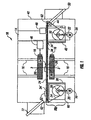
- a pulsed light sterilization system 10 is shown, in accordance herewith, that employs one embodiment of a transmissive carrier for carrying a target object 52 through a pulsed light treatment chamber 14.
- the pulsed light sterilization system 10 comprises: an entrance drop 12 with a flap (not shown); the pulsed light sterilization chamber 14; a flashlamp unit 26 comprising a plurality of flashlamps (and reflectors as shown later in FIG. 3); a plurality of flashlamp supports 16; an electronic interface 18 for each flashlamp unit 26; an initial wheel 20; a take-up wheel 22; a thin film 24; a first rolled portion 28 of the thin film 24; a moving mechanism (or moving means) 30; a second rolled portion 32 of the thin film 24; a slide deck 34; a transmissive support 36; an initial wheel shielding 38; a take-up wheel shielding 40; reflective walls 42; a shaft encoder 44, a pulser 46 (with a programmable logic controller, PLC), a packager 48; and an exit drop 50.
- PLC programmable logic controller
- the entrance drop 12 comprises an entrance drop, including an entrance slide, connecting an outside environment to an interior of the pulsed light sterilization chamber 14.
- the entrance drop 12 further comprises a door or flap to the pulsed light sterilization chamber 14, through which the target object 52 must pass.
- the door or flap rests horizontally when closed and covers an upper side of the entrance drop 12, above the entrance slide.
- the entrance drop 12, together with the door or flap, encases the entrance slide and forms a light-tight entry into the pulsed light sterilization chamber 14.
- the pulsed light sterilization chamber 14 may preferably be enclosed by reflective walls 42, also contributing to the light-tight structure of the pulsed light treatment chamber.
- the pulsed light sterilization chamber 14 includes a treatment zone 54 for pulsed light sterilization of the target object 52 and a transport system 58 (comprising the thin film 24, the initial wheel 20, the take-up wheel 22, and the moving means 30) for transporting the target object 52 through the pulsed light sterilization chamber 14, into and out of the treatment zone 54.
- the treatment zone 54 preferably lies in a region surrounded by a plurality of sterilizing light sources, such as the plurality of flashlamps within the flashlamp units 26.
- the flashlamp unit 26 includes a plurality concave reflectors (shown later in FIG. 3) each comprising an elongated trough having a curved cross-section, such as in the shape of a half ellipse, a parabola, a hyperbola or a similar curved shape.
- Each concave reflector contains at least one flashlamp (shown later in FIG. 3) positioned parallel to the concave reflectors's major axis (horizontal and parallel to the paper in FIG. 1).
- Each flashlamp radiates pulsed light from a position roughly equidistant from the target object 52, so that an approximately homogeneous light intensity can be maintained over a plurality of surfaces of the target object 52.
- Shaping the reflectors can also be customized to help accomplish homogeneous intensity.
- the flashlamps themselves can also take any of a variety of geometries or configurations, such as "U" shaped flashlamps, tubular (or linear) flashlamps or any combination of the above geometries or other geometries also known in the flashlamp art.
- An assortment of styles of such flashlamps may be obtained from PurePulse Technologies, Inc., located in San Diego, California.
- a pulsed light unit such as PUREBRIGHT PBS-1, available from PurePulse Technologies, Inc. of San Diego, California may be used to generate intense, short duration pulses of broad spectrum polychromatic incoherent light such as may be used by the sterilization chamber of FIGS. 1, 2 or 3.
- the pulsed light unit such as the PUREBRIGHT system cited above, includes a pulsing device 46, with a DC power supply that charges energy storage capacitors ; a switch used to discharge the capacitors; a trigger circuit used to fire the switch at pre-programmed time intervals, in response to sensors that detect the position of the target object 52 to be treated, or in response to a button being depressed; and a set of high voltage coaxial cables carrying the discharged pulses from a capacitor-switch assembly to the flashlamps.
- the flashlamp units 26 optionally include from one to eight flashlamps mounted in metal reflectors so as to direct the polychromatic light emitted from the flashlamps toward the target object 52.
- pulsed light unit and flashlamp unit 26 are also conceivable within the scope and principles of the present embodiment wherein a variety of light intensities or amount of total sterilizing pulses may be required.
- one other preferred embodiment employs swivelable flashlamp units.
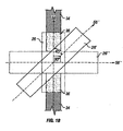
- FIG. 1B a top planar view is illustrated of one preferred embodiment of the flashlamp units 26, wherein the flashlamp units 26 may be swivelled within a plane parallel to the direction of travel of the target object as it traverses the treatment zone and thereby can be adjusted to a particular angle with respect to a major axis of the flashlamp units 26 as shown in FIG. 1.
- the ability to swivel the flashlamp units 26 allows the user to adjust an amount of pulsed light which is incident upon the target object 52 throughout its passage within the treatment zone 54, as well as an energy density (J/cm 2 ) deposited on the plurality of surfaces of the target object 52 by the pulsed light. In this manner, a total amount of sterilization through the treatment zone 54 may be adjusted without having to modify speed of the conveyor (e.g., the thin film 24) or parameters of the pulser 46 (such as pulse duration, intensity of each pulse, or number of pulses, etc).
- the flashlamp unit 26 is moved from its original position for maximum light incidence (as in FIG. 1), wherein the flashlamp unit 26 has a major axis 56 lying coincidentally in a direction of a first major axis 56 of the transmissive support 36 and of the slide deck 34, to an intermediary position for moderate light incidence, shown by a flashlamp unit 26', wherein the flashlamp unit 26' has a second major axis 56' lying 45° from the first major axis 56'.
- the flashlamp unit 26' may be moved into position shown by a flashlamp unit 26" such that it has a third major axis 56" lying 90° from the first major axis 56 and 45° from the second major axis 56'.
- the flashlamp units 26 are each coupled to the pulser 46 and the electronic interface 18 is coupled to each of the flashlamp units 26 for sending control signals (for controlling the pulsed sterilized light and position of the flashlamp units 26) to the flashlamp units 26 from the pulser 46.
- a shaft encoder 44 may optionally be coupled to one of the rollers 62 to measure a rotational speed of the rollers 62.
- the shaft encoder 44 sends out a pulse train to the pulser 46, whose frequency is an indication of the rotational speed of the roller 62 to which it is coupled.
- the pulser 46 flashes the lamps and starts counting again until a next flash is generated after another predetermined number of pulses, and so forth.
- the rollers 62 rotate as the thin film 24 is pulled by the take-up wheel 22, which rotates in response to the moving mechanism 30.
- the moving mechanism 30 may be a rotation device, such as a spinning shaft, belt gear, chain or other linkage coupled to a motor, that is rotatably coupleable with the initial and take-up wheels 20, 22.
- the moving mechanism 30 may be rotatably coupled to the take-up wheel 22, so as to allow forward rotation of the initial wheel 20 and the take-up wheel 22.
- the moving mechanism 30 is rotatably coupled to both the initial wheel 20 and the take-up wheel 22 so as to enable controlled rotation of the thin film 24 in either direction and from either of the initial wheel 20 and the take-up wheel 22 to the other.
- the moving mechanism 30 rotates the take-up wheel 22 clockwise to spool the thin film 24 from the initial wheel 20, causing the initial wheel 20 to rotate clockwise as well, thereby causing the thin film 24 to move from a left side to a right side of the system as shown in FIG 1.
- the moving mechanism 30 rotates the initial wheel 20 counter-clockwise to respool the initial wheel 20 for re-use.
- the thin film 24 is used as a transmissive carrier for carrying the target object 52 through the treatment zone 54 while simultaneously avoiding shadowing on the target object 52 from the pulsed light emitted by the flashlamp units 26.
- the thin film 24 is a transmissive film which preferably has a transmissivity (defined as total throughput of light within a prescribed bandwidth of light) of at least over 10% in a 250 nm to 350 nm wavelength range and more preferably maintains at least this level of transmissivity through at least one or more, e.g., more than five or ten, e.g., more than twenty sterilization treatments comprising, e. g. , at least 1 flash at 300 ⁇ s/flash of broad-spectrum polychromatic light having at least a 0.25 J/cm 2 corresponding energy density at a 170-2600 nm broadband bandwidth within the treatment zone.
- a transmissivity defined as total throughput of light within a prescribed bandwidth of light
- the thin film 24 is sufficiently heat tolerant and ultraviolet tolerant to maintain its level of transmissivity through at least one sterilization treatment, and preferably through several sterilization treatments. This is an important feature of the thin film 24 as it is susceptible to degradation with prolonged exposure to the pulsed light.
- the thin film 24, made from any polyethylene, polypropylene, nylon, or aclar, and that is less than about 1.27x10 -4 m (5 mils) thick, will degrade by about 5% after being exposed to about 20 flashes of the 300 ⁇ s/flash broadband polychromatic light of the corresponding energy density equal to at least 2 J/cm 2 at its plurality of surfaces at 170-2600 nm broadband bandwidth.
- the thin film. 24 may be re-used, if not too degraded for the particular application.
- the initial wheel 20 can be respooled as described above, by pulling the thin film 24 from the second rolled portion 32 to the first rolled portion 28.
- the user may replace the thin film 24 by placing a new first rolled portion 28 upon the initial wheel 20 and threading it attachably to the take-up wheel 22.
- an entire new tape cassette 60 comprising both the initial wheel 20 and the take-up wheel 22 may be employed by threading the thin film 24 around rollers 62 and the slide deck 34 and transmissive support 36 in a manner somewhat (but not exactly) akin to a music tape cassette threaded through a tape player. This allows for increased versatility in how the thin film 24 can be employed.
- the thin film 24 may be made of various materials, well known to those of skill in the art, tending to be transmissive in the UV and visible part of the spectrum. As described earlier, some materials having this property which can be used in the thin film 24 include, but are not limited to: polyethylene, polypropylene, nylon and aclar.
- the thin film 24 material and thickness selected is durable enough to withstand a weight of the target object 52 and frictional forces experienced in transporting the target object 52 through the sterilization chamber 14, yet is flexible enough to easily wind around the initial wheel 20 and the take-up wheel 22 and is thin enough to minimize interference with the sterilizing light.
- the thin film 24 preferably has a thickness of less than about 5 mils and most preferably is about 2.54x10 -5 to 5.08x10 -5 m (1 to 2 mils) in thickness and may be made of any of the above listed materials.
- the thin film 24 is placed in a configuration such that it is used as a conveyor belt, transporting the target object 52 through the treatment zone 54, wherein the thin film 24 includes the first rolled portion 28 rolled upon the initial wheel 20, and the second rolled portion 32 rolled upon the take-up wheel 22. In this way the thin film 24 is spooled from the first rolled portion 28 to the second rolled portion 32.
- Shielding can substantially enclose one or both of the initial or take-up wheels 20, 22, or just intercept radiation from a portion of a surrounding volume around one or both of the initial or take-up wheels 20, 22.
- the thin film 24 of the present embodiment preferably extends from between the first rolled portion 28 and the second rolled portion 32 spanning from underneath the entrance drop 12, across the treatment zone 54, and to the exit drop 50.
- the slide deck 34 is positioned below the thin film 24 thereby giving support to the thin film 24.
- the slide deck 34 comprises two deck portions for supporting and conveying the thin film 24 to and from the treatment zone 54, so that the thin film 24 maintains its strength and ability to transport the target object 52 to the treatment zone 54.
- An entrance deck portion 34' of the slide deck 34 extends from below the entrance drop 12 and abuts the transmissive support 36.
- An exit deck portion 34" of the slide deck 34 extends from the transmissive support 36 to above an exit drop 50.
- the transmissive support 36 is coupled on one side to the entrance deck portion 34' and on an opposing side to the exit deck portion 34".
- the transmissive support 36 spans a length of the treatment zone 54 and is positioned between the two flashlamp units 26 such that the pulsed sterilizing light from the flashlamp units is not shadowed in the treatment zone 54.
- the transmissive support 36 may be positioned any distance from each of the two flashlamp units 26, depending upon the required application for sterilization and the target object 52 being sterilized.
- the transmissive support 36 is positioned such that the intensity of light at upper and lower surfaces of the target object 52 is approximately equal, e.g., the transmissive support 36 may be positioned such that the target object 52 is approximately equidistant from each of the two flashlamp units 26.
- the transport system 56 moves the thin film 24 through the pulsed light sterilization system 10 by the moving mechanism 30.
- the moving mechanism 30, which may be a rotating pin belt, or shaft with motor, is coupled to the take-up wheel 22 or to both the initial wheel 20 and take-up wheel 22, depending upon the type of application and the requirement for reusing the thin film 24, and imparts a rotational force to the initial wheel 20 or the take-up wheel 22, thereby winding the thin film 24 onto the initial wheel 20 or the take-up wheel 22 (and thus off of the other of the initial wheel 20 and the take-up wheel 22) so as to move the thin film 24 through the treatment zone 54, across the slide deck 34 and the transmissive support 36.
- the first rolled portion 28 on the initial wheel 20 is moved from the first rolled portion 28 to the underneath of the entrance drop 12, then moved across the entrance deck portion 34', across the transmissive support 36, across the exit deck portion 34" to over the exit drop 50, and to the second rolled portion 32 on the take-up wheel 22.
- thin film 24 from the second rolled portion 32 is moved to underneath the exit drop 50, then across the exit deck portion 34", across the transmissive support 36, across the entrance deck portion 34' to under the entrance drop 12 to the first rolled portion 28.
- the target object 52 is dropped through the entrance drop 12 and falls onto the thin film 24 passing over the entrance deck portion 34' underneath the entrance drop 12.
- the target object 52 is conveyed or moved by the thin film 24 as the thin film 24 is moved into the treatment zone 54.
- the target object 52 is exposed to one or more pulses of high intensity, short-duration polychromatic light from the flashlamp units 26 and then continues moving on the thin film 24.
- the transmissive support 36 supports a weight of the target object 52 on the thin film 24 and allows the thin film 24 to slide thereon.
- the flashlamp units 26 operate according to a programmable logic controller (PLC) (not shown), inside the pulser 46 and electronic interfaces 18.
- PLC programmable logic controller
- the PLC stores user-defined parameters that define the operation of the flashlamps.
- the user-defined parameters pertain to several parametric conditions for operating the flashlamp units 26 which control how much pulsed light sterilization to apply and how, and, optionally, whether to rotate the flashlamp units 26 and by what angle of rotation.
- Examples of some of the user-defined parameters include: 1) charge voltage; 2) a number of pulses; 3) an energy density (e.g., in Joules/cm 2 ) deposited by the pulsed light; and 3) a set speed of the target object 52 through the treatment zone 54.
- the flashlamp units 26 operate to emit pulsed polychromatic, incoherent light with the following parameters or characteristics known to have good sterilizing effects. From 1 to 20 pulses of polychromatic incoherent light are emitted by the flashlamp units 26 during a transit of the target object 52 across the transmissive carrier. Generally, the pulses of polychromatic incoherent light are in a broad spectrum from 170 nm to 2600 nm using short pulses of durations from 0.001 to 100 milliseconds, at a high intensity, e.g., corresponding to an energy density of from 0.01 to 5 Joules/cm 2 at a surface of the target object 52.
- a monochromatic (e.g., laser) light source that is either pulsed or continuous, may be used.
- a polychromatic or monochromatic (e.g., laser) source that is either pulsed or continuous, may be used.
- a polychromatic or monochromatic (e.g. laser) source may be used for an extended period of time if more sterilization is needed, and depending upon the intensity of the pulsed light.
- Examples of extended durations of time which may be used in conjunction with the above parameters known for good sterilizing effects (170-2600 nm with pulses from .001 to 100 milliseconds with corresponding energy density of about 0.01 to 5 J/cm 2 ) for certain applications include periods of time lasting more than one (1) second, ten (10) seconds or several minutes even. A narrower spectrum may also be used, alternatively. For example, a pulse duration of 1/10 seconds for one second long would allow ten continuous total pules, if pulsed without time lapses between pulses, to be administered to the target object 52.
- the target object 52 may be wrapped in sterile wrap or packaged before it exits through the exit drop via the packager 48.
- FIG. 2 a partial cross-sectional side view is shown of different sections of the pulsed light sterilization chamber 14 of the pulsed light sterilization system of FIG. 1 near the treatment zone 54.
- a portion of the entrance deck portion 34' of the slide deck 34 comprises two layers, a substrate 102, and a Teflon coating 104.
- the thin film 24 is also shown as it slides on top of the entrance deck portion 34' as it approaches the treatment zone 54 above the transmissive support 36 of the pulsed light sterilization chamber 14.
- the entrance deck portion 34' and the transmissive support 36 are coupled to an interface between a "downstream" edge of the entrance deck portion 34' and an "upstream” edge of the transmissive support 36, which may be made from a material as strong and transmissive as, e.g., quartz or sapphire, and be of a thickness on the order of about 2 mm, preferably.
- the thin film 24 may preferably have thickness on the order of 1-2 mils.
- the exit deck portion 34" similarly comprises a substrate 102' and a Teflon coating 104' and is coupled at an interface between the transmissive support 36' and a "downstream" edge of the exit deck portion 34".
- the thin film 24 slides across the transmissive support 36.
- the thin film 24 on top of the transmissive support 36 and the transmissive support 36 allow pulsed sterilizing light from the flashlamp unit 26 below the transmissive support to penetrate all surfaces of the target object 24 without shadowing by the thin film 24 or the transmissive support 36.
- the use of the transmissive support 36 and the thin film 24 improves efficiency of the sterilization process because fewer manipulations, rotations and pulses of pulsed sterilizing light are required to sterilize (or to reduce microbial activity at) the target object 24.
- the thin film 24 underneath the target object 52 and the target object 52 continue moving through the treatment zone 54 onto the exit deck 34" where the target object 52 is moved to the exit drop 50 shown in FIG. 1.
- FIG. 3 a cross-sectional top to bottom planar view is shown of two flashlamp units 26 surrounding a treatment zone 54 within the pulsed light sterilization chamber 14 and system 10 shown in FIG. 1.
- the two flashlamp units 26 each comprise a system of one or more reflectors 130 and one or more flashlamps 132 within each of the reflectors 130.
- the one or more reflectors 130 each comprise inner reflecting walls, shaped to reflect light from the one or more flashlamps 132 within each of the one or more reflectors 130 to the target object 52 in a desired pattern across the target object 52, such as uniformly.
- the one or more reflectors 130 are in a circular or U-shaped configuration, having a first curved (circular, elliptical parabolic, etc.) cross-section along a direction of motion of the target object 52.
- the one or more reflectors 130 are placed in a linear or tubular configuration along a tubular flashlamp unit from a three (3) dimensional perspective, instead of the curved (e.g., U-shaped) configuration.
- the one or more reflectors 130 have a second curved (e.g., U-shaped) cross-section along another direction such that the one or more reflectors 130 form a 3-Dimensional curved (e.g., spherical) system about the target object 52 as it moves through the treatment zone 54.
- a second curved e.g., U-shaped
- 3-Dimensional curved e.g., spherical
- the flashlamp unit 26 such as the PUREBRIGHT system cited above, includes a pulsing device (pulser 46) with a DC power supply that charges energy storage capacitors; a switch used to discharge the capacitors; a trigger circuit used to fire the switch at programmable time intervals, in response to sensors that detect the position of the target object 52 to be treated, or in response to a button being depressed; and a set of high voltage coaxial cables carrying the discharged pulses from a capacitor-switch assembly to the flashlamp units 26.
- the flashlamp units 26 include from one to eight flashlamps 132 mounted in metal reflectors 130 so as to direct the polychromatic light emitted from the flashlamps 132 toward the target object.
Landscapes
- Health & Medical Sciences (AREA)
- Epidemiology (AREA)
- Life Sciences & Earth Sciences (AREA)
- Animal Behavior & Ethology (AREA)
- General Health & Medical Sciences (AREA)
- Public Health (AREA)
- Veterinary Medicine (AREA)
- Apparatus For Disinfection Or Sterilisation (AREA)
- Food Preservation Except Freezing, Refrigeration, And Drying (AREA)
- Rollers For Roller Conveyors For Transfer (AREA)
Claims (18)
- Vorrichtung zur Aufnahme eines Zielobjektes (52) mit mehreren Oberflächen in einer Impulslicht-Sterilisationskammer (14), wobei die Impulslicht-Sterilisationskammer einen Behandlungsbereich (54) einschließt, in dem im Betrieb der Sterilisationskammer Impulslicht emittiert wird, wobei die Vorrichtung umfasst:einen durchlässigen Filmträger (24) in dem Behandlungsbereich, der lösbar mit dem Zielobjekt koppelbar ist, wobei der durchlässige Filmträger einen ersten aufgerollten Abschnitt (28) und einen zweiten aufgerollten Abschnitt (32) umfasst und eine Lichtdurchlässigkeit von mindestens 10% in dem Wellenlängenbereich von 250nm bis 350nm aufweist; und Antriebsmittel (30), die ein Anlaufrad (20), das den ersten aufgerollten Abschnitt aufnimmt, und ein Aufwickelrad (22), das den zweiten aufgerollten Abschnitt aufnimmt, einschließen, wobei die Antriebsmittel mit dem durchlässigen Filmträger gekoppelt sind, um das Zielobjekt mit dem durchlässigen Träger durch den Behandlungsbereich zu bewegen und dabei die mehreren Oberflächen des Zielobjektes durch Sterilisationsimpulslicht in dem Behandlungsbereich mit zumindest einem Teil des Sterilisationsimpulslichts, das durch den durchlässigen Träger tritt, bevor er das Zielobjekt erreicht, zu sterilisieren.
- Vorrichtung nach Anspruch 1, wobei der durchlässige Filmträger reibschlüssig mit dem Zielobjekt gekoppelt ist.
- Vorrichtung nach Anspruch 1, wobei der durchlässige Filmträger in dem Bereich von 250nm bis 350nm zu 80-90% durchlässig ist.
- Vorrichtung nach Anspruch 1, wobei der durchlässige Filmträger zwischen 2,54x10⁻⁵ bis 5,08x10⁻⁵ Meter (1 bis 2 Millizoll) dick ist.
- Vorrichtung nach Anspruch 1, wobei der durchlässige Filmträger hergestellt ist aus einem Material aus einer Gruppe, die aus Polyethylen, Polypropylen, Nylon und Aclar besteht.
- Vorrichtung nach Anspruch 1, wobei die Vorrichtung außerdem eine durchlässige Lageranordnung (36) in dem Behandlungsbereich unterhalb des durchlässigen Films zu Lagerung des Zielobjektes umfasst.
- Vorrichtung nach Anspruch 6, wobei die durchlässige Lageranordnung zwischen 1 bis 2mm dick ist.
- Vorrichtung nach Anspruch 6, wobei durchlässige Lageranordnung hergestellt ist aus einem Material aus der Gruppe, die aus Quarz und Saphir besteht.
- Vorrichtung nach Anspruch 8, wobei die Vorrichtung außerdem einen Gleitboden (34) außerhalb des Behandlungsbereichs und angrenzend an die durchlässige Lageranordnung umfasst, zur Lagerung des durchlässigen Films, bis er den Behandlungsbereich erreicht.
- Vorrichtung nach Anspruch 9, wobei der Gleitboden außerdem eine Teflonbeschichtung (104) aufweist.
- Vorrichtung nach Anspruch 10, wobei der Gleitboden außerdem ein Substrat unter der Teflonbeschichtung umfasst.
- Vorrichtung nach Anspruch 1, wobei die Vorrichtung außerdem umfasst:einen Gleitboden (34) außerhalb des Behandlungsbereichs; eine Eingangsfallvorrichtung (12) über dem Gleitboden zum Empfang des Zielobjektes in der Sterilisationskammer; undeine Ausgangsfallvorrichtung (50) unter dem Gleitboden zur Ausgabe des Zielobjektes aus der Sterilisationskammer.
- System (10) zur Sterilisation eines Zielobjektes (52), das mehrere Seiten aufweist, wobei das System umfasst:eine Vorrichtung nach Anspruch 1;eine Impulslicht-Sterilisationskammer (14), die einen Behandlungsbereich umfasst; und Mittel zum Aussenden eines Sterilisationsimpulslichts in dem Behandlungsbereich.
- Das System nach Anspruch 13, wobei im Betrieb des Systems die Mittel zum Aussenden des Sterilisationsimpulslichts in dem Behandlungsbereich omnidirektionale Impulse polychromatischen inkohärenten Lichts in einem Spektrum von 170nm bis 2600 nm aussenden mit Impulsen von 0,001 bis 100ms, wobei das polychromatische inkohärente Licht eine Energiedichte von 0,01 bis 5 J/cm2 hat.
- Das System nach Anspruch 13, wobei die Impulslicht-Sterilisationskammer außerdem umfasst :mehrere offene Reflektoren (130), die den Behandlungsbereich umgeben; undmehrere Blitzlampen (132), die den Behandlungsbereich umgeben, wobei jede der Blitzlampen derart in einem der mehreren offenen Reflektoren montiert ist, dass im Betrieb des Systems die mehreren offenen Reflektoren das Sterilisationsimpulslicht omnidirektional zu dem Zielobjekt hin reflektieren.
- Das System nach Anspruch 13, wobei der durchlässige Filmträger reibschlüssig mit dem Zielobjekt gekoppelt ist.
- Das System nach Anspruch 13, wobei der durchlässige Filmträger in dem Bereich von 250nm bis 350nm zu 80-90% durchlässig ist.
- Das System nach Anspruch 13, wobei das System außerdem eine durchlässige Lageranordnung (36) in dem Behandlungsbereich unterhalb des durchlässigen Films zu Lagerung des Zielobjektes umfasst.
Applications Claiming Priority (3)
| Application Number | Priority Date | Filing Date | Title |
|---|---|---|---|
| US09/565,835 US6730923B1 (en) | 2000-05-05 | 2000-05-05 | Transmissive conveyor for use in pulsed light sterilization |
| US565835 | 2000-05-05 | ||
| PCT/US2001/013001 WO2001085222A1 (en) | 2000-05-05 | 2001-04-23 | Transmissive conveyor for use in pulsed light sterilization |
Publications (3)
| Publication Number | Publication Date |
|---|---|
| EP1278554A1 EP1278554A1 (de) | 2003-01-29 |
| EP1278554A4 EP1278554A4 (de) | 2003-05-21 |
| EP1278554B1 true EP1278554B1 (de) | 2006-08-23 |
Family
ID=24260300
Family Applications (1)
| Application Number | Title | Priority Date | Filing Date |
|---|---|---|---|
| EP01932605A Expired - Lifetime EP1278554B1 (de) | 2000-05-05 | 2001-04-23 | Lichtdurchlässiger förderer zur verwendung bei der sterilisierung mit gepulstem licht |
Country Status (8)
| Country | Link |
|---|---|
| US (1) | US6730923B1 (de) |
| EP (1) | EP1278554B1 (de) |
| JP (2) | JP2003532399A (de) |
| AT (1) | ATE337022T1 (de) |
| AU (1) | AU2001259118A1 (de) |
| CA (1) | CA2406022C (de) |
| DE (1) | DE60122494T2 (de) |
| WO (1) | WO2001085222A1 (de) |
Cited By (1)
| Publication number | Priority date | Publication date | Assignee | Title |
|---|---|---|---|---|
| WO2013137822A1 (en) * | 2012-03-12 | 2013-09-19 | Temasek Life Sciences Laboratory Limited | Methods and systems for detoxifying phorbol esters in plant products |
Families Citing this family (38)
| Publication number | Priority date | Publication date | Assignee | Title |
|---|---|---|---|---|
| GB0210377D0 (en) * | 2002-05-07 | 2002-06-12 | Newman Paul B D | Treatment of vegetable foodstuffs |
| US20040056201A1 (en) * | 2002-09-19 | 2004-03-25 | Fink Ronald G. | Food surface sanitation hood |
| US7833802B2 (en) * | 2002-11-21 | 2010-11-16 | Ada Technologies, Inc. | Stroboscopic liberation and methods of use |
| US7160566B2 (en) * | 2003-02-07 | 2007-01-09 | Boc, Inc. | Food surface sanitation tunnel |
| US8377711B2 (en) * | 2005-04-04 | 2013-02-19 | Ada Technologies, Inc. | Stroboscopic liberation and methods of use |
| US9511344B2 (en) * | 2007-12-18 | 2016-12-06 | Ultraviolet Sciences, Inc. | Ultraviolet light treatment chamber |
| US9808544B2 (en) | 2005-08-31 | 2017-11-07 | Ultraviolet Sciences, Inc. | Ultraviolet light treatment chamber |
| US7511281B2 (en) * | 2005-08-31 | 2009-03-31 | Ultraviolet Sciences, Inc. | Ultraviolet light treatment chamber |
| US8834788B2 (en) * | 2006-05-04 | 2014-09-16 | Fogg Filler Company | Method for sanitizing/sterilizing a container/enclosure via controlled exposure to electromagnetic radiation |
| US8363215B2 (en) | 2007-01-25 | 2013-01-29 | Ada Technologies, Inc. | Methods for employing stroboscopic signal amplification and surface enhanced raman spectroscopy for enhanced trace chemical detection |
| US7959857B2 (en) * | 2007-06-01 | 2011-06-14 | Abbott Cardiovascular Systems Inc. | Radiation sterilization of medical devices |
| FR2927507B1 (fr) * | 2008-02-19 | 2016-11-25 | Jacquet Panification | Procede de fabrication de produits de boulangerie decontamines, produits de boulangerie decontamines et dispositif de mise en oeuvre dudit procede. |
| EP2303338A4 (de) * | 2008-06-04 | 2011-08-03 | Triton Thalassic Technologies Inc | Verfahren, systeme und gerät zur monochromatischen uv-licht-sterilisation |
| US20100183779A1 (en) * | 2009-01-16 | 2010-07-22 | Perry Dean Felix | Method and apparatus for sanitizing consumable products using ultraviolet light |
| US7791044B1 (en) * | 2009-09-30 | 2010-09-07 | Yorba Linda Enterprises, LLC | Station for disinfecting publicly-used equipment |
| EP2488214A1 (de) * | 2009-10-16 | 2012-08-22 | Hospira, Inc. | Ultraviolett-sterilisationssystem |
| FR2951949B1 (fr) * | 2009-10-30 | 2012-01-20 | Claranor | Dispositif de traitement par lumiere pulsee refroidi . |
| CA2823628A1 (en) | 2011-01-05 | 2012-07-12 | Hospira, Inc. | Spray drying vancomycin |
| JP6173335B2 (ja) | 2011-11-29 | 2017-08-02 | デイライト メディカル,インク. | 除染の装置および方法 |
| JP6032934B2 (ja) * | 2012-04-27 | 2016-11-30 | テルモ株式会社 | 紫外線殺菌装置 |
| CN103419970A (zh) * | 2012-05-18 | 2013-12-04 | 沈滢 | 一种脉冲杀菌连续盒式气调包装方法 |
| CN104043104B (zh) | 2013-03-15 | 2018-07-10 | 浙江创新生物有限公司 | 含盐酸万古霉素的喷雾干粉及其工业化制备方法 |
| GB2517022A (en) * | 2013-05-30 | 2015-02-11 | Apollo Uv Ltd | Apparatus and method of killing pathogens on the surface of a product |
| US9648861B2 (en) * | 2013-09-20 | 2017-05-16 | Jack D. Schmitz | Device for killing bed bugs |
| WO2016170511A1 (en) | 2015-04-24 | 2016-10-27 | Limestone Labs Limited | Sanitizing device and method for sanitizing articles |
| US20160353785A1 (en) * | 2015-05-14 | 2016-12-08 | Cougar Packaging Concepts, Inc. | Pulsed Light Treatment System with Rotary Light Table |
| US10272167B2 (en) | 2016-05-24 | 2019-04-30 | UV-Concepts Inc. | System for disinfecting larger scale spaces and equipment |
| US10959441B2 (en) | 2018-04-18 | 2021-03-30 | Xenon Corporation | Ultraviolet treatment of food products to kill microorganisms while retaining fruit bloom |
| EP3787697A1 (de) | 2018-06-20 | 2021-03-10 | UV Concepts, Inc. | Modulare komponenten, systeme und verfahren zur desinfektion von gegenständen |
| DE102019001287A1 (de) * | 2019-02-24 | 2020-08-27 | Andreas Kalz | Verfahren zur Verminderung und Beseitigung von Keimen auf Oberflächen von Gegenständen |
| US11174107B2 (en) * | 2019-03-22 | 2021-11-16 | Xenon Corporation | Flash lamp system for disinfecting conveyors |
| HUE063046T2 (hu) * | 2019-06-14 | 2023-12-28 | Framatome Gmbh | Berendezés sterilizálóegységek sterilizálásához és eljárás ilyen berendezés mûködtetéséhez |
| US10842894B1 (en) * | 2019-07-30 | 2020-11-24 | Steribin, LLC | Systems and methods for treating a contaminated container |
| KR102221497B1 (ko) * | 2019-09-27 | 2021-03-02 | 농업회사법인 주식회사 정푸드코리아 | 광펄스를 이용한 통조림 캔 살균장치 |
| KR102493378B1 (ko) * | 2020-01-03 | 2023-01-30 | 정상진 | 매트리스 살균장치 |
| ES2888925A1 (es) * | 2020-06-30 | 2022-01-10 | Tecnimusa S L | Aparato automatico de auto-desinfeccion de objetos |
| US12161774B2 (en) * | 2021-05-04 | 2024-12-10 | Sony Group Corporation | Apparatus and method for disinfection of object |
| US11679171B2 (en) | 2021-06-08 | 2023-06-20 | Steribin, LLC | Apparatus and method for disinfecting substances as they pass through a pipe |
Family Cites Families (18)
| Publication number | Priority date | Publication date | Assignee | Title |
|---|---|---|---|---|
| US4424188A (en) | 1981-12-31 | 1984-01-03 | International Paper Company | Sterilization of packaging material |
| US4910942A (en) | 1983-11-23 | 1990-03-27 | Maxwell Laboratories, Inc. | Methods for aseptic packaging of medical devices |
| US4871559A (en) | 1983-11-23 | 1989-10-03 | Maxwell Laboratories, Inc. | Methods for preservation of foodstuffs |
| US5034235A (en) | 1983-11-23 | 1991-07-23 | Maxwell Laboratories, Inc. | Methods for presevation of foodstuffs |
| FI883299A0 (fi) * | 1986-11-13 | 1988-07-11 | Maxwell Lab Inc | Foerfaranden och anordningar foer konservering av livsmedel. |
| US4800090A (en) | 1987-03-11 | 1989-01-24 | Musser's Potato Chips, Inc. | Infrared and microwave energy treatment of food |
| US4842880A (en) | 1987-07-23 | 1989-06-27 | Fillmore-Piru Citrus Association | Fruit waxing method |
| JPH01192363A (ja) * | 1988-01-28 | 1989-08-02 | Houshin Kagaku Sangiyoushiyo:Kk | 殺菌方法 |
| JPH0797957B2 (ja) | 1988-08-29 | 1995-10-25 | 呉羽化学工業株式会社 | 真空包装生肉の殺菌方法 |
| GB9308672D0 (en) | 1993-04-27 | 1993-06-09 | Newman Paul B D | Microbial reduction system for foodstuffs,especially fresh and processed meats |
| US5489442A (en) | 1994-04-18 | 1996-02-06 | Purepulse Technologies, Inc. | Prolongation of shelf-life in perishable food products |
| AU3596195A (en) | 1994-09-27 | 1996-04-19 | Purepulse Technologies, Inc. | Photocatalyst and pulsed light synergism in deactivation of contaminants |
| WO1997015332A1 (en) * | 1995-10-26 | 1997-05-01 | Purepulse Technologies, Inc. | Improved deactivation of organisms using high-intensity pulsed polychromatic light |
| US5925885A (en) * | 1996-05-22 | 1999-07-20 | Purepulse Technologies, Inc. | Parametric control in pulsed light sterilization of packages and their contents |
| US5786598A (en) | 1996-05-22 | 1998-07-28 | Purepulse Technologies, Inc. | Sterilization of packages and their contents using high-intensity, short-duration pulses of incoherent, polychromatic light in a broad spectrum |
| US5958336A (en) | 1996-04-26 | 1999-09-28 | Duarte; Raul | Surface sterilization device |
| US6433344B1 (en) * | 1996-05-22 | 2002-08-13 | Purepulse Technologies, Inc. | Pulsed light sterilization of drinking water and drinking water containers |
| US6010727A (en) * | 1997-12-31 | 2000-01-04 | Rosenthal; Richard A. | Actinic process for cold pasteurization of fresh foods and beverages |
-
2000
- 2000-05-05 US US09/565,835 patent/US6730923B1/en not_active Expired - Fee Related
-
2001
- 2001-04-23 CA CA002406022A patent/CA2406022C/en not_active Expired - Fee Related
- 2001-04-23 AT AT01932605T patent/ATE337022T1/de not_active IP Right Cessation
- 2001-04-23 DE DE60122494T patent/DE60122494T2/de not_active Expired - Lifetime
- 2001-04-23 EP EP01932605A patent/EP1278554B1/de not_active Expired - Lifetime
- 2001-04-23 JP JP2001581875A patent/JP2003532399A/ja active Pending
- 2001-04-23 WO PCT/US2001/013001 patent/WO2001085222A1/en not_active Ceased
- 2001-04-23 AU AU2001259118A patent/AU2001259118A1/en not_active Abandoned
-
2010
- 2010-07-12 JP JP2010157996A patent/JP2011025027A/ja active Pending
Cited By (1)
| Publication number | Priority date | Publication date | Assignee | Title |
|---|---|---|---|---|
| WO2013137822A1 (en) * | 2012-03-12 | 2013-09-19 | Temasek Life Sciences Laboratory Limited | Methods and systems for detoxifying phorbol esters in plant products |
Also Published As
| Publication number | Publication date |
|---|---|
| JP2011025027A (ja) | 2011-02-10 |
| CA2406022C (en) | 2009-04-21 |
| DE60122494D1 (de) | 2006-10-05 |
| AU2001259118A1 (en) | 2001-11-20 |
| WO2001085222A1 (en) | 2001-11-15 |
| EP1278554A4 (de) | 2003-05-21 |
| CA2406022A1 (en) | 2001-11-15 |
| JP2003532399A (ja) | 2003-11-05 |
| ATE337022T1 (de) | 2006-09-15 |
| US6730923B1 (en) | 2004-05-04 |
| DE60122494T2 (de) | 2007-05-16 |
| EP1278554A1 (de) | 2003-01-29 |
Similar Documents
| Publication | Publication Date | Title |
|---|---|---|
| EP1278554B1 (de) | Lichtdurchlässiger förderer zur verwendung bei der sterilisierung mit gepulstem licht | |
| US6132784A (en) | Method and apparatus for a UV light disinfection system | |
| US5768853A (en) | Deactivation of microorganisms | |
| CN100418854C (zh) | 用于消毒的设备和方法 | |
| US8575525B2 (en) | Tunnel for conditioning of products, especially for sterilization of food in prepackaged containers | |
| US20040052702A1 (en) | Food product surface sterilization apparatus and method | |
| US6433344B1 (en) | Pulsed light sterilization of drinking water and drinking water containers | |
| US20130181141A1 (en) | Ultraviolet Sterilization System | |
| WO1998026805A1 (fr) | Installation de sterilisation de produits medicaux par irradiation par rayons beta | |
| GB2517022A (en) | Apparatus and method of killing pathogens on the surface of a product | |
| JP2005319172A (ja) | 紫外線殺菌装置 | |
| JP2000116758A (ja) | 粉粒体紫外線殺菌装置 | |
| JP2001187625A (ja) | 光照射用コンベア | |
| WO2006108453A1 (en) | An apparatus for sanitizing hygiene-critical products packages | |
| JP2002142737A (ja) | パルス光を用いた食品の殺菌装置と殺菌方法ならびに殺菌用パルス光発生器 | |
| WO1998005571A1 (en) | Method for triggering oxygen scavenging material as a wall component in a container | |
| EP1011349B1 (de) | Anlage zur desaktivierung von mikroorganismen | |
| JPS6010703B2 (ja) | 紫外線による食品殺菌方法 | |
| JP7740688B2 (ja) | 米飯供給装置 | |
| RU2835188C1 (ru) | Установка для стимуляции ростковых процессов в семенах перед посевом | |
| RU218783U1 (ru) | Устройство для обработки семян перед посевом | |
| JP2004065781A (ja) | 紫外線照射装置 | |
| JPH0441050Y2 (de) | ||
| JPH08322914A (ja) | 紫外線殺菌装置 | |
| JPH0441051Y2 (de) |
Legal Events
| Date | Code | Title | Description |
|---|---|---|---|
| PUAI | Public reference made under article 153(3) epc to a published international application that has entered the european phase |
Free format text: ORIGINAL CODE: 0009012 |
|
| 17P | Request for examination filed |
Effective date: 20021118 |
|
| AK | Designated contracting states |
Designated state(s): AT BE CH CY DE DK ES FI FR GB GR IE IT LI LU MC NL PT SE TR |
|
| AX | Request for extension of the european patent |
Extension state: AL LT LV MK RO SI |
|
| A4 | Supplementary search report drawn up and despatched |
Effective date: 20030403 |
|
| RIC1 | Information provided on ipc code assigned before grant |
Ipc: 7A 61L 2/08 A Ipc: 7A 23L 3/26 B Ipc: 7B 65B 55/16 B Ipc: 7A 61L 2/24 B Ipc: 7A 23L 3/28 B Ipc: 7A 61L 2/10 B |
|
| 17Q | First examination report despatched |
Effective date: 20030919 |
|
| GRAP | Despatch of communication of intention to grant a patent |
Free format text: ORIGINAL CODE: EPIDOSNIGR1 |
|
| GRAS | Grant fee paid |
Free format text: ORIGINAL CODE: EPIDOSNIGR3 |
|
| GRAA | (expected) grant |
Free format text: ORIGINAL CODE: 0009210 |
|
| AK | Designated contracting states |
Kind code of ref document: B1 Designated state(s): AT BE CH CY DE DK ES FI FR GB GR IE IT LI LU MC NL PT SE TR |
|
| PG25 | Lapsed in a contracting state [announced via postgrant information from national office to epo] |
Ref country code: IT Free format text: LAPSE BECAUSE OF FAILURE TO SUBMIT A TRANSLATION OF THE DESCRIPTION OR TO PAY THE FEE WITHIN THE PRESCRIBED TIME-LIMIT;WARNING: LAPSES OF ITALIAN PATENTS WITH EFFECTIVE DATE BEFORE 2007 MAY HAVE OCCURRED AT ANY TIME BEFORE 2007. THE CORRECT EFFECTIVE DATE MAY BE DIFFERENT FROM THE ONE RECORDED. Effective date: 20060823 Ref country code: CH Free format text: LAPSE BECAUSE OF FAILURE TO SUBMIT A TRANSLATION OF THE DESCRIPTION OR TO PAY THE FEE WITHIN THE PRESCRIBED TIME-LIMIT Effective date: 20060823 Ref country code: FI Free format text: LAPSE BECAUSE OF FAILURE TO SUBMIT A TRANSLATION OF THE DESCRIPTION OR TO PAY THE FEE WITHIN THE PRESCRIBED TIME-LIMIT Effective date: 20060823 Ref country code: LI Free format text: LAPSE BECAUSE OF FAILURE TO SUBMIT A TRANSLATION OF THE DESCRIPTION OR TO PAY THE FEE WITHIN THE PRESCRIBED TIME-LIMIT Effective date: 20060823 Ref country code: BE Free format text: LAPSE BECAUSE OF FAILURE TO SUBMIT A TRANSLATION OF THE DESCRIPTION OR TO PAY THE FEE WITHIN THE PRESCRIBED TIME-LIMIT Effective date: 20060823 Ref country code: NL Free format text: LAPSE BECAUSE OF FAILURE TO SUBMIT A TRANSLATION OF THE DESCRIPTION OR TO PAY THE FEE WITHIN THE PRESCRIBED TIME-LIMIT Effective date: 20060823 Ref country code: AT Free format text: LAPSE BECAUSE OF FAILURE TO SUBMIT A TRANSLATION OF THE DESCRIPTION OR TO PAY THE FEE WITHIN THE PRESCRIBED TIME-LIMIT Effective date: 20060823 |
|
| REG | Reference to a national code |
Ref country code: GB Ref legal event code: FG4D |
|
| REG | Reference to a national code |
Ref country code: CH Ref legal event code: EP |
|
| REG | Reference to a national code |
Ref country code: IE Ref legal event code: FG4D |
|
| REF | Corresponds to: |
Ref document number: 60122494 Country of ref document: DE Date of ref document: 20061005 Kind code of ref document: P |
|
| PG25 | Lapsed in a contracting state [announced via postgrant information from national office to epo] |
Ref country code: SE Free format text: LAPSE BECAUSE OF FAILURE TO SUBMIT A TRANSLATION OF THE DESCRIPTION OR TO PAY THE FEE WITHIN THE PRESCRIBED TIME-LIMIT Effective date: 20061123 Ref country code: DK Free format text: LAPSE BECAUSE OF FAILURE TO SUBMIT A TRANSLATION OF THE DESCRIPTION OR TO PAY THE FEE WITHIN THE PRESCRIBED TIME-LIMIT Effective date: 20061123 |
|
| PG25 | Lapsed in a contracting state [announced via postgrant information from national office to epo] |
Ref country code: ES Free format text: LAPSE BECAUSE OF FAILURE TO SUBMIT A TRANSLATION OF THE DESCRIPTION OR TO PAY THE FEE WITHIN THE PRESCRIBED TIME-LIMIT Effective date: 20061204 |
|
| PG25 | Lapsed in a contracting state [announced via postgrant information from national office to epo] |
Ref country code: PT Free format text: LAPSE BECAUSE OF FAILURE TO SUBMIT A TRANSLATION OF THE DESCRIPTION OR TO PAY THE FEE WITHIN THE PRESCRIBED TIME-LIMIT Effective date: 20070124 |
|
| NLV1 | Nl: lapsed or annulled due to failure to fulfill the requirements of art. 29p and 29m of the patents act | ||
| REG | Reference to a national code |
Ref country code: CH Ref legal event code: PL |
|
| EN | Fr: translation not filed | ||
| PLBE | No opposition filed within time limit |
Free format text: ORIGINAL CODE: 0009261 |
|
| STAA | Information on the status of an ep patent application or granted ep patent |
Free format text: STATUS: NO OPPOSITION FILED WITHIN TIME LIMIT |
|
| 26N | No opposition filed |
Effective date: 20070524 |
|
| PG25 | Lapsed in a contracting state [announced via postgrant information from national office to epo] |
Ref country code: GR Free format text: LAPSE BECAUSE OF FAILURE TO SUBMIT A TRANSLATION OF THE DESCRIPTION OR TO PAY THE FEE WITHIN THE PRESCRIBED TIME-LIMIT Effective date: 20061124 Ref country code: FR Free format text: LAPSE BECAUSE OF FAILURE TO SUBMIT A TRANSLATION OF THE DESCRIPTION OR TO PAY THE FEE WITHIN THE PRESCRIBED TIME-LIMIT Effective date: 20070511 |
|
| PG25 | Lapsed in a contracting state [announced via postgrant information from national office to epo] |
Ref country code: FR Free format text: LAPSE BECAUSE OF FAILURE TO SUBMIT A TRANSLATION OF THE DESCRIPTION OR TO PAY THE FEE WITHIN THE PRESCRIBED TIME-LIMIT Effective date: 20060823 |
|
| PG25 | Lapsed in a contracting state [announced via postgrant information from national office to epo] |
Ref country code: CY Free format text: LAPSE BECAUSE OF FAILURE TO SUBMIT A TRANSLATION OF THE DESCRIPTION OR TO PAY THE FEE WITHIN THE PRESCRIBED TIME-LIMIT Effective date: 20060823 |
|
| PG25 | Lapsed in a contracting state [announced via postgrant information from national office to epo] |
Ref country code: TR Free format text: LAPSE BECAUSE OF FAILURE TO SUBMIT A TRANSLATION OF THE DESCRIPTION OR TO PAY THE FEE WITHIN THE PRESCRIBED TIME-LIMIT Effective date: 20060823 |
|
| PGFP | Annual fee paid to national office [announced via postgrant information from national office to epo] |
Ref country code: LU Payment date: 20110429 Year of fee payment: 11 |
|
| PGFP | Annual fee paid to national office [announced via postgrant information from national office to epo] |
Ref country code: MC Payment date: 20110414 Year of fee payment: 11 Ref country code: IE Payment date: 20110426 Year of fee payment: 11 Ref country code: DE Payment date: 20110421 Year of fee payment: 11 |
|
| PGFP | Annual fee paid to national office [announced via postgrant information from national office to epo] |
Ref country code: GB Payment date: 20110421 Year of fee payment: 11 |
|
| PG25 | Lapsed in a contracting state [announced via postgrant information from national office to epo] |
Ref country code: MC Free format text: LAPSE BECAUSE OF NON-PAYMENT OF DUE FEES Effective date: 20120430 |
|
| GBPC | Gb: european patent ceased through non-payment of renewal fee |
Effective date: 20120423 |
|
| REG | Reference to a national code |
Ref country code: IE Ref legal event code: MM4A |
|
| PG25 | Lapsed in a contracting state [announced via postgrant information from national office to epo] |
Ref country code: IE Free format text: LAPSE BECAUSE OF NON-PAYMENT OF DUE FEES Effective date: 20120423 Ref country code: GB Free format text: LAPSE BECAUSE OF NON-PAYMENT OF DUE FEES Effective date: 20120423 |
|
| REG | Reference to a national code |
Ref country code: DE Ref legal event code: R119 Ref document number: 60122494 Country of ref document: DE Effective date: 20121101 |
|
| PG25 | Lapsed in a contracting state [announced via postgrant information from national office to epo] |
Ref country code: LU Free format text: LAPSE BECAUSE OF NON-PAYMENT OF DUE FEES Effective date: 20120423 |
|
| PG25 | Lapsed in a contracting state [announced via postgrant information from national office to epo] |
Ref country code: DE Free format text: LAPSE BECAUSE OF NON-PAYMENT OF DUE FEES Effective date: 20121101 |